multi-scale integration of control system (ems/dms/bms ... · with the power system are ......
TRANSCRIPT

2017 ADMS ProgramSteering Committee Meeting
Multi-Scale Integration of Control System (EMS/DMS/BMS Integration)
Liang Min, LLNL (PI) and Mark Rice, PNNL (Plus 1)
October 11-12, 2017
Lab team: Liang Min and Philip Top/LLNL, Mark Rice and Emily Barrett/PNNL, YC Zhang and Rui Yang/NREL, Cliff Hansen and Bryan Arguello/SNL, Sidhant Misra/LANL, and Zhi Zhou/ANL
10/6/2017System Operations and Control 2
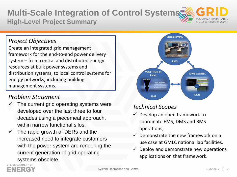
Project ObjectivesCreate an integrated grid management framework for the end-to-end power delivery system – from central and distributed energy resources at bulk power systems and distribution systems, to local control systems for energy networks, including building management systems.
Technical Scopes✓ Develop an open framework to
coordinate EMS, DMS and BMS
operations;
✓ Demonstrate the new framework on a
use case at GMLC national lab facilities.
✓ Deploy and demonstrate new operations
applications on that framework.
Multi-Scale Integration of Control Systems High-Level Project Summary
Problem Statement✓ The current grid operating systems were
developed over the last three to four
decades using a piecemeal approach,
within narrow functional silos.
✓ The rapid growth of DERs and the
increased need to integrate customers
with the power system are rendering the
current generation of grid operating
systems obsolete.
10/6/2017System Operations and Control 3
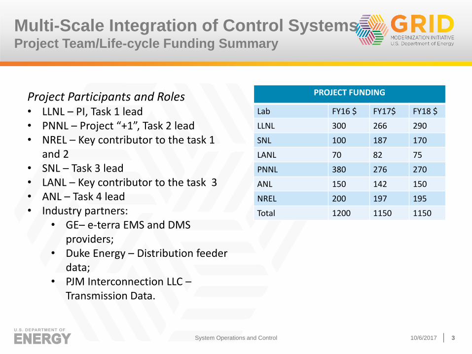
PROJECT FUNDING
Lab FY16 $ FY17$ FY18 $
LLNL 300 266 290
SNL 100 187 170
LANL 70 82 75
PNNL 380 276 270
ANL 150 142 150
NREL 200 197 195
Total 1200 1150 1150
Project Participants and Roles• LLNL – PI, Task 1 lead• PNNL – Project “+1”, Task 2 lead• NREL – Key contributor to the task 1
and 2• SNL – Task 3 lead• LANL – Key contributor to the task 3• ANL – Task 4 lead• Industry partners:
• GE– e-terra EMS and DMS providers;
• Duke Energy – Distribution feeder data;
• PJM Interconnection LLC –Transmission Data.
Multi-Scale Integration of Control Systems Project Team/Life-cycle Funding Summary

October 6, 2017 4
Decoupled transmission and distribution
operations are insufficient for complex smart
grid systems
LLNL-PRES-729081

Specific improvements/advancements
targeted by the project
Key innovations and project uniqueness
• An framework to coordinate EMS, DMS, and BMS operations, and being the FIRST in the industry to demonstrate the new framework on an industry test system.
• New transformative operations applications (probabilistic risk-based operations and forecasting data integration and decision support) that transform or extend existing EMS and DMS applications.
Technical tasks
• Task 1: Use case development
• Task 2: Open framework development for EMS/DMS/BMS integration
• Task 3: Integration of new DMS/BMS applications into EMS operations models
• Task 4: New application: EMS/DMS/BMS uncertainty modeling and forecasting method
10/6/2017System Operations and Control 5

10/6/2017System Operations and Control 6
This project will support DOE’s GMI to accomplish the following three Major Technical Achievements that will yield significant economic benefits of a modernized grid:
► Reduce the economic costs of power outages. It will help grid operators leverage distributed energy resources and avoid conditions that could lead to load shedding or cause outages.
► Decrease the cost of reserve margins while maintaining reliability. It will substantially reduce the amount of system reserve capacity needed to cope with generation and load fluctuations, while maintaining and even increasing system reliability.
► Decrease the net integration costs of distributed energy resources. EMS/DMS/BMS coordination with controllability to engage response loads will help balance the variability of DERs.
Expected benefits to electric utilities
4.0 System Ops and Control
4.2 Develop Coordinated System
Controls
4.2.1 Develop prototype EMS, DMS
and BMS
4.2.2 Incorporate probabilistic
approach
4.2.3 Develop open framework to
coordinate EMS, DMS and BMS
3.0 Sensing and Measurements
3.3 Enhance Sensing for the Transmission
System
3.3.2Analyze the economic and
reliability benefits of improved renewable
forecasting

10/6/2017 7System Operations and Control
Multi-Scale Integration of Control Systems Key Project Milestones and Status
Milestone (FY16-FY18) Status Due Date
FY16 Mid-year Milestones: Completed the use case report and data exchange requirements/protocols report.
Done 12/1/2016
FY16 Annual Milestones: Complete integration of LANL ED with SNL UC engine; Complete integration of renewable forecasting into UC and ED.
Done 3/30/2017
FY17 Annual Milestones: Demonstrate integration of DMS and BMS information on the use case proposed under task 1; Complete the implementation and testing of UC and ED into EIOC.
40% 3/30/2018
FY18 Annual Milestones: Successfully demonstrate integrated EMS/DMS/BMS platform; Demonstrate new DMS/BMS applications in UC/ED EMS; Demonstrate the uncertainty modeling and forecasting method in the integrated EMS/DMS/BMS system.
Not started 3/30/2019

10/6/2017 8System Operations and Control
Multi-Scale Integration of Control Systems Overall Project Budget (Planned vs Spending)
FY17 Planned FY17 Spending Variance
$1150K $1093K +$57K (<5%)

10/6/2017System Operations and Control 9
• Completed Version 1 of use case document and communication/control requirements document (Go/No-Go Milestone).
• the connection between EIOC at PNNL and IDMS at NREL through the ICCP link (engaged the vendor, coordinating with another two GMLC projects. )
• the connection between VOLTTRON™ at PNNL and IDMS at NREL through VOLTTRON™ Internet Protocol (Standardization is important)
• Collected Duke distribution data and Identified PJM transmission data for the demo.
Multi-Scale Integration of Control Systems FY16 Mid-year Milestones Accomplishments Summary
Interface Definition

We have completed the use case report
October 6, 2017 10GMLC Lab Call Project Summaries
Use Case Description
► Multi-scale integration of controls systems (EMS/DMS/BMS integrations) help coordinate and operate new distributed control schemes which utilize PV inverters and demand response programs to mitigate voltage instability issues.
► EMS - Out of the 10 PJM IROLs, 8 of them are reactive power interfaces. We will use VSA (Voltage Stability Assessment) tool to assess system status and provide control suggestions.
► DMS - When voltage instability occurs, each PV inverter supplies the maximum available reactive power output and supports transmission Varemergency demand.
► BMS - Demand response programs can also be called to reduce air-conditioner compressor induction motor load. This helps recover system voltage to acceptable level instantly and prevent system voltage collapse.
LLNL-PRES-729081

10/6/2017System Operations and Control 11
We will use VSA (Voltage Stability Assessment) tool to assess system status and provide control suggestions in two categories:
► Reactive power control
◼ Switch on/off capacitors and reactors. Adjust LTC and PAR tap positions.
◼ Adjust generator var output.
◼ Distributed var support from smart inverters.
► Real power control
◼ Redispatch generator MW output.
◼ Provide load shedding suggestion based on buses and TOs
◼ Demand response from DMS/BMS
Use Case: Leveraging scaled-up smart
inverters and DR to mitigate transmission
voltage stability problems
Example: Increase Load Margin Interface through extra
Var support
Limiting Contingency: Contingency 1234 Pre-Control Load Pre-control load margin: 1863 MW
VSA Control Solution:• T option: change gen terminal voltage
• D option: send X Mvar reactive request command to
DMSPost-control load Margin: 1883 MW
Source: PJM

We have completed communication/control requirements document
October 6, 2017 12GMLC Lab Call Project Summaries
► the connection between EIOC at PNNL and IDMS at NREL through the ICCP link (engaged the vendor, coordinating with another two GMLC projects. )
► the connection between VOLTTRON™ at PNNL and IDMS at NREL through VOLTTRON™ Internet Protocol (Standardization is important)
Interface Definition

10/6/2017System Operations and Control 13
• Completed the benchmarking of stochastic unit commitment and economic dispatch;
• Completed the report of a summary on major uncertainty sources for grid operations;
• Completed integration of LANL ED with SNL UC engine; Complete integration of renewable forecasting into UC and ED;
• Completed interface definition of integrating stochastic wind forecasting, stochastic UC and ED into EIOC.
Multi-Scale Integration of Control Systems FY16 Annual Milestones Accomplishments Summary
Integration of Advanced Applications in to EIOC

We used WECC-240 Bus Case for
testing UC and ED integration
October 6, 2017 14
1. Munoz, F. and Watson, J.P, Comp. Management Science 12(4), March 2015
► Full PJM case is
problematic for
testing EMS-
UC/ED
▪ Solve time
▪ Data issues
▪ Leveraging
reference UC case
being developed in
ARPA-E Grid Data
project
▪ First of its kind

WECC-240 (with ARPA-E Grid Data)
October 6, 2017 15
Basic copperplate
ED data(loads, gen cost
curves etc.)
Network Data
UC specific data
(ramp rates, startup/shutdown
cost etc.)
Wind data(BPA – actual
hourly realizations + hourly forecasts upto 24 hours for
14 months)
Available data
ED test caseDATA READY
UC test caseDATA READY
Stochastic UC/ED test caseData in progress

We have completed integration of
renewable forecasting into UC and ED
October 6, 2017 16
E.g., MATLAB parser for Matpower cases
ED
EMS
Unit on/off status per hour
Power system
data
Wind forecast
scenarios EMS-UC (python): Reads data and creates stochastic UC model using pyomo
pyomo (python): algebraic modeling language for describing MILP
CPLEX/Gurobi: Solves optimization
CSV, json

10/6/2017System Operations and Control 1717
NWP Output Data Weather Data Off-site
Met Data
Site Power Gen
& Met Data
Forecast Results
Physical Models Statistical Models
Wind Forecasts are the Result of
Combination of a Diverse set of Models
and Input Data
Uncertainty / Wind Power Forecasting

Progress to Date
► BMS ADR Supervisory Controller developed and tested to support the
initial use case
► Script developed allowing us to adapt any EnergyPlus model for
integration with the BMS ADR Supervisory Controller
► BMS ADR Supervisory Controller tested with a prototypical DOE
EnergyPlus models as well as a model of PNNL’s SEB
► Connection verified over VIP between the DMS and BMS
We are working on the integration of DMS and BMS
information for the proposed use case.
10/6/2017System Operations and Control 18
Multi-Scale Integration of Control Systems FY17 Annual Milestones Accomplishments Summary

10/6/2017System Operations and Control 19
DMS-BMS Implementation
EnergyPlusAgent
LoadAgent
EnergyPlusBuilding Model
DistributionManagement
System
Demand Response
Agent
Load Equipment Specifications / Reduced Order
Thermal Models
Internet
VOLTTRON
Message Bus
Message Bus
Weather Agent
Load Flexibility/ Cost Curves
Comm.Agent
Control Agent
Building ADR Supervisory Control System
Aggregation Node
NREL PNNL
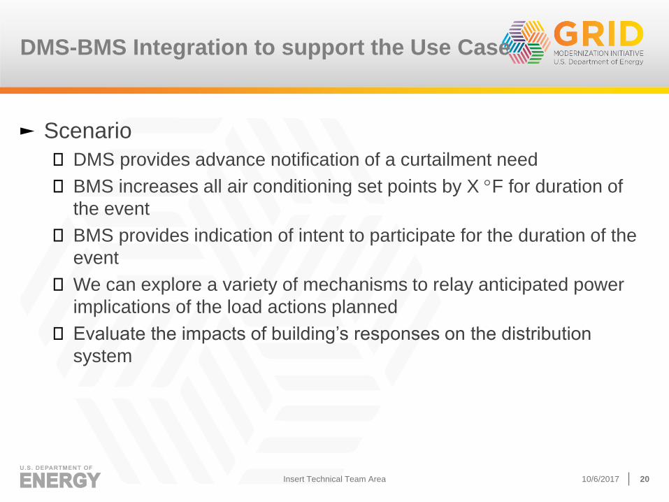
► Scenario
◼ DMS provides advance notification of a curtailment need
◼ BMS increases all air conditioning set points by X F for duration of
the event
◼ BMS provides indication of intent to participate for the duration of the
event
◼ We can explore a variety of mechanisms to relay anticipated power
implications of the load actions planned
◼ Evaluate the impacts of building’s responses on the distribution
system
DMS-BMS Integration to support the Use Case
10/6/2017Insert Technical Team Area 20

messageType Type of message being transmitted (e.g. “event notification,” “diagnostics,” “event response,” “bid,” “bid
response,” etc.)
responseRequired Required message response (e.g. “no response required,” “provide status,” “event participation,” etc.)
eventID A unique identifier for the event within the context of the DMS
modificationNumber A value that is incremented with each modification of the event message by the DMS
rID Resource unique identifier
responseIndicator Logical indicating that the message is a response to event message
eventType Indicates event context or type and may dictate which programmatic group of participants will be affected
priorityLevel Numerical value giving the event priority (i.e. from advisory to critical)
createdDateTime Date time when message was created
eventDateTime Date time of anticipated or active event
responseTime Speed of response required
eventDuration Duration of event
eventStatus Status of the event (e.g. “near,” “far,” “active,” “canceled,” “completed”)
responseAction Requested load action (e.g. “curtail load,” “increase load”)
incentiveStructure Message indicating the type of price-based incentive or penalty during event (e.g. “price multiple,” “absolute
price,” “cost curve,” etc.)
Incentive Value of incentive or penalty
currentPower Current power demand of the resource
Participation Logical indication of participation
parDuration Duration of participation
powerResponseType Type of power response provided
powerResponse Estimate power implications of response action.
DMS-BMS Interface Message Content
10/6/2017Insert Technical Team Area 21

10/6/2017System Operations and Control 22
► Duke’s Test Feeder
◼ In Duke’s North Carolina service territory
◼ Nominal voltage is 12.47 kV
◼ Native winter peak load of 5.26 MW
◼ One 5-MW PV plant
► Existing Utility Equipment
◼ Substation load tap changer
◼ Two capacitor banks
◼ Three sets of voltage regulators
► Data – 1 year of 1-minute resolution data
◼ Feeder head substation
◼ Reclosers
Distribution Test System/DMS Functionality
► Bus Load Allocation◼ Allocate the active and reactive power
consumption of all loads
◼ Closely match the available measurement values
► Distribution Power Flow◼ Voltage magnitude and angle at all
nodes
◼ Power flows through all feeder segments
► Integrated Volt/VAR Control (IVVC)◼ Determine an optimal set of control
actions for voltage regulating devices
◼ Achieve one or more specific operating objectives
◼ Avoid violating any of the fundamental operating constraints
◼ Devices include LTCs, voltage regulators, capacitors, and PV inverters

10/6/2017System Operations and Control 23
• This project coordinates with another foundational projects -1.4.10 (control theory) and 1.4.15 (integrated TDC).
• This project coordinates with core areas 1.2.1 (grid architecture) and 1.2.2 (interoperability) to use appropriate future system architecture and interoperability standards to ensure project success.
• This project is a part of the DOE ADMS program and coordinates closely with other efforts under the program; this project coordinates with Cat 2 WindViewproject to visualize wind forecasting.
• This project leverages previous ARPA-E and OE’s AGM research results on stochastic optimization area.
• Participated and presented at the Advanced Distribution Management System (ADMS) Industry Steering Committee kick-off workshop, April 2016
• Participated and presented at the 2016 IEEE Innovative Smart Grid Technologies ADMS panel, September 2016
• Will present at the 2017 IEEE Innovative Smart Grid Technologies ADMS panel, April 2017.
Multi-Scale Integration of Control Systems Project Integration and Collaboration
1.4.11 EMS/DMS/
BMS Integration
1.4.10 Control Theory
1.2.2 Inter-operability
GM0063 Open
source platform for ADMS
GM0237 ADMS
testbed
GM00187 Community control of
DER
ANL/NREL's WindView
Previous ARPA-E and OE's AGM research
1.2.1 Grid Architectur
e
1.4.15 Integrated
TDC simulation

10/6/2017System Operations and Control 24
FY18 Plan
Key activities/milestones planned for FY18 include:
► Complete the implementation and testing of UC and ED into EIOC computational environment using WECC 240 bus model by the end Q1 of FY18.
► Demonstrate the integration of DMS and BMS using Duke Energy’s data by the end Q2 of FY18.
Description Severity Response
The main risk associated with the
integration of different control systems at
different national labs (the EIOC and
VOLTTRON at PNNL and IDMS at NREL) is
network latency, which can impact
communication between control systems.
Medium PNNL and NREL have collaborated
successfully in the past to
remotely connect the Gridlab-D
simulation at PNNL with the ESIF
at NREL. The network latency
issue has been discussed and
considered.
Risks/Mitigation plans

10/6/2017System Operations and Control 25
FY18 Plan
Description Criteria Date
If the ESIF SCADA data and utility data from the
virtual distribution feeder cannot be obtained
by the end of the second quarter of FY18, will
use existing data that PNNL and NREL previously
acquired from another test site, such as AMI
data from PNNL and the AEP gridSMART
demonstration.
If utility testing data are
obtained.
03/31/2018
Go/no-go decision• We have received both PJM-EMS and Duke-DMS data for this project

10/6/2017System Operations and Control 26
Industry Collaborators and Roles• GE– e-terra EMS and DMS
providers;• Duke Energy – Distribution feeder
data;• PJM Interconnection LLC –
Transmission Data.
Tech Transfer Activities
Conference presentations/Reports • DMS - BMS Interface Definition,
PNNL Technical Report, Nov, 2016;
• Multi-scale Integration of Control Systems Use Case, LLNL Technical Report, LLNL-TR-712277, Nov, 2016;
• DOE GMLC Peer Review Presentation, April 2017;
• IEEE 2017 ISGT ADMS Panel Presentation Release number-LLNL-PRES-729081, April 2017;
• Proposed to participate in IEEE 2018 GM TSO-DSO panel;
10/6/2017System Operations and Control 27
Liang Min, PhD
Associate Program Leader
Cyber and Infrastructure Resilience
Phone: 925-422-1187
Email: [email protected]
Lawrence Livermore National Laboratory
Contact Information
Mark Rice, PhD
Staff Scientist
Electricity Infrastructure
Phone: 509-375-2435
Email: [email protected]
Pacific Northwest National Laboratory