multi-site plant assessment statement introduction …
TRANSCRIPT
© Capability Resources Page 1 of 25
MULTI-SITE PLANT ASSESSMENT STATEMENT INTRODUCTION TO SITE MDG 15 & AS4242
For
CLIENT:
This Plant Assessment Statement has been derived from the requirements of MDG15, MDG41, AS 4242 and AS3000, where applicable
Disclaimer Capable Training Pty Limited trading as Capability Resources has prepared this document: subject to the terms and conditions of engagement between Capability Resources and the party who has engaged Capability Resources to prepare this document, which unless expressly agreed in writing to the contrary, include Capability Resources’ general terms and conditions of contract; based on instructions and information provided by or on behalf of the Client; taking into account information known to Capability Resources at the date of this document or any earlier specified date; and solely for the specific purpose set out in the agreed scope of work forming part of the Contract or otherwise confirmed in writing by Capability Resources. To the maximum extent permitted by law, neither Capability Resources nor any of its employees, agents or contractors accepts any liability or responsibility of any kind arising out of or in connection with: a) the use of, or reliance on, this document (or any part of it) by any person other than the Client; b) the use of, or reliance on, this document (or any part of it) by the Client for any purpose other than the Agreed Purpose; c) reliance on inaccurate or misleading information provided by or on behalf of the Client or obtained from any third party source, except to the extent it was not reasonable in all the circumstances for Capability Resources to rely on that information; or d) any fact or circumstance arising after the Effective Date. The provisions set out above do not limit or otherwise prejudice any exclusions or limitations of liability in the Contract.
Plant Description:
Plant ID Number:
Plant Serial Number:
Initial Inspection Date:
Verification Inspection Date:
Inspected by: Capability Resources
CONTENTS
Section 1 Inspection Section 2 Verification Section 3 Owner Declaration Section 4 Site Acceptance
C apability Resources 20 Shipley Drive, Rutherford NSW 2320 P hone: +61 2 4932 7148 ABN: 95 108 621 101 Email: [email protected] Website: www. capres.com.au
17861
Dozer
CAT00D8TCMLN00326
07/02/2018
15/02/2018
128
Ditchfield Contracting

Version: 4.1 Issued: 02/07/2016 © Capability Resources Page 2 of 25
MULTI-SITE MDG15 PLANT ASSESSMENT STATEMENT
Capability Resources 20 Shipley Drive, Rutherford NSW 2320 Phone: +61 2 4932 7148 ABN: 95 108 621 101 Email: [email protected] Website: www. capres.com.au
SECTION 1 - Inspection
1. Plant Details (identify specific plant details)
Client: Client Contact Person / Representative: Client contact Phone Client contact Email: Plant Owner: Job Number: Client Purchase Order: Inspection Date: Re-inspection Date: Plant Description: Plant Manufacturer: Plant Model: Date of Manufacture: Plant Serial number: Registration No if Applicable
Plant Unit number: Plant Hours / km’s: Plant Maintained by who: Unladed Mass (Mobile Plant only): Maximum Payload (Mobile Plant only): Maximum Persons Transported (Mobile Plant only): Inspected by:
Other comments:
17861
Ditchfield Contracting
Andy Deane
0447 656 992
Ditchfield Contracting
07/02/2018
15/02/2018
Dozer
Caterpillar
D8T
CAT00D8TCMLN00326
128
128
8,750 Hours
Ditchfield Contracting
39,420kg
N/A
1
Alan Crumbley

Version: 4.1 Issued: 02/07/2016 © Capability Resources Page 3 of 25
MULTI-SITE MDG15 PLANT ASSESSMENT STATEMENT
Capability Resources 20 Shipley Drive, Rutherford NSW 2320 Phone: +61 2 4932 7148 ABN: 95 108 621 101 Email: [email protected] Website: www. capres.com.au
C22 Equipment Photograph/s (4 angles)
C23 Photo of plant serial number

Version: 4.1 Issued: 02/07/2016 © Capability Resources Page 4 of 25
MULTI-SITE MDG15 PLANT ASSESSMENT STATEMENT
Capability Resources 20 Shipley Drive, Rutherford NSW 2320 Phone: +61 2 4932 7148 ABN: 95 108 621 101 Email: [email protected] Website: www. capres.com.au
2. COMPLIANCE CHECKLIST
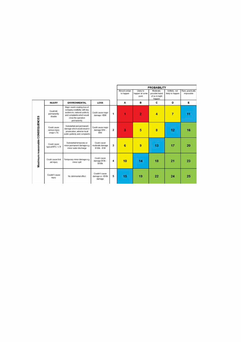
Compliance status to be nominated as: C = Compliance NC = Non Compliance NA = Not Applicable
MEDIUM/HIGH risk non-compliance items will need controls implemented to reduce the risk to LOW. A further inspection will need to be completed to verify the adequacy of the controls.
Section 2 will need to be completed prior to the issuance of final report.
Section A: General Site Requirements CA1 Flag fitted if under 4m CA2 Flashing beacon Colour CA3 Quick fill fittings – Large earthmoving Equipment CA4 2-way radio provision CA5 Plant Reflective Identification min 220mm letters CA6 Baffles for water and fuel trucks CA7 Housekeeping CA8 Plant in operable condition
Section B: Plant Safety File General Documentation
CB1 Operations and Maintenance manual CB2 Drawings and Schematics CB3 Change Management - Commissioning
Risk Assessments: CB4 Design Risk Assessment CB5 Operational Risk Assessment CB6 Maintenance Risk Assessment CB7 Fire Risk Assessment
Maintenance and Systems: CB10 Towing Instructions (if applicable) CB11 Maintenance Records CB12 New Plant - Commissioning CB13 Pre-Start Inspection CB14 Brake inspection and test reports CB15 RMS Inspection CB16 Sound Analysis CB17 Vibration Analysis CB18 NDT Reports CB19 Pressure Vessels CB20 Safety Data Sheets CB21 CB22 Chain / Sling / Lifting Gear Register
✔ ●
Amber●
✔
✔
✔
✔
✔
✔
✔
●
✔
✔
✔
✔
✔
✔
✔
✔
●
●
✔
✔
✔
●
●
●
●

Version: 4.1 Issued: 02/07/2016 © Capability Resources Page 5 of 25
MULTI-SITE MDG15 PLANT ASSESSMENT STATEMENT
Capability Resources 20 Shipley Drive, Rutherford NSW 2320 Phone: +61 2 4932 7148 ABN: 95 108 621 101 Email: [email protected] Website: www. capres.com.au
CB23 Machine Specific Isolation Procedures CB24 Low Voltage Equipment - Electrical Test Tags fitted CB25 Confined Space CB26 Stability Report - Water and Fuel Trucks CB27 Crane Safe Report
Section C: Item Registration
CC1 Item Registration Document Number CC2 Plant Registration Number marked on equipment CC3 Within Expiry Date CC4 Pressure vessels A, B or CCC5 Concrete placement units with delivery boomsCC6 Mobile cranes > 10 tonnesCC7 Man Boxes
Section D: Design Registration
CD1 Design Registration Form / Number CD2 New registration CD3 Pressure Vessels A, B, C, DCD4 Hoists - platform movement > 2.4 metres, to lift peopleCD5 Concrete placement units with delivery boomsCD6 Boom-type elevating work platformsCD7 Mobile cranes > 10 tonnes
●
●
●
●
●
●
●
●
✔
✔
●
●
●
●
●
●
●
●
●
●
●
Version: 4.1 Issued: 02/07/2016 © Capability Resources Page 6 of 25
MULTI-SITE MDG15 PLANT ASSESSMENT STATEMENT
Capability Resources 20 Shipley Drive, Rutherford NSW 2320 Phone: +61 2 4932 7148 ABN: 95 108 621 101 Email: [email protected] Website: www. capres.com.au
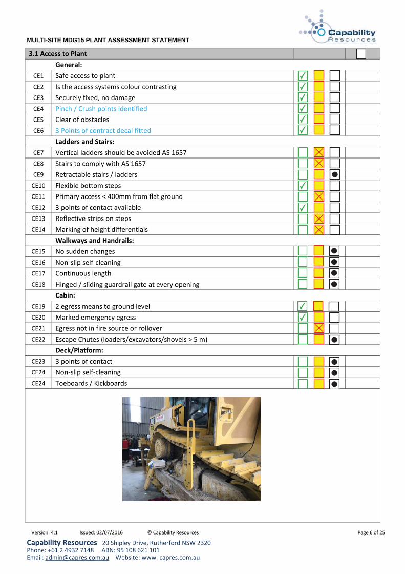
3.1 Access to Plant General:
CE1 Safe access to plant CE2 Is the access systems colour contrasting CE3 Securely fixed, no damage CE4 Pinch / Crush points identified CE5 Clear of obstacles CE6 3 Points of contract decal fitted
Ladders and Stairs: CE7 Vertical ladders should be avoided AS 1657 CE8 Stairs to comply with AS 1657 CE9 Retractable stairs / ladders
CE10 Flexible bottom stepsCE11 Primary access < 400mm from flat ground CE12 3 points of contact available CE13 Reflective strips on steps CE14 Marking of height differentials
Walkways and Handrails: CE15 No sudden changes CE16 Non-slip self-cleaning CE17 Continuous length CE18 Hinged / sliding guardrail gate at every opening
Cabin: CE19 2 egress means to ground level CE20 Marked emergency egress CE21 Egress not in fire source or rollover CE22 Escape Chutes (loaders/excavators/shovels > 5 m)
Deck/Platform: CE23 3 points of contact CE24 Non-slip self-cleaning CE24 Toeboards / Kickboards
✔
✔
✔
✔
✔
✔
✔
✔
●
●
●
●
●
✔
●
●
●
●
✔

Version: 4.1 Issued: 02/07/2016 © Capability Resources Page 7 of 25
MULTI-SITE MDG15 PLANT ASSESSMENT STATEMENT
Capability Resources 20 Shipley Drive, Rutherford NSW 2320 Phone: +61 2 4932 7148 ABN: 95 108 621 101 Email: [email protected] Website: www. capres.com.au
3.2 Brakes Safety Critical Systems: Non Compliance should be relayed immediately to your supervisor.
CF1 Brakes fail to safe – OR - CF2 Dual brake system fitted CF3 Interlock to prevent drive through brake
3.3 Brake Performance
CG1 Park Brake able to be applied from operator’s cab CG2 Park brake holding CG3 Brake Pressure warning CG4 Brake Drag warning CG5 Not rely on exhaustible energy
3.4 Control Functions Safety Critical Systems: Non Compliance should be relayed immediately to your supervisor.
CH1 Audible Warning Device (e.g. manually initiated horn) CH2 Supplemented horn if applicable CH3 Pre-Start Warning CH4 Reversing audible alarm CH5 Audible travel alarm
✔
✔
✔
✔
✔
✔
✔
✔
✔
✔
✔
●
●

Version: 4.1 Issued: 02/07/2016 © Capability Resources Page 8 of 25
MULTI-SITE MDG15 PLANT ASSESSMENT STATEMENT
Capability Resources 20 Shipley Drive, Rutherford NSW 2320 Phone: +61 2 4932 7148 ABN: 95 108 621 101 Email: [email protected] Website: www. capres.com.au
3.5 Engine Compartment Risk Fuel System
CI1 Services protected from hot spots and wear CI2 Non leaking fuel caps CI3 High Pressure lines to be metal or metal sheathed eg injector lines CI4 Fuel Hoses to be well supported with no signs of wear or leaking CI5 Fuel filters to be of metal construction
CI6 Fuel filters to have metal shield fitted over polycarbonate filter CI7 Low Pressure fuel hoses outer layer metal braided
CI8 Low Pressure fuel hoses inner layer metal braided C19 Low Pressure fuel hoses are OEM rubber fuel hose C20 Low Pressure fuel hoses are OEM moulded plastic fuel hose C21 Fuel Hoses to be segregated from all other servicesC22 Fuel hoses are secured without hose clamps
C23 Fuel hoses are secured with hose clamps
Fuel filters to be of metal construction
Fuel hoses are secured with hose clamps
✔
✔
✔
✔
✔
✔
✔
●
Version: 4.1 Issued: 02/07/2016 © Capability Resources Page 9 of 25
MULTI-SITE MDG15 PLANT ASSESSMENT STATEMENT
Capability Resources 20 Shipley Drive, Rutherford NSW 2320 Phone: +61 2 4932 7148 ABN: 95 108 621 101 Email: [email protected] Website: www. capres.com.au
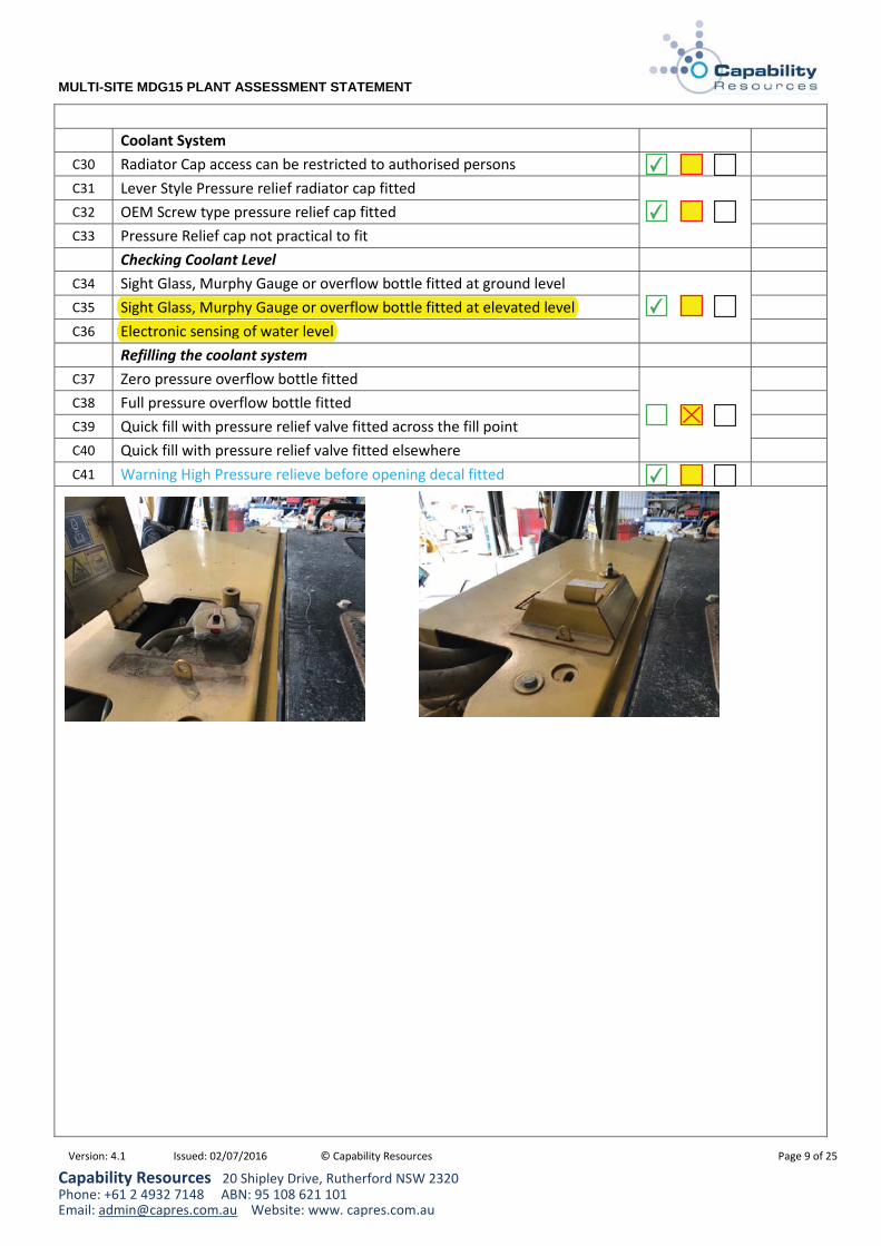
Coolant System C30 Radiator Cap access can be restricted to authorised persons C31 Lever Style Pressure relief radiator cap fitted C32 OEM Screw type pressure relief cap fitted C33 Pressure Relief cap not practical to fit
Checking Coolant Level C34 Sight Glass, Murphy Gauge or overflow bottle fitted at ground level C35 Sight Glass, Murphy Gauge or overflow bottle fitted at elevated level C36 Electronic sensing of water level
Refilling the coolant system C37 Zero pressure overflow bottle fitted C38 Full pressure overflow bottle fittedC39 Quick fill with pressure relief valve fitted across the fill point C40 Quick fill with pressure relief valve fitted elsewhere C41 Warning High Pressure relieve before opening decal fitted
Electronic sensing of water levelSight Glass, Murphy Gauge or overflow bottle fitted at elevated level
✔
✔
✔
✔

Version: 4.1 Issued: 02/07/2016 © Capability Resources Page 10 of 25
MULTI-SITE MDG15 PLANT ASSESSMENT STATEMENT
Capability Resources 20 Shipley Drive, Rutherford NSW 2320 Phone: +61 2 4932 7148 ABN: 95 108 621 101 Email: [email protected] Website: www. capres.com.au
Exhaust System
C50 Medium Truck engine bays not checked – Signage DANGER Isolate Machine Before Tilting Cab (positioned on each side of cab)
C51 Is the Turbo guarded to prevent inadvertent contact C52 Is a turbo wrap fitted to prevent an ignition point C53 Is the turbo inaccessible and on the opposite side to the fuel system C54 Is the turbo oil feed line a steel tube C55 Is the turbo oil feel hose steel braided OR C56 If steel braided, is a heat proof sheath fitted to divert any oil leaks away C57 Is the rest of the exhaust guarded to prevent inadvertent contact C58 Are the guards fitted so there is no entrapment of oils C59 Is full exhaust wrap fittedC60 Is the tailpipe protected from inadvertent contact if applicable C61 Is there a hydraulic fan fitted with the potential to fan oil onto the exhaust C62 Is a firewall fitted between the engine and the hydraulic system C63 Is there any un guarded hydraulic hoses adjacent to the exhaust C64 No obvious exhaust leaks C65 Guards made of fire resistant material C66 The exhaust relies upon the engine cover for guarding C67 Hot Parts warning decals near any accessible area’s
Is the Turbo guarded to prevent inadvertent contactIs a turbo wrap fitted to prevent an ignition point
Is the turbo oil feed line a steel tube
Is full exhaust wrap fitted
●
✔
✔
✔
✔
✔
●
✔
✔
✔
✔

Version: 4.1 Issued: 02/07/2016 © Capability Resources Page 11 of 25
MULTI-SITE MDG15 PLANT ASSESSMENT STATEMENT
Capability Resources 20 Shipley Drive, Rutherford NSW 2320 Phone: +61 2 4932 7148 ABN: 95 108 621 101 Email: [email protected] Website: www. capres.com.au
Radiator Cooling Fan Guarding
C70 Medium Truck engine bays not checked – Signage DANGER Isolate Machine Before Tilting Cab (positioned on each side of cab)
C71 Is the radiator fan guarded to AS 4024 – fully guarded C72 Is the radiator fan guarded for inadvertent contact C73 The fan is accessible and relies upon the engine cover for guarding
Rotating Fan Belts C74 Are the fan belts guarded to AS 4024 – fully guarded C75 Are the fan belts guarded for inadvertent contact C76 Are the fan belts relying upon the engine cover for guarding C77 Are all guards securely mounted C78 Guards cannot be removed during normal operation ie bolted C79 Are the any other rotating parts that are accessible in the engine bay C80 Rotating Parts Warning decals near any accessible rotating parts
Are the fan belts guarded for inadvertent contactAre the fan belts relying upon the engine cover for guarding
Is the radiator fan guarded for inadvertent contactThe fan is accessible and relies upon the engine cover for guarding
✔
✔
✔
✔
✔
✔
●

Version: 4.1 Issued: 02/07/2016 © Capability Resources Page 12 of 25
MULTI-SITE MDG15 PLANT ASSESSMENT STATEMENT
Capability Resources 20 Shipley Drive, Rutherford NSW 2320 Phone: +61 2 4932 7148 ABN: 95 108 621 101 Email: [email protected] Website: www. capres.com.au
3.6 Ergonomics CJ1 Operator controls in zones of comfort CJ2 Excess vibration controlled CJ3 Is the operators seat suspended and in good condition
CJ14 Seat Belt 3 point Lap Sash fitted CJ15 75mm inertial reel retractable lap belt CJ16 50mm inertial reel retractable lap belt CJ17 Non Inertia reel lap belt fitted CJ18 Seats, belts and anchor points undamaged and secure CJ19 Seat Belts to be worn for safe operation decal fitted in cabin
3.7 Fire Control Systems Safety Critical Systems: Non Compliance should be relayed immediately to your supervisor.
CK1 Fire risk assessment (one per plant specification)
CK2
Fire extinguisher quantity and location as determined from Fire Risk Assessment. A minimum of 2 x 9KG extinguishers shall be installed on larger machinery, 1x outside the operators cab and 1x accessible from ground level. Service Interval – 3 monthly on all fire extinguishers. All fire extinguishers should be rated 80B(E) 9kg
Ancillary equipment 1 Extinguisher min 80B(E) 4.5kg
CK3A fire suppression system should be provided on all equipment (for heavy equipment only). Service Interval High Risk Plant (e.g. drills) - 3 monthly, Service Interval Other Plant – 6 monthly.
CK4 Fire suppression system bottles are within service date. Interval – 5 yearly.
CK5 Manual activation of the fire system shall be available from both the operator’s cab and ground level.
CK6 A failsafe shut off valve shall be fitted to the fuel supply line (on equipment fitted with Fire Suppression).
75mm inertial reel retractable lap belt
✔
✔
✔
✔
✔
✔
✔
✔
●
●
●
●

Version: 4.1 Issued: 02/07/2016 © Capability Resources Page 13 of 25
MULTI-SITE MDG15 PLANT ASSESSMENT STATEMENT
Capability Resources 20 Shipley Drive, Rutherford NSW 2320 Phone: +61 2 4932 7148 ABN: 95 108 621 101 Email: [email protected] Website: www. capres.com.au
3.8 Fluid Systems
CL1 Hoses not damaged (eg no exposed steel braiding) CL2 Hoses have secondary protection where required CL3 Adequate bending radius CL4 Separate routing and adequate clamping CL5 Hydraulic lift cylinders - load lock – Anti burst crane valves fitted CL6 Burst Protection fitted to all high risk areas - ISO 3457 and EN474-1 state,
"Hydraulic hoses containing fluid with a pressure of more than 5MPa (50 bar – 725psi) and/or having a temperature over 50°C, and which are locatedwithin 1.0 m of the operator, shall be guarded."
CL7 Burst Protection adequately secured CL8 Burst Restraint fitted where applicable eg excavators
3.9 Guards & Shields
Guards – other than in the engine bay CM4 Securely mounted CM5 Cannot be removed during normal operation CM6 Included in Pre-start inspection CM7 No entrapment of oils CM8 Accessible moving componentsCM9 Guards made of fire resistant material
CM13
CM14 Operators compartment shield CM15 Egress shielded CM16 Rotating or Hot Parts warning decals fitted if applicable
✔
✔
✔
✔
✔
✔
✔
●
●
●
●
●
●
●
●
●
●
●
●

Version: 4.1 Issued: 02/07/2016 © Capability Resources Page 14 of 25
MULTI-SITE MDG15 PLANT ASSESSMENT STATEMENT
Capability Resources 20 Shipley Drive, Rutherford NSW 2320 Phone: +61 2 4932 7148 ABN: 95 108 621 101 Email: [email protected] Website: www. capres.com.au
3.10 Markings, Signs & Identification CN1 Easily interpreted CN2 Durable and permanent. Positioned for visibility
Internal Cabin Labelling Required: CN3 Limits of Application provided in the cabin CN4 Inclinometer fitted CN5 Field of vision drawing CN6 Park-up procedure CN7 Noise Level in cabin or Hearing protection warning decal as applicable CN8 Pre-start inspection book in cabin CN9 In Case of Fire warning decal
CN10 Mobile phones not to be usedCN11 Emergency egress points CN12 Identification of all controls including direction of movement CN13 Emergency stop ‘EMERGENCY STOP’ (No abbreviated versions). CN14 Seat Belts to be worn for safe operation decal fitted in cabin
Other External Labelling Required: CN21 Spring applied component under pressure CN22 Noise Level outside cabin or Hearing protection warning decal as applicable CN23 Green and red zones for analogue gauges CN24 No multiplication factors on pressure gauges CN25 Digital gauges - indication of out of range pressure CN26 Automatic / remote start CN27 Fire Protection System CN28 Pinch Points identified
CN29 Crushing Could Occur (Loader Artic, Scraper Pivot, Dump Truck front wheels).
CN30 Confined Space Entry By Permit Only or Enclosed Work Area CN31 Isolation points CN32 Jump Start including voltageCN33 Harness Points CN34 Other labelling requirements
✔
✔
✔
✔
✔
✔
✔
✔
✔
✔
✔
✔
✔
✔
✔
●
●
●
✔
✔
●
●
✔
✔
✔
✔
✔
✔

Version: 4.1 Issued: 02/07/2016 © Capability Resources Page 15 of 25
MULTI-SITE MDG15 PLANT ASSESSMENT STATEMENT
Capability Resources 20 Shipley Drive, Rutherford NSW 2320 Phone: +61 2 4932 7148 ABN: 95 108 621 101 Email: [email protected] Website: www. capres.com.au
3.11 Lighting & Alarms CO1 Access lights CO2 Emergency lighting CO3 Reversing Lights CO4 Brakes and Direction Indicators CO5 Reflectors / Tape / Lights C05 Elevated light bar if applicable
3.12 Noise CP1 Sound reducing components are in good condition
3.13 Operator’s Cab & Protection Safety Critical Systems: Non Compliance should be relayed immediately to your supervisor.
CQ1 Operator Protective Structures CQ2 ROPS - mobile equipment and structure not compromised CQ3 FOPS - operator seated and structure not compromised CQ4 TOPS - Excavators and structure not compromised (1t – 6t Excavators) CQ5 OPG - Excavators and structure not compromised
Cabins CQ7 Enclosed and sound suppressed CQ8 Maximum visibility CQ9 Safety glass or equivalent all windows
CQ10 Windscreen wipers / washers CQ11 Secure storage space CQ12 No protrudences / sharp edges CQ13 Heating, Demisting and Fresh Air Supply (positive pressure) CQ14 Air Conditioning - In good condition and operational CQ15 Aftermarket items do not affect operator visibility CQ16 Rear view mirrors fitted and undamaged
✔
✔
✔
✔
●
●
✔
✔
✔
✔
●
●
✔
✔
✔
✔
✔
✔
✔
✔
✔

Version: 4.1 Issued: 02/07/2016 © Capability Resources Page 16 of 25
MULTI-SITE MDG15 PLANT ASSESSMENT STATEMENT
Capability Resources 20 Shipley Drive, Rutherford NSW 2320 Phone: +61 2 4932 7148 ABN: 95 108 621 101 Email: [email protected] Website: www. capres.com.au
3.14 Pressure Vessels
CR1 Accumulators pressure relief system for maintenance purposes CR2 PVC Piping non-critical or fail safe air systems CR3 Release pressure before work decal fitted
3.15 Steering
CS1 Power Steering - safe operation on power failure
CS2 Emergency steering shall be fitted on scrapers, articulated trucks and dump trucks.
CS3 Steering device lock on articulated vehicles
3.16 Towing, Jacking & Supporting CT2 OEM compliant attachment points and fittings CT3 Load capacity specified CT4 No chains fitted for towing of inoperable plant CT5 Rated tow hitch CT6 Towing safety chains fit for purpose CT7 Tow, lift, jack, tie down, support points: label / painted different colour
3.17 - 18 Wheels & Rims CU1 Rims and wheels in good condition and all nuts fitted
Rims >24” Stamped, rim register within hours No obvious cuts, significant damage, wear or deflation Wheel chocks fitted for all rubber tyred machines
CU Tracks – good condition, all grouser / track chain bolts in place
CU
CU CU
✔
✔
✔
✔
✔
✔
✔
✔
●
●
✔
●
●
●
●
●
●
●

Version: 4.1 Issued: 02/07/2016 © Capability Resources Page 17 of 25
MULTI-SITE MDG15 PLANT ASSESSMENT STATEMENT
Capability Resources 20 Shipley Drive, Rutherford NSW 2320 Phone: +61 2 4932 7148 ABN: 95 108 621 101 Email: [email protected] Website: www. capres.com.au
3.19 Proximity Detection And Collision Avoidance CW1 Proximity detection system operational if installed CW2 Reverse Camera system operational if installed
3.20 Emergency Shutdown
CX1 Large red push type button, yellow background, manually operated, automatic lock-off manual reset type
CX2 Fail safe or verification of functionally safety approach taken ie NC contacts CX3 Resetting of emergency stop shall not restart or reenergise equipment. CX4 Will stop the engine when depressed CX5 Preferred – will not allow cranking when depressed CX6 Clearly marked “EMERGENCY STOP” CX7 Yellow background CX8 Location in the operators cab and normal boarding point.
CX9 Wheeled equipment cab Emergency Stops shall retain emergency steering pressure when activated
CX10 Wheeled equipment cab Emergency Stops shall retain brakes when activated
CX11 Medium Size Truck – Process Stops fitted to shut down rear module system from the control points.
●
✔
✔
✔
✔
✔
✔
✔
✔
●
●
✔
●

Version: 4.1 Issued: 02/07/2016 © Capability Resources Page 18 of 25
MULTI-SITE MDG15 PLANT ASSESSMENT STATEMENT
Capability Resources 20 Shipley Drive, Rutherford NSW 2320 Phone: +61 2 4932 7148 ABN: 95 108 621 101 Email: [email protected] Website: www. capres.com.au
4 REQUIREMENTS FOR SPECIFIC TYPES OF PLANT CY1 Dump Trucks CY2 Dump body warning device when body up CY3 Dump Body Interlocks restricts low gear with body up CY4 Rear window rock guards fitted.
Tray down indicator CY5 No vertical access steps for primary access. CY6 Dump Body Restraint when raised
CY10 Dozer CY11 Access ladder system fitted (D10 and D11 size only).
CY12 Bonnet Harness Lanyard including Compliance Plate (D10 and D11 size only), or large access platforms fitted (for access to tilt cylinder lights).
CY13 Recommended - Pogo Sticks fitted to push arms. CY14 Dozer CHPP
CY15 Engine shut off tilt switches positioned in the cab CY16 Oxygen Tanks or Self Rescuer fitted in cab.
CY17 Cab Glass CAT Ultra 40 to prevent ingress of coal (excluding rear when fitted with Self Rescuer).
CY18 Belly guards removed for coal stockpiles. Keep front guard with tow point fitted.
CY19 Counter weight / Ripper emergency stop to be fitted Conveyors
CY20 All rollers guarded from access where accessible CY21 Emergency Stop Lanyard fitted to both sides of all accessible conveyor
Boom Type EWP
CY22 Generator Isolated – 240 volt inlet isolated if fitted CY23 No override switch on deadman controls CY24 Tilt out alarm CY25 Power failure – means of lowering CY26 Skyguard fitted
Truck Boom Mounted EWP CY27 Weight sensitive guard bar fitted over basket controls CY28 Power failure – means of lowering CY29 240 volt inlet locked out
●
●
●
●
●
●
●
●
●
●
●
●
●
●
●
●
●
●
●
●
●
●
●
●
●
●
Version: 4.1 Issued: 02/07/2016 © Capability Resources Page 19 of 25
MULTI-SITE MDG15 PLANT ASSESSMENT STATEMENT
Capability Resources 20 Shipley Drive, Rutherford NSW 2320 Phone: +61 2 4932 7148 ABN: 95 108 621 101 Email: [email protected] Website: www. capres.com.au
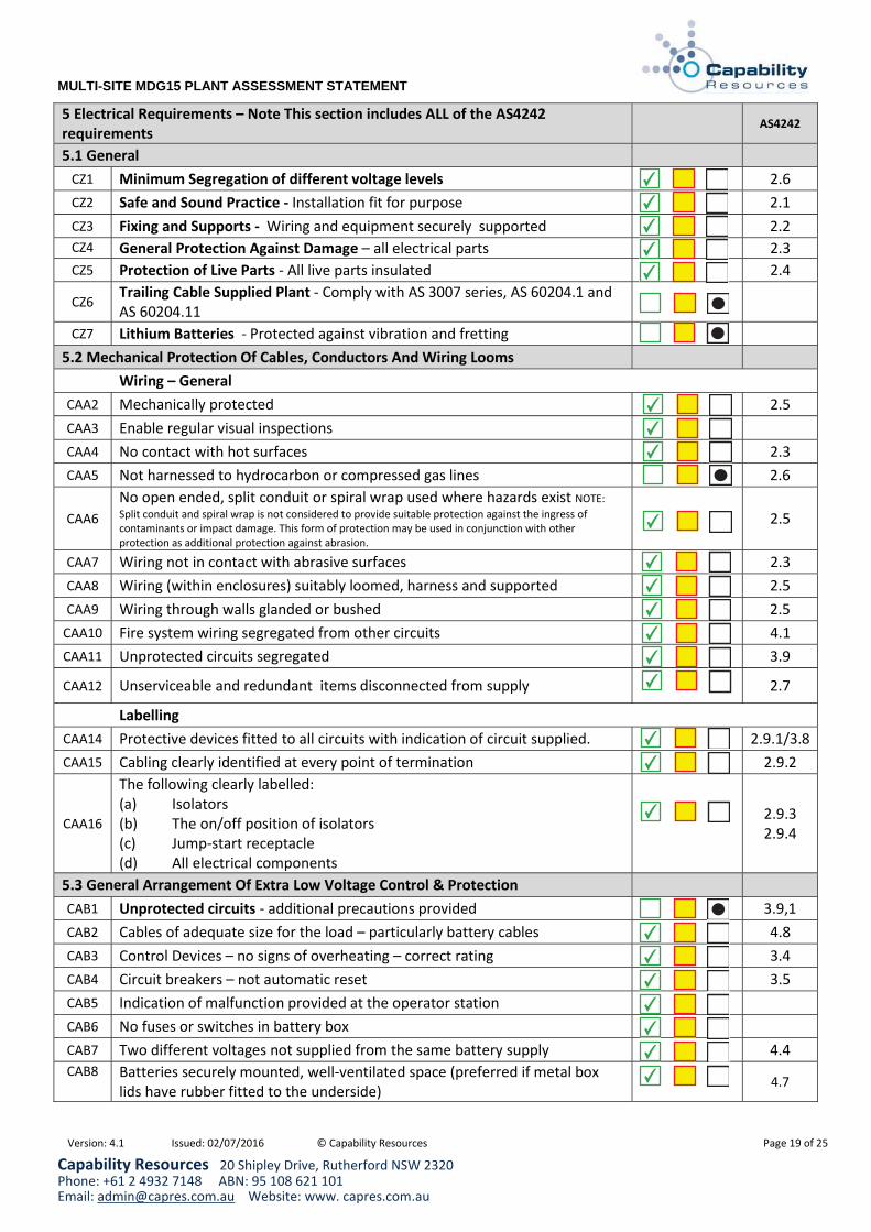
5 Electrical Requirements – Note This section includes ALL of the AS4242 requirements
AS4242
5.1 General CZ1 Minimum Segregation of different voltage levels 2.6 CZ2 Safe and Sound Practice - Installation fit for purpose 2.1 CZ3 Fixing and Supports - Wiring and equipment securely supported 2.2 CZ4 General Protection Against Damage – all electrical parts 2.3 CZ5 Protection of Live Parts - All live parts insulated 2.4
CZ6 Trailing Cable Supplied Plant - Comply with AS 3007 series, AS 60204.1 and AS 60204.11
CZ7 Lithium Batteries - Protected against vibration and fretting
5.2 Mechanical Protection Of Cables, Conductors And Wiring Looms Wiring – General
CAA2 Mechanically protected 2.5 CAA3 Enable regular visual inspections CAA4 No contact with hot surfaces 2.3 CAA5 Not harnessed to hydrocarbon or compressed gas lines 2.6
CAA6 No open ended, split conduit or spiral wrap used where hazards exist NOTE:Split conduit and spiral wrap is not considered to provide suitable protection against the ingress of contaminants or impact damage. This form of protection may be used in conjunction with other protection as additional protection against abrasion.
2.5
CAA7 Wiring not in contact with abrasive surfaces 2.3 CAA8 Wiring (within enclosures) suitably loomed, harness and supported 2.5 CAA9 Wiring through walls glanded or bushed 2.5
CAA10 Fire system wiring segregated from other circuits 4.1 CAA11 Unprotected circuits segregated 3.9
CAA12 Unserviceable and redundant items disconnected from supply 2.7
Labelling CAA14 Protective devices fitted to all circuits with indication of circuit supplied. 2.9.1/3.8 CAA15 Cabling clearly identified at every point of termination 2.9.2
CAA16
The following clearly labelled: (a) Isolators (b) The on/off position of isolators (c) Jump-start receptacle (d) All electrical components
2.9.3 2.9.4
5.3 General Arrangement Of Extra Low Voltage Control & Protection CAB1 Unprotected circuits - additional precautions provided 3.9,1 CAB2 Cables of adequate size for the load – particularly battery cables 4.8 CAB3 Control Devices – no signs of overheating – correct rating 3.4 CAB4 Circuit breakers – not automatic reset 3.5 CAB5 Indication of malfunction provided at the operator station CAB6 No fuses or switches in battery box CAB7 Two different voltages not supplied from the same battery supply 4.4 CAB8 Batteries securely mounted, well-ventilated space (preferred if metal box
lids have rubber fitted to the underside) 4.7
✔
✔
✔
✔
✔
●
●
✔
✔
✔
✔
●
✔
✔
✔
✔
✔
✔
✔
✔
✔
●
✔
✔
✔
✔
✔
✔
✔

Version: 4.1 Issued: 02/07/2016 © Capability Resources Page 20 of 25
MULTI-SITE MDG15 PLANT ASSESSMENT STATEMENT
Capability Resources 20 Shipley Drive, Rutherford NSW 2320 Phone: +61 2 4932 7148 ABN: 95 108 621 101 Email: [email protected] Website: www. capres.com.au
CAB9 Jump start located on the battery side of the isolator and designed to prevent reverse polarity connection 4.2
CAB10
Battery isolator
A battery isolation switch shall be fitted to provide isolation to all power and control systems supplied from the battery. Systems such as fire-protection and communication need not be controlled by the battery isolator switch, but should be provided with separate isolator switches. A battery isolator switch shall be installed as close as practicable to the batteries and shall be easily accessible. This does not preclude the installation of additional isolating switches at other positions. The battery isolator switch should be double pole. Verification of correct operation of both poles (4 terminals) should be addressed within the maintenance management system for the plant.
The Isolator shall be red handled, lockable in the off position only, clearly labelled and have terminal covers fitted to the terminals.
2.9.4,4.1
CAB11
Fire protection and communication not isolated by the battery isolator have individual isolators. A circuit isolator should be provided to isolate fire-protection circuits, for the purpose of servicing the fire-protection system. Where a switch is provided, the switch shall be prominently marked as follows: IN THE EVENT OF FIRE, DO NOT SWITCH OFF
3.7.1
CAB14 Auxiliary/Starter isolator, if fitted, opens positive supply to the starter motor. If insulated earth circuit, dual pole required, otherwise switch positive supply only. Yellow handled, lockable in the off position only, clearly labelled.
CAB15 Articulated joint bridged by bonds on both sides of joint. The bonding conductors shall not be less in size than the negative battery cable. 4.5
CAB16 Equipotential bonding shall be fitted so that continuity of connection does not rely on bolted frame components 4.11
CAB17 Not more than four conductors shall be connected to a single terminal 4.12 Alternator Charging Circuits
CAB18
The power supply wire is segregated from the other wiring The power supply wire has additional protection and well supported The power supply wire has overcurrent protection fitted both ends The power supply wire has overcurrent protection battery end only The power supply is contained in the OEM harness and is well supported
CAB15 Remote control - verification of assessment against AS4240
The power supply wire has overcurrent protection battery end onlyThe power supply is contained in the OEM harness and is well supported
✔
●
✔
✔
●
●
●
✔
Version: 4.1 Issued: 02/07/2016 © Capability Resources Page 21 of 25
MULTI-SITE MDG15 PLANT ASSESSMENT STATEMENT
Capability Resources 20 Shipley Drive, Rutherford NSW 2320 Phone: +61 2 4932 7148 ABN: 95 108 621 101 Email: [email protected] Website: www. capres.com.au
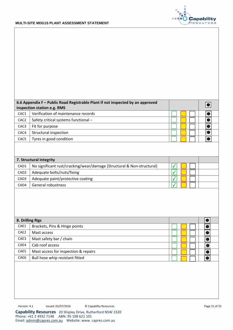
6.6 Appendix F – Public Road Registrable Plant if not inspected by an approved inspection station e.g. RMS CAC1 Verification of maintenance records CAC2 Safety critical systems functional – CAC3 Fit for purpose CAC4 Structural inspection CAC5 Tyres in good condition
7. Structural IntegrityCAD1 No significant rust/cracking/wear/damage (Structural & Non-structural) CAD2 Adequate bolts/nuts/fixing CAD3 Adequate paint/protective coating CAD4 General robustness
8. Drilling RigsCAE1 Brackets, Pins & Hinge points CAE2 Mast access CAE3 Mast safety bar / chain CAE4 Cab roof access CAE5 Mast access for inspection & repairs CAE6 Bull hose whip resistant fitted
✔
✔
✔
✔
●
●
●
●
●
●
●
●
●
●
●
●
●
Version: 4.1 Issued: 02/07/2016 © Capability Resources Page 22 of 25
MULTI-SITE MDG15 PLANT ASSESSMENT STATEMENT
Capability Resources 20 Shipley Drive, Rutherford NSW 2320 Phone: +61 2 4932 7148 ABN: 95 108 621 101 Email: [email protected] Website: www. capres.com.au
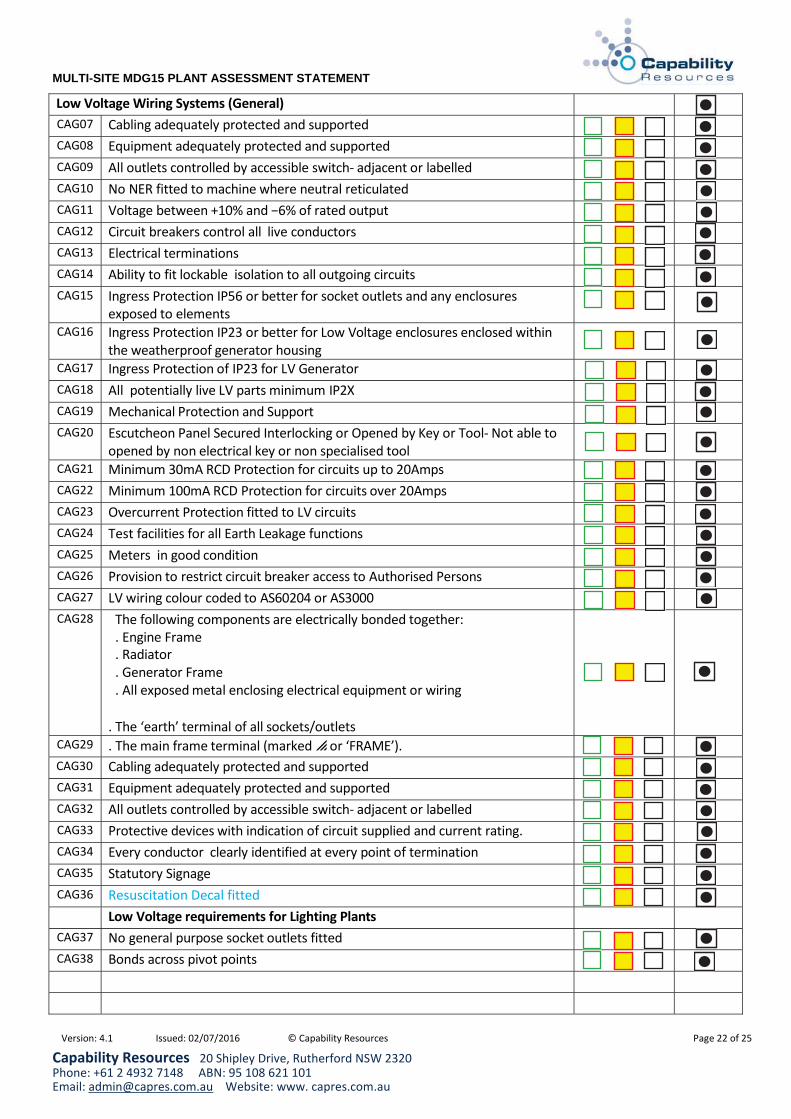
Low Voltage Wiring Systems (General) CAG07 Cabling adequately protected and supported CAG08 Equipment adequately protected and supported CAG09 All outlets controlled by accessible switch- adjacent or labelled CAG10 No NER fitted to machine where neutral reticulated CAG11 Voltage between +10% and 6% of rated output CAG12 Circuit breakers control all live conductors CAG13 Electrical terminations CAG14 Ability to fit lockable isolation to all outgoing circuits CAG15 Ingress Protection IP56 or better for socket outlets and any enclosures
exposed to elements
CAG16 Ingress Protection IP23 or better for Low Voltage enclosures enclosed within the weatherproof generator housing
CAG17 Ingress Protection of IP23 for LV Generator CAG18 All potentially live LV parts minimum IP2X CAG19 Mechanical Protection and Support CAG20 Escutcheon Panel Secured Interlocking or Opened by Key or Tool- Not able to
opened by non electrical key or non specialised tool
CAG21 Minimum 30mA RCD Protection for circuits up to 20Amps CAG22 Minimum 100mA RCD Protection for circuits over 20Amps CAG23 Overcurrent Protection fitted to LV circuits CAG24 Test facilities for all Earth Leakage functions CAG25 Meters in good condition CAG26 Provision to restrict circuit breaker access to Authorised Persons CAG27 LV wiring colour coded to AS60204 or AS3000 CAG28 The following components are electrically bonded together:
. Engine Frame
. Radiator
. Generator Frame
. All exposed metal enclosing electrical equipment or wiring
. The ‘earth’ terminal of all sockets/outlets
CAG29 . The main frame terminal (marked or ‘FRAME’). CAG30 Cabling adequately protected and supported CAG31 Equipment adequately protected and supported CAG32 All outlets controlled by accessible switch- adjacent or labelled CAG33 Protective devices with indication of circuit supplied and current rating. CAG34 Every conductor clearly identified at every point of termination CAG35 Statutory Signage CAG36 Resuscitation Decal fitted
Low Voltage requirements for Lighting Plants CAG37 No general purpose socket outlets fitted CAG38 Bonds across pivot points
●
●
●
●
●
●
●
●
●
●
●
●
●
●
●
●
●
●
●
●
●
●
●
●
●
●
●
●
●
●
●
●
●

Version: 4.1 Issued: 02/07/2016 © Capability Resources Page 23 of 25
MULTI-SITE MDG15 PLANT ASSESSMENT STATEMENT
Capability Resources 20 Shipley Drive, Rutherford NSW 2320 Phone: +61 2 4932 7148 ABN: 95 108 621 101 Email: [email protected] Website: www. capres.com.au
Version: 4.1 Issued: 02/07/2016 © Capability Resources Page 24 of 25
MULTI-SITE MDG15 PLANT ASSESSMENT STATEMENT
Capability Resources 20 Shipley Drive, Rutherford NSW 2320 Phone: +61 2 4932 7148 ABN: 95 108 621 101 Email: [email protected] Website: www. capres.com.au
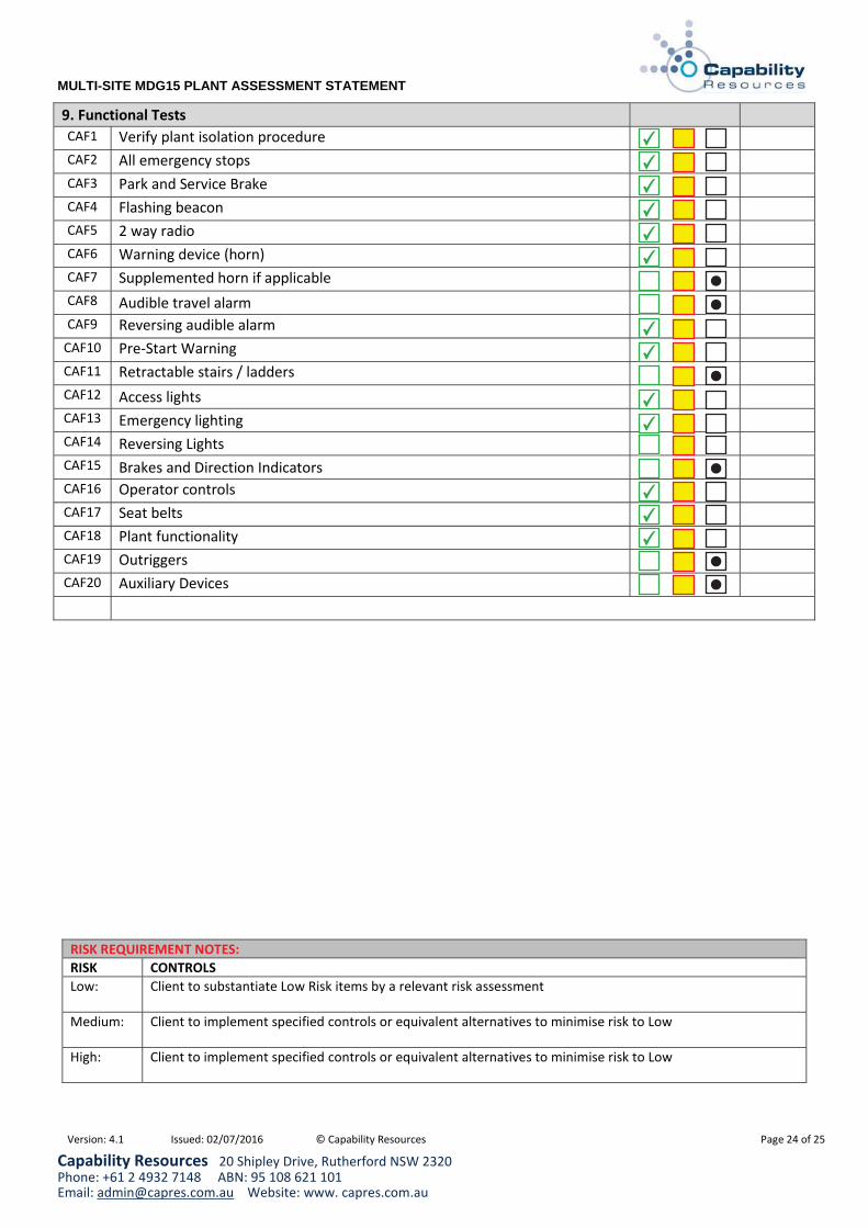
9. Functional Tests CAF1 Verify plant isolation procedure CAF2 All emergency stops CAF3 Park and Service Brake CAF4 Flashing beacon CAF5 2 way radio CAF6 Warning device (horn) CAF7 Supplemented horn if applicable CAF8 Audible travel alarm CAF9 Reversing audible alarm
CAF10 Pre-Start Warning CAF11 Retractable stairs / ladders CAF12 Access lights CAF13 Emergency lighting CAF14 Reversing Lights CAF15 Brakes and Direction Indicators CAF16 Operator controls CAF17 Seat belts CAF18 Plant functionality CAF19 Outriggers CAF20 Auxiliary Devices
RISK REQUIREMENT NOTES: RISK CONTROLS Low: Client to substantiate Low Risk items by a relevant risk assessment
Medium: Client to implement specified controls or equivalent alternatives to minimise risk to Low
High: Client to implement specified controls or equivalent alternatives to minimise risk to Low
✔
✔
✔
✔
✔
✔
✔
✔
✔
✔
●
●
●
✔
✔
✔
●
●
●
Version: 4.1 Issued: 02/07/2016 © Capability Resources Page 25 of 25
MULTI-SITE MDG15 PLANT ASSESSMENT STATEMENT
Capability Resources 20 Shipley Drive, Rutherford NSW 2320 Phone: +61 2 4932 7148 ABN: 95 108 621 101 Email: [email protected] Website: www. capres.com.au
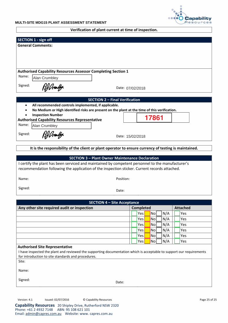
Verification of plant current at time of inspection.
SECTION 1 - sign off General Comments:
Authorised Capability Resources Assessor Completing Section 1Name:
Signed: Date:
SECTION 2 – Final Verification All recommended controls implemented, if applicable. No Medium or High identified risks are present on the plant at the time of this verification. Inspection Number
Authorised Capability Resources Representative Name:
Signed: Date:
It is the responsibility of the client or plant operator to ensure currency of testing is maintained.
SECTION 3 – Plant Owner Maintenance Declaration I certify the plant has been serviced and maintained by competent personnel to the manufacturer’s recommendation following the application of the inspection sticker. Current records attached. Name:
Position:
Signed: Date:
SECTION 4 – Site Acceptance Any other site required audit or inspection Completed Attached Yes No N/A Yes Yes No N/A Yes Yes No N/A Yes Yes No N/A Yes Yes No N/A Yes Yes No N/A Yes
Authorised Site Representative I have inspected the plant and reviewed the supporting documentation which is acceptable to support our requirements for introduction to site standards and procedures.Site:
Name: Signed: Date:
Alan Crumbley
Alan Crumbley
17861
07/02/2018
15/02/2018

Dozer
17861 07/02/2018
128 CAT00D8TCMLN00326
15/02/2018
Segregate engine bay wiring ✔
✔
✔
Fit "Emergency Exit" decal in cabin
Heat wrap turbo
C apability Resources 230 John Street (PO Box 551) Singleton NSW 2330 P hone: +61 2 6572 2332 Facsimile: +61 2 6572 2330 ABN: 95 108 621 101 Email: [email protected] Website: www. capres.com.au
Version: 3.9 Issued: 29/07/2013 © Capability Resources
.
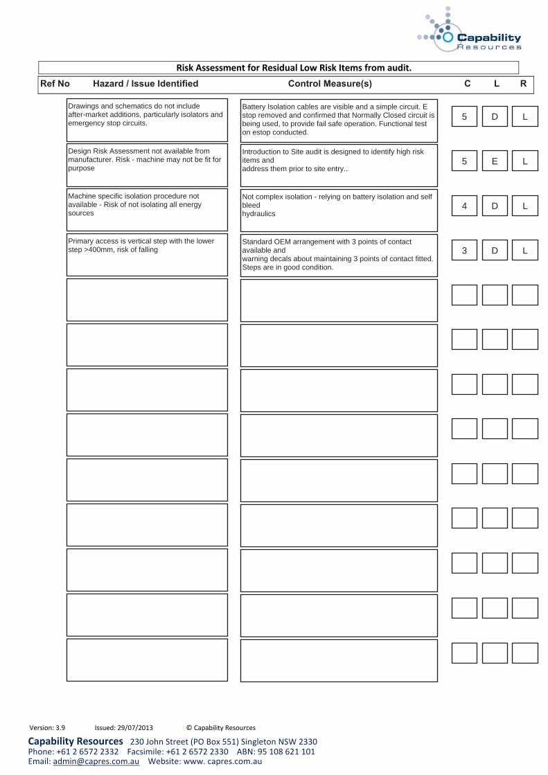
Drawings and schematics do not includeafter-market additions, particularly isolators andemergency stop circuits.
Battery Isolation cables are visible and a simple circuit. Estop removed and confirmed that Normally Closed circuit isbeing used, to provide fail safe operation. Functional teston estop conducted.
5 D L
5
4
3
E
D
D
L
L
L
Design Risk Assessment not available frommanufacturer. Risk - machine may not be fit forpurpose
Machine specific isolation procedure notavailable - Risk of not isolating all energysources
Primary access is vertical step with the lowerstep >400mm, risk of falling
Introduction to Site audit is designed to identify high riskitems andaddress them prior to site entry..
Not complex isolation - relying on battery isolation and selfbleedhydraulics
Standard OEM arrangement with 3 points of contactavailable andwarning decals about maintaining 3 points of contact fitted.Steps are in good condition.