multi-split system air conditioner - c-o-k.ru · multi-split system air conditioner indoor model no...
TRANSCRIPT

TECHNICAL & SERVICE MANUAL
SAP–KM97GHS5A( 2) + SAP–MC1827GH5SAP–KM97GHS5A/E( 2) + SAP–MC1827GH5
FILE NO.
REFERENCE NO. SM700252
Indoor Unit Outdoor Unit
MULTI-SPLIT SYSTEM AIR CONDITIONER
Indoor Model No Product Code No.
SAP–KM97GHS5A–S 1 852 659 06
Outdoor Model No. Product Code No.
SAP–MC1827GH5–S 1 852 753 90
SAP–KM97GHS5A/E–S 1 852 658 85 SAP–MC1827GH5–E 1 852 754 06
SAP–MC1827GH5
SAP–KM97GHS5ASAP–KM97GHS5A/E
i
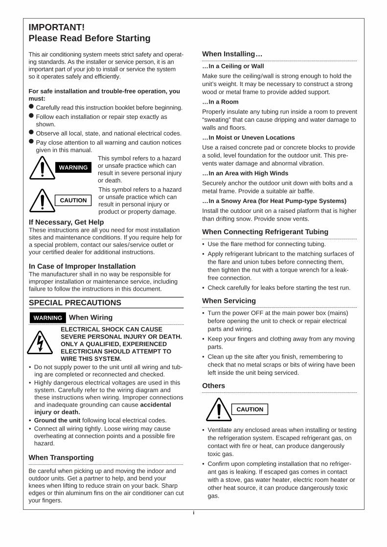
IMPORTANT! Please Read Before Starting
This air conditioning system meets strict safety and operat-ing standards. As the installer or service person, it is animportant part of your job to install or service the systemso it operates safely and efficiently.
For safe installation and trouble-free operation, youmust: Carefully read this instruction booklet before beginning. Follow each installation or repair step exactly as
shown. Observe all local, state, and national electrical codes. Pay close attention to all warning and caution notices
given in this manual.This symbol refers to a hazardor unsafe practice which canresult in severe personal injuryor death.
This symbol refers to a hazardor unsafe practice which canresult in personal injury orproduct or property damage.
If Necessary, Get HelpThese instructions are all you need for most installationsites and maintenance conditions. If you require help fora special problem, contact our sales/service outlet oryour certified dealer for additional instructions.
In Case of Improper InstallationThe manufacturer shall in no way be responsible forimproper installation or maintenance service, includingfailure to follow the instructions in this document.
SPECIAL PRECAUTIONS
When Wiring
ELECTRICAL SHOCK CAN CAUSESEVERE PERSONAL INJURY OR DEATH.ONLY A QUALIFIED, EXPERIENCEDELECTRICIAN SHOULD ATTEMPT TOWIRE THIS SYSTEM.
• Do not supply power to the unit until all wiring and tub-ing are completed or reconnected and checked.
• Highly dangerous electrical voltages are used in thissystem. Carefully refer to the wiring diagram andthese instructions when wiring. Improper connectionsand inadequate grounding can cause accidentalinjury or death.
• Ground the unit following local electrical codes.• Connect all wiring tightly. Loose wiring may cause
overheating at connection points and a possible firehazard.
When Transporting
Be careful when picking up and moving the indoor andoutdoor units. Get a partner to help, and bend yourknees when lifting to reduce strain on your back. Sharpedges or thin aluminum fins on the air conditioner can cutyour fingers.
When Installing…
…In a Ceiling or Wall
Make sure the ceiling/wall is strong enough to hold theunit’s weight. It may be necessary to construct a strongwood or metal frame to provide added support.
…In a Room
Properly insulate any tubing run inside a room to prevent“sweating” that can cause dripping and water damage towalls and floors.
…In Moist or Uneven Locations
Use a raised concrete pad or concrete blocks to providea solid, level foundation for the outdoor unit. This pre-vents water damage and abnormal vibration.
…In an Area with High Winds
Securely anchor the outdoor unit down with bolts and ametal frame. Provide a suitable air baffle.
…In a Snowy Area (for Heat Pump-type Systems)
Install the outdoor unit on a raised platform that is higherthan drifting snow. Provide snow vents.
When Connecting Refrigerant Tubing
• Use the flare method for connecting tubing.
• Apply refrigerant lubricant to the matching surfaces ofthe flare and union tubes before connecting them,then tighten the nut with a torque wrench for a leak-free connection.
• Check carefully for leaks before starting the test run.
When Servicing
• Turn the power OFF at the main power box (mains)before opening the unit to check or repair electricalparts and wiring.
• Keep your fingers and clothing away from any movingparts.
• Clean up the site after you finish, remembering tocheck that no metal scraps or bits of wiring have beenleft inside the unit being serviced.
Others
• Ventilate any enclosed areas when installing or testingthe refrigeration system. Escaped refrigerant gas, oncontact with fire or heat, can produce dangerouslytoxic gas.
• Confirm upon completing installation that no refriger-ant gas is leaking. If escaped gas comes in contactwith a stove, gas water heater, electric room heater orother heat source, it can produce dangerously toxicgas.
WARNING
WARNING
CAUTION
CAUTION

ii
Table of ContentsPage
Unit Combination........................................................................................................................ iv
1. OPERATING RANGE................................................................................................................... 1
2. SPECIFICATIONS
2-1. Unit Specifications................................................................................................................ 2
2-2. Major Component Specifications.......................................................................................... 4
2-3. Other Component Specifications.......................................................................................... 6
3. DIMENSIONAL DATA .................................................................................................................. 7
4. COOLING CAPACITY .................................................................................................................. 9
5. HEATING CAPACITY ................................................................................................................... 10
6. AIR THROW DISTANCE CHART................................................................................................. 11
7. REFRIGERANT FLOW DIAGRAM .............................................................................................. 12
8. ELECTRICAL DATA
8-1. Electrical Characteristics ...................................................................................................... 14
8-2. Electric Wiring Diagram........................................................................................................ 15
9. INSTALLATION INSTRUCTIONS
9-1. Installation Site Selection ..................................................................................................... 17
9-2. Remote Control Unit Installation Position ............................................................................. 19
9-3. Recommended Wire Length and Diameter .......................................................................... 20
10. FUNCTION
10-1.Room Temperature Control .................................................................................................. 21
10-2.Dry Operation ....................................................................................................................... 23
10-3.Freeze Prevention ................................................................................................................ 24
10-4.Overload Prevention............................................................................................................. 24
10-5.Cold draft Prevention............................................................................................................ 25
10-6.Defrosting Operation ............................................................................................................ 26
11. TROUBLESHOOTING
11-1.Check before and after troubleshooting ............................................................................... 28
11-1-1. Check power supply wiring....................................................................................... 28
11-1-2. Check inter-unit wiring.............................................................................................. 28
111-3. Check power supply ................................................................................................. 28
11-1-4. Check lead wires and connectors in indoor and outdoor units................................. 28
iii
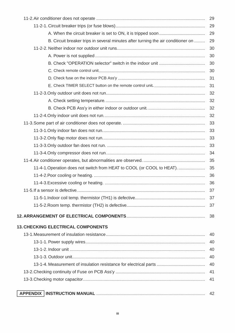
11-2.Air conditioner does not operate .......................................................................................... 29
11-2-1. Circuit breaker trips (or fuse blows).......................................................................... 29
A. When the circuit breaker is set to ON, it is tripped soon ...................................... 29
B. Circuit breaker trips in several minutes after turning the air conditioner on ......... 29
11-2-2. Neither indoor nor outdoor unit runs......................................................................... 30
A. Power is not supplied ........................................................................................... 30
B. Check "OPERATION selector" switch in the indoor unit ...................................... 30
C. Check remote control unit........................................................................................ 30
D. Check fuse on the indoor PCB Ass'y ........................................................................ 31
E. Check TIMER SELECT button on the remote control unit. .......................................... 31
11-2-3.Only outdoor unit does not run.................................................................................. 32
A. Check setting temperature. .................................................................................. 32
B. Check PCB Ass'y in either indoor or outdoor unit. ............................................... 32
11-2-4.Only indoor unit does not run.................................................................................... 32
11-3.Some part of air conditioner does not operate. .................................................................... 33
11-3-1.Only indoor fan does not run..................................................................................... 33
11-3-2.Only flap motor does not run..................................................................................... 33
11-3-3.Only outdoor fan does not run. ................................................................................. 33
11-3-4.Only compressor does not run.................................................................................. 34
11-4.Air conditioner operates, but abnormalities are observed. ................................................... 35
11-4-1.Operation does not switch from HEAT to COOL (or COOL to HEAT). ...................... 35
11-4-2.Poor cooling or heating. ............................................................................................ 36
11-4-3.Excessive cooling or heating. ................................................................................... 36
11-5.If a sensor is defective. ......................................................................................................... 37
11-5-1.Indoor coil temp. thermistor (TH1) is defective.......................................................... 37
11-5-2.Room temp. thermistor (TH2) is defective................................................................. 37
12. ARRANGEMENT OF ELECTRICAL COMPONENTS................................................................. 38
13. CHECKING ELECTRICAL COMPONENTS
13-1.Measurement of insulation resistance.................................................................................. 40
13-1-1. Power supply wires................................................................................................... 40
13-1-2. Indoor unit ................................................................................................................ 40
13-1-3. Outdoor unit.............................................................................................................. 40
13-1-4. Measurement of insulation resistance for electrical parts ........................................ 40
13-2.Checking continuity of Fuse on PCB Ass'y .......................................................................... 41
13-3.Checking motor capacitor..................................................................................................... 41
INSTRUCTION MANUAL .......................................................................................... 42APPENDIX

iv
Unit CombinationCombine indoor and outdoor units only as listed below.
Indoor Unit
Outdoor UnitA
B
Refer toOutdoor UnitSymbol ofIndoor Unit
SAP–MC1827GH5A
Indoor Unit
KM97
BFig.1
KM97
Fig.1

1
1. OPERATING RANGE
Temperature Indoor Air Intake Temp. Outdoor Air Intake Temp.
CoolingMaximum 35°C DB / 22°C WB 46°C DB
Minimum 19°C DB / 14°C WB 19°C DB
HeatingMaximum 27°C DB 24°C DB / 18°C WB
Minimum 16°C DB –8°C DB / –9°C WB

2. SPECIFICATIONS2-1. Unit Specifications
DATA SUBJECT TO CHANGE WITHOUT NOTICE.
Remarks: Rating conditions are:Cooling: Indoor air temperature 27°C DB/19°C WB
Outdoor air temperature 35°C DB/24°C WBHeating: Indoor air temperature 20°C DB
Outdoor air temperature 7°C DB/6°C WB
2
No. of indoor units. 1-unit
Power Source 220 – 240 V ~ 50 Hz
Cooling Heating
CapacitykW 2.60 / 2.60 / 2.65 3.25 / 3.25 / 3.30
BTU/h 8,900 / 8,900 / 9,000 11,100 / 11,100 / 11,300
Air circulation (High) m3/h 450
Moisture removal (High) Liters/h 1.1 —
Voltage rating V 220 / 230 / 240
Available voltage range V 198 to 264
Running amperes A 4.6 / 4.6 / 4.6 5.1 / 5.0 / 4.9
Power input W 990 / 1,010 / 1,040 1,090 / 1,090 / 1,090
Power factor % 98 / 95 / 94 97 / 95 / 93
C.O.P. W/W 2.6 / 2.6 / 2.5 3.0 / 3.0 / 3.0
Compressor locked rotor amperes A 23 / 24 / 25
Controls / Temperature control Microprocessor / I.C. thermostat
Control unit Wireless remote control unit
Timer 1-hour OFF / 12-hour ON or OFF
Fan speeds Indoor / Outdoor 3 and Auto / 1
Airflow direction (Indoor)Horizontal Manual
Vertical Auto
Air filter Washable, Anti–Mold
Compressor Rotary (Hermetic)
Refrigerant / Amount charged at shipment g R22 / 1,200
Refrigerant control Capillary tube
Operation soundIndoor – Hi / Me / Lo dB-A 40 / 34 / 31
Outdoor – Hi dB-A 53
Refrigerant tubing connections Flare type
Max. allowable tubing length at shipment m 7.5
Refrigerant tube Narrow tube mm (in.) 6.35 (1/4)diameter Wide tube mm (in.) 9.52 (3/8)
Refrigerant tube kit / Accessories Optional / Hanging wall bracket
Indoor Unit Outdoor Unit
Unit dimensions Height mm 265 630
Width mm 805 830
Depth mm 145 305
package dimensions Height mm 208 713
Width mm 855 994
Depth mm 326 413
Weight Net kg 7.5 61.0
Shipping kg 10.0 66.0
Shipping volume m3 0.06 0.29
Dim
ensi
ons
& W
eigh
tF
eatu
res
Ele
ctric
al R
atin
gP
erfo
rman
ce
Indoor Unit SAP–KM97GHS5A or SAP–KM97GHS5A /EOutdoor Unit SAP–MC1827GH5
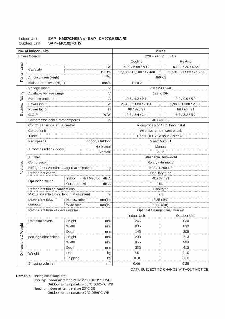
DATA SUBJECT TO CHANGE WITHOUT NOTICE.
Remarks: Rating conditions are:Cooling: Indoor air temperature 27°C DB/19°C WB
Outdoor air temperature 35°C DB/24°C WBHeating: Indoor air temperature 20°C DB
Outdoor air temperature 7°C DB/6°C WB
3
No. of indoor units. 2-unit
Power Source 220 – 240 V ~ 50 Hz
Cooling Heating
CapacitykW 5.00 / 5.00 / 5.10 6.30 / 6.30 / 6.35
BTU/h 17,100 / 17,100 / 17,400 21,500 / 21,500 / 21,700
Air circulation (High) m3/h 450 x 2
Moisture removal (High) Liters/h 1.1 x 2 —
Voltage rating V 220 / 230 / 240
Available voltage range V 198 to 264
Running amperes A 9.5 / 9.3 / 9.1 9.2 / 9.0 / 8.9
Power input W 2,040 / 2,080 / 2,120 1,980 / 1,980 / 2,000
Power factor % 98 / 97 / 97 98 / 96 / 94
C.O.P. W/W 2.5 / 2.4 / 2.4 3.2 / 3.2 / 3.2
Compressor locked rotor amperes A 46 / 48 / 50
Controls / Temperature control Microprocessor / I.C. thermostat
Control unit Wireless remote control unit
Timer 1-hour OFF / 12-hour ON or OFF
Fan speeds Indoor / Outdoor 3 and Auto / 1
Airflow direction (Indoor)Horizontal Manual
Vertical Auto
Air filter Washable, Anti–Mold
Compressor Rotary (Hermetic)
Refrigerant / Amount charged at shipment g R22 / 1,200 x 2
Refrigerant control Capillary tube
Operation soundIndoor – Hi / Me / Lo dB-A 40 / 34 / 31
Outdoor – Hi dB-A 53
Refrigerant tubing connections Flare type
Max. allowable tubing length at shipment m 7.5
Refrigerant tube Narrow tube mm(in) 6.35 (1/4)diameter Wide tube mm(in) 9.52 (3/8)
Refrigerant tube kit / Accessories Optional / Hanging wall bracket
Indoor Unit Outdoor Unit
Unit dimensions Height mm 265 630
Width mm 805 830
Depth mm 145 305
package dimensions Height mm 208 713
Width mm 855 994
Depth mm 326 413
Weight Net kg 7.5 61.0
Shipping kg 10.0 66.0
Shipping volume m3 0.06 0.29
Dim
ensi
ons
& W
eigh
tF
eatu
res
Ele
ctric
al R
atin
gP
erfo
rman
ce
Indoor Unit SAP–KM97GHS5A or SAP–KM97GHS5A /EOutdoor Unit SAP–MC1827GH5

2-2. Major Component Specifications
DATA SUBJECT TO CHANGE WITHOUT NOTICE.
Part No. POW–KM97GHS
Controls Microprocessor
Control circuit fuse 250 V – 3.15 A
Remote Control Unit RCS–7MHS1E
Type Cross–flow
Number ... Dia. and length mm 1 ... ø70 / L598
Fan motor model ... Number KFV2Q–11B5P ... 1
No. of poles ... rpm (230 V, High) 2 ... 1,900
Nominal output W 10
Coil resistance (Ambient temp. 20°C) Ω WHT – BRN : 385.3
WHT – VLT : 113.6
VLT – ORG : 37.4
ORG – YEL : 87.8
YEL – PNK : 95.8
Safety Type Internal thermal fuse
devices Operating temp.Open °C 145 ± 2
Close —
Run capacitorµF 1.0
VAC 440
Type Stepping motor
Model MP24GA1
Rating DC 12 V
Coil resistance (Ambient temp. 25°C) Ω WHT – BLU (respectively 4 wires) : 380 ± 7%
Coil Aluminum plate fin / Copper tube
Rows 2
Fin pitch mm 1.4
Face area m2 0.126
Hea
tE
xch.
Coi
lF
lap
Mot
orF
an &
Fan
Mot
orC
ontro
ller
PC
B
4
Indoor Unit SAP–KM97GHS5A or SAP–KM97GHS5A/E
5
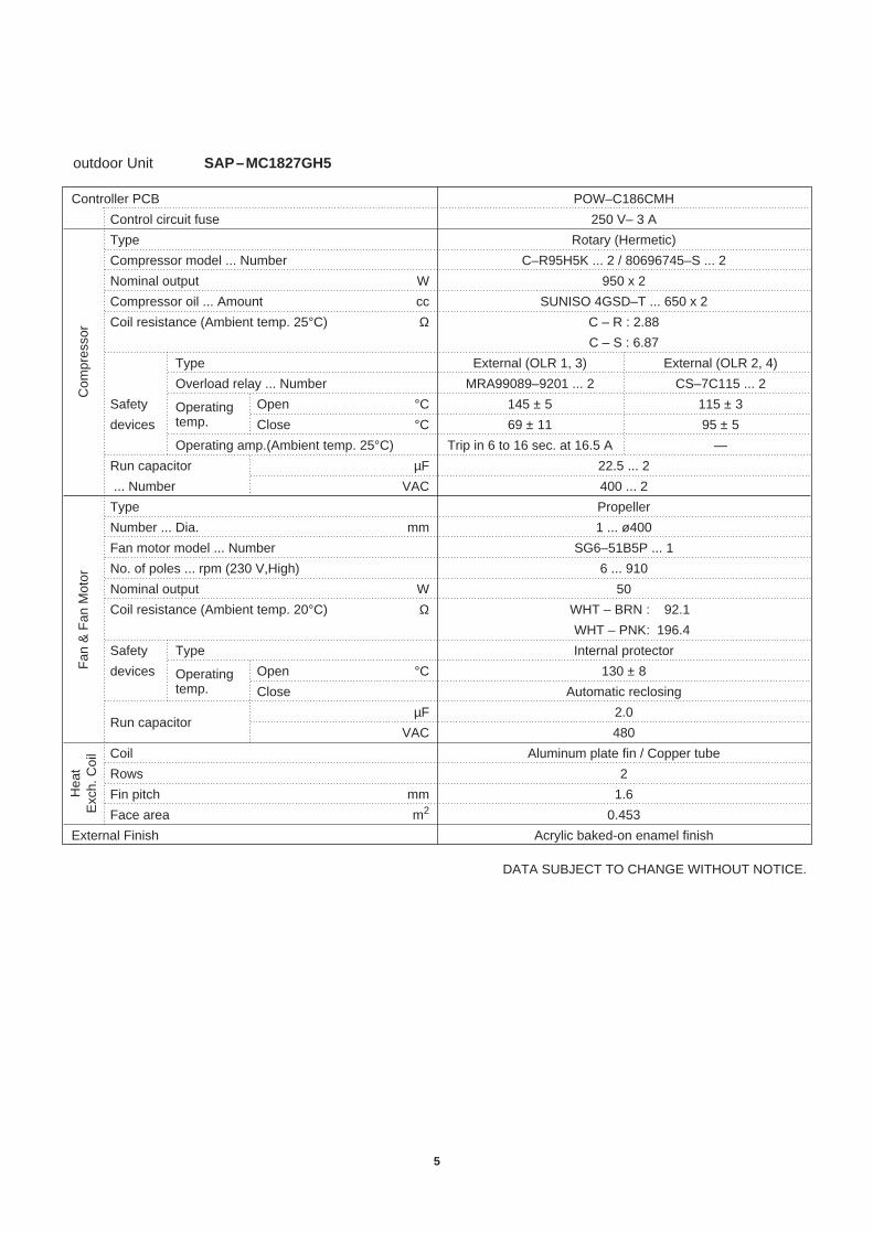
Controller PCB POW–C186CMH
Control circuit fuse 250 V– 3 A
Type Rotary (Hermetic)
Compressor model ... Number C–R95H5K ... 2 / 80696745–S ... 2
Nominal output W 950 x 2
Compressor oil ... Amount cc SUNISO 4GSD–T ... 650 x 2
Coil resistance (Ambient temp. 25°C) Ω C – R : 2.88
C – S : 6.87
Type External (OLR 1, 3) External (OLR 2, 4)
Overload relay ... Number MRA99089–9201 ... 2 CS–7C115 ... 2
Safety Operating Open °C 145 ± 5 115 ± 3
devices temp. Close °C 69 ± 11 95 ± 5
Operating amp.(Ambient temp. 25°C) Trip in 6 to 16 sec. at 16.5 A —
Run capacitor µF 22.5 ... 2
... Number VAC 400 ... 2
Type Propeller
Number ... Dia. mm 1 ... ø400
Fan motor model ... Number SG6–51B5P ... 1
No. of poles ... rpm (230 V,High) 6 ... 910
Nominal output W 50
Coil resistance (Ambient temp. 20°C) Ω WHT – BRN : 92.1
WHT – PNK: 196.4
Safety Type Internal protector
devices Operating Open °C 130 ± 8 temp. Close Automatic reclosing
Run capacitorµF 2.0
VAC 480
Coil Aluminum plate fin / Copper tube
Rows 2
Fin pitch mm 1.6
Face area m2 0.453
External Finish Acrylic baked-on enamel finish
Hea
tE
xch.
Coi
lC
ompr
esso
rF
an &
Fan
Mot
or
DATA SUBJECT TO CHANGE WITHOUT NOTICE.
outdoor Unit SAP–MC1827GH5

6
2-3. Other Component Specifications
Indoor Unit SAP–KM97GHS5A SAP–KM97GHS5A/E
Transformer (TR) ATR-J125
Rating Primary AC 230V, 50Hz
Secondary 19V, 0.631A
Capacity 12VA
Coil resistance Ω (at 21°C) Primary (WHT – WHT): 205 ± 10%
Secondary (BRN – BRN): 1.5 ± 10%
Thermal cut-off temp. 150°C
Thermistor (Coil sensor TH1) PBC-41E-S4
Resistance kΩ –20°C 40.1 ± 5% 20°C 6.5 ± 5%
–10°C 24.4 ± 5% 30°C 4.4 ± 5%
0°C 15.3 ± 5% 40°C 3.0 ± 5%
10°C 9.9 ± 5% 50°C 2.1 ± 5%
Thermistor (Room sensor TH2) DTN-TKS106E
Resistance kΩ 25°C 5.0 ± 3%
Outdoor Unit SAP–MC1827GH5
Power Relay (PRA, PRB) DFU24D1-F (M)
Coil rating DC 24V
Coil resistance Ω (at 20°C) 650 ± 10%
Contact rating AC 250V, 20A
Termistor (Coil sensor) PBC-41E-S15
Resistance kΩ –10°C 23.7 ± 5% 25°C 5.3 ± 5%
0°C 15.0 ± 5% 30°C 4.4 ± 5%
10°C 9.7 ± 5% 40°C 3.1 ± 5%
20°C 6.5 ± 5%
Solenoid Coil (4-way Valve SCA, SCB) CHV-01Ai038A1 (Coil), CHV-0101 (Valve)
Coil rating AC 230V, 50Hz, 5W
Coil resistance Ω (at 20°C) 1,408 ± 7%

7
3. DIMENSIONAL DATA
Outdoor Unit SAP–KM97GHS5A
SAP–KM97GHS5A/E
805 145
130
Center of tubing hole (3 places) Drain hose ø18
Narrow tube ø6.35 (1/4")
Rear panel (center point of gravity)
Wide tube ø9.52 (3/8")
124
58
42 4226
5
Remote control unit
18.557
161
Dimensions : mm

8
Outdoor Unit SAP–MC1827GH5
5858
9558
337
307
630
19
Narrow tube service valveø6.35(1/4")
1
Wide tube service valveø9.52(3/8")
2
305830
4 – ø12 holesAir discharge
Air intake
538 146
2
Magnified illustration
3 1
To Indoor Unit B
To Indoor Unit A
3 Check Port
Dimensions : mm

4. COOLING CAPACITY
9
Indoor Unit SAP–KM97GHS5A(x1) or SAP–KM97GHS5A/E(x1)
Outdoor Unit SAP–MC1827GH5
230 V Single phase 50 Hz
TC : Total Cooling Capacity (kW)SHC : Sensible Heat Capacity (kW)CM : Compressor Input (kW)
Rating conditions(#MARK) are: Outdoor Ambient Temp. 35°C D.B.: Indoor Unit Entering Air Temp. 27°C D.B. /19°C W.B.

5. HEATING CAPACITY
10
Indoor Unit SAP–KM97GHS5A or SAP–KM97GHS5A/E
Outdoor Unit SAP–MC1827GH5
–5 0 5 7 10 15
Outdoor temperature (°C DB)
0
10
20
30
40
50
60
70
80
90
100
110
120
Hea
ting
capa
city
rat
io (
%)
NOTE
1) … Point of Rating conditionBlack dot in the chart indicate the following rating condition.
Indoor : 20°C DBOutdoor : 7°C DB / 6°C WB
2) Above characteristics indicate instantaneous operation, which does not take into consideration defrost operation.
3) Fan speed : High
–8
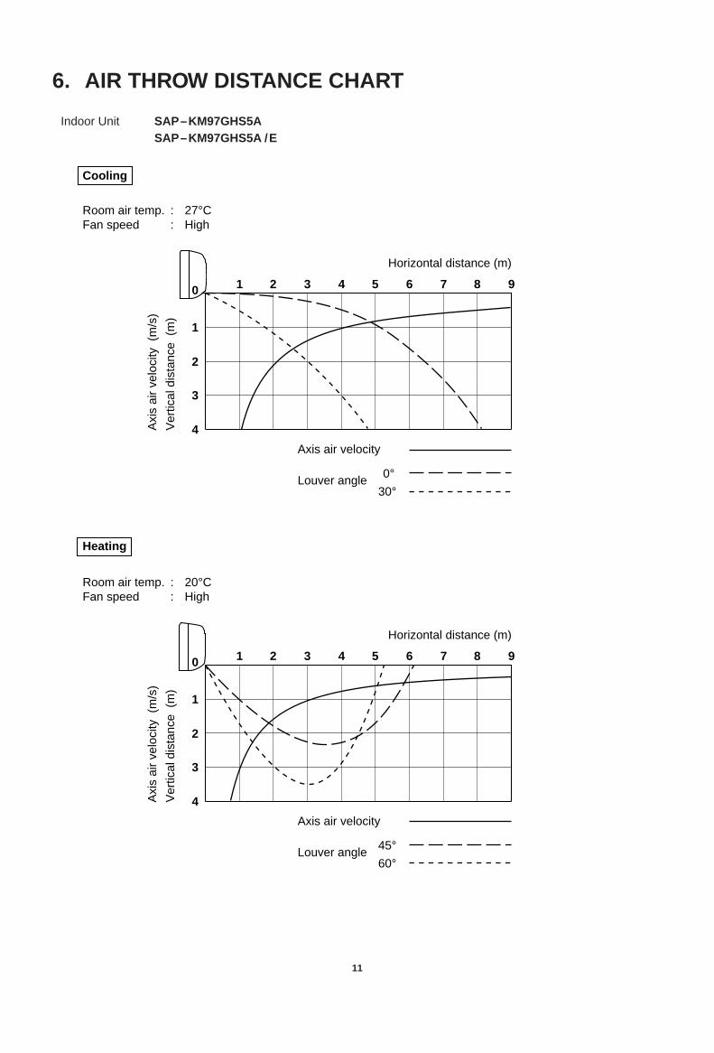
6. AIR THROW DISTANCE CHART
11
1 2 3 4 5 6 7 8 90
1
2
3
4
Horizontal distance (m)
Ver
tical
dis
tanc
e (
m)
Axi
s ai
r ve
loci
ty (
m/s
)
Room air temp.Fan speed
27°CHigh
::
Axis air velocity
Louver angle 0°
30°
1 2 3 4 5 6 7 8 90
1
2
3
4
Horizontal distance (m)
Ver
tical
dis
tanc
e (
m)
Axi
s ai
r ve
loci
ty (
m/s
)
Room air temp.Fan speed
20°CHigh
::
Axis air velocity
Louver angle 45°
60°
Heating
Cooling
Indoor Unit SAP–KM97GHS5ASAP–KM97GHS5A /E

7. REFRIGERANT FLOW DIAGRAM
12
Indoor Unit SAP–KM97GHS5A or SAP–KM97GHS5A/E
Outdoor Unit SAP–MC1827GH5
Hea
t exc
hang
er
Narrow tubeO. D.6.35mm(1/4")
Wide tubeO.D.9.52mm(3/8")
Muffler
Accumulator Compressor A
4–Way valve
4–Way valve
Drier ( )
Check valve
Strainer
Hea
t exc
hang
er
Narrow tubeO.D.6.35mm(1/4")
Wide tubeO.D.9.52mm(3/8")
Muffler
Accumulator Compressor B
Wide Tube Service valve
Narrow Tube Service valve
( )
Check valve
Strainer
Hea
t exc
hang
erCapillary tube
Checkport
Checkport
Indoor Unit A
Indoor Unit B
Drier
Cooling cycle

13
Hea
t exc
hang
er
Narrow tubeO.D.6.35mm(1/4")
Wide tubeO.D.9.52mm(3/8")
Muffler
Accumulator Compressor A
Capillarytube
( )
Check valve
Strainer
Hea
t exc
hang
er
Narrow tubeO.D.6.35mm(1/4")
Wide tubeO.D.9.52mm(3/8")
Muffler
Accumulator Compressor B
( )
Check valve
Strainer
Hea
t exc
hang
er
Checkport
Checkport
Indoor Unit A
Indoor Unit B
Wide Tube Service valve
Narrow Tube Service valve
Capillary tube
Drier
Drier
4–Way valve
4–Way valve
Insulation of Refrigerant Tubing
To prevent heat loss and wet floors due to dripping ofcondensation water, both the wide and narrow tubesmust be well insulated with proper insulationmaterial. The thickness of the insulation should be a min.8 mm.
After a tube has been insulated,never try to bend it into a narrowcurve because it can cause thetube to break or crack.
IMPORTANT
CAUTION
Wide tube
Thickness:Min. 8 mm
Insulation
Narrow tube
Thickness:Min. 8 mm
Heating cycle

8. ELECTRICAL DATA
8-1. Electrical Characteristics
The values in the table below indicate the sum of indoor and outdoor units which are in running condition.
14
NOTE
230V Single phase 50 Hz
Indoor Unit SAP–KM97GHS5A or SAP–KM97GHS5A/EOutdoor Unit SAP–MC1827GH5
Rating Conditions: Indoor Air Temperature 27°C DB / 19°C WBOutdoor Air Temperature 35°C DB
Full Load Conditions: Indoor Air Temperature 32°C DB / 23°C WBOutdoor Air Temperature 43°C DB
Number of indoor unit1 - Unit 2 - Units
(Either A or B) (Both A and B)
Rating ConditionsRunning amp. A 4.6 9.3
Power input kW 1.01 2.08
Full Load ConditionsRunning amp. A 6.0 12.2
Power input kW 1.30 2.72
Number of indoor unit1 - Unit 2 - Units
(Either A or B) (Both A and B)
Rating ConditionsRunning amp. A 5.0 9.0
Power input kW 1.09 1.98
Full Load ConditionsRunning amp. A 6.5 11.8
Power input kW 1.41 2.58
230V Single phase 50 Hz
Cooling
Heating
Rating Conditions: Indoor Air Temperature 20°C DBOutdoor Air Temperature 7°C DB / 6°C WB
Full Load Conditions: Indoor Air Temperature 27°C DBOutdoor Air Temperature 24°C DB / 18°C WB
Cooling
Heating

8-2. Electric Wiring Diagram
15
Indoor Unit SAP–KM97GHS5A SAP–KM97GHS5A/E

16
Outdoor Unit SAP–MC1827GH5

9. INSTALLATION INSTRUCTIONS
To prevent abnormal heat gen-eration and the possibility offire, don’t place obstacles,enclosures and grills in front ofor surrounding the air condi-tioner in a way that may blockair flow.
AVOID:
direct sunlight.
nearby heat sources that may affect performance ofthe unit.
areas where leakage of flammable gas may be expect-ed.
places where large amounts of oil mist exist.
DO: select an appropriate position from which every corner
of the room can be uniformly air-conditioned. (High ona wall is best)
select a location that will hold the weight of the unit.
select a location where tubing and drain pipe have theshortest run to the outside.
allow room for operation and maintenance as well asunrestricted air flow around the unit. (Fig. 2a)
Indoor Unit
5 cm
min.
5 cmmin.
5 cm min.
INDOOR UNIT
Front View
Wall-mounted Type Wall-Mounted Type
Front ViewFig.2a
WARNING
Minimum height from floor level 1.5m
Indoor Unit
Wall
Floor level
For stable operation ofthe air conditioner, donot install wall-mountedtype indoor units under1.5m from floor level.
CAUTION
Fig. 2b
9-1. Installation Site Selection
Maximum Allowable Tubing Length(L)and ElevationDifference(H).
The Multi-Split System outdoor unit should be installed asclose to the indoor units as possible. Maximum allowablelength of the refrigerant tubing and elevation differencebetween outdoor and indoor units are shown in Table 1.
Table 1
Combination Max allowable Limit of Limit of elevation Required amounttubing length tubing length(L). difference(H). of additional
Outdoor unit Indoor unit at shipment.(m) (m) (m) refrigerant*(g/m)
MC1827KM97
7.5 15 7 15KM97
* If total tubing length becomes 7.5 to 15 m (max.),charge additional refrigerant (R22) by 15 g/m.No additional charge of compressor oil is necessary.
17
INDOORUNIT
Tubing length (L)
OUTDOORUNIT
Less than elevationdifference (H) betweenthe 2 units
Fig. 1
18
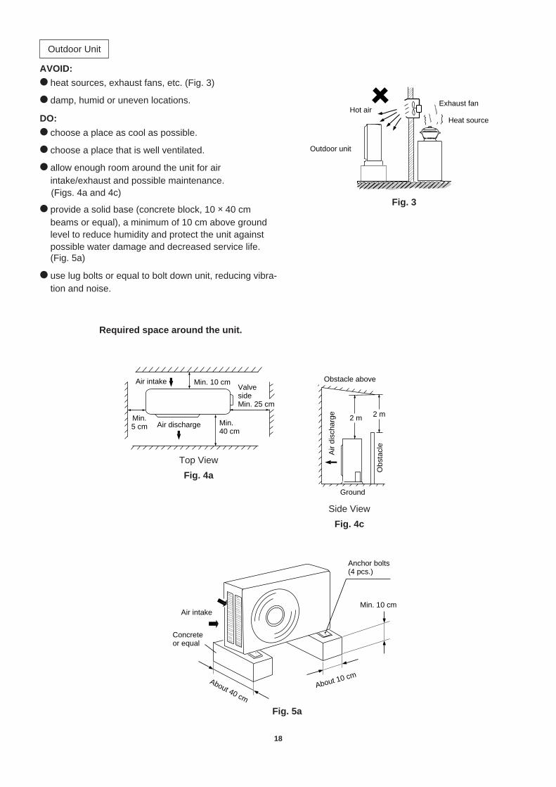
AVOID: heat sources, exhaust fans, etc. (Fig. 3)
damp, humid or uneven locations.
DO: choose a place as cool as possible.
choose a place that is well ventilated.
allow enough room around the unit for airintake/exhaust and possible maintenance.(Figs. 4a and 4c)
provide a solid base (concrete block, 10 × 40 cmbeams or equal), a minimum of 10 cm above groundlevel to reduce humidity and protect the unit againstpossible water damage and decreased service life.(Fig. 5a)
use lug bolts or equal to bolt down unit, reducing vibra-tion and noise.
Outdoor Unit
Outdoor unit
Hot airHeat source
Exhaust fan
Fig. 3Fig. 3
Air intake Min. 10 cm
Air dischargeMin.5 cm Min.
40 cm
ValvesideMin. 25 cm
Top View
Air intake
Concreteor equal
About 10 cm
Min. 10 cm
Anchor bolts(4 pcs.)
About 40 cm
Fig. 5 - A
2 m 2 m
Ground
Obs
tacl
eObstacle above
Air
disc
harg
e
Fig. 4 - C
Side View
Fig. 4c
Fig. 5a
Required space around the unit.
Top View
Fig. 4a

9-2. Remote Control Unit InstallationPosition
The remote control unit can be operated from either anon-fixed position or a wall-mounted position.
To ensure that the air conditioner operates correctly, donot install the remote control unit in the following places:
In direct sunlight
Behind a curtain or other place where it is covered
More than 8 m away from the air conditioner
In the path of the air conditioner's airstream
Where it may become extremely hot or cold
Where it may be subject to electrical or magnetic
interference
Mounting on a Wall
a) Removable mounting
1) Momentarily hold the remote control unit at thedesired mounting position.
2) Confirm that the air conditioner responds correctlywhen you press keys on the remote control fromthat position.
3) After confirming correct operation, use ascrewdriver to screw the supplied specialmounting screw into the wall. (Fig.6a)
4) Hang the remote control unit from the mountingscrew.
b) Non-removable mounting
1) Momentarily hold the remote control unit at thedesired mounting position.
2) Confirm that the air conditioner responds correctlywhen you press keys on the remote control fromthat position.
3) After confirming correct operation, use ascrewdriver to screw the supplied specialmounting screw into the wall. (Fig.6a)
4) Remove the remote control cover by sliding itdownward.
5) Remove the batteries of the remote control unit.
6) Use a screwdriver to screw the remote control unitsecuring screw into the wall through the hole in thebattery compartment. (Fig.6b)
7) Replace the batteries.
8) Again confirm that the remote control unit operatescorrectly.
19
Wall
Special mounting screw
Screw
Wall
Removable mounting
Fig.6b
Non-removable mounting
Fig.6a

Be sure to comply withlocal codes on running thewire from the indoor unit tothe outdoor unit (size ofwire and wiring method,etc.).
Each wire must be firmlyconnected.
No wire should be allowedto touch refrigerant tubing,the compressor, or anymoving part.
To avoid the risk of electricshock, each air conditionerunit must be grounded.
Be sure to connect thepower supply line to theoutdoor unit as shown inthe wiring diagram. Theindoor unit draws its powerfrom the outdoor unit.
Regulations on wiring diameter differ from locality to locality.For field wiring requirements, please refer to your local electrical codes. Carefully observe these regula-tions when carrying out the installation.Table 2 lists recommended wire lengths and size for powersupply systems.
Refer to the WIRING SYSTEM DIAGRAM for the meaning of"A", "B" and "C" in Table 2.
NOTE
20
WARNING
9-3. Recommended Wire Length and Diameter
WARNING
# ······ AWG (American Wire Gauge)
Table 2
(A) Power Supply Wiring Length (m) (B) Power Line Length (m) (C) Cont rol Line
2(#14)
3.5(#12)
2(#14)
MC1827 18 27 20 20
12
45
67
3
12
45
6
8
8
7
3
Outdoor unit
Terminal 8PAIndoorunit A
Terminal
220 V
Grounding line
Pow
erlin
eLo
w v
olta
geco
ntro
l lin
e
12
45
67
3
12
45
67
3
Terminal 8PBGrounding line
Pow
erlin
eLo
w v
olta
geco
ntro
l lin
e
Indoorunit B
Terminal2
3
1Power supplySingle-Phase, 50Hz, 220V
Grounding line
Ter
min
al3P
220 V
220 V220 V
B
B
C
CA
WIRING SYSTEM DIAGRAM
CAUTION
20A
Fuse or CircuitCapacity0.75
(#18)
Cross SectionalArea (mm2)
Model

10.FUNCTION
10-1. Room Temperature Control
Cooling
Room temperature control is obtained by cycling the compressor ON and OFF under control of the room
temperature sensor in the remote control unit.
The room temperature (and other information) is transmitted every 3 minutes by the remote control unit to the
controller in the indoor unit.
The control circuit will not attempt to turn the compressor ON until the compressor has been OFF for at least 3
minutes. To protect the compressor from stalling out when trying to start against the high side refrigerantpressure, the control circuit has a built-in automatic time delay to allow the internal pressure to equalize.
As a protective measure, the control circuit switches the compressor OFF after 5 minutes or more of compressor
operation.
Thermo. ON : When the room temperature is above T + 1°C (T°C is set temperature).Compressor ON
Thermo. OFF : When the room temperature is equal to or below set temperature T°C.Compressor OFF
21
3 minutes 3 minutes 3 minutes 3 minutes 3 minutes 3 minutes 3 minutes
3 minutes5 minutes
ON OFF ON OFF ON OFFCompressor
ON OFF ON OFF ON OFF
More than5 minutes
Outdoor fan
Indoor fan Set speed
T+1 °CT °Cset temp.
Thermo.OFF
Thermo.OFF
Thermo.ON
Thermo.OFF
Thermo.ON
Thermo.ON
Thermo.ON
Room temp.
Signal from remote control unit

Heating
Room temperature control is obtained by cycling the compressor ON and OFF under control of the room
temperature sensor in the remote control unit.
The room temperature (and other information) is transmitted every 3 minutes by the remote control unit to the
controller in the indoor unit.
The control circuit will not attempt to turn the compressor ON until the compressor has been OFF for at least 5
minutes. To protect the compressor from stalling out when trying to start against the high side refrigerantpressure, the control circuit has a built-in automatic time delay to allow the internal pressure to equalize.
As a protective measure, the control circuit switches the compressor OFF after 5 minutes or more of compressor
operation.
Thermo. ON : When the room temperature is below T – 1°C (T°C is set temperature).Compressor ON
Thermo. OFF : When the room temperature is equal to or above set temperature T°C.Compressor OFF
1: Refer to 10-5 "Cold Draft Prevention".
22
Set temp.
Signal from remote control unit
Outdoor fan
Compressor
ONON OFF OFF
OFFOFF
T°CT–1°CT–2°C
Room temp.
Thermo.ON
3 minutes 3 minutes 3 minutes 3 minutes 3 minutes 3 minutes
Thermo.OFF
Thermo.ON
Thermo.OFF
ONON
5 minutes
OFF
OFF
ON (Reversing cycle)
OFF LL LLOFF
OFF
Set speed
30 seconds
LL
30 seconds
LL
* 1
OFF
* 1
ONOFF
ON
OFF
OFF
Indoor fan
Standby lamp
Indoor heatexch. coiltemp. 35°C
Solenoid coil(4-way valve)
Operation button
5 minutes
* 1 25°C20°C
More than 5 minutes
ON
Set speed
ON
NOTE

10-2. Dry Operation (Dehumidification) Dry operation uses the ability of the cooling cycle to remove moisture from the air, but by running at low level to
dehumidify without greatly reducing the room temperature. The air conditioner repeats the cycle of turning ONand OFF automatically as shown in the chart below according to the room temperature.
23
NOTE
Room temp.
Cooling operation
T+2 °C
Set temp. T °C
T–1 °C
Monitor zone
Both the indoor and outdoor units stop.
Room temp. 15 °C
Dry A1 zone
Compressor :
FMI (indoor fan) :
Continuous operation
L (low speed) / LL (very low speed) intermittent ventilation only while the compressor is ON.
Dry B zone
Compressor :
FMI (indoor fan) :
Intermittent operation (ON for 3 minutes and OFF for 9 minutes)
L (low speed) / LL (very low speed) intermittent ventilation only while the compressor is ON.
Intermittent ventilation occurs by switching the indoor fan speed between L ↔ LL.
Dry operation does not occur when the room temperature is under 15°C, which is the monitor zone.
When the compressor stops, the indoor fan stops as well.

10-3. Freeze Prevention (Cooling) This function prevents freezing of the indoor heat exchange coil.
When the compressor has been running for 10 minutes or more and the temperature of the indoor heatexchange coil falls below –1°C, the control circuit stops the compressor for at least 6 minutes. The compressordoes not start again until the temperature rises above 8°C or 6 minutes has elapsed.
10-4. Overload Prevention (Heating) This function prevents overheating of the indoor heat exchange coil.
When the temperature of the indoor heat exchange coil rises above 54°C, and if the indoor fan is L (low speed),then the fan speed changes from L (low speed) to M (medium speed).
When the temperature of the indoor heat exchange coil rises above 57°C, the outdoor fan stops.
24
ON ON ON ONOFFOFF
Set speed
More than10 minutes
6 minutes
T+1 °C
Indoor heat exch. coil temp.
–1 °C
Compressor
Indoor fan
Room temp.Thermo. OFF
Thermo. ON
Set temp. T °C
More than10 minutes
More than6 minutes
Set speed
ONON OFF
ON
H or M or L H H H, M H M, L H M
5754
4744
Indoor heat exch. coil temp. °C
Outdoor fan
Indoor fan
Compressor

10-5. Cold draft Prevention (Heating) This function controls indoor fan speed so a strong draft of cold air will not blow out before the indoor heat
exchange coil have sufficiently warmed up.
STANDBY lamp on front of the indoor unit lights up when the indoor fan speed is either LL or OFF.
25
LL = Very low speedInitial start
Indoor heatexch. coiltemp. °C
ONCompressor
Indoor fan
Standby lamp
20°C
25°C
35°C
ON ON
LLLL Set speed
OFF
OFFOFF

10-6. Defrosting Operation (Heating)
Defrosting Flowchart.
26
* Split System A:
(= Cooling cycle)
Split System A (or B)
Heating operation
Defrosting starts.
Defrosting
Cold draft prevention
Defrosting stops.
Split System B (or A)
Temperature in outdoor heat exchangercoil drops 1 deg/6 min.or more and repeats3 times continuously.
Heating operation
20 minutes masking
6 minutes masking
Temperature in outdoor heat exchanger coil falls to –14°C or lower.
Preparation for defrosting
Temperature in outdoor heat exchanger coil is 26°C or higher.
Defrosting starts.
Cold draft prevention
Defrosting time is over 13.5 minutes.
Indoor unit ACompressor ASolenoid coil A
* Split System B: Indoor unit BCompressor BSolenoid coil B
Defrosting
Defrosting stops.
* *

Defrosting Mode Timing Chart
27
Standby lamp B
Indoor fan B
Indoor heatexch. coiltemp. 35°C
Light on OFFOFF
OFF*1
Light on
Set speed Set speed
Set speed Set speed
*1
OFF
OFF OFF
30 sec.
ON
ON
ON
5 sec.5 sec.
ON
ON
ON
ON
5 sec.
ON
ON
OFFOFF
OFF
OFF
OFF
1 min.
Defrosting 13.5 min. oroutdoor coil temp. 26°C
65 sec. 65 sec.
ON
Standby lamp A
Indoor fan A
Outdoor fan
4-way valveA and B
Compressor A
Compressor B OFF
NOTE *1. No LL fan operation during this period.
Release of defrosting
Start of defrosting
Unit AUnit B
Release of cold draft prevention

11.TROUBLESHOOTING
11-1. Check before and after troubleshooting
11-1-1.Check power supply wiring.
Check that power supply wires are correctly connect-
ed to terminals No.1 and No.2 on the 3p terminalplate in the outdoor unit.
11-1-2.Check inter-unit wiring.
Check that inter-unit wiring is correctly connected to
the indoor unit from the outdoor unit.
11-1-3.Check power supply.
Check that voltage is in specified range
(±10% of the rating).
Check that power is being supplied.
11-1-4.Check lead wires and connectors inindoor and outdoor units.
Check that coating of lead wires is not damaged.
Check that lead wires and connectors are firmly con-
nected.
Check that wiring is correct.
28
WARNING
Hazardous voltage can cause ELECTRICSHOCK or DEATH. Disconnect power or turnoff circuit breaker before you start checkingor servicing.
Outdoorunit
1
2
3
Ground
Indoorunit B
4
5
6
8
8
7
1
2Power supply:220V–240V~50Hz
Terminalplate B
1
2
3
4
5
6
7
Inter-unitpower wiring
Inter-unitcontrol wiring
1
2
3
Indoorunit A
4
5
6
7
Terminalplate A
1
2
3
4
5
6
7
Inter-unitpower wiring
Inter-unitcontrol wiring
29
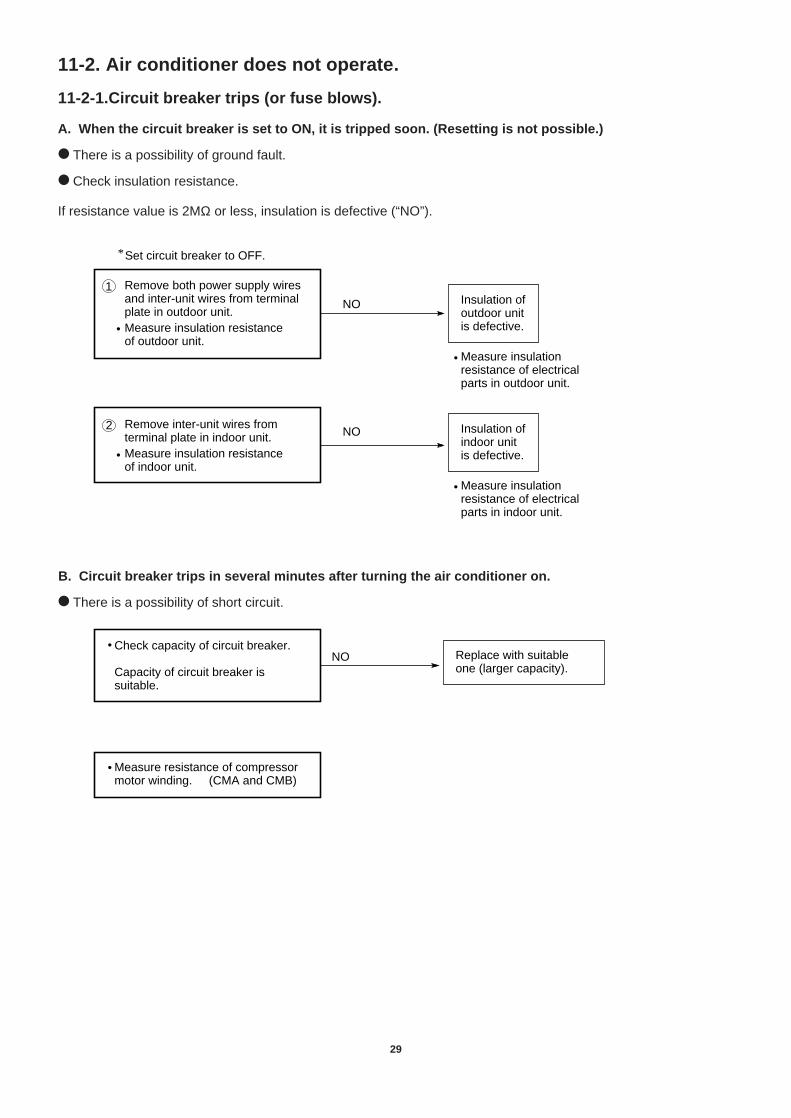
11-2. Air conditioner does not operate.
11-2-1.Circuit breaker trips (or fuse blows).
A. When the circuit breaker is set to ON, it is tripped soon. (Resetting is not possible.)
There is a possibility of ground fault.
Check insulation resistance.
If resistance value is 2MΩ or less, insulation is defective (“NO”).
B. Circuit breaker trips in several minutes after turning the air conditioner on.
There is a possibility of short circuit.
Measure insulationresistance of electricalparts in outdoor unit.
NO
NO
Set circuit breaker to OFF.*
Measure insulationresistance of electricalparts in indoor unit.
1 Remove both power supply wires and inter-unit wires from terminal plate in outdoor unit.Measure insulation resistanceof outdoor unit.
•
2 Remove inter-unit wires from terminal plate in indoor unit.Measure insulation resistanceof indoor unit.
•
•
•
Insulation of outdoor unit is defective.
Insulation of indoor unit is defective.
Replace with suitableone (larger capacity).
•NO
Check capacity of circuit breaker.
Capacity of circuit breaker is suitable.
• Measure resistance of compressor motor winding. (CMA and CMB)

30
11-2-2.Neither indoor nor outdoor unit runs.
A. Power is not supplied.
B. Check "OPERATION selector" switch in the indoor unit.
C. Check remote control unit.
NO• Check power supply.
Power is being supplied to the outdoor unit.
Circuit breaker is tripped.
Power failure
Reset breaker.
Wait for recovery or contact power company.
YES
NO
• OPERATION selector switch is set in ON position.
Set OPERATION selector switch to ON.
Switch Ass'y or indoor PCB Ass'y is defective.
OK
• Try to run with another remote control unit.
First remote control unit is defective.
• Check for residue buildup on transmitter of remote control unit.
• Check for residue buildup on remote control receiver on front of indoor unit.
Clean transmitter.
Clean receiver.

D. Check fuse on the indoor PCB Ass'y.
E. Check TIMER SELECT button on the remote control unit.
OK
Replace the fuse.
OK
OK
• Check fuse on indoor PCB Ass'y for continuity. (F)
• Check operation lamp to see if light is ON.
Light is OFF
• Measure resistance of primary and secondary winding of transformer. (TR)
Indoor PCB Ass'y or switch Ass'y is defective.
OK
• Measure resistance of indoor fan motor winding. (FMI)
• Measure resistance of flap motor winding. (FLP)
If fuse has been blown,
• Timer is turned ON. Check to see if "ON" is displayed on remote control
YES Press TIMER ON button to cancell the timer mode.
32
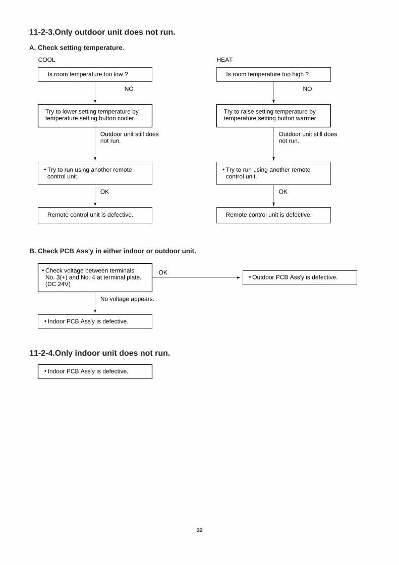
11-2-3.Only outdoor unit does not run.
A. Check setting temperature.
B. Check PCB Ass'y in either indoor or outdoor unit.
11-2-4.Only indoor unit does not run.
OK
NO
Is room temperature too low ?
Try to lower setting temperature by temperature setting button cooler.
Outdoor unit still does not run.
Remote control unit is defective.
• Try to run using another remote control unit.
COOL
OK
NO
Is room temperature too high ?
Try to raise setting temperature by temperature setting button warmer.
Outdoor unit still does not run.
Remote control unit is defective.
• Try to run using another remote control unit.
HEAT
• Indoor PCB Ass'y is defective.
• Check voltage between terminalsNo. 3(+) and No. 4 at terminal plate.(DC 24V)
No voltage appears.
• Outdoor PCB Ass'y is defective.OK
• Indoor PCB Ass'y is defective.

33
11-3. Some part of air conditioner does not operate.
11-3-1.Only indoor fan does not run.
11-3-2.Only flap motor does not run.
11-3-3.Only outdoor fan does not run.
Fan cannotbe turned.
OK
• Check fan rotation. Turn fan gently once or twice by hand.
• Check fan casing foreign matter on inside.
Fan motor burnout or foreign matter in bearings.
Remove foreign matter or repair.
Repair or replace.
• Measure resistance of indoor fan motor winding.
• Check fan motor capacitor.
Fan cannotbe turned.
Check fan casingfor foreign matteron inside.
Check fan rotation.Turn fan gently once or twiceby hand.
•
Measure resistance of outdoor fan motor winding.
•
OK
•
Fan motor burnoutor foreign matterin bearings.
Repair or replace.
Remove foreignmatter or repair.
Check fan motor capacitor. (CF)•
• Measure resistance of flap motor winding.

34
11-3-4.Only compressor does not run.
Measure resistance of compressor motor winding.
•
NO
Check compressor motor capacitor.
•
YES
YES
YES
Overload relay is working.
Refrigerant gas shortage. Charge refrigerant gas (R22).
Temperature of compressor is abnormally high.
Rotor may be locked up.
(OLR 1 to 4)(CA,CB)Measure coil resistance of power relay. (PRA,PRB)

35
11-4. Air conditioner operates, but abnormalities are observed.
11-4-1.Operation does not switch from HEAT to COOL (or COOL to HEAT).
• Indoor PCB Ass'y is defective.
• Check voltage between terminals No. 3(+) and No. 5 at terminal plate.
(DC 24V)
No voltage appears.
Outdoor PCB Ass'y is defective.OK
• Remote control unit may be defective.
• Measure resistance of 4–way valve's winding.
Receiver in switch Ass'y may be defective.
COOL HEAT
• Check voltage between terminals No. 3(+) and No. 5 at terminal plate.
(0V)
HEAT COOL
If unit A is stopped, unit B will switch to cooling or drying operation.
(Example) Unit A in heating modeUnit B in cooling or drying mode
Unit A in heating mode (Heating operation takes precedence.)Unit B fan operating
• If the units are operated in different modes (for example, unit A in the heating mode and unit B in the cooling ordrying mode), the results are as follows.
Units A and B cannot be operated in different modes simultaneously (for example,unit A operating in the heating mode while unit B is operating in the cooling ordrying mode). When operating two units at the same time, set them both to thesame mode. Note however that though technically different modes, unit A canoperate in the cooling mode while B is operating in the drying mode.
CAUTION

36
11-4-2.Poor cooling or heating.
11-4-3.Excessive cooling or heating.
Air filter is clogged.
NO
YES
Temperaturedifferenceis small.
YES
Temperature difference betweensuction and discharge air islarge enough (approx. 10 deg. or more).
Possibility ofgas shortage.
YES• Check position of remote control unit. Cool or warm air from air conditioner reaches position directly.
• Change position of remote control unit.
• Wide and narrow tubes between indoor unit and outdoor unit are insulated.
Insulate both wide and narrow tubes separately and then tape together.
• Measure temperature of suction and discharge air of air conditioner.
Charge refrigerant gas (R22).
Check for clogging of air filter.
• Fan speed is set to LOW.
Clean filter.
Set fan speed to either HIGH or MEDIUM.
• Review cooling load estimate, if performance of air conditioner is normal.
Reduce cooling or heating load or replace the air conditioner with larger capacity.
NOTE
NO
NO
• Set temperature is suitable.
Set temperature to higher or lower value using temperature setting buttons of the remote control unit.
• Remote control unit is placed where it can detect room temperature properly.
Change position of remote control unit.

37
11-5. If a sensor is defective.
11-5-1.Indoor coil temp. thermistor (TH1) is defective.
Alarm Signal (*)
Operation lamp on the front side of the indoor unit will flash on and off when the indoor coil thermistor is defective.(That is, sensor is SHORT). At the same time the outdoor unit will stop. Indoor unit will operate only for ventilation.
11-5-2.Room temp. thermistor (TH2) is defective.
A. Open
When thermistor opens, the air conditioner will be in the following conditions as the controller tries to detectextremely low room temperature.a) In Cooling mode: The air conditioner soon stops and will not start again. (Thermo.OFF)
Neither outdoor fan nor compressor runs.b) In Heating mode: The air conditioner continues to operate. (Thermo.ON)
Both the outdoor fan and compressor do not stop.As a result, the room becomes too warm.
B. Short
When thermistor is short, the air conditioner will be in the following conditions as the controller tries to detect extremely high room temperature.a) In Cooling mode: The air conditioner continues to operate. (Thermo.ON)
Both the outdoor fan and compressor do not stop.As a result, the room becomes too cold.
b) In Heating mode: The air conditioner soon stops and will not start again. (Thermo.OFF)Neither outdoor fan nor compressor runs.
Definition of Open or Short Circuit of Sensor (Thermistor)
Open...A lead wire is broken or disconnected or the circuit inside the temperature sensor is open .
Short... The protective cover of a lead wire has been damaged, and the exposed wire is touching another metalpart, or both lead wires have become exposed and are touching each other. Alternatively, the circuit insidethe temperature sensor is closed.
• Operation lamp on front side of indoor unit is flashing on and off. (*)
YES
• Replace thermistor.
• Thermistor (TH1 ) is defective. (That is, sensor is SHORT.)
No
• Function of freeze prevention continues to work in cooling mode.
YES
• Replace thermistor.
• Thermistor (TH1 ) is not connected to indoor PCB Ass'y, or its temperature sensor is defective. (That is, sensor is OPEN.)
No
Refer to 5-4 "Freeze Prevention"
NOTE
NOTE
Temperature sensor
Lead wires
Thermistor Structure

12. ARRANGEMENT OF ELECTRICAL COMPONENT
38
Room temp. thermistor (TH2) Fan motor capacitor (C)
Transformer (TR)
Terminal plate
PCB Ass'y
Switch Ass'y
Flap motor (FLP)
Coil temp. thermistor (TH1)
Electric Parts
Indoor Unit SAP–KM97GHS5ASAP–KM97GHS5A/E

39
PCB Ass'y
Compressor motor capacitor (CB)
Varistor (SA1)
Compressor motor capacitor (CA)
Fan motor capacitor (CF)
Overload relay (OLR3)Overload relay (OLR1)
Power relay B (PRB)
Power relay A (PRA)
Terminal Plate(To Power supply)
Terminal Plate(To Indoor Unit B)
Terminal Plate(To Indoor Unit A)
Varistor (SA2)
Compressor A (CMA)
Compressor B (CMB)
Solenoid coil A (SCA)Solenoid coil B (SCB)Fan motor
Heat exchenger coil
PCB Ass'y (Controller)
Electric Parts
Parts Layout in Unit
Thermistor
Outdoor Unit SAP–MC1827GH5

40
13-1. Measurement of Insulation Resistance
The insulation is in good condition if the resistance
exceeds 2MΩ.
13-1-1. Power Supply Wires
Clamp the ground wire of the power supply wires withthe lead clip of the insulation resistance tester and mea-sure the resistance by placing a probe on either of thepower wires. (Fig. 1)
Then measure the resistance between the ground wireand the other power wire. (Fig. 1)
13-1-2. Indoor Unit
Clamp an aluminum plate fin or copper tube with the leadclip of the insulation resistance tester and measure theresistance by placing a probe on each terminal screwexcept where the ground line is connected on the termi-nal plate. (Fig. 2)
13-1-3. Outdoor Unit
Clamp a metallic part of the unit with the lead clip of theinsulation resistance tester and measure the resistanceby placing a probe on each terminal screw where powersupply lines are connected on the terminal plate. (Fig. 2)
13-1-4. Measurement of InsulationResistance for Electrical Parts
Disconnect the lead wires of the desired electric partfrom terminal plate, capacitor, etc. Similarly disconnectthe connector. Then measure the insulation resistance.(Figs. 1 to 4)
Refer to Electric Wiring Diagram.
If the probe cannot enter the poles because the hole istoo narrow then use a probe with a thinner pin.
Insulation tester
Probe
Clip
Ground wire
Fig. 1
Terminal plate
Coppertube ormetallic part
Clip
Insulation tester
Probe
Fig. 2
Coppertube ormetallic part
Clip
Insulation tester
Probe
Fig. 3
Clip
Insulation tester
ProbeMetallic part
From fan motor,compressor and other parts
Fig. 4
13. CHECKING ELECTRICAL COMPONENTS
NOTE

41
13-2. Checking continuity of Fuse on PCB Ass'y
Check for continuity using a multimeter as shown in
Fig. 6.
Method Used to Replace Fuse on PCB Ass'y
— Indoor PCB Ass'y —
1. Remove the PCB Ass'y from the electrical component box
2. Then pull out the fuse from the PCB Ass'y.(Fig.5a)
— Outdoor PCB Ass'y —
1. Remove the PCB Ass’y from the electrical componentbox.
2. Pull out the fuse at the metal clasp using pliers whileheating the soldered leads on the back side of thePCB Ass'y with a soldering iron (30W or 60W).(Fig.5b)
3. Remove the fuse ends one by one. For replacementinsert a fuse of the same rating and solder it. (Allowtime to radiate heat during soldering so that the fusedoes not melt.)
13-3. Checking Motor CapacitorRemove the lead wires from the capacitor terminals, andthen place a probe on the capacitor terminals as shownin Fig. 7. Observe the deflection of the pointer, settingthe resistance measuring range of the multimeter to themaximum value.
The capacitor is “good” if the pointer bounces to a greatextent and then gradually returns to its original position.
The range of deflection and deflection time differ accord-ing to the capacity of the capacitor.
Multimeter
Ω
Compressor motor capacitor
Fan motorcapacitor
Fuse
PCB Ass’yIndoor
Fig. 5a
Fuse
Fig. 6
Fig. 7
Soldering iron
PCB Ass’yOutdoor
Fuse
Pliers
Fig. 5b
NOTE
42
INSTRUCTION MANUAL
Table of ContentsPage
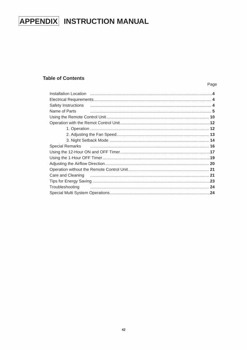
Installation Location ..........................................................................................................4Electrical Requirements...................................................................................................... 4Safety Instructions ......................................................................................................... 4Name of Parts ......................................................................................................... 5Using the Remote Control Unit......................................................................................... 10Operation with the Remot Control Unit..............................................................................12
1. Operation ....................................................................................................... 122. Adjusting the Fan Speed................................................................................ 133. Night Setback Mode ...................................................................................... 14
Special Remarks ....................................................................................................... 16Using the 12-Hour ON and OFF Timer..............................................................................17Using the 1-Hour OFF Timer .............................................................................................19Adjusting the Airflow Direction.......................................................................................... 20Operation without the Remote Control Unit...................................................................... 21Care and Cleaning ....................................................................................................... 21Tips for Energy Saving ......................................................................................................23Troubleshooting ....................................................................................................... 24Special Multi System Operations.......................................................................................24
APPENDIX

SANYO Electric Co.,Ltd
Osaka, Japan
SM700252 3/96/200
Printed in Japan
Ver. 1: KM97GHS5A–S + MC1827GH5–SKM97GHS5A/E–S + MC1827GH5–E