multi use tester iii second edition m.u.t.-iii se user's ... · multi use tester iii second...
TRANSCRIPT
Multi Use Tester III Second Edition
M.U.T.-III SE User's Manual
Ver.4.1

Foreword
This manual explains M.U.T.-III SE: functions, operating procedures, and other related information. By reading this manual you will obtain a basic understanding of M.U.T.-III SE and Vehicle Communication Interface-Lite (hereafter abbreviated as V.C.I.-Lite) functions and methods of operation. Because there are differences in M.U.T.-III SE methods of operation due to the vehicle electronic control system, be sure to read this manual and Online Help prior to operation. Please note that the information herein may not always agree with your version of the M.U.T.-III SE system due to system specification changes and version upgrades. Please take good care of this manual along with your M.U.T.-III SE product.
M.U.T.-III User's Manual

Table of Contents Chapter 1 Product Overview ........................................................................................ 1
1-1. Precautions ............................................................................................................................... 1
1-2. V.C.I.-Lite Outline Drawing and Component Names ................................................................. 2
1-3. M.U.T.-III SE Components Explanations ................................................................................... 3
1-4. Harness Connection Method .................................................................................................... 4
Chapter 2 M.U.T.-III SE Functions ................................................................................ 5
Chapter 3 Starting and Shutting the M.U.T.-III SE System......................................... 6
3-1. Starting and Shutting the M.U.T.-III SE System ........................................................................ 6
3-2. Screen Explanations ................................................................................................................. 7
3-3. Basic Flow to Start Diagnosis ................................................................................................. 11
3-4. M.U.T.-III SE Option Settings .................................................................................................. 14
3-5. Useful Functions ..................................................................................................................... 15
Chapter 4 Diagnosis Function ................................................................................... 16
4-1. Diagnostic Trouble Code ........................................................................................................ 16
4-2. Data List (Service Data monitor) ............................................................................................. 17
4-3. Actuator Test ........................................................................................................................... 21
4-4. All DTCs .................................................................................................................................. 23
Chapter 5 Drive Recorder ........................................................................................... 25
5-1. How to Record the Data ......................................................................................................... 25
5-2. Recorded Data Handling ........................................................................................................ 30
5-3. Analysis of the Recorded Data................................................................................................ 33
Chapter 6 CAN Bus Diagnosis ................................................................................... 34
6-1. Diagnosing the CAN Bus ........................................................................................................ 34
Chapter 7 Computer Diagnosis ................................................................................. 35
7-1. Operation method of MiEV Computer Diagnosis .................................................................... 35
7-2. Operation method of PHEV Computer Diagnosis ................................................................... 41
Chapter 8 ECU Reprogramming ................................................................................ 45
8-1. ECU Reprogramming(SDB) ............................................................................................... 45
8-2. Trouble of Reprogramming ..................................................................................................... 48
Chapter 9 How to Use (Special Case) ....................................................................... 49
9-1. Copy Coding ........................................................................................................................... 49
9-2. Chassis No. / VIN Writing and Chassis No. / VIN Information ................................................ 50
9-3. Coding Operation .................................................................................................................... 54
9-4. Customization Operation ........................................................................................................ 58
Chapter 10 Reference Material .................................................................................. 61
M.U.T.-III User's Manual

10-1. V.C.I.-Lite Electrical Properties ............................................................................................. 61
Appendix ..................................................................................................................... 62
<< Copyright belonging >> ............................................................................................................. 62

For Your Safety
To ensure proper use of this product and prevent personal injury and property damage, various graphic displays are used in the user’s manual. The graphic displays and respective meanings are described below.
Warning messages alert you to a procedure or practice which, if not
followed correctly, could lead to death or serious injury.
Caution messages alert you to a procedure or practice which, if not followed correctly, could lead to serious injury and/or property damage.
Drivers should not operate the unit while driving. • Operating the unit while driving may result
in a traffic accident.
Do not plug in or unplug the power AC adapter with wet hands. • Doing so results in the risk of electric shock.
Do not use the unit if the power AC adapter plug or cord is damaged or plugging into the outlet is loose • Use under such conditions may result in
electric shock, an electric short and/or fire.
Be sure to hold the harness connector when disconnecting from the vehicle. Do not disconnect the harness by pulling on the cord. • Pulling the cord rather than the connector
may result in damage to the lead wire inside the cord, thereby causing a short and possibly starting a fire.
Unplug the power AC adapter from the outlet when the unit is not in use. • Failure to do so may result in injury, burns,
electric shock caused by insulation deterioration, or fire due to a short circuit.
Warning
Caution
Warning
Caution
For Your Safety

When the harness is connected to the V.C.I.-Lite, be sure to check the top and bottom of the connector and connect the harness perpendicularly to the connector of the V.C.I.-Lite. Connecting at an angle may result in bending of the pins of the connector. Check for the secure connection of the harness before tightening of the screw locks. The bent pin may contact the connector case, thereby causing an electric short which leads to damage to the V.C.I.-Lite. Do not remove the USB connector by pulling on the cable. * Excessive force in the direction of the arrow is likely to cause damage
to the USB connector terminal.
Do not apply excessive pressure to the USB cable and the terminal when connecting the main harness. * Excessive force in the direction of the arrow is likely to cause damage
to the USB connector terminal. Connect the main harness gently in order to avoid excessive pressure to the USB plug. * Excessive force in the direction of the arrow is likely to cause damage
to the USB connector terminal. Do not pull on the USB cable. * Excessive force in the direction of the arrow is likely to cause damage
to the USB connector terminal. Do not drop or hit against the wall. Also handle with care in order not to cause unexpected damage to the USB plug when you put the V.C.I.-Lite with connecting cable on the work benches.
For Your Safety
Caution

Do not expose the PC or V.C.I.-Lite to direct sunlight or high temperatures, or leave the unit in sun-heated cars. Such action may result in system failure.
Store the PC and V.C.I.-Lite in a dry environment at room temperatures.
Moving the PC and V.C.I.-Lite to a location with a very different temperature and humidity than that of the previous location may result in external or internal condensation. Caution is required.
Protect the PC and V.C.I.-Lite from exposure to elements such as rain, dirt, dust, food and liquids. (Recommend to be used with V.C.I.-Lite cover)
Be careful when handling the PC and V.C.I.-Lite Dropping the units may result in damage. (Recommend to be used with V.C.I.-Lite cover)
Do not expose either unit to engine oil, gasoline, antifreeze or battery acid. Also, do not clean the PC or V.C.I.-Lite case using solutions such as thinner or benzene. Doing so may result in deterioration of the case surface.
Prior to connecting the M.U.T.-III main harness between the V.C.I.-Lite and vehicle, turn the IG switch/Engine switch/Power switch to OFF. • Connecting the V.C.I.-Lite harness with the IG switch/Engine switch/Power switch ON may
damage the V.C.I.-Lite programming. Use only the power AC adapter included with the PC (or approved replacement), power cigarette plug, other probes, main harness and other cables. • Use of unspecified parts may result in damage or malfunction due to excess voltage or insufficient
contact. Keep all V.C.I.-Lite connectors and openings away from dirt and static electricity. Exposure to dirt and static electricity may result in malfunction and damage.
For Your Safety
Please Note

1
Chapter 1 Product Overview 1-1. Precautions
Service Work Precautions
• Be sure to follow all basic service work precautions when using M.U.T.-III SE during vehicle
inspection and service work. • For detailed information regarding service work precautions, refer to the service instruction
manual of each vehicle.
Work Precautions
• When performing vehicle inspection work at the work site with the engine running, either use an exhaust gas discharger or ventilate the area sufficiently.
• When working on a vehicle, be sure to apply the parking brake and set wheel chocks in place to prevent the car from moving.
Driving Precautions
• If you wish to use M.U.T.-III SE while driving the target vehicle, first verify that all parts are properly assembled.
• While driving, always have an assistant operate M.U.T.-III SE. • Be sure that the M.U.T.-III main harness and other cables will not interfere with driving. • Install and remove the PC and V.C.I.-Lite with the vehicle parked, IG switch/Engine
switch/Power switch OFF.
Precautions

2
1-2. V.C.I.-Lite Outline Drawing and Component Names The names of the V.C.I.-Lite components are indicated in the figure below.
M.U.T.-III main harness A for Lite
(MB992745)
USB cable for Lite
(MB992747, MB992748)
<<Component Names>>
1. Main harness terminal
2. Indicator lamp
3. USB terminal
V.C.I.-Lite Outline Drawing and Component Names
1
2
3
3
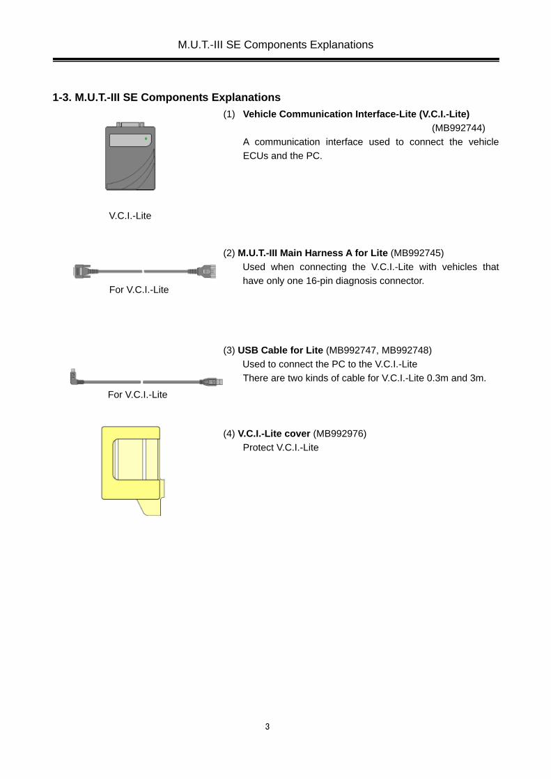
1-3. M.U.T.-III SE Components Explanations (1) Vehicle Communication Interface-Lite (V.C.I.-Lite)
(MB992744) A communication interface used to connect the vehicle ECUs and the PC.
(2) M.U.T.-III Main Harness A for Lite (MB992745)
Used when connecting the V.C.I.-Lite with vehicles that have only one 16-pin diagnosis connector.
(3) USB Cable for Lite (MB992747, MB992748) Used to connect the PC to the V.C.I.-Lite There are two kinds of cable for V.C.I.-Lite 0.3m and 3m.
(4) V.C.I.-Lite cover (MB992976) Protect V.C.I.-Lite
M.U.T.-III SE Components Explanations
For V.C.I.-Lite
For V.C.I.-Lite
V.C.I.-Lite

4
1-4. Harness Connection Method
Harness Connection Method
Recommended harness connection sequence [1] Start the PC. [2] Align the USB plug and USB terminal, then connect the USB plug carefully.
(See Figure 1, Figure 2) [3] Connect the USB cable to the PC. [4] Select the appropriate M.U.T.-III main harness. Connect it to the V.C.I.-Lite [5] Connect the M.U.T.-III main harness to the vehicle diagnosis connector. See Figure 3.
Note: Disconnect the harnesses by performing the above steps in the reverse order. [6] V.C.I.-Lite please make sure that the indicator lamp lights in green. [7] Turn the vehicle ignition switch/Engine switch/Power switch ON, and begin the diagnostic
process from the M.U.T.-III SE system screen
* In case the difference between the version installed in the PC and the version of firmware for V.C.I.-Lite is found, the updating process of V.C.I.-Lite begins. If updating error (the indicator lamp blinks) occurs on V.C.I.-Lite, it will be restarted with reconnection.
[5] [2] [3] [4] [6] [7]
[1]
<Fig. 3> <Fig. 1>
<Fig. 2>

5
Chapter 2 M.U.T.-III SE Functions
Function Synopsis
DTC readout
Reads various diagnostic codes and displays the codes by name and number.
Data List
Reads RAM data inside ECU and displays the data in digital and graphic form. (Available with ECUs that support serial communication only)
Actuator tests
Permits forced operation or shutdown of various types of actuators that is required for service.
(Available with ECUs that support serial communication only)
* In case out of vehicles and functions applied with M.U.T.-III SE, operate with M.U.T.-III the same as
always.
M.U.T.-III SE Functions

6
Chapter 3 Starting and Shutting the M.U.T.-III SE System 3-1. Starting and Shutting the M.U.T.-III SE System
3-1-1. Starting the M.U.T.-III SE System Double-click the M.U.T.-III SE icon displayed on the desktop to start up the system.
3-1-2. Shutting Down the M.U.T.-III SE System
Click Exit button at the lower right of Top screen. Also click button to close the system at the upper right on any screen. When close with button, the confirmation dialog appears, then click button.
Starting and Shutting the M.U.T.-III SE System
[M.U.T.-III SE icon]

7
3-2. Screen Explanations 3-2-1. TOP Screen
Screen Explanations
Starts “Scan Tool Viewer (STV)” system. This manual contains information for proper operation of this system. Click this button first to start various interactive diagnoses.
Exits the M.U.T.-III SE system.
Shows “M.U.T.-III SE User's Manual”.
Set configuration for M.U.T.-III SE. (refer to 3-4.)
Changed functions in this version-up are mentioned. Clicking What’s New button can find more details
Useful tips are mentioned. Clicking Topics button can find more details.
M.U.T.-III SE Version is shown.

8
3-2-2. Tab Function
• A tab shown in a greyout state is out of function. • Click button on a tab, it will close. • When click button after changing the vehicle information or diagnosis system by returning to
System select screen with a tab during your diagnosis operation, the confirmation dialog of tab reset appears. Clicking button can close all tabs.
Screen Explanations
Showing a title enables you to find what you do in which system. A screen can be changed by clicking a tab.
Click button to change screen to be displayed.

9
3-2-3. Change screen size Click button at the upper right of M.U.T.-III SE screens, it changes from full screen to window screen.
Change screen size by dragging a corner of screen in window mode. Also move screen by dragging on the part of title bar in window mode.
Click button at the upper right of screen in window mode, it becomes full screen.
Screen Explanations
Title bar

10
Click button at the upper right of M.U.T.-III SE screens, it is minimized. By clicking the icon of M.U.T.-III SE on the taskbar, it is displayed again.
3-2-4. Function keys Each button located in the bottom of M.U.T.-III SE corresponds to the key from F1 to F10 on the keyboard.
Screen Explanations
Task bar
F1 F2 F3 F4 F5 F6 F7 F8 F9 F10

11
3-3. Basic Flow to Start Diagnosis 3-3-1. Basic Flow of System Select Diagnosis
(1) M.U.T.-III SE TOP Screen Click STV button on the M.U.T.-III SE TOP Screen.
* Click STV button with connecting the vehicle, then read VIN of the vehicle and input VIN and Vehicle information into the column automatically. (refer to 3-3-3.)
(2) System Selection Select the vehicle information on the right of the screen and a system to be checked on the left, then click button. (refer to 3-3-2.) A system shown in a greyout state means out of support with M.U.T.-III SE, then diagnose with M.U.T.-III.
---CAN Bus Diagnosis (refer to Chapter 6) --- All DTCs (refer to 4-4.) --- ECU reprogramming (refer to Chapter 8) --- Data view for Drive Recorder (refer to 5-2-1.) Computer Diagnosis (refer to Chapter 7.) --- Diagnosis (refer to Chapter 4)
Same action as double-click a system is expected. --- VIN search (refer to 3-3-3.) --- Clear vehicle information (refer to 3-3-2.)
(3) Function Selection Screen
After System selection, the Function selection menu of the selected system appears. Select a button that you want to perform. In the picture on the left shows the screen appears when the MPI/GDI/DIESEL system, which is a representative example, is selected. Details of each buttons are as follows.
Note: As available functions differ between systems, there might be functions that will not appear when you select other system.
Basic Flow to Start Diagnosis

12
Self-diagnosis -- To read out or erase Diagnosis Trouble Codes from vehicle ECU.
Also, you can read out the Freeze Frame data. (refer to 4-1.) Data List -- To read the RAM data inside the ECU and displays the data in digital and graphic
form. (refer to 4-2.) Actuator Test -- To control the ECU output device. (refer to 4-3.) Drive Recorder -- To record, display or analyze the ECU input / output signals which can be
viewed using Data List function. (refer to Chapter 5) Special Function -- To execute special functions specific to the selected system.
Basic Flow to Start Diagnosis

13
3-3-2. Vehicle Information Setting • Currently selected information is displayed in each item’s field.
(Blank space means the information is not selected.) • Click button to delete whole information and select item
by item if you need to change the vehicle information. • When a table for equipped option (*a) is shown, set the right
option according to the vehicle specification. (Note) The item where a background is colored in pink in
no-setting is essential to input.
3-3-3. Function of vehicle recognition by Chassis No /VIN
• Click button, Chassis No/VIN is automatically read from the vehicle, retrieve vehicle information and input into the column. Manual input of the VIN with [Enter] key is also available.
(Only vehicles corresponds to VIN search) When Chassis No/VIN is not read, the left figure appears. In case there might be a difference between the selected vehicle information and input VIN, a background is colored in blue and shows Mismatch. Vehicles corresponds to VIN search
Destination Period
EU 05MY till M.U.T.-III SE master completed
Japan/EXP/MMAL 06MY till M.U.T.-III SE master completed
MMNA 05MY till M.U.T.-III SE master completed + before 05MY models applied CAN Bus Diagnosis
3-3-4. Out of Vehicles/Functions applied with M.U.T.-III SE
• In case out of support in vehicles and functions with M.U.T.-III SE the dialog of left figure appears, then operate with M.U.T.-III instead. Click button and M.U.T.-III starts. (This button is not displayed in US)
Basic Flow to Start Diagnosis
*a

14
3-4. M.U.T.-III SE Option Settings 3-4-1. Select M.U.T.-III SE Option Settings
(1) Click Configuration button on the lower middle of Top Screen.
(2) Following items can be set in the setting screen. Click Save and Close button after setting
- Font size You can confirm a real font size in a preview window on the right side.
- Display unit - Display language
M.U.T.-III SE Option Settings

15
3-5. Useful Functions 3-5-1. Display “M.U.T.-III SE User's Manual”
Click M.U.T.-III Manual button at the lower left of Top Screen. (refer to 3-2.) Click button at the upper right to close the manual.
3-5-2. Print Function Possible to print in the style of Screen or Data with button in the screen of each function. • Print screen
Print the image shown on the screen. • Print list
Print the value in each function with List-style.
e.g. Print list : FFD Print list
Useful Functions

16
Chapter 4 Diagnosis Function 4-1. Diagnostic Trouble Code
4-1-1. Reading and Erasing Diagnostic Trouble Code (DTC) (1) Click button after selecting the vehicle information and
the system on the System Selection screen、 (refer to 3-3-1.(2) for System Selection) Reading and Erasing DTC with MPI/GDI/Diesel is mentioned as a representative example. Click button after selecting vehicle information and MPI/GDI/Diesel.
(2) Click Self-diagnosis button. The system automatically communicates with the vehicle ECU and obtains the diagnostic trouble codes (DTCs).
(3) Diagnostic trouble codes (DTCs) of the selected system, which is currently stored in the vehicle ECU, are listed.
Erase DTCs Deletes the diagnostic trouble codes.
Freeze Frame Data (OBD) Displays the Freeze frame data (OBD).
Freeze Frame Data Displays the Freeze frame data.
Diagnosis Function

17
4-2. Data List (Service Data monitor) 4-2-1. Display of Data List
(1) Displaying Text style Click Data List button on the screen 4-1-1.(2) then data list is displayed in text style. Go to the Item Select Screen with button for selecting or sorting items to be displayed. (refer to 4-2-2.(1))
--- Displaying Graphs 1 -- to 4-2-1.(2) --- Displaying Graphs 2 -- to 4-2-1.(3) --- Snapshot -- to 4-2-2.(4)
*Data List Item Name (Explanation for the meaning of underline)
-There is something item name that underline is shown in the data list.
-The item that underline is indicated means being different in the specific equipment depending on the vehicle specifications.
-There is possible case to be not equipped depends on vehicle specifications, so please keep it in your mind for your work with M.U.T.-III SE.
Data List

18
(2) Displaying Graphs 1 The graph screen displays the data of 4items/4graphs.
--- Displaying Graphs 2 – to 4-2-1.(3) --- View Text – to 4-2-1.(1) --- Select items for Data list display – to 4-2-2.(1) --- Change Time Scale --- Change Data Scale --- Pause
(Paused data can be saved. refer to 4-2-2.(2)) --- Start --- View1/2 --- View2/2
Note: • It can change the data range to any value.
(refer to 4-2-2.(3))
(3) Displaying Graphs 2 The data of displayed items are overlaid on a graph.
--- Displaying Graphs 1 – to 4-2-1.(2) --- View Text – to 4-2-1.(1) --- Select items for Data list display – to 4-2-2.(1) --- Change Time Scale --- Change Data Scale --- Pause
(Paused data can be saved. refer to 4-2-2.(2)) --- Start --- View1/2 --- View2/2
Note: • It can change the data range to any value.
(refer to 4-2-2.(3))
Data List
19
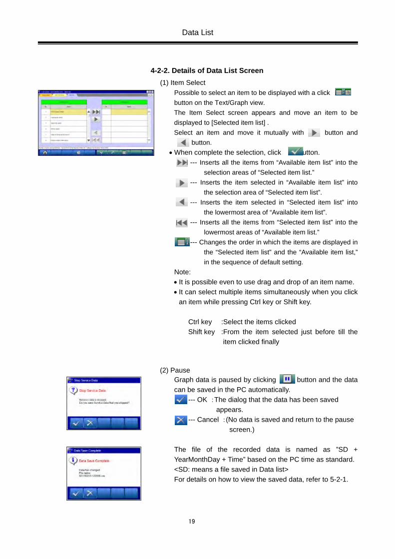
4-2-2. Details of Data List Screen (1) Item Select
Possible to select an item to be displayed with a click button on the Text/Graph view. The Item Select screen appears and move an item to be displayed to [Selected item list] . Select an item and move it mutually with button and
button. • When complete the selection, click button.
--- Inserts all the items from “Available item list” into the selection areas of “Selected item list.”
--- Inserts the item selected in “Available item list” into the selection area of “Selected item list”.
--- Inserts the item selected in “Selected item list” into the lowermost area of “Available item list”.
--- Inserts all the items from “Selected item list” into the lowermost areas of “Available item list.”
--- Changes the order in which the items are displayed in the “Selected item list” and the “Available item list,” in the sequence of default setting.
Note: • It is possible even to use drag and drop of an item name. • It can select multiple items simultaneously when you click
an item while pressing Ctrl key or Shift key. Ctrl key :Select the items clicked Shift key :From the item selected just before till the
item clicked finally
(2) Pause
Graph data is paused by clicking button and the data can be saved in the PC automatically.
--- OK :The dialog that the data has been saved appears. --- Cancel :(No data is saved and return to the pause
screen.) The file of the recorded data is named as ”SD + YearMonthDay + Time” based on the PC time as standard. <SD: means a file saved in Data list> For details on how to view the saved data, refer to 5-2-1.
Data List

20
(3) Data Range Change Click a data range field on the graph. When the selected field turned yellow, you can enter values. • Enter any values with the keyboard and press [Enter] key
or release the selection of the data range field to determine the change.
(4) All Items Record
By clicking button on displaying Data List (Text), all items can be saved into the laptop. The file name of the recorded data is set as ”AD + YearMonthDay + Time (military time including seconds)”, using the PC time as standard. It is saved in the folder named MUTDATA on the desktop Note: You can check the recorded data with a kind of general text editor software like Wordpad. (M.U.T.-III SE has no exclusive function to show it.) Click button. to 4-2-1.(1)
Data List

21
4-3. Actuator Test 4-3-1. Actuator Test
(1) Click Actuator Test on the screen 4-1-1.(2), the Actuator Test screen appears. Select an item to be tested from the pull-down menu.
-> When the selected item has no parameters -- to (2) -> When the selected item has parameters -- to (3)
--- Data List simultaneous display (Text) --- Data List simultaneous display (Graphs)
(2) Click button to execute Actuator Test. -- to (4) (3) The test item that you have selected needs to be set some
parameters. After completes the parameter setting, click button to execute the Actuator Test.
(4) Confirmation message appears. Click button.
Actuator Test
In case selected item has parameters

22
(5) Actuator Test Executing
If you want to interrupt the Actuator Test, click button. When completes the test, a dialog box appears. Click button. -> returns to screen (2) or (3).
• Data List simultaneous display (Text) Refer to (1)-(5).
-- Select items for Data list display -- to 4-2-2.(1)
• Data List simultaneous display (Graphs) Refer to (1)-(5).
-- Select items for Data list display -- to 4-2-2.(1)
-- Change Time Scale -- Change Data Scale
Note: • It can change the data range to any value.
(refer to 4-2-2.(3))
Actuator Test

23
4-4. All DTCs 4-4-1. Reading and Erasing All DTCs
(1) Click button after setting the vehicle to be diagnosed in the System Selection screen. * It cannot click button until all options are selected if
the system has.
(2) Select a button corresponding to your purpose.
Read all DTCs -- Displays a list of all DTCs read from vehicle ECU.
Erase and Read all DTCs -- Erases DTCs from system to system, and displays a list
of all DTCs read from vehicle ECU.
Note: • Diagnostic Trouble Code(s) that could not erase is(are) shown.
• Diagnostic Trouble Code(s) that takes much time to redetect after erasing is(are) not shown.
(3) System Selection
System List (*a) and Vehicle Information (*b) appears.
(i) Confirm the contents of the Vehicle Information (*b). -> When the contents are not describing the vehicle,
click button to correct it. (refer to 3-3-2)
(ii) Select the system on the System List (*a) and click
button. [System List (*a)] All the systems are selected in default. • Check the box with the systems to be read DTCs.
(Clear the mark with reselecting)
Note: • button---Set all systems selected on System list. • button---Set all systems unselected on System list.
• Deleting marks on systems which are not installed in the vehicle, will shorten the processing time.
• It is no problem even if a system which is not installed in the vehicle is selected.
All DTCs
*b *a

24
(4) Confirmation dialog box appears. Click button
(5) DTCs checking
The system that is being checked shows [Checking!] in red. The system that is being erasing shows [Erasing!]. (Only Erase and Read all DTCs selected)
(6) DTCs checking are complete.
Click button (7) Results
SSyysstteemm LLiisstt -Indicates presence or absence of DTCs on the results field as below.
“OK” : DTCs are not detected “TC” : DTCs are detected “NC” : Not equipped or communication error “-” : Unchecked (out of the check system)
DDiiaaggnnoossttiicc ttrroouubbllee ccooddee((ss)) -All detected DTCs are listed. -Indicates status of the DTCs as below. “Active” : The trouble occurs currently “Stored” : The trouble had occurred in past “ - ” : Not supporting status recognition
When selecting a system with “TC” result on the SSyysstteemm LLiisstt, columns of corresponding DTC on the DDiiaaggnnoossttiicc ttrroouubbllee ccooddee((ss)) will appear in blue color. Clicking button returns the screen to (2).
All DTCs

25
Chapter 5 Drive Recorder 5-1. How to Record the Data
5-1-1. Recording (1) Select a system for which the drive recorder is to be
used on the System Selection screen. (For instruction on how to select a system, refer to
3-3-1(2)) - The following explanation describes how to set the drive
recorder settings of the MPI/GDI/DIESEL system as a representative example. Click button after selecting vehicle information and MPI/GDI/Diesel.
(2) Selection of function. Click Drive Recorder button.
(3) Drive Recorder Function Select Click Record button on the Drive Recorder function menu. Note:
Data display -- Displays the recorded data. (refer to 5-3)
How to Record the Data
26
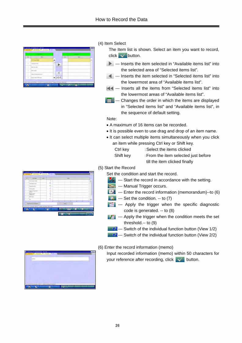
(4) Item Select The Item list is shown. Select an item you want to record, click button.
--- Inserts the item selected in “Available items list” into the selected area of “Selected items list”.
--- Inserts the item selected in “Selected items list” into the lowermost area of “Available items list”.
--- Inserts all the items from “Selected items list” into the lowermost areas of “Available items list”.
--- Changes the order in which the items are displayed in “Selected items list” and “Available items list”, in the sequence of default setting.
Note: • A maximum of 16 items can be recorded. • It is possible even to use drag and drop of an item name. • It can select multiple items simultaneously when you click
an item while pressing Ctrl key or Shift key. Ctrl key :Select the items clicked Shift key :From the item selected just before
till the item clicked finally (5) Start the Record
Set the condition and start the record. --- Start the record in accordance with the setting. --- Manual Trigger occurs. --- Enter the record information (memorandum)--to (6) --- Set the condition. -- to (7) --- Apply the trigger when the specific diagnostic
code is generated. -- to (8) --- Apply the trigger when the condition meets the set
threshold.-- to (9) --- Switch of the individual function button (View 1/2) --- Switch of the individual function button (View 2/2)
(6) Enter the record information (memo)
Input recorded information (memo) within 50 characters for your reference after recording, click button.
How to Record the Data

27
(7) Set the Record condition • The sampling interval time indicates the data-recording
interval for one item. Possible to select one of the intervals in 0sec(Fastest)/0.5sec/1sec/10sec.
• Possible to set the number of point to be able to record after the trigger occurred. (The actual interval in the case of 0sec(Fastest) is approximately 20msec in CAN communication although it varies according to conditions such as the processing of record items. The amount of data available is up to 100,000 points, then possible to record for approximately 30min. (about 20msec x 100,000) under the condition of the fastest interval.
(8) Diagnosis Code Trigger - Item Select
When click button in (5) Start the Record screen, the left screen appears. Select an item to be the trigger and click button.
(9) Set the Threshold Trigger
• When click button in (5) Start the Record screen, the left screen appears.
• Select an item and edit conditions in Condition Editing table appearing at the bottom of the screen, first.
Condition Editing table “UP/DOWN”: Threshold or higher / Threshold or lower “Level/Edge”: Matching data / Data as of the time when it turns
to be matching from not matching “AND/OR”:-Data matching with both of this condition and the
other one upper row on Condition of Trigger table / -Data matching with either of this condition or the other one upper row on Condition of Trigger table
• Then, click button to set the condition into selected
area of Condition of Trigger table. (Condition of Trigger table can include up to 8 conditions.)
• When completed the setting, click button.
How to Record the Data

28
(10) Recording Data Screen • Click button in (5), it saves the items with the record
condition in the file, showing maximum 8 items at the same time on the graph. Even the items that are not displayed are recorded as well.
--- Data record end -- to (11) --- Manual Trigger occurs
Note: • Record is continued until button is clicked, even if
trigger occurs. • A red solid line on the graph shows a trigger point. • The actual measurement of the sampling interval is
shown to the screen lower left. • The availability of the hard disk of the PC is checked after
record screen display and before record start. When the availability is 100MB or less, a message is displayed and record is stopped.
• When the number of point after the trigger would reach to ones set in (7), the message appears and end the record.
• When an error occurs during data recording, the data has being recorded till then is saved if there might.
(11) Save record data Click button in (10), end the recording, save the data and a dialog mentioned completion of saving for the record data is shown.
--- OK-- to Drive Recorder Function Select menu (refer to (3)).
Note:
In case there is no record data, a dialog is displayed confirming whether to stop the recording.
-- OK-- to Drive Recorder Function Select menu (3) -- Cancel -- to (10) to start recording again
(12) When you check the recorded data, continue to 5-2-1.
How to Record the Data

29
5-1-2. Reuse past setting condition (1) Record (Read Setting Conditions) button allows you to
restore past recording conditions so that you can execute recording under the same conditions as those used with previously recorded data files.
(2) Select the data you want to restore from the Setting Conditions list. After selecting the setting condition, possible to re-set condition.
--- OK -- to 5-1-1.(5) --- Return to (1)
How to Record the Data

30
5-2. Recorded Data Handling 5-2-1. Display the recorded data
(1) Click Data display in the menu screen of the recorded system to display the data after recording. To display the data without vehicle connection, then click
button first and click from Drive Recorder to Data display in order in the System Select screen. Note: ・In case of displaying data recorded in other PC, the data
must be saved in fixed directory below in advance. C:¥MUTSW_SE¥MUT3_SE¥Temp¥RecData¥
(2) Recorded data file list
• Data file list that contains record of Drive recorder and Data list saved in PC will be displayed.
• The background color of the line containing the selected file changes into yellow.
-- Displaying Graph data (refer to 5-2-1.(3)) -- Displaying Text data (refer to 5-2-1.(3)) -- Edit record information (refer to 5-2-1.(4)) -- Delete the data file (refer to 5-2-2.(1)) -- Save the data file (refer to 5-2-2.(2))
Note: • The file name of the recorded data is set as
”DR(SD) + YearMonthDay + Time (military time including seconds)”, using the PC time as standard.
• The most recent recorded data appears on top of the list.
• <DR: The file saved by the drive recorder is meant> • <SD: The file saved by the data list is meant>
(3) Display the recorded data
Displaying Text Data
--- Displaying Graph data --- Select item (refer to 5-2-1.(5)) --- Time extraction (refer to 5-3-1.(1)) --- Save data (refer to 5-3-1.(2)) --- Switch of the individual function button (View 1/2) --- Switch of the individual function button (View 2/2)
Recorded Data Handling

31
Displaying Graph Data
--- Displaying Text data --- Select item (refer to 5-2-1.(5)) --- Time extraction (refer to 5-3-1.(1)) --- Enlarge Time range --- Reduce Time range --- Save data (refer to 5-3-1.(2)) --- Switch of the individual function button (View 1/2) --- Switch of the individual function button (View 2/2)
Note: • A red solid line on the graph shows a trigger point. • It can change the data range to any value
(refer to 4-2-2.(3))
(4) Edit Data Information Select a file to edit and click button to display the screen illustrated on the left, where you can edit the record information that was entered in 5-1-1(6). When click button, the confirmation dialog appears, then click button.
(5) Select item Possible to select item you want to display in Text/Graph. Refer to 4-2-2.(1) for details.
Recorded Data Handling

32
5-2-2. Deleting/Saving recorded data (1) Delete Data
To delete a data file loaded on the PC, click the check box next to file No. in the file list (refer to (3)) to place a check mark, and click button. (Two or more check marks can be placed.) When click Delete button, the confirmation dialog appears, then follow the messages. Note: mark will be displayed, if cursor is moved on a check box and it clicks. (Selection) mark is eliminated by clicking again. (Selection release)
(2) Save Data (i) The data file can be saved to a removable media (USB
memory or SD memory card). -Insert a removable media into the PC, first. -Click the check box next to the file No. in the file list to place a check mark, and click button.
(Two or more file selections are possible.) Note: mark will be displayed, if cursor is moved on a check box and it clicks. (Selection) mark is eliminated by clicking again. (Selection release)
(ii) Drive Select
Select a drive for saving the data files, and click button.
Recorded Data Handling

33
5-3. Analysis of the Recorded Data 5-3-1. Extraction of the recorded data
(1) Set Time extraction condition Possible to extract the recorded data in time range.
Set time range to be extracted on this screen, then only extracted data is shown after clicking button.
(2) Data Save Click button on the screen in Text/Graph to save the extracted data in the PC. The file name consists of original data file name + alphabet (a,b..z).
Analysis of the Recorded Data

34
Chapter 6 CAN Bus Diagnosis 6-1. Diagnosing the CAN Bus < CAUTION > • When you execute CAN Bus diagnosis, halt the vehicle.
6-1-1. CAN Bus Diagnosis
(1) Click button after setting the vehicle information on the right of System Select screen.
(2) Equipping System Setup Put a check mark if the equipment is existence, and click
button. Note: ・ mark will be displayed, if cursor is moved on a
check box and it clicks. (Selection) ・ mark is eliminated by clicking again. (Selection
release)
(3) CAN Bus Diagnosis Clicking button starts the CAN bus diagnosis process.
Note: The right lower message box shows the details of ECU names displaying on the configuration screen.
(4) Results
The results of the diagnosis are reflected on the configuration screen (Error locations are indicated in red), and the comment is shown on the center lower message box.
--- This button is able to zoom out the CAN Bus configuration screen. When a button is clicked again, the CAN Bus configuration screen returns to the original size.
Diagnosing the CAN Bus

35
Chapter 7 Computer Diagnosis 7-1. Operation method of MiEV Computer Diagnosis
7-1-1. Setting and execution of MiEV Computer Diagnosis
(1) You can perform the MiEV computer diagnosis.
Click button after setting the vehicle information on the right of System Select screen.
(2) Click MiEV Computer Diagnosis button on the Special function Menu.
(3) Click Diagnosis button on the MiEV Computer Diagnosis Menu. Note: Save File Management -- The saved file at diagnostic result is having a look displayed. (refer to 7-1-2) < Remark > There is a possibility that correct diagnostic result is not expected to obtain in the state of less than 50% charge of the high voltage battery, so please ensure that it is fully charged for your operation.
Operation method of MiEV Computer Diagnosis

36
(4) Input of the customer's name Please input of customer’s name. 32 characters are allowed to input.
-- OK -- to (5)
(5) Input of the vehicle identification number Please input VIN of the vehicle to be diagnosed. 17 characters are allowed to input.
-- OK -- to (6)
(6) CAN Bus Diagnosis CAN bus diagnosis is executed by clicking the button after setting the equipped system.
(7) DTC Check The DTC Check is executed by clicking the button after setting of the system and the option select.
(8) High-Voltage Battery Check In the power switch of the vehicle is in the status of “READY", the high voltage battery check is executed automatically.
Operation method of MiEV Computer Diagnosis

37
(9) ELC.water heater test ELC.water heater test is executed automatically.
(10) Diagnosis completed When all diagnoses are completed, the dialog that MiEV computer diagnosis was completed is displayed.
-- OK -- to (11)
Operation method of MiEV Computer Diagnosis

38
(11) Print preview The print preview of the diagnostic result is displayed, you can print it out if needed.
Print preview of MiEV computer diagnosis report
Operation method of MiEV Computer Diagnosis

39
7-1-2. Save File Management
(1) Diagnosis result data list
Click Save File Management button on the MiEV Computer Diagnosis Menu at 7-1-1(3), the data saved with MiEV Computer Diagnosis is displayed. Five functions that display / print of diagnostic result, correction of information on data, delete of data, saving data to removable disk and storing data to PC are available.
-- Print of diagnostic result -- to (2) -- Edit record information -- to (3) -- Delete the data file -- to (4) -- Save the data file -- to (5) -- Storing the data file -- to (6)
< Remark > It is sequentially displayed from the latest data in the upper part of the table. The background color of the selected file turns yellow. Save / Delete button of data cannot be clicked until the check box in the left part in the table is checked.
(2) Print of the diagnosis result The diagnostic result of the data selected in the diagnosis result data table of (1) is displayed on the print preview screen. Please print after connecting the printer.
(3) Edit Data Information Information on the saved data selected in the table of (1) can be edited again. (information input by (4) - (5) of 7-1-1.)
-- To (1) after saved edit information. -- To (1) after deleted edit information.
Operation method of MiEV Computer Diagnosis

40
(4) Delete Data Data that checks( ) Save / Del column is deleted in the diagnosis result data table of (1).
(5) Save Data Data that checks( ) Save / Del column in the diagnosis result data table of (1) is kept on a removable disk. Please select the drive that preservation data from the drive table.
-- To (1) after saved data in the selected drive. -- To (1) after it cancels.
(6) Data Storing
Please select the removable disk that a diagnosis result data is kept on from Drive List.
-- To (1) after stored data from the selected drive. -- To (1) after it cancels.
Operation method of MiEV Computer Diagnosis
41
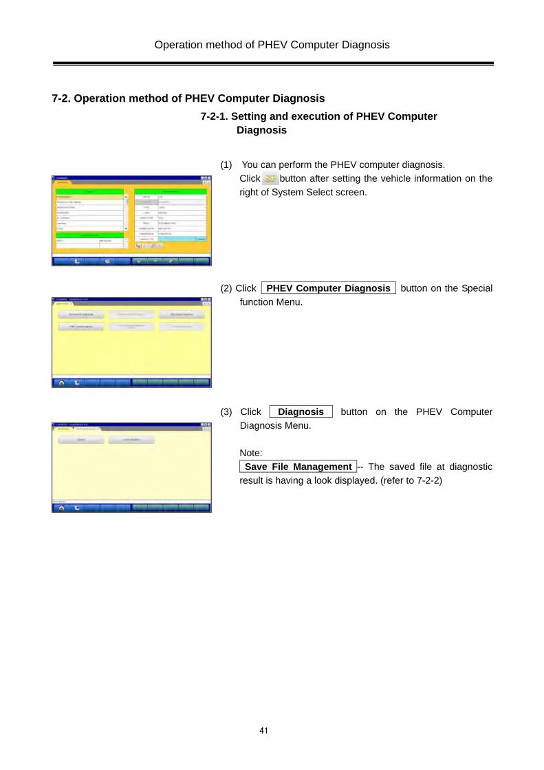
7-2. Operation method of PHEV Computer Diagnosis 7-2-1. Setting and execution of PHEV Computer
Diagnosis
(1) You can perform the PHEV computer diagnosis.
Click button after setting the vehicle information on the right of System Select screen.
(2) Click PHEV Computer Diagnosis button on the Special function Menu.
(3) Click Diagnosis button on the PHEV Computer Diagnosis Menu. Note: Save File Management -- The saved file at diagnostic result is having a look displayed. (refer to 7-2-2)
Operation method of PHEV Computer Diagnosis

42
(4) Input of the customer's name Please input of customer’s name. 32 characters are allowed to input.
-- OK -- to (5)
(5) CAN Bus Diagnosis CAN bus diagnosis is executed by clicking the button after setting the equipped system.
(6) DTC Check The DTC Check is executed by clicking the button after setting of the system and the option select.
(7) Diagnosis completed When all diagnoses are completed, the dialog that PHEV computer diagnosis was completed is displayed.
-- OK -- to (8)
Operation method of PHEV Computer Diagnosis

43
(8) Print preview The print preview of the diagnostic result is displayed, you can print it out if needed.
Print preview of PHEV computer diagnosis report
Operation method of PHEV Computer Diagnosis

44
7-2-2. Save File Management
(1) Diagnosis result data list
Click Save File Management button on the PHEV Computer Diagnosis Menu at 7-2-1(3), the data saved with PHEV Computer Diagnosis is displayed.
-- Print of diagnostic result -- to (2) < Remark > It is sequentially displayed from the latest data in the upper part of the table. The background color of the selected file turns yellow.
(2) Print of the diagnosis result The diagnostic result of the data selected in the diagnosis result data table of (1) is displayed on the print preview screen. Please print after connecting the printer.
Operation method of PHEV Computer Diagnosis
45
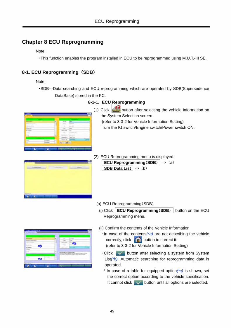
Chapter 8 ECU Reprogramming Note:
・This function enables the program installed in ECU to be reprogrammed using M.U.T.-III SE.
8-1. ECU Reprogramming(SDB)
Note:
・SDB---Data searching and ECU reprogramming which are operated by SDB(Supersedence
DataBase) stored in the PC. 8-1-1. ECU Reprogramming
(1) Click button after selecting the vehicle information on the System Selection screen. (refer to 3-3-2 for Vehicle Information Setting) Turn the IG switch/Engine switch/Power switch ON.
(2) ECU Reprogramming menu is displayed. ECU Reprogramming(SDB) -> (a) SDB Data List -> (b)
(a) ECU Reprogramming(SDB) (i) Click ECU Reprogramming(SDB) button on the ECU
Reprogramming menu. (ii) Confirm the contents of the Vehicle Information ・In case of the contents(*a) are not describing the vehicle
correctly, click button to correct it. (refer to 3-3-2 for Vehicle Information Setting)
・Click button after selecting a system from System List(*b). Automatic searching for reprogramming data is operated. * In case of a table for equipped option(*c) is shown, set
the correct option according to the vehicle specification. It cannot click button until all options are selected.
ECU Reprogramming
*a
*b
*c

46
(iii) Reprogramming data is listed.
The appropriate reprogramming data is indicated.
Place mark to the check box with the reprogrammed
systems and press button to go to next. Note: ・ mark will be displayed, if cursor is moved on a
check box and it clicks. (Selection) ・ mark is eliminated by clicking again. (Selection
release) ・The following dialog may appear depending on the
state of the ECU. In those cases, ECU reprogramming is not needed.
Reprogramming is not necessary.
Nothing is displayed in the list.
Reprogrammed already. "Completed" is displayed in the Search result area.
(iv) Check reprogramming data
・Reprogramming is executed by clicking button. -> (v)
・Click button in order to re-select the data. -> (iii)
ECU Reprogramming

47
(v) Reprogramming Reprogramming on board ECU starts.
(vi) Reprogramming completed Confirmation dialog box appears. Click button.
(vii) Results Reprogramming result is displayed. Click button. -> (2)
(b) SDB Data List
Click SDB Data List button on the ECU Reprogramming menu. Reprogramming data files in the hard disk are listed.
Note:
Reprogramming cannot be executed by selecting from
SDB Data List.
ECU Reprogramming

48
8-2. Trouble of Reprogramming No. Message Cause Remedy
1
・Lack of a power supplied to V.C.I.-Lite due to a problem on a vehicle such as low battery.
・Connection between V.C.I.-Lite and vehicle malfunctioned.
・Connection between PC and V.C.I.-Lite malfunctioned.
・Check the battery voltage. ・Confirm connection between V.C.I.-Lite and vehicle.
・Confirm connection between PC and V.C.I.-Lite.
2
・While reprogramming, an error occurred. ・IG switch/Engine switch/Power switch positioned “OFF”.
・Wrong setting of selected vehicle/ system/equipped option.
・The ECU is broken.
・Restart reprogramming process over again. ・Turn the IG switch/Engine switch/Power switch ON.
・Check setting of selected vehicle/system/ equipped option.
・Troubleshoot by following the instructions of the workshop manual.
3
・No reprogramming data (MFF file) exists in PC. ・Reinstall reprogramming data.
4
・While reprogramming, an error occurred. ・Restart reprogramming process over again.
ECU Reprogramming

49
Chapter 9 How to Use (Special Case) 9-1. Copy Coding
The procedure “Copy Coding” is described below. 1) Read and save the coding data which is stored in the old ECU.
-> 9-3-1 – 9-3-2 2) Read and save the customization data which is stored in the old ECU.
(ETACS ECU Only) -> 9-4-1 – 9-4-2
3) Exchange the ECU. 4) Write the chassis No. or VIN to installed ECU.
(In case of the installed ECU has never been written the chassis No. or VIN, this procedure is not needed since them will be written automatically. (Except engine ECU))
-> 9-2-1 (Engine ECU in the vehicle with immobilizer and without OSS stand-alone
ECU)
-> 9-2-2 (other) 5) Write the saved coding data in procedure 1 to installed ECU.
-> 9-3-3 6) Write the saved customization data in procedure 2 to installed ECU.
-> 9-4-3
Copy Coding

50
9-2. Chassis No. / VIN Writing and Chassis No. / VIN Information 9-2-1. Chassis No. / VIN Writing
(Case of engine ECU in the vehicle with immobilizer and without OSS stand-alone ECU)
(1) As a typical example, procedure for Chassis No. or VIN writing in KOS/IMMO/Keyless is explained below. Other system may have different menu structure but procedure is basically the same.
Note: Click button after setting the vehicle information on the right of the screen and select Immobilizer system on the left of the screen. (refer to 3-3-1.(2) for System Selection)
(2) Click Special Function button. (3) Special function menu is displayed. ENG key code & Chassis No/VIN Reg – Registration of
engine key code and chassis No. or VIN writing. --> (4)
ENG key code Reg. – Registration of engine key code only. Use only if correct chassis No. or VIN has been written to the ECU.
--> (4) (4) The key code is registered to engine ECU.
Click button.
Chassis No. / VIN Writing and Chassis No. / VIN Information

51
(5) Click button. In case of ENG key code Reg. was selected, return to (3).
(6) Click button after inputting chassis No. or VIN. (7) Confirmation dialog box is appears. Click button. (8) Completion dialog box is appears.
Click button. (9) Written chassis No. or VIN is displayed.
Check if chassis No. or VIN was written correctly. Click button. --> returns to screen (3).
Chassis No. / VIN Writing and Chassis No. / VIN Information

52
9-2-2. Procedure of Chassis No. / VIN Writing (Other case)
(1) Select a system on the System Selection screen in which you want to write Chassis No. or VIN. (For instruction on how to select a system, refer to 3-3-1(2).)
Note:
As a typical example, procedure for Chassis No. or VIN writing in MPI/GDI/Diesel is explained below. Other system may have different menu structure but procedure is basically the same. Select the vehicle information on the right of the screen and a “MPI/GDI/Diesel” to be checked on the left, then click button.(refer to 3-3-1(2).)
(2) Click Coding button. (3) Coding menu is displayed. Chassis No./VIN Writing – Chassis No. or VIN is written. -> (4) Chassis No./VIN Information – Chassis No. or VIN is
displayed. -> 9-2-3 (4) Select whether immobilizer and/or OSS are equipped in the
vehicle and click button. (without OSS stand-alone ECU)
*This screen cannot be displayed depending on the selected vehicle and system. In this case, proceed to (5)
Chassis No. / VIN Writing and Chassis No. / VIN Information

53
(5) Input chassis No. or VIN and click button. (6) Confirmation dialog box appears. Click button. (7) Completion dialog box is appears.
Click button. (8) Written chassis No. or VIN is displayed. Check if chassis No.
or VIN was written correctly. Click button. --> returns to screen (3).
9-2-3. Chassis No. Information or VIN Information Current chassis No. or VIN is displayed.
Chassis No. / VIN Writing and Chassis No. / VIN Information

54
9-3. Coding Operation 9-3-1. Confirmation of The Current ECU Coding Data
(1) Select a system on the System Selection screen in which you want to perform Coding. (For instruction on how to select a system, refer to 3-3-1(2).)
Note:
As a typical example, procedure for Coding in MPI/GDI/Diesel is explained below. Other system may have different menu structure but procedure is basically the same. Select the vehicle information on the right of the screen and a “MPI/GDI/Diesel” to be checked on the left, then click button.(refer to 3-3-1(2).)
(2) Click Coding button. (3) Coding menu is displayed.
On Vehicle Coding -- Writing a coding data --> to 9-3-3
Coding Information & Copy -- Reading and saving the current ECU coding data.
--> to (4)
(4) The current ECU coding data is displayed. -- Save Data --> refer to 9-3-2
Coding Operation

55
9-3-2. Save of The ECU Coding Data (1) Click button on the screen 9-3-1(4), and the left
screen will be displayed. Click button. Note: If diagnostic trouble codes are currently stored in the ECU, the file cannot save. Retry after the vehicle is repaired.
(2) Confirm the displayed name of the saved file. Click button. Note: The name of the saved file is set as
”ECU parts No., Chassis No. or VIN, Date and No.”
9-3-3. Procedure of Variant Coding Writing (1) Save a coding data into the fixed directory (*1) by
-To read the coding data out of the ECU
(refer to 9-3-2) or
-To obtain a variant coding file in advance *1: the fixed directory “C:¥MUTSW_SE¥MUT3_SE¥CdgData¥”
(2) Input a chassis No. or a VIN to list up applied coding files
and click button. Note: If coding file is not found in the folder, left screen may appear. In such case, click button. Save the correct file in the folder and try again.
Coding Operation

56
(3) The applied coding files by the inputted are displayed. Choose a coding file to be written and click button. -The background color of the line containing the selected file changes into yellow. -- select a directory -- delete the files --> to 9-3-4
(4) The current ECU coding data and the coding data to be written are displayed. Click button if OK.
(5) Confirmation dialog box appears.
Click button Note:
-In case of ETACS, “ETACS customize” and “Option Coding” are initialized after writing variant coding. Rewrite them after finishing coding. -It is not need that “Option Coding” is executed because the data of “Option coding” includes in variant coding data, if “Copy Coding” was executed.
(6) Completion dialog box is appears.
Click button
(7) Written coding data is displayed. Check if the coding data was written correctly. Click button. --> returns to screen 9-3-1(3)
Coding Operation

57
9-3-4. Delete of Coding Files To delete a data file loaded on the PC, click the check box next to file No. in the file list (refer to 9-3-3(3)) to place a check mark, and click button.
(Two or more check marks can be placed.) Note: mark will be displayed, if cursor is moved on a check box
and it clicks. (Selection) mark is eliminated by clicking again. (Selection release)
Coding Operation

58
9-4. Customization Operation 9-4-1. Confirmation of The Current Customization Data
(1) Select “ETACS” on the System Selection screen. (Select the vehicle information on the right of the screen and a “ETACS” to be checked on the left, then click button.(refer to 3-3-1(2).)
(2) Click Special Function button. (3) Special function menu is displayed.
Customization -- Writing a customization data --> to 9-4-3
Customization Information -- Reading the current customization data and saving the data to file
--> to (4)
(4) The current customization data is displayed. -- Save Data --> refer to 9-4-2
Customization Operation

59
9-4-2. Save of The Customization Data (1) Click button on the screen 9-4-1(4), and the left screen
will be displayed. Click button.
(2) Confirm the displayed name of the saved file. Click button. Note: The file name of the saved file is set as
”ECU parts No., Chassis No. or VIN, Date and No.”
9-4-3. Procedure of Customization (1) The current customization data and the customization data
to be written are displayed. Load the customization data file or change the value. Then
click button. -- load customization data --> to 9-4-4
(2) Confirmation dialog box appears. Click button
(3) Completion dialog box is appears. Click button
(4) Written customization data is displayed. Check if the customization data was written correctly. Click button. --> returns to screen 9-4-1(3)
Customization Operation

60
9-4-4. Load the Customization Data The applied customization files by the inputted are displayed.
Choose a customization file to be written and click button. -The background color of the line containing the selected file changes into yellow. -- select a directory -- delete the files --> to 9-4-5
9-4-5. Delete of Customization Files To delete a data file loaded on the PC, click the check box next to file No. in the file list (refer to 9-4-4) to place a check mark, and click button.
(Two or more check marks can be placed.) Note: mark will be displayed, if cursor is moved on a check box and it clicks. (Selection) mark is eliminated by clicking again. (Selection release)
Customization Operation

61
Chapter 10 Reference Material 10-1. V.C.I.-Lite Electrical Properties
<Power Supply Properties>
Rated voltage DC12V, 24V
Ground polarity (-)
Power supply (guaranteed operation range) DC 8.0 - 32.0 V
Power supply reverse current DC - 40 V (1 minute period)
Unit current consumption (maximum) 350mA
(When voltage is within the guaranteed operation range) • Excludes conditions when the voltage is not within the guaranteed operation range and special
conditions such as when a ground short occurs on an updated control terminal, etc. The amount of current consumption when the unit is used with rated power supply is 200mA or less.
V.C.I.-Lite Electrical Properties

62
Appendix << Copyright belonging >> • Adobe, the Adobe logo, and Reader are either registered trademarks or trademarks of Adobe
Systems Incorporated in the United States and/or other countries.
<<Copyright belonging>>