multi-variable analog interface for smart transmitters ...eneric.net/honeywell/technical-data/mva...
TRANSCRIPT

Multi-Variable Analog Interface for Smart Transmitters Specifications 34-MV-03-01 December 1999
Description
The Multi-Variable Analog (MVA) interface is an ideal
choice for interfacing Honeywell’s Digitally Enhanced (DE)
Smartline™ transmitters with analog input controllers,
safety shutdown systems, and recorders while utilizing the
advantages of digital communications.
The MVA is fully compatible with all Honeywell Smartline™
transmitters, single and multivariable. This includes the
SMV 3000 Smart Multivariable Transmitter, ST 3000 Smart
Pressure Transmitters, SGC 3000 Smart Gas
Chromatograph STT 3000 Smart Temperature Transmitter
and MagneW 3000 Smart Flowmeter.
The MVA is also compatible with all Honeywell DE control
system interfaces (STDC, STI MV). Communicators, like
Honeywell’s SFC and SCT, may be used with no
disturbances to the module’s analog output or status.
Safety System Advantages
By integrating a transmitter’s diagnostic status into the
shutdown strategy, the MVA enables a solution with less
transmitters by providing positive a means of differentiating
a maintenance problem from a process problem while
helping avoid process upsets and false shutdowns. By fully
supporting forced I/O manual (e.g. Output Mode), the MVA
enables validation testing of safety shutdown system with
handheld devices.
Benefits
Mix DE and Analog instrumentation.
Enables stand-alone digital operation.
Enables lower cost solution in dual or triplicated safety
systems.
Leverage wiring savings associated with multivariable
transmitters.
Use Honeywell multivariable transmitters with any
analog system.
Economically extracts PVs and SVs.
Enables full digital, non-bumping communications for
any application.
How it Works
MVA works by converting a single transmitter’s digital PV
into 1-5 volt analog signal(s). In addition, it monitors the
transmitter diagnostic status and causes the module’s
analog output to go fail-safe low in case of bad status.
Digital Control Integrationwith Analog Instrumentation . . .
Analog
Recorder
Backup orCritical Loop
SLC
SFC/SCT
Digital PV, Status & Database
“smart” status
SmartMultivariable
ControlSystem
SafetySystem
MaintenanceShop
MVAMVA
DE
Transmitter
Error! Not a valid link.
HFS Catalog_Without Tab_HighRes.pdf 1530 6/8/2011 12:42:09 PM

Multi-Variable Analog Interface for Smart Transmitters 2
Features
Up to 4 analog outputs.
Use with single or multivariable transmitters.
Transmitter diagnostic status incorporated into analog
output.
Independent transmitter status relay output.
“Output Mode” pass-through.
“Smart status” LED indicators.
Modular DIN rail mount.
Test mode.
Specifications:
# Input Channels: 1
Input Type: Honeywell DE, 4 or 6 byte, multivariable
Analog Output(s): up to 4 @ 1-5 volts, nom. 10% over/under-range, min.
Analog Output Accuracy: 0.045% F.S., into 10 Kohms load, min.
Analog Output Throughput Delay:
50 msec., max. to 99% of new PV/SV value
PV/SV Selection: PV1, PV2, PV3, PV4 or SV1
Status Relay: 1 Form A and 1 Form B, 5A @ 30VDC, 250VAC, 0.1HP
“Smart Status”: Transmitter status, forced I/O manual mode, DE signal integrity, MVA test mode and MVA fault.
LED Indicators (4): POWER, RELAY, DE, STATUS
Field Communicator Interaction: No change to PV/SV value or Status state.
Power Supply: +18VDC to +30VDC, +24VDC nom. @ 80mA., typ. (excludes transmitter)
Connectors: Screw type, compression, removable, keyed
Module Size: 4.51”(H) x 0.89”(W) x 3.9”(D)
Operating Temperature: 0°C to +60°C, ambient
Enclosure/Mounting: IP 20 / 35 mm DIN Rail (EN 50022) mounted equipment
CE Conformity (Europe) This product is in conformity with the protection requirements of the following European Council Directives: 73/23/EEC, the Low Voltage Directive, and 89/336/EEC, the EMC Directive. Conformity of this product with any other “CE Mark” Directive(s) shall not be assumed.
Product Classification: Class I: Fixed, Permanently Connected, Equipment. (EN 61010-1)
Installation Category (Overvoltage Category):
Category II: Energy-consuming equipment supplied from the fixed installation. Local level appliances and Industrial Control Equipment. (EN 61010-1)
Pollution Degree: Pollution Degree 2: Normally non-conductive pollution with occasional conductivity caused by condensation. (ref. IEC 664-1)
EMC Classification: Group 1, Class A, Industrial Control Equipment (EN 55011, emissions)
Generic Immunity, Industrial (EN 50082-2, immunity)
CSA Certification (Canada) CSA C22.2 No. 205M – Signal Equipment
UL Standard (USA) CSA NRTL/C, UL 1635 – Digital Alarm Communicator System Unit
HFS Catalog_Without Tab_HighRes.pdf 1531 6/8/2011 12:42:09 PM

Multi-Variable Analog Interface for Smart Transmitters 3
For More Information
Learn more about how Honeywell’s Multi-Variable Analog
Interface for Smart Transmitters can provide stand-alone
digital operation, visit our website
www.honeywell.com/ps/hfs or contact your Honeywell
account manager.
Honeywell Process Solutions
1860 West Rose Garden Lane
Phoenix, Arizona 85027
Tel: 1-800-423-9883 or 1-800-343-0228 www.honeywell.com/ps
34-MV-03-01December 1999 © 2010 Honeywell International Inc.
HFS Catalog_Without Tab_HighRes.pdf 1532 6/8/2011 12:42:09 PM

Multivariable Trip Switch for Smart Transmitters Specifications 34-MV-03-02 December 1999
Trip Switch Application with Maintenance Indication,Trip Switch Application with Maintenance Indication,Analog Repeat and Digital Integration . . .Analog Repeat and Digital Integration . . .
SFC
Bumpless DE Communications
Trip
SmartTransmitter
Status
TDC ControlSystem(optional)
MaintenanceShop
Analog (optional)
MTSMTS
Recorder
ShutdownControls
digital PV, status& database
Trip
Analog
Status
DE
DE
Description
The Multivariable Trip Switch (MTS) supplies a stand
alone safety shutdown solution that can range from simple
shut-off of a pump or motor to part of a larger system
solution. MTS works with Honeywell SmartlineTM field
instruments or with any analog instrument to provide a
configurable high or low trip. A second relay and one
analog repeat output are optionally available.
The MTS is compatible with all Honeywell Smartline
transmitters, including the SMV 3000 Smart Multivariable
Transmitters, ST 3000 Smart Pressure Transmitters, SCM
3000 Smart Coriolis Mass Flowmeters, STT 3000 Smart
Temperature Transmitters, the SGC 3000 Smart Gas
Chromatograph, and MagneW 3000 and MagneW 3000
PLUS Smart Flowmeters. In addition, MTS works with any
of Honeywell's DE control system interfaces (STDC, STI-
MV). Honeywell's hand-held communicator, the SFC
Smart Field Communicator, and the PC-based SCT 3000
Smart Configuration Toolkit may be used with no
disturbances to the analog repeat output or status.
The MTS may be installed without disconnecting or
disrupting the existing installation and may be used stand-
alone or as an addition to an integrated control solution.
Benefits Zero-error digital PV trip.
Eliminates false process shutdowns by isolating xmtr
status from PV trip.
One model with DE or ANALOG 4-20ma. input
capability.
Leverages wiring savings associated with multivariable
transmitters via individual trips on any PV.
Enables full digital, non-bumping communications for
any application
Leverages wiring savings associated with multivariable
transmitters via individual trips on any PV.
Expands functionality while maintaining full digital
integration.
NO calibration or special configuration tools are
required
Figure 1
Safety System Advantages
The MTS provides a cost effective zero-error digital
shutdown solution. The independent “smart status” output
enhances the speed safety shutdown systems are able to
respond by tracking the transmitter’s status. “Smart status”
also eliminates the need for separate Hi/Hi and Lo/Lo trips.
The MTS fully supports forced I/O manual mode for
validation testing of safety shutdown system. Multiple MTSs
may be used with the same transmitter.
How it works
MTS monitors a single transmitter’s digital PV/SV or analog
4-20ma. signal and compares its value with the configured
trip point. With a DE signal, MTS also provides an
independent “smart status” derived from the digital
transmitter’s status and MTS module status. The “smart
status” may be OR’ed with the PV/SV trip state.
The compact module design is suitable for DIN rail mounting
and is intended to be mounted within an appropriate
enclosure. MTS operates from a single +24VDC source and
is internally short-circuit protected..
HFS Catalog_Without Tab_HighRes.pdf 1533 6/8/2011 12:42:09 PM
Multivariable Trip Switch for Smart Transmitters 2
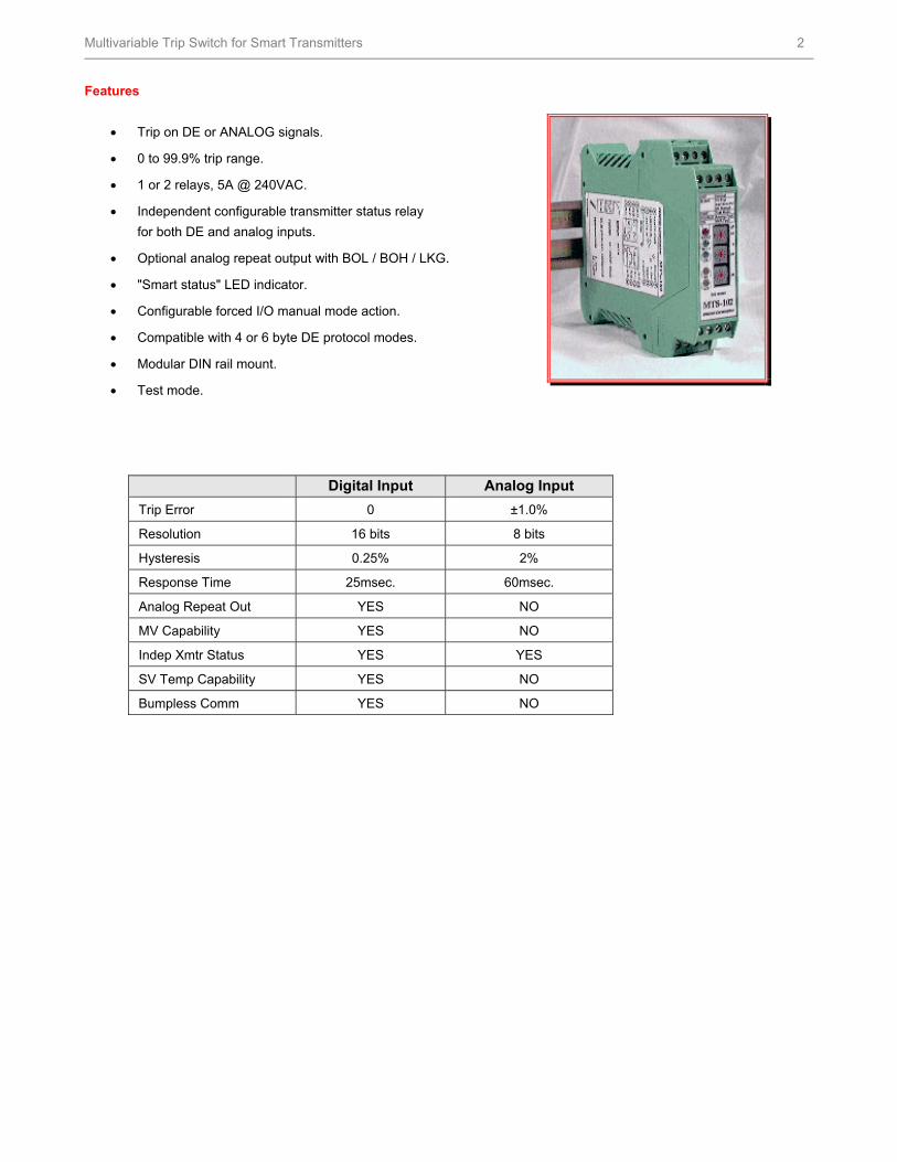
Features
Trip on DE or ANALOG signals.
0 to 99.9% trip range.
1 or 2 relays, 5A @ 240VAC.
Independent configurable transmitter status relay
for both DE and analog inputs.
Optional analog repeat output with BOL / BOH / LKG.
"Smart status" LED indicator.
Configurable forced I/O manual mode action.
Compatible with 4 or 6 byte DE protocol modes.
Modular DIN rail mount.
Test mode.
Digital Input Analog Input
Trip Error 0 ±1.0%
Resolution 16 bits 8 bits
Hysteresis 0.25% 2%
Response Time 25msec. 60msec.
Analog Repeat Out YES NO
MV Capability YES NO
Indep Xmtr Status YES YES
SV Temp Capability YES NO
Bumpless Comm YES NO
HFS Catalog_Without Tab_HighRes.pdf 1534 6/8/2011 12:42:09 PM

Multivariable Trip Switch for Smart Transmitters 3
Specifications
# Inputs 1
Input Types: (DE) (Analog)
Honeywell DE, 4 or 6 byte, multivariable broadcast formats A thru F [listen only] 4-20mA. (or 1-5 volts into 250)
DE PV/SV Selection: PV1, PV2, PV3, PV4 or SV1 (switch configurable)
Trip Range: 0 to 99.9%, in increments of 0.1%, LOW or HIGH
Trip Error: DE input: Zero, Analog input: ±1.0%
Trip Point Hysteresis: DE input: 0.25%, Analog input: 2%
Throughput Delay: DE input: 25 msec., Analog input: 60 msec., max.
Relay(s): 1 Form A and 1 Form B, 5A @ 30 VDC, 250 VAC, 0.1HP
Analog Relay Output [Optional] 1 @ 1-5 volts, nom. ± 0.045% F.S., into 10 Kohms load, mm. [higher accuracies available]
“Smart Status”: Transmitter status, forced I/O manual mode, DE signal integrity, MTS test mode and MTS fault.
LED Indicators (5): HIGH, LOW, STATUS, RELAY, DE
Test/Validation Mode: Trips relays (de-energized), LEDs indicate BAD status, analog output forced to 3.00 volts
Field Communicator Interaction: DE input: No impact to trip state. PV/SV/Status may be delayed due to interleaved communications.
Power Supply: +18VDC to +30VDC, +24VDC nom. @ 8OmA. typ (excludes transmitter)
Connectors: Screw type, compression, removable, keyed
Module Size: Approx. 4.51”(H) x 0.89”(W) x 3.9”(D)
Operating Temperature 0°C to +60°C, ambient
Enclosure/Mounting IP20 / 35mm DIN rail (EN50022) mounted equipment
CE Conformity (Europe): This product is in conformity with protection requirements of the following European Council Directives: 73/23/EEC, the Low Voltage Directive, and 89/336/EEC, the EMC Directive. Conformity of this product with any other “CE Mark” Directive(s) shall not be assumed.
Product Classification: Class I: Fixed, Permanently Connected, Equipment. (EN 61010-1) Installation Category
(Overvoltage Category): Category II: Energy-consuming equipment supplied from the fixed installation. Local level appliances and Industrial Control Equipment. (EN 61010-1)
Pollution Degree: Pollution Degree 2: Normally non-conductive pollution with occasional conductivity caused by condensation. (ref. IEC 664-1)
EMC Classification: Group 1, Class A, Industrial Control Equipment (EN 55011, emissions) Generic Immunity, Industrial (EN 50082-2, immunity)
CSA Certification (Canada) CSA C22.2 No. 205M – Signal Equipment
UL Standard (USA) CSA NRTL/C, UL 1635 – Digital Alarm Communicator System Unit
HFS Catalog_Without Tab_HighRes.pdf 1535 6/8/2011 12:42:09 PM

Multivariable Trip Switch for Smart Transmitters 4
For More Information
Learn more about how Honeywell’s Multivariable Trip
Switch for Smart Transmitters can supply a stand alone
safety shutdown, visit our website
www.honeywell.com/ps/hfs or contact your Honeywell
account manager.
Honeywell Process Solutions
1860 West Rose Garden Lane
Phoenix, Arizona 85027
Tel: 1-800-423-9883 or 1-800-343-0228 www.honeywell.com/ps
34-MV-03-02December 1999 © 1999 Honeywell International Inc.
HFS Catalog_Without Tab_HighRes.pdf 1536 6/8/2011 12:42:09 PM