multicomponent analysis system
TRANSCRIPT
O P E R A T I N G I N S T R U C T I O N S
MCS200HW-MP
Multicomponent Analysis System
Described product
MCS200HW-MP
Manufacturer
SICK AGErwin-Sick-Str. 179183 WaldkirchGermany
Legal information
This work is protected by copyright. Any rights derived from the copyright shall bereserved for SICK AG. Reproduction of this document or parts of this document isonly permissible within the limits of the legal determination of Copyright Law. Any modi‐fication, abridgment or translation of this document is prohibited without the expresswritten permission of SICK AG.
The trademarks stated in this document are the property of their respective owner.
© SICK AG. All rights reserved.
Original document
This document is an original document of SICK AG.
2 O P E R A T I N G I N S T R U C T I O N S | MCS200HW-MP 8026608/AE00/V1-0/2021-10 | SICKSubject to change without notice
Contents
1 About this document........................................................................ 71.1 Function of this document....................................................................... 71.2 Scope of application................................................................................. 71.3 Target groups............................................................................................ 71.4 Further information................................................................................... 71.5 Symbols and document conventions...................................................... 7
1.5.1 Warning symbols...................................................................... 71.5.2 Warning levels / Signal words................................................. 81.5.3 Information symbols................................................................ 8
1.6 Data integrity............................................................................................. 8
2 Safety information............................................................................ 92.1 Basic safety information........................................................................... 92.2 Warning information on device................................................................ 102.3 Intended use............................................................................................. 112.4 Requirements on the personnel's qualification...................................... 11
3 Product description........................................................................... 133.1 Product identification............................................................................... 133.2 Gas supply terminology............................................................................ 133.3 Layout and function.................................................................................. 14
3.3.1 System overview...................................................................... 143.3.2 Installation plate...................................................................... 153.3.3 Instrument air, conditioning.................................................... 16
3.4 Extended interfaces (option).................................................................... 17
4 Transport and storage....................................................................... 184.1 Transport................................................................................................... 184.2 Storage...................................................................................................... 18
5 Mounting............................................................................................. 195.1 Safety......................................................................................................... 195.2 Scope of delivery....................................................................................... 195.3 Overview of mechanical and electrical installation................................ 195.4 Installation sequence............................................................................... 20
5.4.1 Wall mounting.......................................................................... 205.4.2 Installing the sample gas line................................................. 21
5.4.2.1 Laying the sample gas lines................................... 215.4.2.2 Connecting the heated sample gas line to the
analyzer................................................................... 225.4.3 Using a push-in fitting (pneumatic)........................................ 225.4.4 Laying the hose bundle line.................................................... 235.4.5 Connecting the signal lines on the analyzer.......................... 235.4.6 Setting the pressure reducer module.................................... 23
CONTENTS
8026608/AE00/V1-0/2021-10 | SICK O P E R A T I N G I N S T R U C T I O N S | MCS200HW-MP 3Subject to change without notice
5.4.7 Connecting the valve block..................................................... 245.4.8 Connecting the span gases..................................................... 255.4.9 Connecting the exhaust gas outlet......................................... 26
6 Electrical installation........................................................................ 286.1 Safety......................................................................................................... 286.2 Equipment protection............................................................................... 286.3 Disconnecting device................................................................................ 286.4 Socket for Service work............................................................................ 286.5 Connecting the power supply................................................................... 286.6 Performing a high voltage test................................................................. 29
7 Commissioning.................................................................................. 307.1 Prerequisites for switching on.................................................................. 307.2 Switching on.............................................................................................. 307.3 Recognizing the safe operating state...................................................... 307.4 Adjusting.................................................................................................... 30
7.4.1 Performing zero point adjustment.......................................... 307.4.2 Performing reference point adjustment................................. 31
7.4.2.1 Adjustment with internal adjustment filter........... 317.4.2.2 Adjustment with span gas...................................... 317.4.2.3 O2 adjustment......................................................... 32
8 Operation............................................................................................ 338.1 Operating concept.................................................................................... 338.2 User groups............................................................................................... 338.3 Display....................................................................................................... 338.4 Tiles........................................................................................................... 348.5 Measuring Screen..................................................................................... 35
9 Menus.................................................................................................. 379.1 Password................................................................................................... 379.2 Menu tree.................................................................................................. 37
10 Maintenance...................................................................................... 4110.1 Safety......................................................................................................... 4110.2 Important information.............................................................................. 4110.3 Maintenance plan..................................................................................... 4210.4 Cleaning..................................................................................................... 43
10.4.1 Clean surfaces and parts with media contact....................... 4310.4.2 Cleaning the display................................................................ 43
10.5 Checking the system................................................................................ 4410.5.1 Check assemblies.................................................................... 4410.5.2 Check external instrument air supply..................................... 4410.5.3 Check span gases.................................................................... 4410.5.4 Check environment.................................................................. 4410.5.5 Check gas sampling unit......................................................... 45
CONTENTS
4 O P E R A T I N G I N S T R U C T I O N S | MCS200HW-MP 8026608/AE00/V1-0/2021-10 | SICKSubject to change without notice
10.5.6 Check measured values (when system in operation)........... 4510.6 Maintaining the instrument air conditioning.......................................... 45
10.6.1 Maintaining the instrument air conditioning (option)............ 4510.6.2 Maintaining the external instrument air conditioning
(option)..................................................................................... 4510.7 Replacing the Electronics module filter pad........................................... 46
11 Troubleshooting................................................................................. 4711.1 Safety......................................................................................................... 4711.2 Important information.............................................................................. 4711.3 Error messages and possible causes..................................................... 47
12 Decommissioning............................................................................. 5212.1 Switching off.............................................................................................. 52
12.1.1 Switching off............................................................................. 5212.1.2 Shutdown................................................................................. 52
12.2 Return delivery.......................................................................................... 5212.2.1 Shipping for repair................................................................... 5212.2.2 Cleaning the device before returning..................................... 53
12.3 Transport................................................................................................... 5312.4 Disposal..................................................................................................... 53
13 Technical data.................................................................................... 5413.1 Dimensional drawings.............................................................................. 5413.2 Technical data........................................................................................... 54
13.2.1 Measured values..................................................................... 5513.2.2 Ambient conditions.................................................................. 5613.2.3 Housing.................................................................................... 5613.2.4 Interfaces and protocols......................................................... 5613.2.5 Power supply............................................................................ 5713.2.6 Gas supply................................................................................ 5713.2.7 Tube connections..................................................................... 5713.2.8 Sample gas conditions............................................................ 5813.2.9 Connections in analyzer.......................................................... 58
13.2.9.1 Power supply - connection / fuses........................ 5813.2.9.2 Electronics fuses..................................................... 5913.2.9.3 Connections for heated components.................... 6013.2.9.4 Connections for interfaces and SD card............... 61
13.2.10 Heated sample gas line (option)............................................. 6313.2.11 Switching on the circuit breakers again................................. 6313.2.12 Torques for screw fittings........................................................ 63
14 Annex.................................................................................................. 6514.1 Conformities.............................................................................................. 6514.2 Licenses.................................................................................................... 65
14.2.1 Liability disclaimer................................................................... 6514.2.2 Software licences.................................................................... 65
CONTENTS
8026608/AE00/V1-0/2021-10 | SICK O P E R A T I N G I N S T R U C T I O N S | MCS200HW-MP 5Subject to change without notice

14.2.3 Source codes........................................................................... 65
CONTENTS
6 O P E R A T I N G I N S T R U C T I O N S | MCS200HW-MP 8026608/AE00/V1-0/2021-10 | SICKSubject to change without notice
1 About this document
1.1 Function of this document
These Operating Instructions describe:
• Device components• Installation• Commissioning• Operation• Maintenance work required for reliable operation• Troubleshooting• Decommissioning
1.2 Scope of application
These Operating Instructions are only applicable for the measuring device described inthe product identification.
They are not applicable for other SICK measuring devices.
The standards referred to in these Operating Instructions are to be observed in therespective valid version.
1.3 Target groups
This Manual is intended for persons who install, commission, operate and maintain thedevice.
1.4 Further information
• System documentation• Option: SFU Gas Sampling Unit Operating Instructions• Option: Sample Gas Line Operating Instructions• Option: MPR (Meeting Point Router) Operating Instructions• Option: Instrument Air Conditioning Operating Instructions• Option: GMS800 FIDOR / FIDORi Operating Instructions• Option: Condensate Container Operating Instructions
1.5 Symbols and document conventions
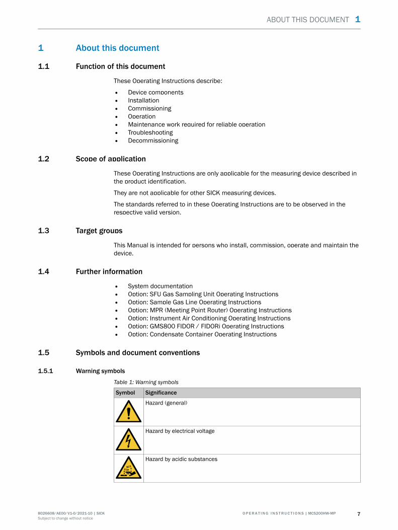
1.5.1 Warning symbols
Table 1: Warning symbols
Symbol Significance
Hazard (general)
Hazard by electrical voltage
Hazard by acidic substances
ABOUT THIS DOCUMENT 1
8026608/AE00/V1-0/2021-10 | SICK O P E R A T I N G I N S T R U C T I O N S | MCS200HW-MP 7Subject to change without notice
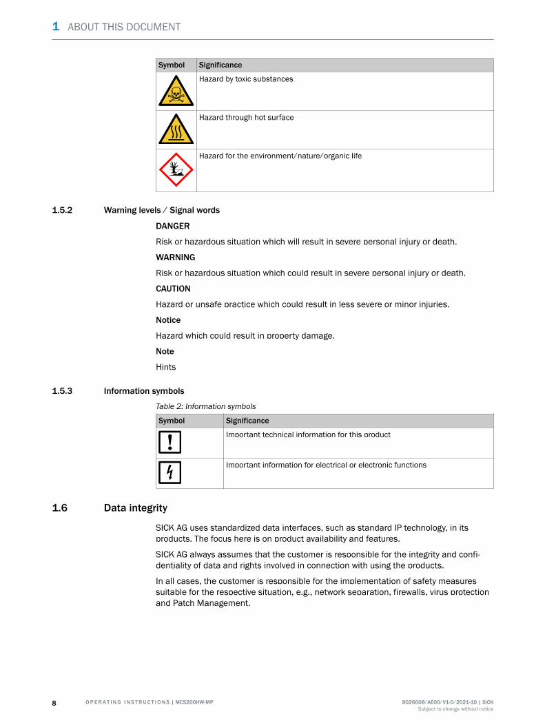
Symbol Significance
Hazard by toxic substances
Hazard through hot surface
Hazard for the environment/nature/organic life
1.5.2 Warning levels / Signal words
DANGER
Risk or hazardous situation which will result in severe personal injury or death.
WARNING
Risk or hazardous situation which could result in severe personal injury or death.
CAUTION
Hazard or unsafe practice which could result in less severe or minor injuries.
Notice
Hazard which could result in property damage.
Note
Hints
1.5.3 Information symbols
Table 2: Information symbols
Symbol Significance
Important technical information for this product
Important information for electrical or electronic functions
1.6 Data integrity
SICK AG uses standardized data interfaces, such as standard IP technology, in itsproducts. The focus here is on product availability and features.
SICK AG always assumes that the customer is responsible for the integrity and confi‐dentiality of data and rights involved in connection with using the products.
In all cases, the customer is responsible for the implementation of safety measuressuitable for the respective situation, e.g., network separation, firewalls, virus protectionand Patch Management.
1 ABOUT THIS DOCUMENT
8 O P E R A T I N G I N S T R U C T I O N S | MCS200HW-MP 8026608/AE00/V1-0/2021-10 | SICKSubject to change without notice
2 Safety information
2.1 Basic safety information
b Read and observe these Operating Instructions.b Observe all safety instructions.b If anything is not clear: Please contact SICK Customer Service.
Document retention
These Operating Instructions
b Must be kept for reference.b Must be passed on to new owners.
Correct project planning
• Basis of this Manual is the delivery of the measuring device according to thepreceding project planning (e.g., based on the SICK application questionnaire)and the relevant delivery state of the measuring device (see delivered SystemDocumentation).b Contact SICK Customer Service if you are not sure whether the measuring
device corresponds to the state defined during project planning or to thedelivered System Documentation.
Correct use
b Use the device only as described in “Intended use”.The manufacturer assumes no responsibility for any other use.
b Carry out the specified maintenance work.b Do not carry out any work or repairs on the device that are not described in this
Manual.Do not remove, add or change any components in or on the device unless suchchanges are officially allowed and specified by the manufacturer.If you do not observe this:
° The manufacturer's warranty becomes void.
° The device could become dangerous.
Special local conditions
In addition to the information in this Manual, follow all local laws, technical rules andcompany-internal operating and installation directives applicable wherever the device isinstalled.
SAFETY INFORMATION 2
8026608/AE00/V1-0/2021-10 | SICK O P E R A T I N G I N S T R U C T I O N S | MCS200HW-MP 9Subject to change without notice
Electrical safety
DANGERDanger to life through electric shockThere is a risk of electric shock when working on the device with the voltage supplyswitched on.
b Before starting work on the device, ensure the voltage supply can be switchedoff in accordance with the valid Standard using a power isolating switch/circuitbreaker.
b Make sure the disconnector switch is easily accessible.b An additional disconnecting device is mandatory when the power disconnector
switch cannot be accessed or only with difficulty after installation of the deviceconnection.
b Switch off the voltage supply before starting any work on the device.b After completion of the work or for test purposes, calibration of the power supply
may only be activated again by authorized personnel complying with the safetyregulations.
WARNINGEndangerment of electrical safety through power supply line with incorrect ratingElectrical accidents can occur when the specifications for installation of a power supplyline have not been adequately observed.
b Always observe the exact specifications in the Operating Instructions (see "Techni‐cal data", page 54) for installation of a power supply line.
Dangerous substances
DANGERDanger to life through leaks in the gas pathWhen the measuring device is used to measure toxic gases: A leak, for example in thepurge air supply, can be an acute hazard for persons..
b Regularly check all gas-carrying components for leaksb Take suitable safety measures. For example:
° Attach warning signs to the device
° Attach warning signs in the operating area
° Adequately vent the operating area.
° Safety-oriented instruction of persons that could be in this area.
2.2 Warning information on device
Warning information on device
The following safety symbols are on the device:
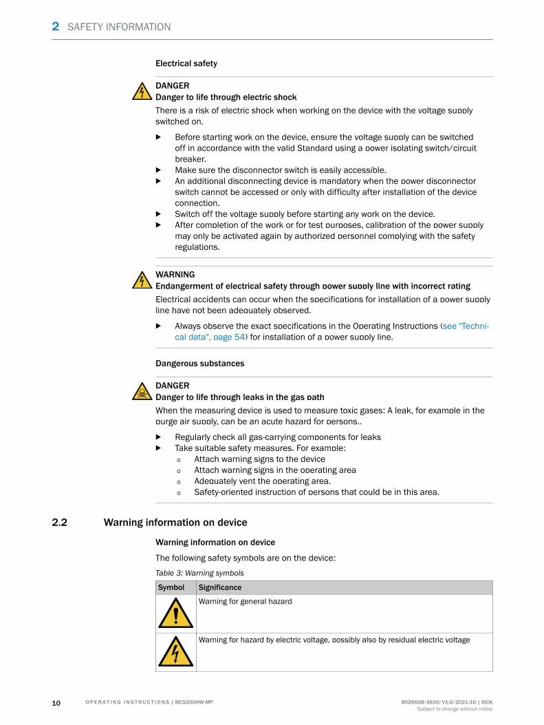
Table 3: Warning symbols
Symbol Significance
Warning for general hazard
Warning for hazard by electric voltage, possibly also by residual electric voltage
2 SAFETY INFORMATION
10 O P E R A T I N G I N S T R U C T I O N S | MCS200HW-MP 8026608/AE00/V1-0/2021-10 | SICKSubject to change without notice
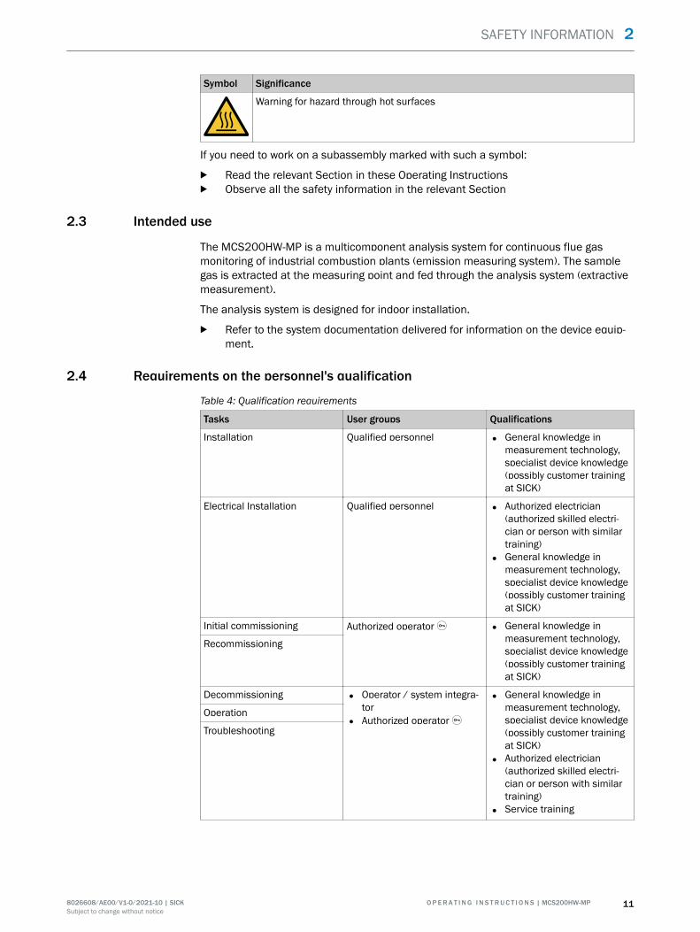
Symbol Significance
Warning for hazard through hot surfaces
If you need to work on a subassembly marked with such a symbol:
b Read the relevant Section in these Operating Instructionsb Observe all the safety information in the relevant Section
2.3 Intended use
The MCS200HW-MP is a multicomponent analysis system for continuous flue gasmonitoring of industrial combustion plants (emission measuring system). The samplegas is extracted at the measuring point and fed through the analysis system (extractivemeasurement).
The analysis system is designed for indoor installation.
b Refer to the system documentation delivered for information on the device equip‐ment.
2.4 Requirements on the personnel's qualification
Table 4: Qualification requirements
Tasks User groups Qualifications
Installation Qualified personnel • General knowledge inmeasurement technology,specialist device knowledge(possibly customer trainingat SICK)
Electrical Installation Qualified personnel • Authorized electrician(authorized skilled electri‐cian or person with similartraining)
• General knowledge inmeasurement technology,specialist device knowledge(possibly customer trainingat SICK)
Initial commissioning Authorized operator Ü • General knowledge inmeasurement technology,specialist device knowledge(possibly customer trainingat SICK)
Recommissioning
Decommissioning • Operator / system integra‐tor
• Authorized operator Ü
• General knowledge inmeasurement technology,specialist device knowledge(possibly customer trainingat SICK)
• Authorized electrician(authorized skilled electri‐cian or person with similartraining)
• Service training
Operation
Troubleshooting
SAFETY INFORMATION 2
8026608/AE00/V1-0/2021-10 | SICK O P E R A T I N G I N S T R U C T I O N S | MCS200HW-MP 11Subject to change without notice
Tasks User groups Qualifications
Maintenance • Operator / system integra‐tor
• Authorized operator Ü
• General knowledge inmeasurement technology,specialist device knowledge(possibly customer trainingat SICK)
• Service training
2 SAFETY INFORMATION
12 O P E R A T I N G I N S T R U C T I O N S | MCS200HW-MP 8026608/AE00/V1-0/2021-10 | SICKSubject to change without notice
3 Product description
3.1 Product identification
Overview
Product name MCS200HW-MP
Manufacturer SICK AGErwin-Sick-Str. 1 · D-79183 Waldkirch · Germany
Type plate Type plates are located on the right on the installation plate.
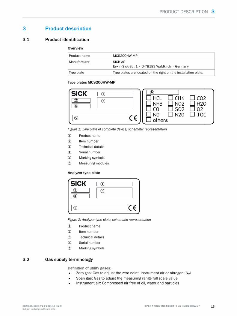
Type plates MCS200HW-MP
Figure 1: Type plate of complete device, schematic representation
1 Product name2 Item number3 Technical details4 Serial number5 Marking symbols6 Measuring modules
Analyzer type plate
Figure 2: Analyzer type plate, schematic representation
1 Product name2 Item number3 Technical details4 Serial number5 Marking symbols
3.2 Gas supply terminology
Definition of utility gases:• Zero gas: Gas to adjust the zero point. Instrument air or nitrogen (N2)• Span gas: Gas to adjust the measuring range full scale value• Instrument air: Compressed air free of oil, water and particles
PRODUCT DESCRIPTION 3
8026608/AE00/V1-0/2021-10 | SICK O P E R A T I N G I N S T R U C T I O N S | MCS200HW-MP 13Subject to change without notice
3.3 Layout and function
3.3.1 System overview
Overview
1
2
3
4
56
7
8
7
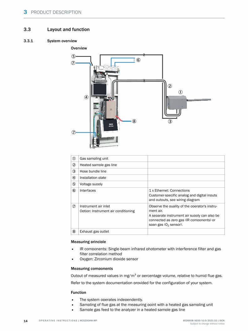
1 Gas sampling unit
2 Heated sample gas line
3 Hose bundle line
4 Installation plate
5 Voltage supply
6 Interfaces 1 x Ethernet: ConnectionsCustomer-specific analog and digital inputsand outputs, see wiring diagram
7 Instrument air inletOption: Instrument air conditioning
Observe the quality of the operator's instru‐ment air.A separate instrument air supply can also beconnected as zero gas (IR components) orspan gas (O2 sensor).
8 Exhaust gas outlet
Measuring principle
• IR components: Single-beam infrared photometer with interference filter and gasfilter correlation method
• Oxygen: Zirconium dioxide sensor
Measuring components
Output of measured values in mg/m³ or percentage volume, relative to humid flue gas.
Refer to the system documentation provided for the configuration of your system.
Function
• The system operates independently.• Sampling of flue gas at the measuring point with a heated gas sampling unit• Sample gas feed to the analyzer in a heated sample gas line
3 PRODUCT DESCRIPTION
14 O P E R A T I N G I N S T R U C T I O N S | MCS200HW-MP 8026608/AE00/V1-0/2021-10 | SICKSubject to change without notice
• Heating temperature of all parts with sample gas contact: 200 °C• Pump: Ejector pump in cell (operated with instrument air)
• The analysis system uses status indicators to signal the current operating state:• The analysis system switches to operating state “System Stop” automatically when
a malfunction occurs“System Stop” corresponds to classification “Failure”:
° The sample gas line and the sample gas path in the analyzer are automati‐cally purged with instrument air in this mode.
° Measured values are updated further.
Check (validation) and adjustment
• Zero point adjustment• Reference point adjustment• Adjustment with internal adjustment filter
Operating using the display
It is possible to operate the device using the display.
Operation via external PC (optional)
Operator menus and measured value displays are also available for easy use on anexternal PC via the Ethernet connection (with Google Chrome browser and SOPASair).
3.3.2 Installation plate
Overview
On the installation plate:
• Control unit• Measurement technology• Analog and digital interfaces
PRODUCT DESCRIPTION 3
8026608/AE00/V1-0/2021-10 | SICK O P E R A T I N G I N S T R U C T I O N S | MCS200HW-MP 15Subject to change without notice
View
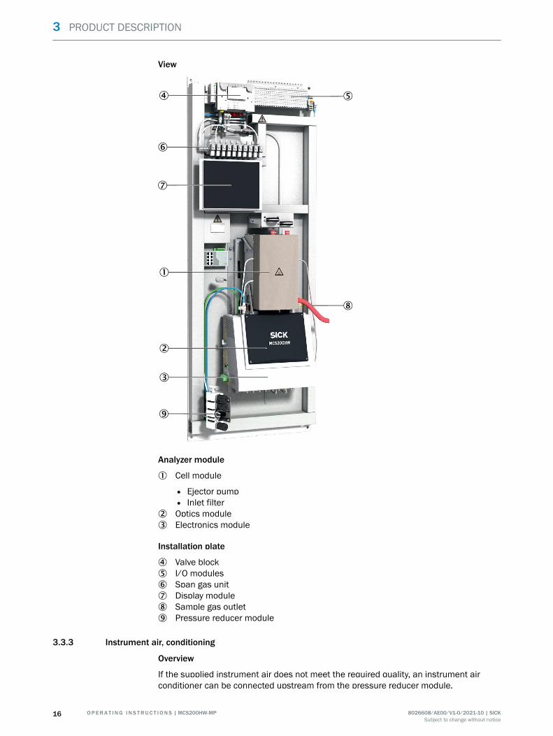
Analyzer module
1 Cell module
• Ejector pump• Inlet filter
2 Optics module3 Electronics module
Installation plate
4 Valve block5 I/O modules6 Span gas unit7 Display module8 Sample gas outlet9 Pressure reducer module
3.3.3 Instrument air, conditioning
Overview
If the supplied instrument air does not meet the required quality, an instrument airconditioner can be connected upstream from the pressure reducer module.
3 PRODUCT DESCRIPTION
16 O P E R A T I N G I N S T R U C T I O N S | MCS200HW-MP 8026608/AE00/V1-0/2021-10 | SICKSubject to change without notice
Important information
NOTICEMalfunction of the measuring device due to unsuitable instrument airOperation with air not satisfying the specifications voids the warranty and does notensure proper functioning of the measuring device.
b Only feed conditioned instrument air to the measuring device.b The instrument air quality must meet the specification.
Function
The instrument air conditioning serves to condition the compressed air provided by theoperator.
Additional information
A separate instrument air supply as zero gas or test gas can be connected as analternative.
Related topics
• Instrument Air Conditioning Operating Instructions• Instrument air quality: see "Gas supply", page 57
3.4 Extended interfaces (option)
As standard, analog and digital signals are used for device communication with cus‐tomer peripherals. Alternatively, output can be performed using the Modbus-TCP proto‐col.
Optionally, SICK offers various converter modules that are installed by the customerand communicate with the device via Modbus® TCP.
Optionally available• PROFIBUS / PROFINET
Modbus
Modbus® is a communication standard for digital controls to create a connectionbetween a »Master« device and several »Slave« devices. The Modbus protocol definesthe communication commands only but not their electronic transfer; therefore it can beused with different digital interfaces (Ethernet).
The measuring device is equipped with a digital interface for data transmission inaccordance with Guideline VDI 4201, Sheet 1 (General requirements) and Sheet 3(Specific requirements for Modbus). Refer to the documentation delivered (Modbussignal list) for assignment of the Modbus registers. Only SICK Service may performparameter settings.
PRODUCT DESCRIPTION 3
8026608/AE00/V1-0/2021-10 | SICK O P E R A T I N G I N S T R U C T I O N S | MCS200HW-MP 17Subject to change without notice
4 Transport and storage
4.1 Transport
Overview
Transport the device horizontally with suitable hoisting equipment (e.g. jack lift withadequate lifting capacity).
Important information
NOTICEThe measuring device may only be transported and installed by qualified persons who,based on their training and knowledge as well as knowledge of the relevant regulations,can assess the tasks given and recognize the dangers involved.
Transport
The device may only be transported horizontally.
The device is picked up with suitable hoisting equipment using the fastening openingson the installation plate.
4.2 Storage
Protective measures for long-term storage
• When gas lines have been unscrewed: Close all gas connections (with sealingplugs) to protect internal gas paths against moisture, dust or dirt penetrating
• Close off open electrical connections dust-tight• Protect the display against sharp-edged objects. Possibly attach a suitable protec‐
tive cover (e.g. made of cardboard or hard foam)• Select a dry, well-ventilated room for storage• Wrap the device (e.g. with stretch foil)• When high air humidity can be expected: Include a drying agent (Silica-Gel) in the
packing
4 TRANSPORT AND STORAGE
18 O P E R A T I N G I N S T R U C T I O N S | MCS200HW-MP 8026608/AE00/V1-0/2021-10 | SICKSubject to change without notice
5 Mounting
5.1 Safety
Qualification
The measuring device may only be installed by trained specialists.
5.2 Scope of delivery
Please see the delivery documents for the scope of delivery.
5.3 Overview of mechanical and electrical installation
Important information
NOTICEObserve the order of assembly.If the assembly sequence is incorrect, there is a risk of contamination of the gas sam‐pling unit. This can cause exhaust gas to enter the unheated analyzer and condenseout.
b First connect instrument air and voltage supply.b Only then install the gas sampling unit in the flue gas duct.
Installation sequence
• Fit the installation plate• Electrical connections on analyzer• Connect signal lines to analyzer• Install SFU gas sampling system• Connect heater hose• Air and gas connections on analyzer• Connect sample gas line to analyzer• Sample gas outlet
MOUNTING 5
8026608/AE00/V1-0/2021-10 | SICK O P E R A T I N G I N S T R U C T I O N S | MCS200HW-MP 19Subject to change without notice
5.4 Installation sequence
5.4.1 Wall mounting
Overview
23
1.8
47
1.8
23
598
666
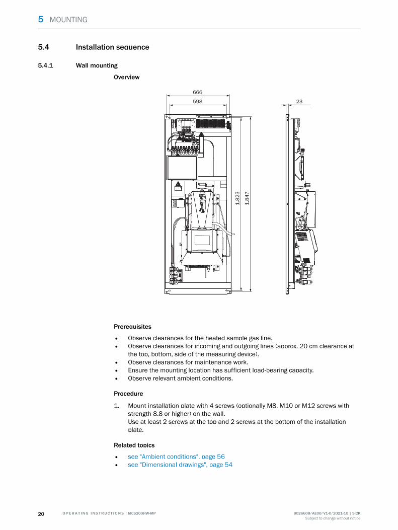
Prerequisites
• Observe clearances for the heated sample gas line.• Observe clearances for incoming and outgoing lines (approx. 20 cm clearance at
the top, bottom, side of the measuring device).• Observe clearances for maintenance work.• Ensure the mounting location has sufficient load-bearing capacity.• Observe relevant ambient conditions.
Procedure
1. Mount installation plate with 4 screws (optionally M8, M10 or M12 screws withstrength 8.8 or higher) on the wall.Use at least 2 screws at the top and 2 screws at the bottom of the installationplate.
Related topics
• see "Ambient conditions", page 56• see "Dimensional drawings", page 54
5 MOUNTING
20 O P E R A T I N G I N S T R U C T I O N S | MCS200HW-MP 8026608/AE00/V1-0/2021-10 | SICKSubject to change without notice
5.4.2 Installing the sample gas line
5.4.2.1 Laying the sample gas lines
Overview
1
5
4
7
6
3 2
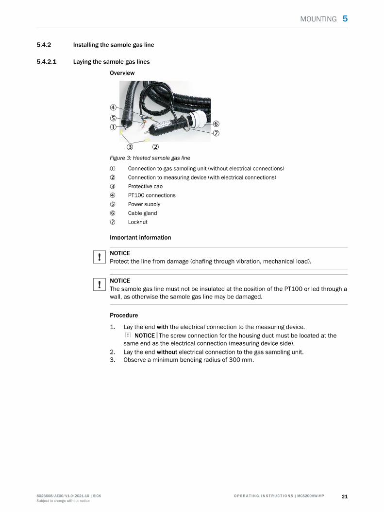
Figure 3: Heated sample gas line
1 Connection to gas sampling unit (without electrical connections)2 Connection to measuring device (with electrical connections)3 Protective cap4 PT100 connections5 Power supply6 Cable gland7 Locknut
Important information
NOTICEProtect the line from damage (chafing through vibration, mechanical load).
NOTICEThe sample gas line must not be insulated at the position of the PT100 or led through awall, as otherwise the sample gas line may be damaged.
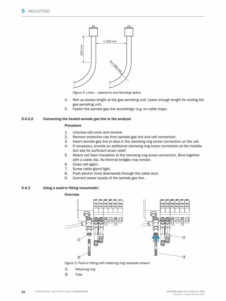
Procedure
1. Lay the end with the electrical connection to the measuring device.NOTICE The screw connection for the housing duct must be located at the
same end as the electrical connection (measuring device side).2. Lay the end without electrical connection to the gas sampling unit.3. Observe a minimum bending radius of 300 mm.
MOUNTING 5
8026608/AE00/V1-0/2021-10 | SICK O P E R A T I N G I N S T R U C T I O N S | MCS200HW-MP 21Subject to change without notice
≥ 100 mm
25
0 m
m
R ≥ 3
00 m
m
Figure 4: Lines – clearance and bending radius
4. Roll up excess length at the gas sampling unit. Leave enough length for pulling thegas sampling unit.
5. Fasten the sample gas line accordingly (e.g. on cable trays).
5.4.2.2 Connecting the heated sample gas line to the analyzer
Procedure
1. Unscrew cell cover and remove.2. Remove protective cap from sample gas line and cell connection.3. Insert sample gas line to stop in the clamping ring screw connection on the cell.4. If necessary, provide an additional clamping ring screw connection at the installa‐
tion site for sufficient strain relief.5. Attach red foam insulation to the clamping ring screw connection. Bind together
with a cable clip. No thermal bridges may remain.6. Close cell again.7. Screw cable gland tight.8. Push electric lines downwards through the cable duct.9. Connect power supply of the sample gas line.
5.4.3 Using a push-in fitting (pneumatic)
Overview
Figure 5: Push-in fitting with retaining ring (example shown)
1 Retaining ring2 Tube
5 MOUNTING
22 O P E R A T I N G I N S T R U C T I O N S | MCS200HW-MP 8026608/AE00/V1-0/2021-10 | SICKSubject to change without notice
Procedure
Fitting the tube1. Push the tube in.
Removing the tube1. Press the retaining ring in.2. Pull the tube out.
5.4.4 Laying the hose bundle line
Important information
NOTICEProtect the line from damage (chafing through vibration, mechanical load).
Procedure
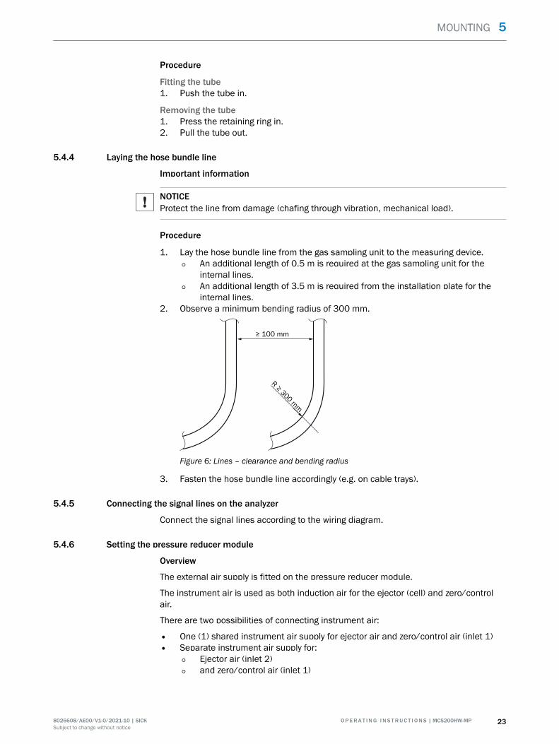
1. Lay the hose bundle line from the gas sampling unit to the measuring device.
° An additional length of 0.5 m is required at the gas sampling unit for theinternal lines.
° An additional length of 3.5 m is required from the installation plate for theinternal lines.
2. Observe a minimum bending radius of 300 mm.
≥ 100 mm
R ≥ 3
00 m
m
Figure 6: Lines – clearance and bending radius
3. Fasten the hose bundle line accordingly (e.g. on cable trays).
5.4.5 Connecting the signal lines on the analyzer
Connect the signal lines according to the wiring diagram.
5.4.6 Setting the pressure reducer module
Overview
The external air supply is fitted on the pressure reducer module.
The instrument air is used as both induction air for the ejector (cell) and zero/controlair.
There are two possibilities of connecting instrument air:
• One (1) shared instrument air supply for ejector air and zero/control air (inlet 1)• Separate instrument air supply for:
° Ejector air (inlet 2)
° and zero/control air (inlet 1)
MOUNTING 5
8026608/AE00/V1-0/2021-10 | SICK O P E R A T I N G I N S T R U C T I O N S | MCS200HW-MP 23Subject to change without notice
100
BAR100
BAR100
BAR
3 bar
6 bar
4 bar
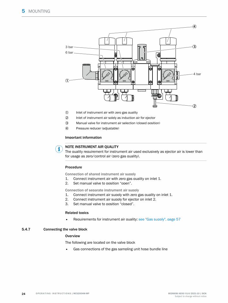
1 Inlet of instrument air with zero gas quality2 Inlet of instrument air solely as induction air for ejector3 Manual valve for instrument air selection (closed position)4 Pressure reducer (adjustable)
Important information
NOTE INSTRUMENT AIR QUALITYThe quality requirement for instrument air used exclusively as ejector air is lower thanfor usage as zero/control air (zero gas quality).
Procedure
Connection of shared instrument air supply1. Connect instrument air with zero gas quality on inlet 1.2. Set manual valve to position “open”.
Connection of separate instrument air supply1. Connect instrument air supply with zero gas quality on inlet 1.2. Connect instrument air supply for ejector on inlet 2.3. Set manual valve to position “closed”.
Related topics
• Requirements for instrument air quality: see "Gas supply", page 57
5.4.7 Connecting the valve block
Overview
The following are located on the valve block
• Gas connections of the gas sampling unit hose bundle line
5 MOUNTING
24 O P E R A T I N G I N S T R U C T I O N S | MCS200HW-MP 8026608/AE00/V1-0/2021-10 | SICKSubject to change without notice
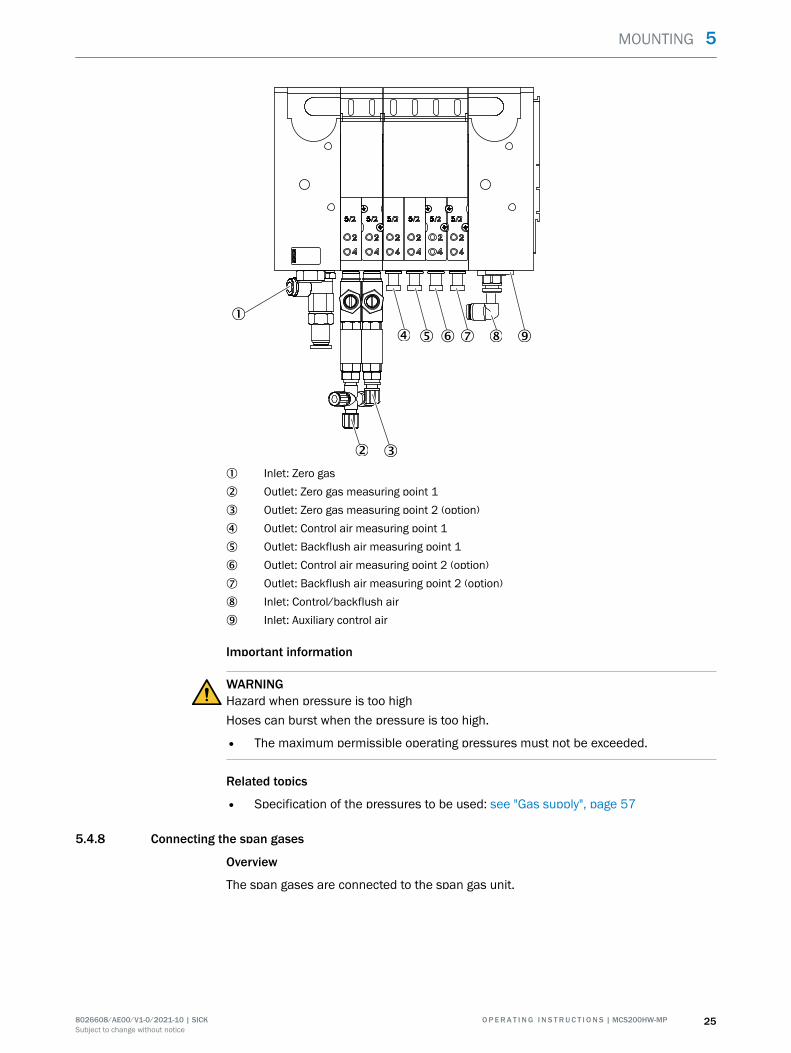
1 Inlet: Zero gas2 Outlet: Zero gas measuring point 13 Outlet: Zero gas measuring point 2 (option)4 Outlet: Control air measuring point 15 Outlet: Backflush air measuring point 16 Outlet: Control air measuring point 2 (option)7 Outlet: Backflush air measuring point 2 (option)8 Inlet: Control/backflush air9 Inlet: Auxiliary control air
Important information
WARNINGHazard when pressure is too highHoses can burst when the pressure is too high.
• The maximum permissible operating pressures must not be exceeded.
Related topics
• Specification of the pressures to be used: see "Gas supply", page 57
5.4.8 Connecting the span gases
Overview
The span gases are connected to the span gas unit.
MOUNTING 5
8026608/AE00/V1-0/2021-10 | SICK O P E R A T I N G I N S T R U C T I O N S | MCS200HW-MP 25Subject to change without notice
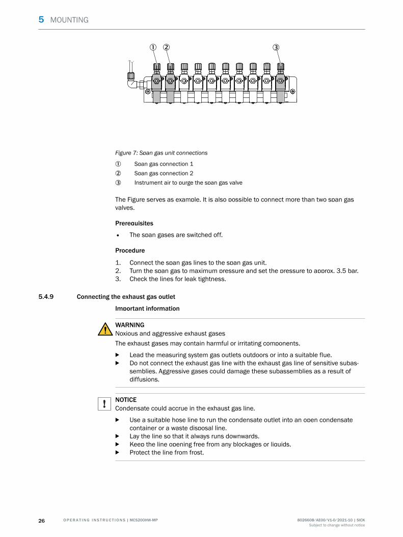
Figure 7: Span gas unit connections
1 Span gas connection 12 Span gas connection 23 Instrument air to purge the span gas valve
The Figure serves as example. It is also possible to connect more than two span gasvalves.
Prerequisites
• The span gases are switched off.
Procedure
1. Connect the span gas lines to the span gas unit.2. Turn the span gas to maximum pressure and set the pressure to approx. 3.5 bar.3. Check the lines for leak tightness.
5.4.9 Connecting the exhaust gas outlet
Important information
WARNINGNoxious and aggressive exhaust gasesThe exhaust gases may contain harmful or irritating components.
b Lead the measuring system gas outlets outdoors or into a suitable flue.b Do not connect the exhaust gas line with the exhaust gas line of sensitive subas‐
semblies. Aggressive gases could damage these subassemblies as a result ofdiffusions.
NOTICECondensate could accrue in the exhaust gas line.
b Use a suitable hose line to run the condensate outlet into an open condensatecontainer or a waste disposal line.
b Lay the line so that it always runs downwards.b Keep the line opening free from any blockages or liquids.b Protect the line from frost.
5 MOUNTING
26 O P E R A T I N G I N S T R U C T I O N S | MCS200HW-MP 8026608/AE00/V1-0/2021-10 | SICKSubject to change without notice

Procedure
1. Connect the exhaust gas outlet at the intended place.2. Lay the exhaust gas line in a suitable manner:
° The gas outlet must be open to the ambient pressure; in waste disposal linesit can be laid with a light partial vacuum.
° Do not bend or crimp exhaust gas lines.
MOUNTING 5
8026608/AE00/V1-0/2021-10 | SICK O P E R A T I N G I N S T R U C T I O N S | MCS200HW-MP 27Subject to change without notice
6 Electrical installation
6.1 Safety
Qualification
The measuring device may only be installed by trained specialists.
6.2 Equipment protection
Short-circuit protection must be provided by the customer in accordance with theapplicable standards by means of fuses or circuit breakers with short-circuit protectionand overload protection.
6.3 Disconnecting device
Install a power isolating switch or circuit breaker according to the valid standard fordisconnecting the voltage supply.
Install an additional disconnecting device if a UPS is used.
Make sure the power isolating switches are easily accessible.
6.4 Socket for Service work
It is recommended to install a socket in accordance with the applicable standards nearthe measuring device for service work.
6.5 Connecting the power supply
Overview
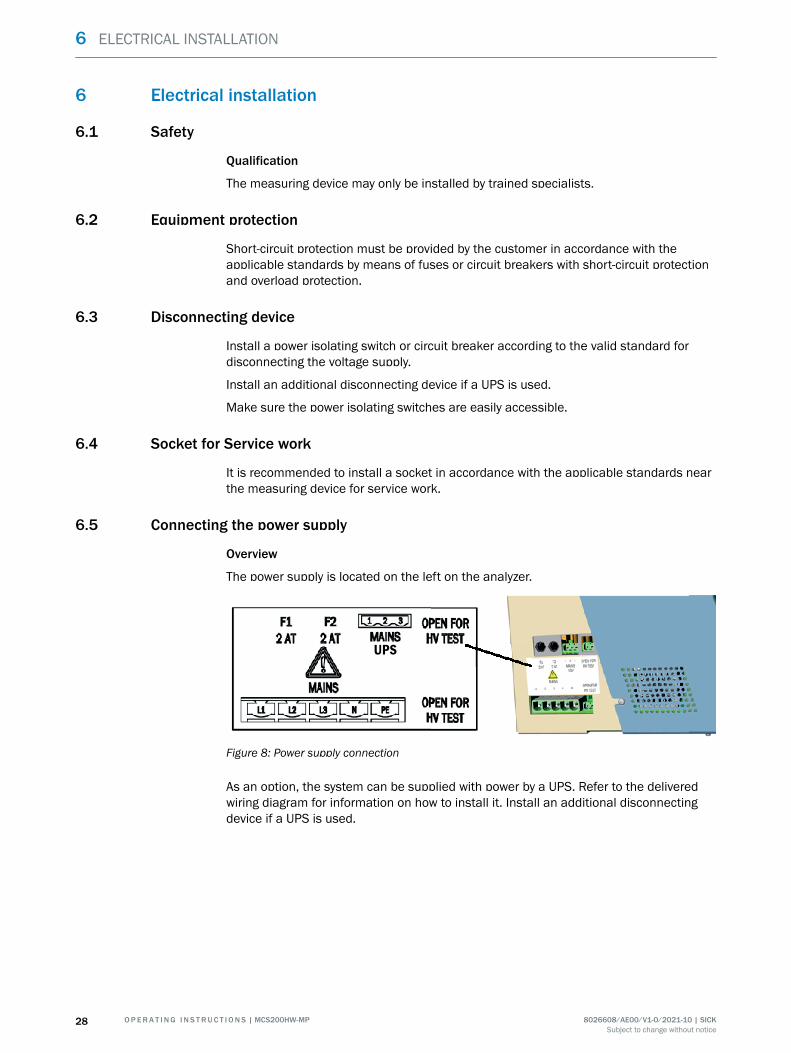
The power supply is located on the left on the analyzer.
UPS
Figure 8: Power supply connection
As an option, the system can be supplied with power by a UPS. Refer to the deliveredwiring diagram for information on how to install it. Install an additional disconnectingdevice if a UPS is used.
6 ELECTRICAL INSTALLATION
28 O P E R A T I N G I N S T R U C T I O N S | MCS200HW-MP 8026608/AE00/V1-0/2021-10 | SICKSubject to change without notice
Important information
NOTICE
• Install an external power disconnection unit which disconnects all connectors andfuses near the analyzer.
• The power disconnection unit must be marked clearly and be easily accessible.• The onsite wiring system to the power source of the system must be installed and
fused according to the relevant regulations.• Always connect a protective ground to PE.
Procedure
1. Connect the electric lines.
6.6 Performing a high voltage test
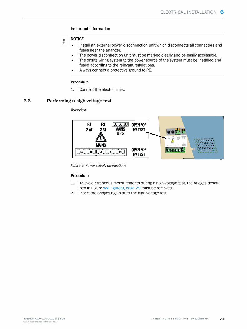
Overview
UPS
Figure 9: Power supply connections
Procedure
1. To avoid erroneous measurements during a high-voltage test, the bridges descri‐bed in Figure see figure 9, page 29 must be removed.
2. Insert the bridges again after the high-voltage test.
ELECTRICAL INSTALLATION 6
8026608/AE00/V1-0/2021-10 | SICK O P E R A T I N G I N S T R U C T I O N S | MCS200HW-MP 29Subject to change without notice
7 Commissioning
7.1 Prerequisites for switching on
Procedure
1. Check the measuring device.2. Instrument air must be connected and open.3. If the instrument air has changed: Check the instrument air quality.4. Check pressure settings on the pressure reducer unit.
Related topics
• Measuring device check: see "Checking the system", page 44• Instrument air quality: see "Gas supply", page 57• Pressure reducer unit setting: see "Setting the pressure reducer module", page 23
7.2 Switching on
Procedure
1. Switch on the external power disconnection unit.✓ SOPASair loading screen is displayed.✓ A countdown is shown on the display, counting down from 80.✓ The start screen opens. Display: System initialization✓ The measuring device heats up:Display: System heats.The status indicator is
orange. Heating process can take up to 2 hours.✓ Display: Premeasure. The status indicator is orange.✓ The status indicator is green. Display: Measure.The measuring device is ready for
operation.2. When the yellow or red status indicator is on: Display logbook and clear error.✓ The measuring device is in operation.
Related topics
• Error list: see "Error messages and possible causes", page 47
7.3 Recognizing the safe operating state
The system is in proper operation when:
• A system check has been carried out according to the Maintenance plan beforecommissioning and in running operation.
• Only the green status indicator is on and Measuring is shown in the status bar.When the yellow or red status indicator is on: Display logbook and clear error.
Related topics
• Checking the system: see "Checking the system", page 44• Error list: see "Error messages and possible causes", page 47
7.4 Adjusting
7.4.1 Performing zero point adjustment
Overview
Menu: Tasks →Zero point adjustment
As standard, the zero point adjustment is used to adjust the zero points of the meas‐ured values while instrument air is fed.
7 COMMISSIONING
30 O P E R A T I N G I N S T R U C T I O N S | MCS200HW-MP 8026608/AE00/V1-0/2021-10 | SICKSubject to change without notice
Zero point adjustment runs cyclically (preset) but can also be started manually.
If the deviation is higher than a specified limit value, the system switches to classifica‐tion “Maintenance request” and the zero point is however corrected.
Procedure
1. Click tile “Zero point adjustment”.✓ The operating state switches to zero point adjustment.✓ The respective active step is displayed.✓ The time elapsed and the remaining time of the state and of the respective active
step is displayed.2. The system switches back to original state automatically when adjustment has
been completed.
7.4.2 Performing reference point adjustment
7.4.2.1 Adjustment with internal adjustment filter
Overview
Menu: Tasks → Adjustment with internal adjustment filter
During adjustment, concentrations of measuring components are adjusted with anadjustment filter.
Procedure
1. Click tile “Adjustment with internal adjustment filter”.✓ The operating state switches to adjustment with internal adjustment filter.✓ The respective active step is displayed.✓ The time elapsed and the remaining time of the state and of the respective active
step is displayed.2. The system switches back to original state automatically when adjustment has
been completed.
7.4.2.2 Adjustment with span gas
Overview
Menu: Tasks → Reference point adjustment
During adjustment, the concentrations of the respective measuring component areadjusted using span gas.
Procedure
1. Compare the span gas concentration set with the certificate of the span gascylinder and, when necessary, change it in the device: Tasks→ Reference pointadjustment - Concentrations.
2. Perform manual update.3. Use the arrow button to go to the next Figure.4. Start adjustment with “Reference point adjustment”.✓ The operating state switches to reference point adjustment.✓ The time elapsed and the remaining time of the state and of the respective active
step is displayed.5. The system switches back to original state automatically when adjustment has
been completed.
COMMISSIONING 7
8026608/AE00/V1-0/2021-10 | SICK O P E R A T I N G I N S T R U C T I O N S | MCS200HW-MP 31Subject to change without notice
7.4.2.3 O2 adjustment
Overview
Menu: 2 adjustment→ 1 adjustment → O2 adjustment
During adjustment, the concentrations of the respective measuring component areadjusted using instrument air as standard.
Procedure
1. Start adjustment with “O2 adjustment”.✓ The operating state switches to O2 adjustment.✓ The time elapsed and the remaining time of the state and of the respective active
step is displayed.2. The system switches back to original state automatically when adjustment has
been completed.
7 COMMISSIONING
32 O P E R A T I N G I N S T R U C T I O N S | MCS200HW-MP 8026608/AE00/V1-0/2021-10 | SICKSubject to change without notice
8 Operation
8.1 Operating concept
The analysis system is equipped with a display with touchscreen.
• All menus and functions are shown on the display.• The menus and functions are called up using the tiles.• The current operating state is displayed by the status indicator (Namur).
8.2 User groups
Depending on the user group, different menus are visible on the device.
User group Task
Operator System monitoring regarding measured values and status
Authorized client Configuration, simple error clearance and maintenance
8.3 Display
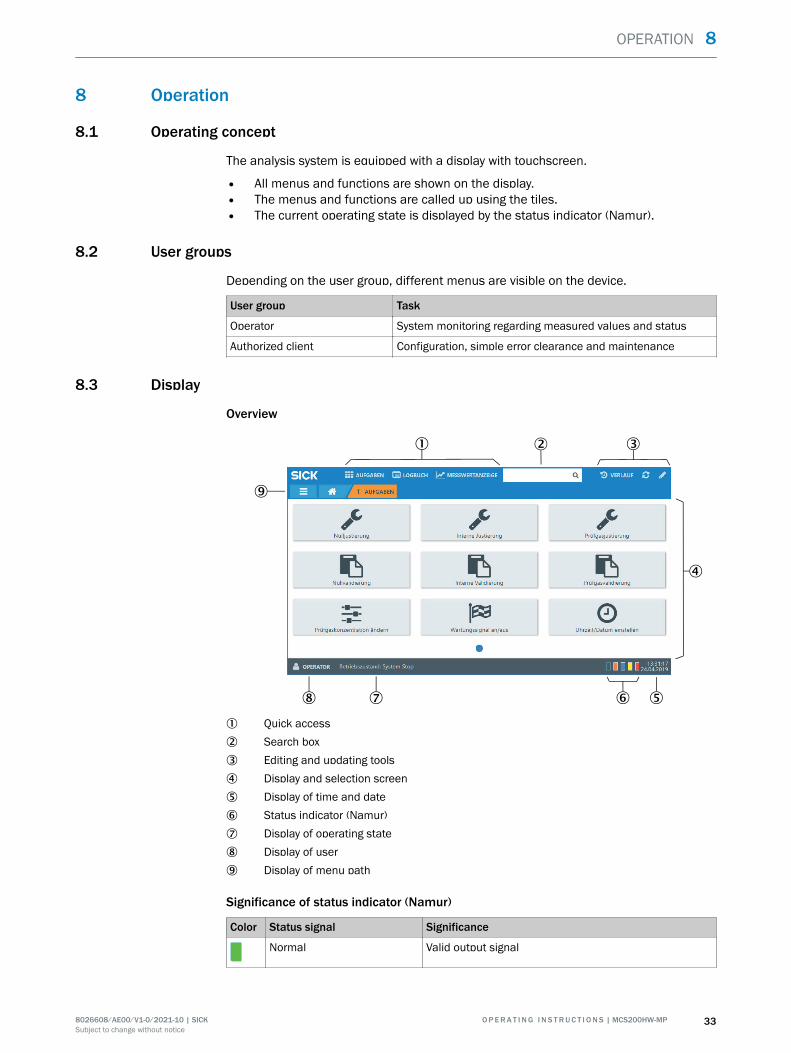
Overview
1 Quick access2 Search box3 Editing and updating tools4 Display and selection screen5 Display of time and date6 Status indicator (Namur)7 Display of operating state8 Display of user9 Display of menu path
Significance of status indicator (Namur)
Color Status signal Significance
Normal Valid output signal
OPERATION 8
8026608/AE00/V1-0/2021-10 | SICK O P E R A T I N G I N S T R U C T I O N S | MCS200HW-MP 33Subject to change without notice
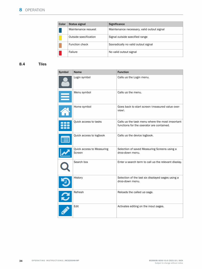
Color Status signal Significance
Maintenance request Maintenance necessary, valid output signal
Outside specification Signal outside specified range
Function check Sporadically no valid output signal
Failure No valid output signal
8.4 Tiles
Symbol Name Function
Login symbol Calls up the Login menu.
Menu symbol Calls up the menu.
Home symbol Goes back to start screen (measured value over‐view).
Quick access to tasks Calls up the task menu where the most importantfunctions for the operator are contained.
Quick access to logbook Calls up the device logbook.
Quick access to MeasuringScreen
Selection of saved Measuring Screens using adrop-down menu.
Search box Enter a search term to call up the relevant display.
History Selection of the last six displayed pages using adrop-down menu.
Refresh Reloads the called up page.
Edit Activates editing on the input pages.
8 OPERATION
34 O P E R A T I N G I N S T R U C T I O N S | MCS200HW-MP 8026608/AE00/V1-0/2021-10 | SICKSubject to change without notice
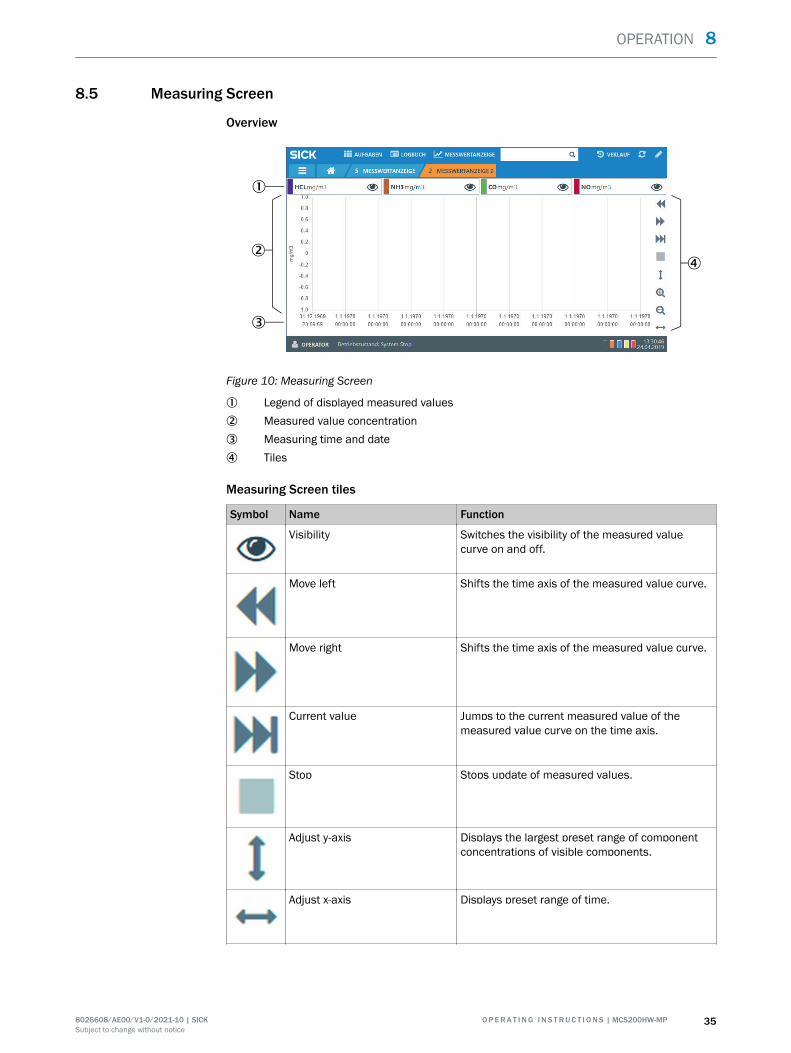
8.5 Measuring Screen
Overview
Figure 10: Measuring Screen
1 Legend of displayed measured values2 Measured value concentration3 Measuring time and date4 Tiles
Measuring Screen tiles
Symbol Name Function
Visibility Switches the visibility of the measured valuecurve on and off.
Move left Shifts the time axis of the measured value curve.
Move right Shifts the time axis of the measured value curve.
Current value Jumps to the current measured value of themeasured value curve on the time axis.
Stop Stops update of measured values.
Adjust y-axis Displays the largest preset range of componentconcentrations of visible components.
Adjust x-axis Displays preset range of time.
OPERATION 8
8026608/AE00/V1-0/2021-10 | SICK O P E R A T I N G I N S T R U C T I O N S | MCS200HW-MP 35Subject to change without notice
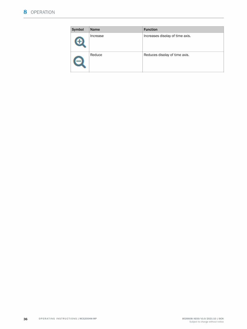
Symbol Name Function
Increase Increases display of time axis.
Reduce Reduces display of time axis.
8 OPERATION
36 O P E R A T I N G I N S T R U C T I O N S | MCS200HW-MP 8026608/AE00/V1-0/2021-10 | SICKSubject to change without notice
9 Menus
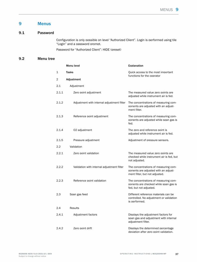
9.1 Password
Configuration is only possible on level “Authorized Client”. Login is performed using tile“Login” and a password prompt.
Password for “Authorized Client”: HIDE (preset)
9.2 Menu tree
Menu level Explanation
1 Tasks Quick access to the most importantfunctions for the operator
2 Adjustment
2.1 Adjustment
2.1.1 Zero point adjustment The measured value zero points areadjusted while instrument air is fed.
2.1.2 Adjustment with internal adjustment filter The concentrations of measuring com‐ponents are adjusted with an adjust‐ment filter.
2.1.3 Reference point adjustment The concentrations of measuring com‐ponents are adjusted while span gas isfed.
2.1.4 O2 adjustment The zero and reference point isadjusted while instrument air is fed.
2.1.5 Pressure adjustment Adjustment of pressure sensors.
2.2 Validation
2.2.1 Zero point validation The measured value zero points arechecked while instrument air is fed, butnot adjusted.
2.2.2 Validation with internal adjustment filter The concentrations of measuring com‐ponents are adjusted with an adjust‐ment filter, but not adjusted.
2.2.3 Reference point validation The concentrations of measuring com‐ponents are checked while span gas isfed, but not adjusted.
2.3 Span gas feed Different reference materials can becontrolled. No adjustment or validationis performed.
2.4 Results
2.4.1 Adjustment factors Displays the adjustment factors forspan gas and adjustment with internaladjustment filter.
2.4.2 Zero point drift Displays the determined percentagedeviation after zero point validation.
MENUS 9
8026608/AE00/V1-0/2021-10 | SICK O P E R A T I N G I N S T R U C T I O N S | MCS200HW-MP 37Subject to change without notice

2.4.3 Reference point drift (internal adjustmentfilter)
Displays the determined percentagedeviation of measuring component con‐centration after validation with anadjustment filter.
2.4.4 Reference point drift (span gas) Displays the determined percentagedeviation of measuring component con‐centration after validation with spangas.
2.5 Settings
2.5.1 Span gas concentrations Entry fields for updating the span gasconcentrations.
2.5.2 Component-specific parameters Displays the parameters of the individ‐ual measuring components.
2.5.3 Parameters Displays general parameters andparameters relevant for adjustment.
2.5.4 Cyclic triggers Displays configured start times ofsequences.
3 Diagnosis
3.1 Status Displays device information and thecurrent status.
3.2 Logbooks
3.2.1 Device logbook Logbook of pending messages and sta‐tus with start and end date.
3.2.2 Customer protocol Tile “Edit” allows entries by operatorand maintenance personnel.
3.3 Device state data
3.3.1 Operating hours counter Displays operating hours.
3.3.2 Temperatures Displays temperatures and their status.
3.3.3 IR source Displays IR source status.
3.3.4 Motors Displays motor values.
3.3.5 Pressure Displays current pressures.
3.3.6 Flow rate Displays flow rates and their status.
3.3.7 Hardware monitoring Displays values and hardware status.
3.3.8 O2 sensor Displays values and O2 sensor status.
3.3.9 Reference energy Displays reference energy of the individ‐ual measuring components.
3.3.10 Intensity Displays intensities of measuring filtersand reference filters.
3.4 Interfaces
3.4.1 Analog outputs Displays current mA of the individualanalog outputs.
9 MENUS
38 O P E R A T I N G I N S T R U C T I O N S | MCS200HW-MP 8026608/AE00/V1-0/2021-10 | SICKSubject to change without notice
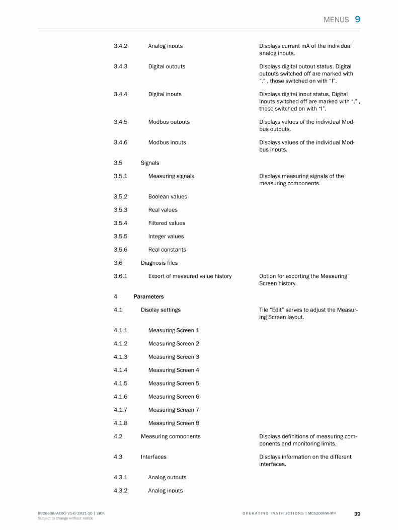
3.4.2 Analog inputs Displays current mA of the individualanalog inputs.
3.4.3 Digital outputs Displays digital output status. Digitaloutputs switched off are marked with“.” , those switched on with “I”.
3.4.4 Digital inputs Displays digital input status. Digitalinputs switched off are marked with “.” ,those switched on with “I”.
3.4.5 Modbus outputs Displays values of the individual Mod‐bus outputs.
3.4.6 Modbus inputs Displays values of the individual Mod‐bus inputs.
3.5 Signals
3.5.1 Measuring signals Displays measuring signals of themeasuring components.
3.5.2 Boolean values
3.5.3 Real values
3.5.4 Filtered values
3.5.5 Integer values
3.5.6 Real constants
3.6 Diagnosis files
3.6.1 Export of measured value history Option for exporting the MeasuringScreen history.
4 Parameters
4.1 Display settings Tile “Edit” serves to adjust the Measur‐ing Screen layout.
4.1.1 Measuring Screen 1
4.1.2 Measuring Screen 2
4.1.3 Measuring Screen 3
4.1.4 Measuring Screen 4
4.1.5 Measuring Screen 5
4.1.6 Measuring Screen 6
4.1.7 Measuring Screen 7
4.1.8 Measuring Screen 8
4.2 Measuring components Displays definitions of measuring com‐ponents and monitoring limits.
4.3 Interfaces Displays information on the differentinterfaces.
4.3.1 Analog outputs
4.3.2 Analog inputs
MENUS 9
8026608/AE00/V1-0/2021-10 | SICK O P E R A T I N G I N S T R U C T I O N S | MCS200HW-MP 39Subject to change without notice
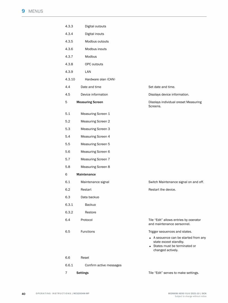
4.3.3 Digital outputs
4.3.4 Digital inputs
4.3.5 Modbus outputs
4.3.6 Modbus inputs
4.3.7 Modbus
4.3.8 OPC outputs
4.3.9 LAN
4.3.10 Hardware plan (CAN)
4.4 Date and time Set date and time.
4.5 Device information Displays device information.
5 Measuring Screen Displays individual preset MeasuringScreens.
5.1 Measuring Screen 1
5.2 Measuring Screen 2
5.3 Measuring Screen 3
5.4 Measuring Screen 4
5.5 Measuring Screen 5
5.6 Measuring Screen 6
5.7 Measuring Screen 7
5.8 Measuring Screen 8
6 Maintenance
6.1 Maintenance signal Switch Maintenance signal on and off.
6.2 Restart Restart the device.
6.3 Data backup
6.3.1 Backup
6.3.2 Restore
6.4 Protocol Tile “Edit” allows entries by operatorand maintenance personnel.
6.5 Functions Trigger sequences and states.
• A sequence can be started from anystate except standby.
• States must be terminated orchanged actively.
6.6 Reset
6.6.1 Confirm active messages
7 Settings Tile “Edit” serves to make settings.
9 MENUS
40 O P E R A T I N G I N S T R U C T I O N S | MCS200HW-MP 8026608/AE00/V1-0/2021-10 | SICKSubject to change without notice
10 Maintenance
10.1 Safety
Requirements for the maintenance personnel
• Only allow an authorized electrician to work on the electrical system or electricalsubassemblies.
• The technician must be familiar with the exhaust gas technology of the operator'splant (hazard by overpressure and toxic and hot flue gases) and be able to avoidhazards when working on gas ducts.
• The technician must be familiar with handling compressed gas cylinders (testgases).
• The technician must be able to avoid hazards caused by noxious test gases.• The technician must be familiar with gas lines and their screw fittings (be able to
ensure gas-tight connections).
10.2 Important information
Electric voltage
DANGERDanger to life through electric shockThere is a risk of electric shock when working on the device with the voltage supplyswitched on.
b Before starting work on the device, ensure the voltage supply can be switchedoff in accordance with the valid standard using a power isolating switch/circuitbreaker.
b Switch off the voltage supply before starting any work on the device.b After completion of the work or for test purposes or calibration, the power supply
may only be activated again by authorized personnel complying with the safetyregulations.
NOTICERisk of destruction of electronic components by electrostatic discharge (ESD)When electronic assemblies are touched, there is a risk of the assembly beingdestroyed by electrical equipotential bonding.
b Make sure you have the same electric potential as the assembly (e.g. by ground‐ing) before touching the assembly.
NOTICEObserve voltage variantSome spare parts are available in different voltage variants, 115 V or 230 V.The power voltage of your system is shown on the type plate.
b Check spare parts for voltage dependency before fitting:
MAINTENANCE 10
8026608/AE00/V1-0/2021-10 | SICK O P E R A T I N G I N S T R U C T I O N S | MCS200HW-MP 41Subject to change without notice
Sample gases and exhaust gases
CAUTIONRisk of chemical burns by acid gasAcid condensate could escape when working on the sample gas lines and the associ‐ated assemblies.
b Take appropriate protective measures for work (e.g., by wearing a safety mask,protective gloves and acid resistant clothes)
b In case of contact with the eyes, rinse immediately with clear water and consult adoctor.
NOTICERisk of contamination of analyzerThe gas sampling unit and analyzer are flushed with instrument air when the system isnot in measuring operation. When the instrument air is switched off, there is the risk ofcontamination of the analyzer.
• Pull the gas sampling unit out of the exhaust duct when instrument air is notavailable for a longer period of time.
Surfaces
CAUTION DANGER OF BURNS DUE TO HOT SURFACESSurface can become hot through operation of the device.
b Wear suitable protective clothes, for example, heat-resistant gloves.b Switch off the device and allow the components to cool down.
Span gases
CAUTIONBefore working on span gas cylinders or span gas lines: Relieve the span gas pressure.
b Shut off the span gas cylinder.b Open the span gas valve: Menu: 2 Adjustment → 3 Span gas feed.b Wait for about 1 minute until the pressure in the lines has been relieved.b Close the span gas valve: Menu: 2 Adjustment → 3 Span gas feed.
Please note:
• After working on the gas path: Perform a leak tightness check.• After exchanging a span gas cylinder: Check the compliance with the span gas
concentration set in the menu: 2 Adjustment → 5 Settings → 1 Concentrations
10.3 Maintenance plan
Overview
This Maintenance plan describes the maintenance work specified by the manufacturer.
Perform checks in accordance with the guidelines to be applied by the operator inaccordance with the intervals described therein.
10 MAINTENANCE
42 O P E R A T I N G I N S T R U C T I O N S | MCS200HW-MP 8026608/AE00/V1-0/2021-10 | SICKSubject to change without notice
Maintenance intervals
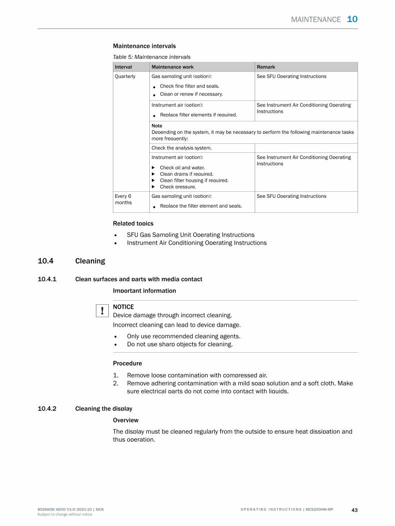
Table 5: Maintenance intervals
Interval Maintenance work Remark
Quarterly Gas sampling unit (option):
• Check fine filter and seals.
• Clean or renew if necessary.
See SFU Operating Instructions
Instrument air (option):
• Replace filter elements if required.
See Instrument Air Conditioning OperatingInstructions
NoteDepending on the system, it may be necessary to perform the following maintenance tasksmore frequently:
Check the analysis system.
Instrument air (option):
b Check oil and water.b Clean drains if required.b Clean filter housing if required.b Check pressure.
See Instrument Air Conditioning OperatingInstructions
Every 6months
Gas sampling unit (option):
• Replace the filter element and seals.
See SFU Operating Instructions
Related topics
• SFU Gas Sampling Unit Operating Instructions• Instrument Air Conditioning Operating Instructions
10.4 Cleaning
10.4.1 Clean surfaces and parts with media contact
Important information
NOTICEDevice damage through incorrect cleaning.Incorrect cleaning can lead to device damage.
• Only use recommended cleaning agents.• Do not use sharp objects for cleaning.
Procedure
1. Remove loose contamination with compressed air.2. Remove adhering contamination with a mild soap solution and a soft cloth. Make
sure electrical parts do not come into contact with liquids.
10.4.2 Cleaning the display
Overview
The display must be cleaned regularly from the outside to ensure heat dissipation andthus operation.
MAINTENANCE 10
8026608/AE00/V1-0/2021-10 | SICK O P E R A T I N G I N S T R U C T I O N S | MCS200HW-MP 43Subject to change without notice
Important information
NOTICEDevice damage through incorrect cleaning.Incorrect cleaning can lead to device damage.
• Only use recommended cleaning agents.• Do not use sharp objects for cleaning.
Procedure
1. Wipe the surface with a damp soft cloth and wipe again with a dry soft cloth.2. If the frames are heavily soiled, do not use acidic or abrasive cleaners, as these
attack the surface structure. Use neutral soap sud or limescale remover speciallysuitable for the surface.
3. Use 2-propanol/isopropanol (isomeric alcohol) for disinfection.
10.5 Checking the system
10.5.1 Check assemblies
Procedure
1. Check complete measuring system (from sample gas sampling to exhaust gas) forouter damage.
2. Check sample gas outlet for continuity.3. Check installation site for cleanness, dryness and freedom from corrosion.4. Check grounding conductors are free from corrosion.5. Check valve block and pressure reducer unit for leak tightness:
° No permanent hissing noise should be noticeable.
° Check no air is escaping from the connections, e.g., with leakage spray
10.5.2 Check external instrument air supply
Procedure
1. Check pressure, oil, particle and water content according to the specification.2. If an external instrument air conditioning is provided:Check condition of filters.
Related topics
• Specification of utility gases: see "Gas supply", page 57• Filter conditions: See Instrument Air Conditioning Operating Instructions
10.5.3 Check span gases
Procedure
1. Check use-by date.2. Check fill level.3. Check cylinder pressure.4. Check condition of cylinders.
10.5.4 Check environment
Procedure
1. Check room ventilation.2. Check ambient conditions of analyzer and gas sampling unit: Temperature, humid‐
ity, vibrations
10 MAINTENANCE
44 O P E R A T I N G I N S T R U C T I O N S | MCS200HW-MP 8026608/AE00/V1-0/2021-10 | SICKSubject to change without notice
10.5.5 Check gas sampling unit
Procedure
1. Visually check state from the outside and clean as necessary.2. Check sample gas line for outside damage.
10.5.6 Check measured values (when system in operation)
Procedure
1. Check display for pending error messages.2. Check measured values for plausibility.3. Check external instrument air conditioning (optional).
10.6 Maintaining the instrument air conditioning.
10.6.1 Maintaining the instrument air conditioning (option)
Prerequisites
• The quality requirements for instrument air are met.
Procedure
1. Switch on the analyzer maintenance signal: Tasks → Maintenance signal on/off2. Flush system for 10 minutes in this state.3. Close off operator's instrument air supply.
NOTICEThe probe tube is not purged when no instrument air is available.
b Only close off the instrument air supply for a short time (several minutes).
4. Perform maintenance on the instrument air conditioning according to the providedmanufacturer's instructions.
5. Open instrument air supply again.6. Switch the maintenance signal off again.
10.6.2 Maintaining the external instrument air conditioning (option)
Prerequisites
• The quality requirements for instrument air are met.
Procedure
1. Check the external instrument air conditioning for correct function.
MAINTENANCE 10
8026608/AE00/V1-0/2021-10 | SICK O P E R A T I N G I N S T R U C T I O N S | MCS200HW-MP 45Subject to change without notice
10.7 Replacing the Electronics module filter pad
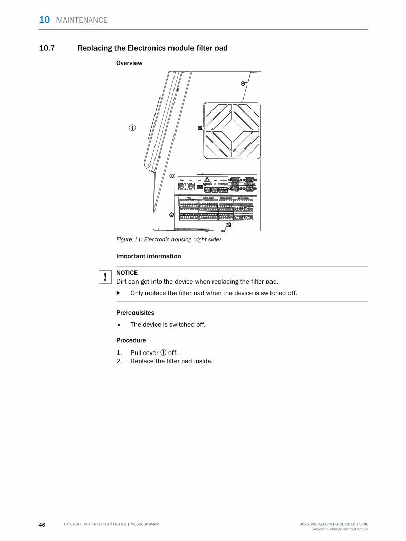
Overview
1
Figure 11: Electronic housing (right side)
Important information
NOTICEDirt can get into the device when replacing the filter pad.
b Only replace the filter pad when the device is switched off.
Prerequisites
• The device is switched off.
Procedure
1. Pull cover 1 off.2. Replace the filter pad inside.
10 MAINTENANCE
46 O P E R A T I N G I N S T R U C T I O N S | MCS200HW-MP 8026608/AE00/V1-0/2021-10 | SICKSubject to change without notice
11 Troubleshooting
11.1 Safety
Requirements for the maintenance personnel
• Only allow an authorized electrician to work on the electrical system or electricalsubassemblies.
• The technician must be familiar with the exhaust gas technology of the operator'splant (hazard by overpressure and toxic and hot flue gases) and be able to avoidhazards when working on gas ducts.
• The technician must be familiar with handling compressed gas cylinders (testgases).
• The technician must be able to avoid hazards caused by noxious test gases.• The technician must be familiar with gas lines and their screw fittings (be able to
ensure gas-tight connections).
11.2 Important information
Sample gases and exhaust gases
CAUTIONRisk of chemical burns by acid gasAcid condensate could escape when working on the sample gas lines and the associ‐ated assemblies.
b Take appropriate protective measures for work (e.g., by wearing a safety mask,protective gloves and acid resistant clothes)
b In case of contact with the eyes, rinse immediately with clear water and consult adoctor.
Electric voltage
NOTICEObserve voltage variantSome spare parts are available in different voltage variants, 115 V or 230 V.The power voltage of your system is shown on the type plate.
b Check spare parts for voltage dependency before fitting:
Please note:
• After working on the gas path: Perform a leak tightness check.• Inlet "P" of valve KK10 in the sample conditioning unit must have a dummy plug.
(The dummy plug is fitted as standard.)• After exchanging assemblies: Put the system back into operation.• After exchanging a span gas cylinder: Parameterize new span gas concentration.
11.3 Error messages and possible causes
Overview
Current pending messages are shown on the device display.
Display of current device state data: Logbook.
The following Table only includes those messages with classification "X" that are impor‐tant for information.
TROUBLESHOOTING 11
8026608/AE00/V1-0/2021-10 | SICK O P E R A T I N G I N S T R U C T I O N S | MCS200HW-MP 47Subject to change without notice
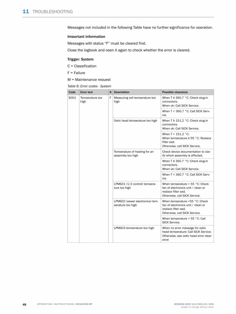
Messages not included in the following Table have no further significance for operation.
Important information
Messages with status “F” must be cleared first.
Close the logbook and open it again to check whether the error is cleared.
Trigger: System
C = Classification
F = Failure
M = Maintenance request
Table 6: Error codes - System
Code Error text K Description Possible clearance
S001 Temperature toohigh
F Measuring cell temperature toohigh
When T ≥ 360.7 °C: Check plug-inconnectors.When ok: Call SICK Service.
When T < 360.7 °C: Call SICK Serv‐ice.
Optic head temperature too high When T ≥ 151.2 °C: Check plug-inconnectors.When ok: Call SICK Service.
When T < 151.2 °C:When temperature ≥ 55 °C: Replacefilter pad.Otherwise, call SICK Service.
Temperature of heating for anassembly too high
Check device documentation to clar‐ify which assembly is affected.
When T ≥ 360.7 °C: Check plug-inconnectors.When ok: Call SICK Service.
When T < 360.7 °C: Call SICK Serv‐ice.
LPMS01 (1/2 control) tempera‐ture too high
When temperature < 55 °C: Checkfan of electronics unit / clean orreplace filter pad.Otherwise, call SICK Service.
LPMS02 (power electronics) tem‐perature too high
When temperature <55 °C: Checkfan of electronics unit / clean orreplace filter pad.Otherwise, call SICK Service.
When temperature < 55 °C: CallSICK Service.
LPMS03 temperature too high When no error message for optichead temperature: Call SICK Service.Otherwise, see optic head error clear‐ance
11 TROUBLESHOOTING
48 O P E R A T I N G I N S T R U C T I O N S | MCS200HW-MP 8026608/AE00/V1-0/2021-10 | SICKSubject to change without notice
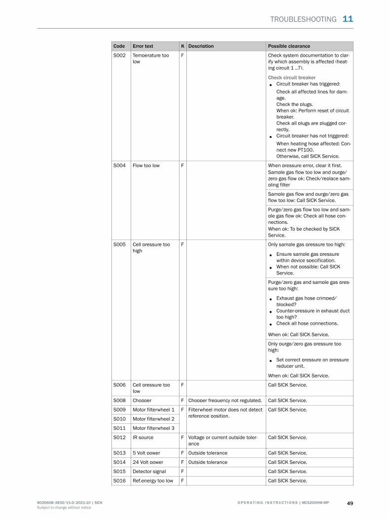
Code Error text K Description Possible clearance
S002 Temperature toolow
F Check system documentation to clar‐ify which assembly is affected (heat‐ing circuit 1 ..7).
Check circuit breaker
• Circuit breaker has triggered:Check all affected lines for dam‐age.Check the plugs.When ok: Perform reset of circuitbreaker.Check all plugs are plugged cor‐rectly.
• Circuit breaker has not triggered:When heating hose affected: Con‐nect new PT100.Otherwise, call SICK Service.
S004 Flow too low F When pressure error, clear it first.Sample gas flow too low and purge/zero gas flow ok: Check/replace sam‐pling filter
Sample gas flow and purge/zero gasflow too low: Call SICK Service.
Purge/zero gas flow too low and sam‐ple gas flow ok: Check all hose con‐nections.When ok: To be checked by SICKService.
S005 Cell pressure toohigh
F Only sample gas pressure too high:
• Ensure sample gas pressurewithin device specification.
• When not possible: Call SICKService.
Purge/zero gas and sample gas pres‐sure too high:
• Exhaust gas hose crimped/blocked?
• Counter-pressure in exhaust ducttoo high?
• Check all hose connections.
When ok: Call SICK Service.
Only purge/zero gas pressure toohigh:
• Set correct pressure on pressurereducer unit.
When ok: Call SICK Service.
S006 Cell pressure toolow
F Call SICK Service.
S008 Chopper F Chopper frequency not regulated. Call SICK Service.
S009 Motor filterwheel 1 F Filterwheel motor does not detectreference position.
Call SICK Service.
S010 Motor filterwheel 2
S011 Motor filterwheel 3
S012 IR source F Voltage or current outside toler‐ance
Call SICK Service.
S013 5 Volt power F Outside tolerance Call SICK Service.
S014 24 Volt power F Outside tolerance Call SICK Service.
S015 Detector signal F Call SICK Service.
S016 Ref.energy too low F Call SICK Service.
TROUBLESHOOTING 11
8026608/AE00/V1-0/2021-10 | SICK O P E R A T I N G I N S T R U C T I O N S | MCS200HW-MP 49Subject to change without notice
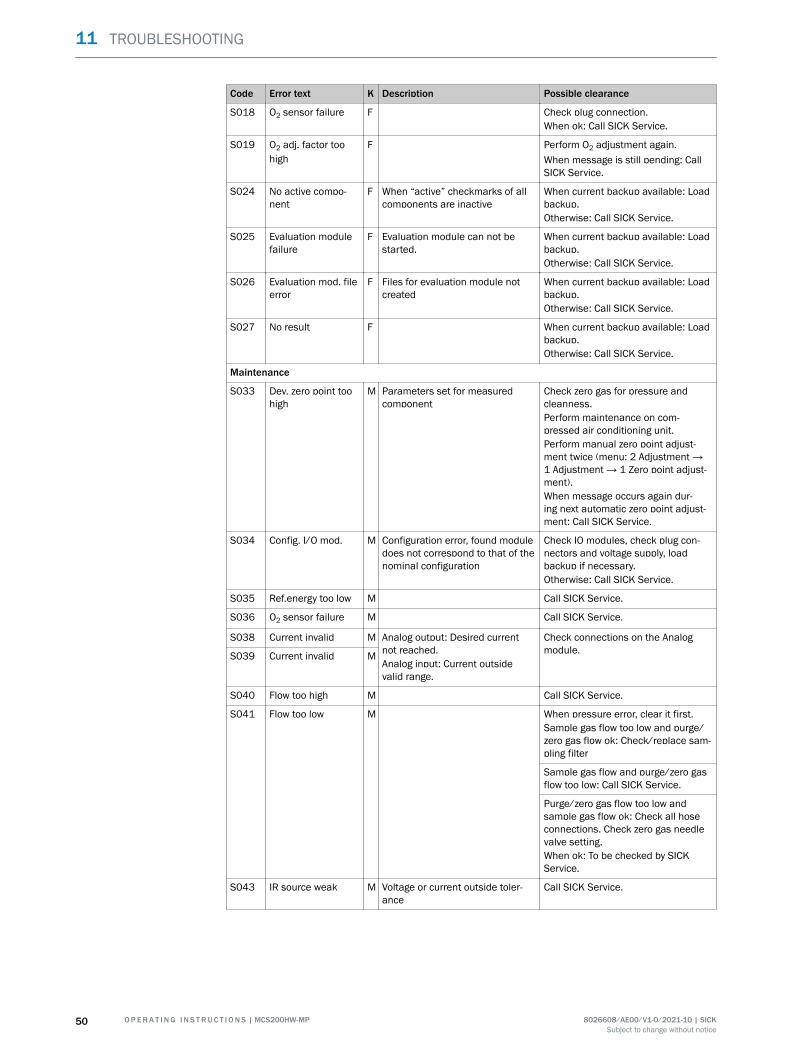
Code Error text K Description Possible clearance
S018 O2 sensor failure F Check plug connection.When ok: Call SICK Service.
S019 O2 adj. factor toohigh
F Perform O2 adjustment again.When message is still pending: CallSICK Service.
S024 No active compo‐nent
F When “active” checkmarks of allcomponents are inactive
When current backup available: Loadbackup.Otherwise: Call SICK Service.
S025 Evaluation modulefailure
F Evaluation module can not bestarted.
When current backup available: Loadbackup.Otherwise: Call SICK Service.
S026 Evaluation mod. fileerror
F Files for evaluation module notcreated
When current backup available: Loadbackup.Otherwise: Call SICK Service.
S027 No result F When current backup available: Loadbackup.Otherwise: Call SICK Service.
Maintenance
S033 Dev. zero point toohigh
M Parameters set for measuredcomponent
Check zero gas for pressure andcleanness.Perform maintenance on com‐pressed air conditioning unit.Perform manual zero point adjust‐ment twice (menu: 2 Adjustment →1 Adjustment → 1 Zero point adjust‐ment).When message occurs again dur‐ing next automatic zero point adjust‐ment: Call SICK Service.
S034 Config. I/O mod. M Configuration error, found moduledoes not correspond to that of thenominal configuration
Check IO modules, check plug con‐nectors and voltage supply, loadbackup if necessary.Otherwise: Call SICK Service.
S035 Ref.energy too low M Call SICK Service.
S036 O2 sensor failure M Call SICK Service.
S038 Current invalid M Analog output: Desired currentnot reached.Analog input: Current outsidevalid range.
Check connections on the Analogmodule.S039 Current invalid M
S040 Flow too high M Call SICK Service.
S041 Flow too low M When pressure error, clear it first.Sample gas flow too low and purge/zero gas flow ok: Check/replace sam‐pling filter
Sample gas flow and purge/zero gasflow too low: Call SICK Service.
Purge/zero gas flow too low andsample gas flow ok: Check all hoseconnections. Check zero gas needlevalve setting.When ok: To be checked by SICKService.
S043 IR source weak M Voltage or current outside toler‐ance
Call SICK Service.
11 TROUBLESHOOTING
50 O P E R A T I N G I N S T R U C T I O N S | MCS200HW-MP 8026608/AE00/V1-0/2021-10 | SICKSubject to change without notice
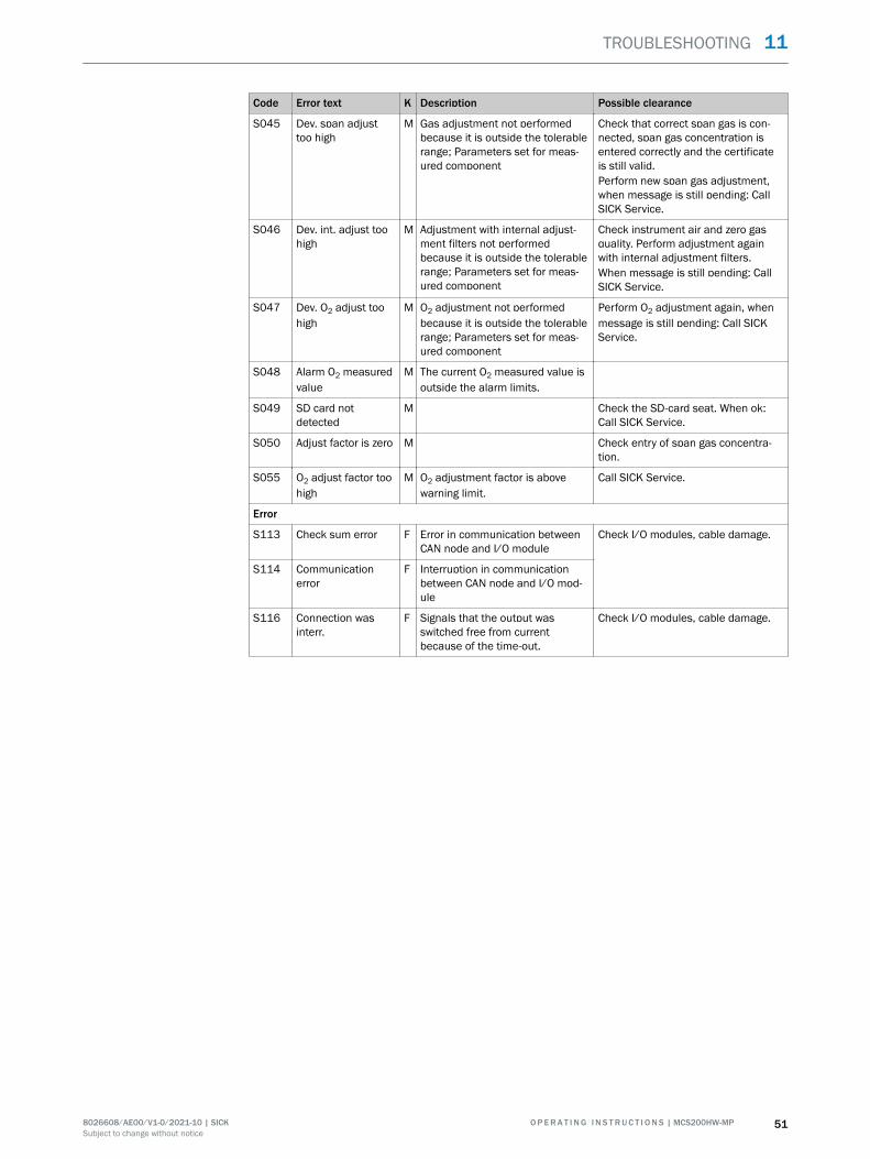
Code Error text K Description Possible clearance
S045 Dev. span adjusttoo high
M Gas adjustment not performedbecause it is outside the tolerablerange; Parameters set for meas‐ured component
Check that correct span gas is con‐nected, span gas concentration isentered correctly and the certificateis still valid.Perform new span gas adjustment,when message is still pending: CallSICK Service.
S046 Dev. int. adjust toohigh
M Adjustment with internal adjust‐ment filters not performedbecause it is outside the tolerablerange; Parameters set for meas‐ured component
Check instrument air and zero gasquality. Perform adjustment againwith internal adjustment filters.When message is still pending: CallSICK Service.
S047 Dev. O2 adjust toohigh
M O2 adjustment not performedbecause it is outside the tolerablerange; Parameters set for meas‐ured component
Perform O2 adjustment again, whenmessage is still pending: Call SICKService.
S048 Alarm O2 measuredvalue
M The current O2 measured value isoutside the alarm limits.
S049 SD card notdetected
M Check the SD-card seat. When ok:Call SICK Service.
S050 Adjust factor is zero M Check entry of span gas concentra‐tion.
S055 O2 adjust factor toohigh
M O2 adjustment factor is abovewarning limit.
Call SICK Service.
Error
S113 Check sum error F Error in communication betweenCAN node and I/O module
Check I/O modules, cable damage.
S114 Communicationerror
F Interruption in communicationbetween CAN node and I/O mod‐ule
S116 Connection wasinterr.
F Signals that the output wasswitched free from currentbecause of the time-out.
Check I/O modules, cable damage.
TROUBLESHOOTING 11
8026608/AE00/V1-0/2021-10 | SICK O P E R A T I N G I N S T R U C T I O N S | MCS200HW-MP 51Subject to change without notice
12 Decommissioning
12.1 Switching off
12.1.1 Switching off
Important information
NOTICERisk of contamination of analyzerThe gas sampling unit and analyzer are flushed with instrument air when the system isnot in measuring operation. When the instrument air is switched off, there is the risk ofcontamination of the analyzer.
• Pull the gas sampling unit out of the exhaust duct when instrument air is notavailable for a longer period of time.
Procedure
1. Switch system off at the external power disconnection unit.2. Purge system with instrument air for a minimum of 10 minutes.3. Switch the calibration gases off.4. Ensure no sample gas reaches the analyzer.
12.1.2 Shutdown
Prerequisites
• System is switched off.
Procedure
1. Ensure the gas sampling unit can not be contaminated (e.g. by pulling the probetube)
2. Switch external instrument air off.3. Close off gas inlets and outlets gas-tight
Related topics
• Switch system off: see "Switching off", page 52
12.2 Return delivery
12.2.1 Shipping for repair
Overview
You can find all information on the repair flat rates, Repair Form (incl. Non-Risk Declara‐tion and return information) at www.sick.com/Reparaturen.
Important information
NOTEWithout the Non-Risk Declaration, the device will either be cleaned by a third-partycompany at the customer's expense or the package will not be accepted.
Procedure
1. Contact your local SICK representative. Addresses: See last page of OperatingInstructions.
12 DECOMMISSIONING
52 O P E R A T I N G I N S T R U C T I O N S | MCS200HW-MP 8026608/AE00/V1-0/2021-10 | SICKSubject to change without notice
2. Clean device.3. Fill in the Repair Form including the Non-Risk Declaration and send it in advance
to the SICK representative by e-mail.4. Pack the unit carefully and shockproof in the original packaging for transport.5. Enclose the Repair Form and attach it to the outside of the packaging.
12.2.2 Cleaning the device before returning
Important information
NOTICEDevice damage through incorrect cleaning.
• Close the housing before cleaning so that no fluid can penetrate.• Do not use a high-pressure cleaner, aggressive mechanical or chemical cleaning
agents.
Prerequisites
• Device is voltage-free.
Procedure
Clean surfaces and parts with media contact1. Remove loose contamination with compressed air.2. Remove adhering contamination with a mild soap solution and a soft cloth.3. Do not clean optical surfaces.
12.3 Transport
Procedure
1. Protect the device before transport.2. Use the original packaging for transport or alternatively a suitable padded stable
packaging.A transport container with adequate stability can also be used.
3. Protect the device with padding from shocks and vibrations.4. Thoroughly secure the device in place inside the transport container. Make sure
there is sufficient space between the analyzer and the walls of the transportcontainer.
12.4 Disposal
Important information
NOTEThe following subassemblies contain substances that may have to be disposed ofseparately:
• Electronics: Capacitors, rechargeable batteries, batteries.• Display: Liquid of LC display.• Sample gas filter: Could be be contaminated with pollutants.• All lines with sample gas contact could be contaminated with pollutants.
Disposal of the device
The device can easily be disassembled into its components which can then be sent tothe respective raw material recycling facilities.
DECOMMISSIONING 12
8026608/AE00/V1-0/2021-10 | SICK O P E R A T I N G I N S T R U C T I O N S | MCS200HW-MP 53Subject to change without notice
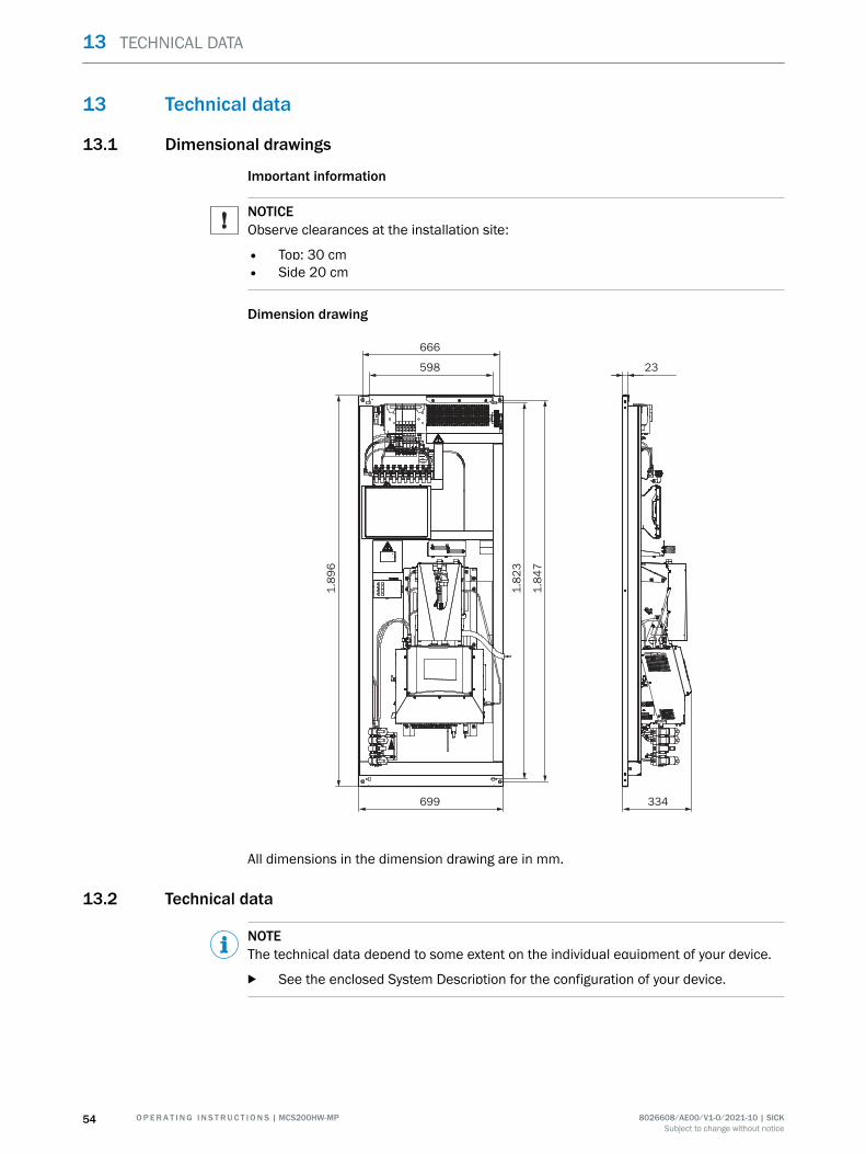
13 Technical data
13.1 Dimensional drawings
Important information
NOTICEObserve clearances at the installation site:
• Top: 30 cm• Side 20 cm
Dimension drawing
699
1.8
96
23
1.8
47
1.8
23
598
666
334
All dimensions in the dimension drawing are in mm.
13.2 Technical data
NOTEThe technical data depend to some extent on the individual equipment of your device.
b See the enclosed System Description for the configuration of your device.
13 TECHNICAL DATA
54 O P E R A T I N G I N S T R U C T I O N S | MCS200HW-MP 8026608/AE00/V1-0/2021-10 | SICKSubject to change without notice
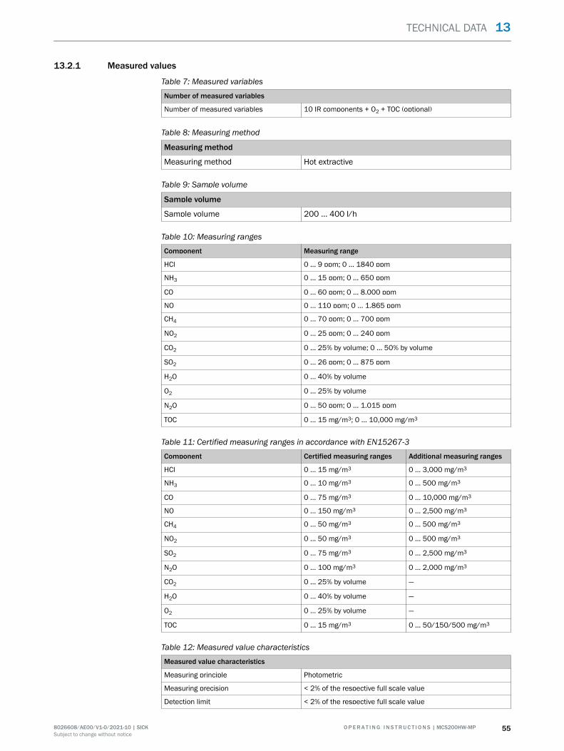
13.2.1 Measured values
Table 7: Measured variables
Number of measured variables
Number of measured variables 10 IR components + O2 + TOC (optional)
Table 8: Measuring method
Measuring method
Measuring method Hot extractive
Table 9: Sample volume
Sample volume
Sample volume 200 ... 400 l/h
Table 10: Measuring ranges
Component Measuring range
HCl 0 ... 9 ppm; 0 ... 1840 ppm
NH3 0 ... 15 ppm; 0 ... 650 ppm
CO 0 ... 60 ppm; 0 ... 8.000 ppm
NO 0 ... 110 ppm; 0 ... 1.865 ppm
CH4 0 ... 70 ppm; 0 ... 700 ppm
NO2 0 ... 25 ppm; 0 ... 240 ppm
CO2 0 ... 25% by volume; 0 ... 50% by volume
SO2 0 ... 26 ppm; 0 ... 875 ppm
H2O 0 ... 40% by volume
O2 0 ... 25% by volume
N2O 0 ... 50 ppm; 0 ... 1.015 ppm
TOC 0 ... 15 mg/m3; 0 ... 10,000 mg/m3
Table 11: Certified measuring ranges in accordance with EN15267-3
Component Certified measuring ranges Additional measuring ranges
HCl 0 ... 15 mg/m3 0 ... 3,000 mg/m3
NH3 0 ... 10 mg/m3 0 ... 500 mg/m3
CO 0 ... 75 mg/m3 0 ... 10,000 mg/m3
NO 0 ... 150 mg/m3 0 ... 2,500 mg/m3
CH4 0 ... 50 mg/m3 0 ... 500 mg/m3
NO2 0 ... 50 mg/m3 0 ... 500 mg/m3
SO2 0 ... 75 mg/m3 0 ... 2,500 mg/m3
N2O 0 ... 100 mg/m3 0 ... 2,000 mg/m3
CO2 0 ... 25% by volume —
H2O 0 ... 40% by volume —
O2 0 ... 25% by volume —
TOC 0 ... 15 mg/m3 0 ... 50/150/500 mg/m3
Table 12: Measured value characteristics
Measured value characteristics
Measuring principle Photometric
Measuring precision < 2% of the respective full scale value
Detection limit < 2% of the respective full scale value
TECHNICAL DATA 13
8026608/AE00/V1-0/2021-10 | SICK O P E R A T I N G I N S T R U C T I O N S | MCS200HW-MP 55Subject to change without notice
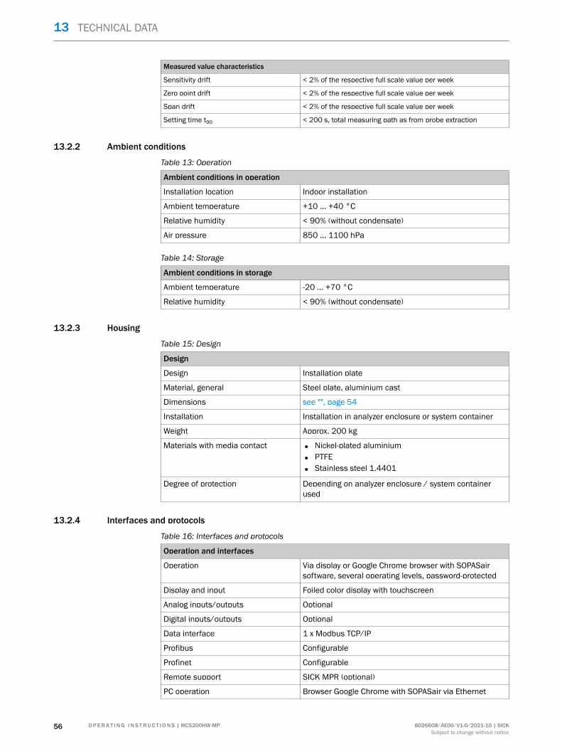
Measured value characteristics
Sensitivity drift < 2% of the respective full scale value per week
Zero point drift < 2% of the respective full scale value per week
Span drift < 2% of the respective full scale value per week
Setting time t90 < 200 s, total measuring path as from probe extraction
13.2.2 Ambient conditions
Table 13: Operation
Ambient conditions in operation
Installation location Indoor installation
Ambient temperature +10 ... +40 °C
Relative humidity < 90% (without condensate)
Air pressure 850 ... 1100 hPa
Table 14: Storage
Ambient conditions in storage
Ambient temperature -20 ... +70 °C
Relative humidity < 90% (without condensate)
13.2.3 Housing
Table 15: Design
Design
Design Installation plate
Material, general Steel plate, aluminium cast
Dimensions see "", page 54
Installation Installation in analyzer enclosure or system container
Weight Approx. 200 kg
Materials with media contact • Nickel-plated aluminium
• PTFE
• Stainless steel 1.4401
Degree of protection Depending on analyzer enclosure / system containerused
13.2.4 Interfaces and protocols
Table 16: Interfaces and protocols
Operation and interfaces
Operation Via display or Google Chrome browser with SOPASairsoftware, several operating levels, password-protected
Display and input Foiled color display with touchscreen
Analog inputs/outputs Optional
Digital inputs/outputs Optional
Data interface 1 x Modbus TCP/IP
Profibus Configurable
Profinet Configurable
Remote support SICK MPR (optional)
PC operation Browser Google Chrome with SOPASair via Ethernet
13 TECHNICAL DATA
56 O P E R A T I N G I N S T R U C T I O N S | MCS200HW-MP 8026608/AE00/V1-0/2021-10 | SICKSubject to change without notice
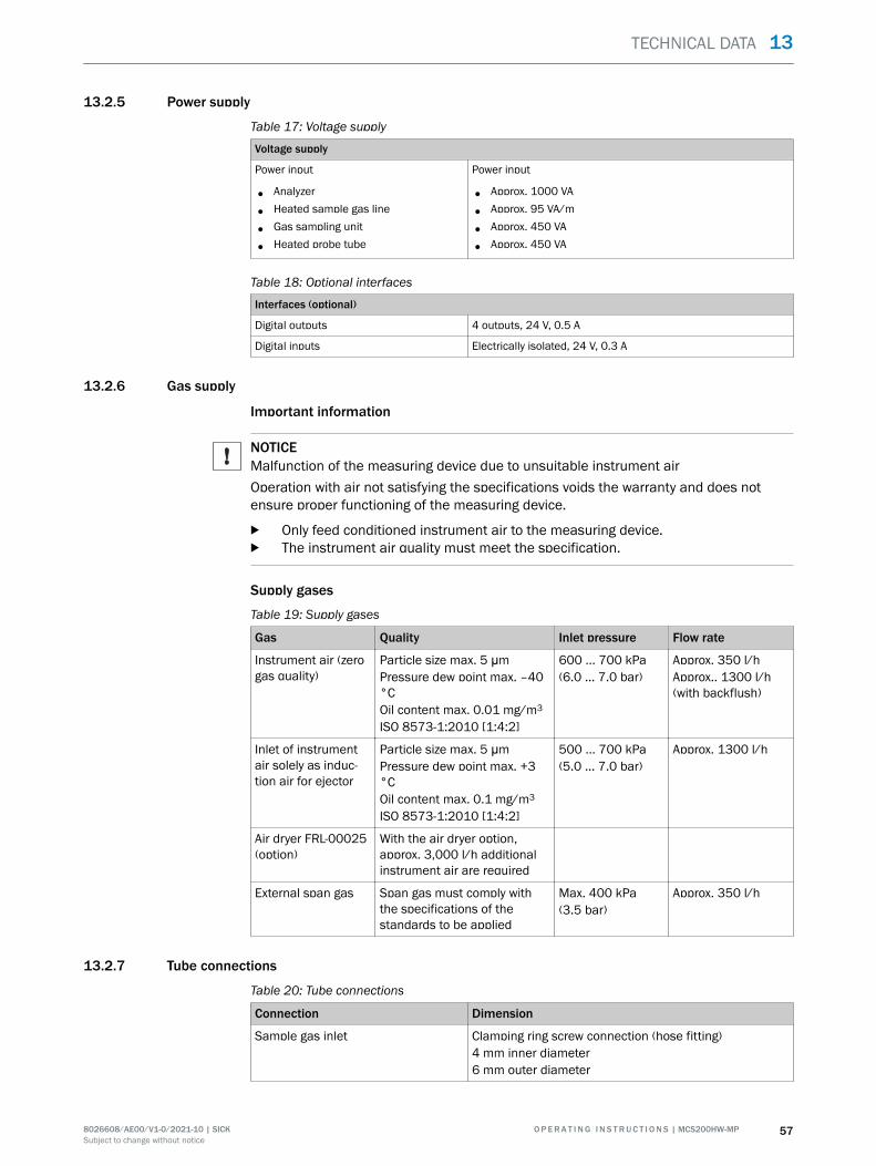
13.2.5 Power supply
Table 17: Voltage supply
Voltage supply
Power input
• Analyzer
• Heated sample gas line
• Gas sampling unit
• Heated probe tube
Power input
• Approx. 1000 VA
• Approx. 95 VA/m
• Approx. 450 VA
• Approx. 450 VA
Table 18: Optional interfaces
Interfaces (optional)
Digital outputs 4 outputs, 24 V, 0.5 A
Digital inputs Electrically isolated, 24 V, 0.3 A
13.2.6 Gas supply
Important information
NOTICEMalfunction of the measuring device due to unsuitable instrument airOperation with air not satisfying the specifications voids the warranty and does notensure proper functioning of the measuring device.
b Only feed conditioned instrument air to the measuring device.b The instrument air quality must meet the specification.
Supply gases
Table 19: Supply gases
Gas Quality Inlet pressure Flow rate
Instrument air (zerogas quality)
Particle size max. 5 μmPressure dew point max. –40°COil content max. 0.01 mg/m3
ISO 8573-1:2010 [1:4:2]
600 ... 700 kPa(6.0 ... 7.0 bar)
Approx. 350 l/hApprox.. 1300 l/h(with backflush)
Inlet of instrumentair solely as induc‐tion air for ejector
Particle size max. 5 μmPressure dew point max. +3°COil content max. 0.1 mg/m3
ISO 8573-1:2010 [1:4:2]
500 ... 700 kPa(5.0 ... 7.0 bar)
Approx. 1300 l/h
Air dryer FRL-00025(option)
With the air dryer option,approx. 3,000 l/h additionalinstrument air are required
External span gas Span gas must comply withthe specifications of thestandards to be applied
Max. 400 kPa(3.5 bar)
Approx. 350 l/h
13.2.7 Tube connections
Table 20: Tube connections
Connection Dimension
Sample gas inlet Clamping ring screw connection (hose fitting)4 mm inner diameter6 mm outer diameter
TECHNICAL DATA 13
8026608/AE00/V1-0/2021-10 | SICK O P E R A T I N G I N S T R U C T I O N S | MCS200HW-MP 57Subject to change without notice
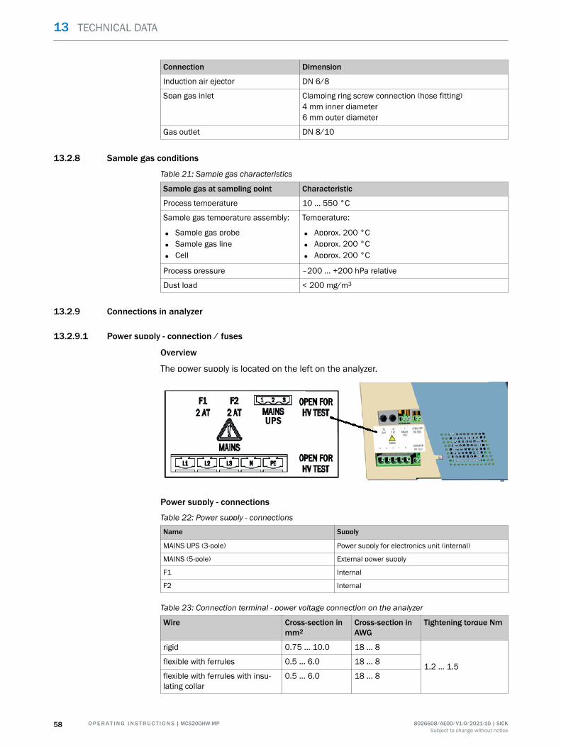
Connection Dimension
Induction air ejector DN 6/8
Span gas inlet Clamping ring screw connection (hose fitting)4 mm inner diameter6 mm outer diameter
Gas outlet DN 8/10
13.2.8 Sample gas conditions
Table 21: Sample gas characteristics
Sample gas at sampling point Characteristic
Process temperature 10 ... 550 °C
Sample gas temperature assembly:
• Sample gas probe
• Sample gas line
• Cell
Temperature:
• Approx. 200 °C
• Approx. 200 °C
• Approx. 200 °C
Process pressure –200 ... +200 hPa relative
Dust load < 200 mg/m3
13.2.9 Connections in analyzer
13.2.9.1 Power supply - connection / fuses
Overview
The power supply is located on the left on the analyzer.
UPS
Power supply - connections
Table 22: Power supply - connections
Name Supply
MAINS UPS (3-pole) Power supply for electronics unit (internal)
MAINS (5-pole) External power supply
F1 Internal
F2 Internal
Table 23: Connection terminal - power voltage connection on the analyzer
Wire Cross-section inmm2
Cross-section inAWG
Tightening torque Nm
rigid 0.75 ... 10.0 18 ... 8
1.2 ... 1.5flexible with ferrules 0.5 ... 6.0 18 ... 8
flexible with ferrules with insu‐lating collar
0.5 ... 6.0 18 ... 8
13 TECHNICAL DATA
58 O P E R A T I N G I N S T R U C T I O N S | MCS200HW-MP 8026608/AE00/V1-0/2021-10 | SICKSubject to change without notice
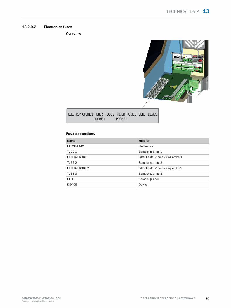
13.2.9.2 Electronics fuses
Overview
ELECTRONIC FILTERTUBE 1 FILTER
PROBE 2PROBE 1
TUBE 2 TUBE 3 CELL DEVICE
Fuse connections
Name Fuse for
ELECTRONIC Electronics
TUBE 1 Sample gas line 1
FILTER/PROBE 1 Filter heater / measuring probe 1
TUBE 2 Sample gas line 2
FILTER/PROBE 2 Filter heater / measuring probe 2
TUBE 3 Sample gas line 3
CELL Sample gas cell
DEVICE Device
TECHNICAL DATA 13
8026608/AE00/V1-0/2021-10 | SICK O P E R A T I N G I N S T R U C T I O N S | MCS200HW-MP 59Subject to change without notice
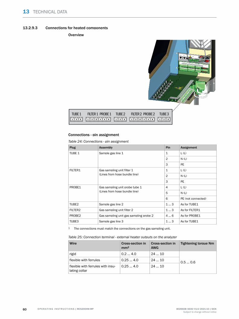
13.2.9.3 Connections for heated components
Overview
TUBE 1 FILTER 1 PROBE 1 FILTER 2 PROBE 2TUBE 2 TUBE 3
Connections - pin assignment
Table 24: Connections - pin assignment
Plug Assembly Pin Assignment
TUBE 1 Sample gas line 1 1 L (L)
2 N (L)
3 PE
FILTER1 Gas sampling unit filter 1(Lines from hose bundle line)
1 L (L)
2 N (L)
3 PE
PROBE1 Gas sampling unit probe tube 1(Lines from hose bundle line)
4 L (L)
5 N (L)
6 PE (not connected)
TUBE2 Sample gas line 2 1 ... 3 As for TUBE1
FILTER2 Gas sampling unit filter 2 1 ... 3 As for FILTER1
PROBE2 Gas sampling unit gas sampling probe 2 4 ... 6 As for PROBE1
TUBE3 Sample gas line 3 1 ... 3 As for TUBE1
1 The connections must match the connections on the gas sampling unit.
Table 25: Connection terminal - external heater outputs on the analyzer
Wire Cross-section inmm2
Cross-section inAWG
Tightening torque Nm
rigid 0.2 ... 4.0 24 ... 10
0.5 ... 0.6flexible with ferrules 0.25 ... 4.0 24 ... 10
flexible with ferrules with insu‐lating collar
0.25 ... 4.0 24 ... 10
13 TECHNICAL DATA
60 O P E R A T I N G I N S T R U C T I O N S | MCS200HW-MP 8026608/AE00/V1-0/2021-10 | SICKSubject to change without notice
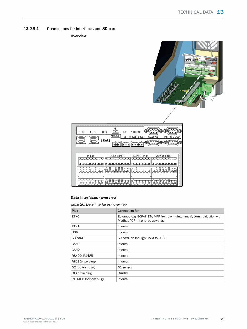
13.2.9.4 Connections for interfaces and SD card
Overview
ETHO ETH1 USB CAN PROFIBUS
1 2 RS422/RS485 RS232 02 DISP.
PT100 DIGITAL INPUTS DIGITAL OUTPUTS VALVE OUTPUTS
I/0-MOD.
Data interfaces - overview
Table 26: Data interfaces - overview
Plug Connection for
ETH0 Ethernet (e.g. SOPAS ET), MPR (remote maintenance), communication viaModbus TCP - line is led upwards
ETH1 Internal
USB Internal
SD card SD card (on the right, next to USB)
CAN1 Internal
CAN2 Internal
RS422, RS485 Internal
RS232 (top plug) Internal
O2 (bottom plug) O2 sensor
DISP (top plug) Display
I/O-MOD (bottom plug) Internal
TECHNICAL DATA 13
8026608/AE00/V1-0/2021-10 | SICK O P E R A T I N G I N S T R U C T I O N S | MCS200HW-MP 61Subject to change without notice
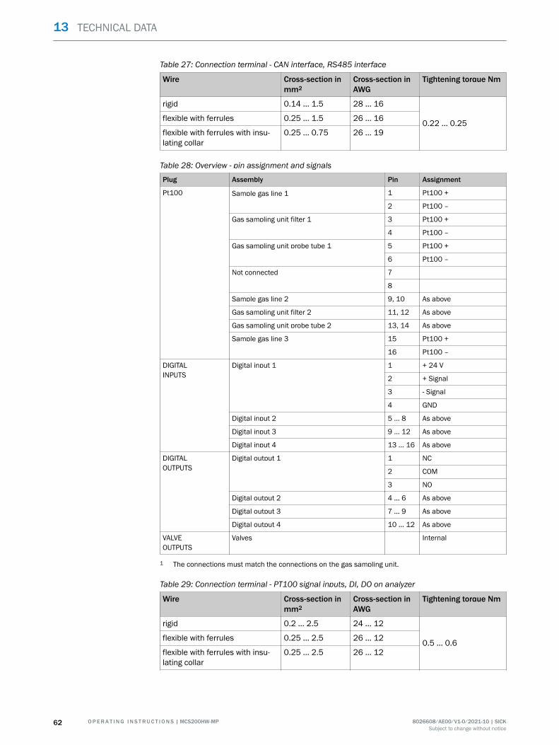
Table 27: Connection terminal - CAN interface, RS485 interface
Wire Cross-section inmm2
Cross-section inAWG
Tightening torque Nm
rigid 0.14 ... 1.5 28 ... 16
0.22 ... 0.25flexible with ferrules 0.25 ... 1.5 26 ... 16
flexible with ferrules with insu‐lating collar
0.25 ... 0.75 26 ... 19
Table 28: Overview - pin assignment and signals
Plug Assembly Pin Assignment
Pt100 Sample gas line 1 1 Pt100 +
2 Pt100 –
Gas sampling unit filter 1 3 Pt100 +
4 Pt100 –
Gas sampling unit probe tube 1 5 Pt100 +
6 Pt100 –
Not connected 7
8
Sample gas line 2 9, 10 As above
Gas sampling unit filter 2 11, 12 As above
Gas sampling unit probe tube 2 13, 14 As above
Sample gas line 3 15 Pt100 +
16 Pt100 –
DIGITALINPUTS
Digital input 1 1 + 24 V
2 + Signal
3 - Signal
4 GND
Digital input 2 5 ... 8 As above
Digital input 3 9 ... 12 As above
Digital input 4 13 ... 16 As above
DIGITALOUTPUTS
Digital output 1 1 NC
2 COM
3 NO
Digital output 2 4 ... 6 As above
Digital output 3 7 ... 9 As above
Digital output 4 10 ... 12 As above
VALVEOUTPUTS
Valves Internal
1 The connections must match the connections on the gas sampling unit.
Table 29: Connection terminal - PT100 signal inputs, DI, DO on analyzer
Wire Cross-section inmm2
Cross-section inAWG
Tightening torque Nm
rigid 0.2 ... 2.5 24 ... 12
0.5 ... 0.6flexible with ferrules 0.25 ... 2.5 26 ... 12
flexible with ferrules with insu‐lating collar
0.25 ... 2.5 26 ... 12
13 TECHNICAL DATA
62 O P E R A T I N G I N S T R U C T I O N S | MCS200HW-MP 8026608/AE00/V1-0/2021-10 | SICKSubject to change without notice
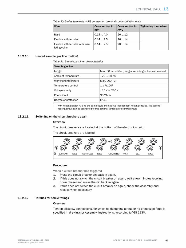
Table 30: Series terminals - UPS connection terminals on installation plate
Wire Cross section inmm2
Cross section inAWG
Tightening torque Nm
Rigid 0.14 ... 4.0 26 ... 12
-Flexible with ferrules 0.14 ... 2.5 26 ... 14
Flexible with ferrules with insu‐lating collar
0.14 ... 2.5 26 ... 14
13.2.10 Heated sample gas line (option)
Table 31: Sample gas line - characteristics
Sample gas line
Length Max. 50 m certified, longer sample gas lines on request
Ambient temperature –20 ... 80 °C
Working temperature Max. 200 °C
Temperature control 1 x Pt1001
Voltage supply 115 V or 230 V
Power input 90 VA/m
Degree of protection IP 43
1 With heating length >35 m, the sample gas line has two independent heating circuits. The secondheating circuit can be connected to this optional temperature control circuit.
13.2.11 Switching on the circuit breakers again
Overview
The circuit breakers are located at the bottom of the electronics unit.
The circuit breakers are labeled.
TUBE 1ELECTRONIC FILTER / PROBE 1 FILTER / PROBE 2 TUBE 3 CELLTUBE 2 DEVICE
Procedure
When a circuit breaker has triggered1. Press the circuit breaker pin back in again.2. If this does not switch the circuit breaker on again, wait a few minutes (cooling
down phase) and press the pin back in again.3. If this does not switch the circuit breaker on again, check the assembly and
replace when necessary.
13.2.12 Torques for screw fittings
Overview
Tighten all screw connections, for which no tightening torque or no pretension force isspecified in drawings or Assembly Instructions, according to VDI 2230.
TECHNICAL DATA 13
8026608/AE00/V1-0/2021-10 | SICK O P E R A T I N G I N S T R U C T I O N S | MCS200HW-MP 63Subject to change without notice
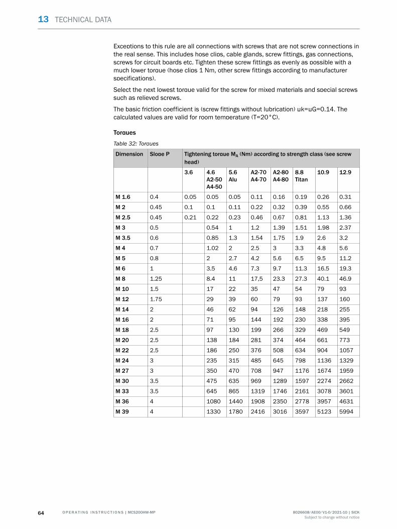
Exceptions to this rule are all connections with screws that are not screw connections inthe real sense. This includes hose clips, cable glands, screw fittings, gas connections,screws for circuit boards etc. Tighten these screw fittings as evenly as possible with amuch lower torque (hose clips 1 Nm, other screw fittings according to manufacturerspecifications).
Select the next lowest torque valid for the screw for mixed materials and special screwssuch as relieved screws.
The basic friction coefficient is (screw fittings without lubrication) µk=µG=0.14. Thecalculated values are valid for room temperature (T=20°C).
Torques
Table 32: Torques
Dimension Slope P Tightening torque MA (Nm) according to strength class (see screwhead)
3.6 4.6A2-50A4-50
5.6Alu
A2-70A4-70
A2-80A4-80
8.8Titan
10.9 12.9
M 1.6 0.4 0.05 0.05 0.05 0.11 0.16 0.19 0.26 0.31
M 2 0.45 0.1 0.1 0.11 0.22 0.32 0.39 0.55 0.66
M 2.5 0.45 0.21 0.22 0.23 0.46 0.67 0.81 1.13 1.36
M 3 0.5 0.54 1 1.2 1.39 1.51 1.98 2.37
M 3.5 0.6 0.85 1.3 1.54 1.75 1.9 2.6 3.2
M 4 0.7 1.02 2 2.5 3 3.3 4.8 5.6
M 5 0.8 2 2.7 4.2 5.6 6.5 9.5 11.2
M 6 1 3.5 4.6 7.3 9.7 11.3 16.5 19.3
M 8 1.25 8.4 11 17,5 23.3 27.3 40.1 46.9
M 10 1.5 17 22 35 47 54 79 93
M 12 1.75 29 39 60 79 93 137 160
M 14 2 46 62 94 126 148 218 255
M 16 2 71 95 144 192 230 338 395
M 18 2.5 97 130 199 266 329 469 549
M 20 2.5 138 184 281 374 464 661 773
M 22 2.5 186 250 376 508 634 904 1057
M 24 3 235 315 485 645 798 1136 1329
M 27 3 350 470 708 947 1176 1674 1959
M 30 3.5 475 635 969 1289 1597 2274 2662
M 33 3.5 645 865 1319 1746 2161 3078 3601
M 36 4 1080 1440 1908 2350 2778 3957 4631
M 39 4 1330 1780 2416 3016 3597 5123 5994
13 TECHNICAL DATA
64 O P E R A T I N G I N S T R U C T I O N S | MCS200HW-MP 8026608/AE00/V1-0/2021-10 | SICKSubject to change without notice
14 Annex
14.1 Conformities
Conformities• EC Directive: LVD (Low Voltage Directive)
EN 61010-1: Safety requirements for electrical equipment for measurement, con‐trol and laboratory use
• EC Directive: EMC (Electromagnetic Compatibility)EN 61326: Electrical equipment for measurement, control and laboratory use,EMC requirements
Further standards and directives: See Declaration of Conformity provided with thedevice.
14.2 Licenses
14.2.1 Liability disclaimer
The firmware for this device has been developed using Open Source Software. Anychanges to the Open-Source components are in the general responsibility of the user.All warranty claims are excluded in this case.
The following exclusion of liability applies to the GPL components in relation to therights holders: This program is distributed in the hope that it will be of use, but with noguarantee of this; neither is there any implied guarantee of marketability or suitabilityfor a particular purpose. Refer to the GNU General Public License for details.
With regard to the other Open-Source components, we refer to the liability disclaimersof the copyright holders in the licence texts on the CD delivered.
14.2.2 Software licences
In this product, SICK uses unchanged and, as far is necessary and in compliance withrelevant licence conditions, changed Open Source Software.
The firmware of this device is therefore subject to the copyrights listed on the CDdelivered. Please refer to the storage medium delivered for a complete list of the OpenSource programs used as well as the relevant licence conditions.
14.2.3 Source codes
The source codes for the Open Source programs used in this device can be requestedusing the following email address: Please enter “Open Source Software” as subject.
ANNEX 14
8026608/AE00/V1-0/2021-10 | SICK O P E R A T I N G I N S T R U C T I O N S | MCS200HW-MP 65Subject to change without notice
Detailed addresses and further locations at www.sick.com
Australia Phone +61 (3) 9457 0600 1800 33 48 02 – tollfree E-Mail [email protected] Phone +43 (0) 2236 62288-0 E-Mail [email protected]/Luxembourg Phone +32 (0) 2 466 55 66 E-Mail [email protected] Phone +55 11 3215-4900 E-Mail [email protected] Phone +1 905.771.1444 E-Mail [email protected] Republic Phone +420 234 719 500 E-Mail [email protected] Phone +56 (2) 2274 7430 E-Mail [email protected] Phone +86 20 2882 3600 E-Mail [email protected] Phone +45 45 82 64 00 E-Mail [email protected] Phone +358-9-25 15 800 E-Mail [email protected] Phone +33 1 64 62 35 00 E-Mail [email protected] Phone +49 (0) 2 11 53 010 E-Mail [email protected] Phone +30 210 6825100 E-Mail [email protected] Kong Phone +852 2153 6300 E-Mail [email protected]
Hungary Phone +36 1 371 2680 E-Mail [email protected] Phone +91-22-6119 8900 E-Mail [email protected] Phone +972 97110 11 E-Mail [email protected] Phone +39 02 27 43 41 E-Mail [email protected] Phone +81 3 5309 2112 E-Mail [email protected] Phone +603-8080 7425 E-Mail [email protected] Phone +52 (472) 748 9451 E-Mail [email protected] Phone +31 (0) 30 229 25 44 E-Mail [email protected] Zealand Phone +64 9 415 0459 0800 222 278 – tollfree E-Mail [email protected] Phone +47 67 81 50 00 E-Mail [email protected] Phone +48 22 539 41 00 E-Mail [email protected] Phone +40 356-17 11 20 E-Mail [email protected] Phone +7 495 283 09 90 E-Mail [email protected] Phone +65 6744 3732 E-Mail [email protected]
Slovakia Phone +421 482 901 201 E-Mail [email protected] Phone +386 591 78849 E-Mail [email protected] Africa Phone +27 10 060 0550 E-Mail [email protected] Korea Phone +82 2 786 6321/4 E-Mail [email protected] Spain Phone +34 93 480 31 00 E-Mail [email protected] Phone +46 10 110 10 00 E-Mail [email protected] Phone +41 41 619 29 39 E-Mail [email protected] Phone +886-2-2375-6288 E-Mail [email protected] Phone +66 2 645 0009 E-Mail [email protected] Phone +90 (216) 528 50 00 E-Mail [email protected] Arab Emirates Phone +971 (0) 4 88 65 878 E-Mail [email protected] Kingdom Phone +44 (0)17278 31121 E-Mail [email protected] Phone +1 800.325.7425 E-Mail [email protected] Phone +65 6744 3732 E-Mail [email protected]
SICK AG | Waldkirch | Germany | www.sick.com
8026
608/
AE00
/V1-
0/20
21-1
0/en