multilift - mecano · 2016-03-03 · 32 lifting columns type multilift multilift s design slim...
TRANSCRIPT

MultiliftTwo-stage lifting column

30 Lifting columns
Two-stage lifting column - Multilift
Features: � Quadruple bearings with POM slide bearing shells
�High-performance DC motor
� Integrated limit switches
� Self-locking, even under max. load
Slimline design and and an unbeatable price/performance ratio
Options: � Version with manual drive via crank handle
� Special stroke lengths
� Quadro control enables control of up to 32 columns synchron
� Tested to EN 60601-1 3E
High-performance DC motor
9 Single or synchronous control supported
Longitudinal slots 9Simple connection
Milled slot in the external profile (version B)
9 This enables the bracing of two parallel Multilifts
Version A, without milled slot
Version B, with milled slot in the external profile
with interior carriage

31Lifting columns
Intr
od
uct
ion
Lift
ing
co
lum
ns
Elec
tric
cyl
ind
erC
on
tro
ls &
Acc
esso
ries
Ap
pen
dix
Are
as o
f ap
plic
atio
nProperties / Technical data
Versions(Dimensions, order numbers)
Accessories
� General information/operating conditions Page 32
� Power diagram ......................................... Page 32
� Load data .................................................. Page 32
� Multilift Mono und Synchro .................... Page 34
� Multilift with internal carriage Mono und Synchro ................................... Page 36
� Multilift Synchronous package ............... Page 38
� Adaptor bar .............................................. Page 39
� Assembly plate ......................................... Page 40
� RK SyncFlex ............................................... Page 41
� Foot ........................................................... Page 42
� Controls .................................................... Page 44
� PLC/PC data interface ............................... Page 45
� Hand switches .......................................... Page 45
Fixing
Position determination
1 or 2
Multilift - Table of contents

32 Lifting columns
Type Multilift Multilift S
Design Slim lifting column
Guide Quadruple bearings with POM slide bearing shells
Installation position Any position / suspended with drop protection provided by the customer
Push force* 3,000 N 1,000 N
Pull force* 1,000 N (only in conjunction with factory-mounted base plate)
Max. speed 8 mm/s 16 mm/s
Voltage 24 V DC
Power input 120 W
Protection class IP 20 / IP10 for version B (with milled slot)
Self-locking 3,000 N 1,000 N
Ambient temperature +5°C to +40°C
Displacement during synchronous operation 0-2 mm 0-4 mm
Duty cycle At nominal load, 10% (max. 2 mins operating time, 18 mins rest time)
Multilift – Technical data
Current output/Force diagram
General information/operating conditions
Multilift 1,000N at 24V*1Multilift 3,000N at 24V*1Multilift 1,000N at 36V*2Multilift 3,000N at 36V*2
Load dataMx= 150 Nm(dynamic)
Fpull= 1,000/3,000 N
Fpush= 1,000 N
My= 100 Nm(dynamic)
Support torque300 Nm (static)
Support torque200 Nm (static)
* In medical applications, the maximum pull force of 500 N and, in the case of the version with a travel speed of 8 mm/s, the maximum push force of 2,000 N must not be exceeded.
Speed/Force diagram
0
5
10
15
20
25
0 500 1000 1500 2000 2500 3000
V [
mm
/s]
Last [N]
Multilift 1000N bei 24VMultilift 3000N bei 24V
Multilift 1000N bei 36VMultilift 3000N bei 36V
Geschwindigkeits - KraftdiagrammMultilift
Multilift 1,000N at 24V*1Multilift 3,000N at 24V*1Multilift 1,000N at 36V*2Multilift 3,000N at 36V*2
Load [N]
Stromaufnahme - KraftdiagrammMultilift
0
0,5
1
1,5
2
2,5
3
3,5
4
4,5
5
0 500 1000 1500 2000 2500 3000
I [A
]
Last [N]
Multilift 1000N bei 24VMultilift 3000N bei 24V
Multilift 1000N bei 36VMultilift 3000N bei 36V
Load [N]24 V*1 determined with a transformer control 120 VA36 V*2 determined with a MultiControl duo

33Lifting columns
Intr
od
uct
ion
Lift
ing
co
lum
ns
Elec
tric
cyl
ind
erC
on
tro
ls &
Acc
esso
ries
Ap
pen
dix
Are
as o
f ap
plic
atio
n
=
Parallel operation
The standard version also supports parallel opera-tion of two Multilifts (no synchronisation). This may produce different lifting positions during operation, which can be levelled out by moving to the end posi-tions.
Synchronous operation
Synchronous operation of two or more columns. In conjunction with the integrated sensors, the control (see page 44) ensures synchronisation, and thus constant alignment of all the columns in both direc-tions of travel, even if subject to different loads. The synchronous operation tolerance depends on the lift-ing speed and is max 2 mm on the 8 mm/s version and max 4 mm on the 16 mm/s version.A memory function is also available.
=/
Multilift Mono Multilift Synchro
1-2 Multilifts in single or parallel operation 2-4 Multilifts in synchronous operation
Height-adjustable assembly workplaces
Universal Table Ironing Machine

34 Lifting columns
Multilift - Versions
Inst
alla
tio
n h
eig
ht
wit
ho
ut
bas
e p
late
(H
)
Inst
alla
tio
n h
eig
ht
wit
h b
ase
pla
te I
; K; M
(p
ull)
+ 8
mm
Inst
alla
tio
n h
eig
ht-
40
mm
Inst
alla
tio
n h
eig
ht
- 10
mm
BLOCAN®- 40 slot geometry M8 / 40 deep
View “A”
Lateral receptacle output with synchro-nous control (cable length 2.5 m)
Helix cable Length 0.5-1.2 m
Counterbore Counterbore
Version A without milled slot in the exter-nal profile
Version B with milled slot in the external profile
Base plate ( I ) withfixing plates(4 counterbores)
Base plate ( M )flush
Base plate ( K ) withfixing plates(2 counterbores)

35Lifting columns
Intr
od
uct
ion
Lift
ing
co
lum
ns
Elec
tric
cyl
ind
erC
on
tro
ls &
Acc
esso
ries
Ap
pen
dix
Are
as o
f ap
plic
atio
n
Multilift Mono
Code No. Typemax.
push force [N]max.
pull force [N]Total travel
[mm]
Installation height without base plate [mm]
Weight [kg]
QAB13_G0_0355 Multilift 350
3,000 / 2,000 (med.)
1,000 / 500 (med.)
355 550 9.1
QAB13_G0_0400 Multilift 400 400 595 10.0
QAB13_G0_0450 Multilift 450 452 650 10.8
QAB13_G0_0500 Multilift 500 498 695 11.5
QAB26_G0_0355 Multilift 350 s
1,000 / 1,000 (med.)
1,000 / 500 (med.)
355 550 9.1
QAB26_G0_0400 Multilift 400 s 400 595 10.0
QAB26_G0_0450 Multilift 450 s 452 650 10.8
QAB26_G0_0500 Multilift 500 s 498 695 11.5
Version:1 = B (with milled slot in the external profile)2 = A (without milled slot in the external profile)
Base plate withFixing plates
Base plate flush8 mm
Multilift – Versions
Code No. Typemax.
push force [N]max.
pull force [N]Total travel
[mm]
Installation height incl. base
plate [mm]Weight [kg]
QAB13_G0_0355 Multilift 350
3,000 / 2,000 (med.)
1,000 / 500 (med.)
355 558 10.1
QAB13_G0_0400 Multilift 400 400 603 11.0
QAB13_G0_0450 Multilift 450 452 658 11.8
QAB13_G0_0500 Multilift 500 498 703 12.5
QAB26_G0_0355 Multilift 350 s
1,000 / 1,000 (med.)
1,000 / 500 (med.)
355 558 10.1
QAB26_G0_0400 Multilift 400 s 400 603 11.0
QAB26_G0_0450 Multilift 450 s 452 658 11.8
QAB26_G0_0500 Multilift 500 s 498 703 12.5
Version:3 = B (with milled slot in the external profile)4 = A (without milled slot in the external profile)
Base plate withFixing plates
Base plate flush8 mm
Multilift Synchro
Base plate (For dimensions, see page 34):H = without base plate
(not suitable for pull forces)I = with external fixing plates
4 counterboresK = with external fixing plates
2 counterboresM = base plate flush
Base plate (For dimensions, see page 34):I = with external fixing plates
4 counterboresK = with external fixing plates
2 counterboresM = base plate flush

36 Lifting columns
Mx= 75 Nm(dynamic)
Mx= 150 Nm(static)
Fpull= 1,000/3,000 N
Fpush= 1,000 N
My= 50 Nm(dynamic)
My= 100 Nm(static)
Inst
alla
tio
n h
eig
ht
wit
ho
ut
bas
e p
late
(H
)
Inst
alla
tio
n h
eig
ht
wit
h b
ase
pla
te I
; M (
pu
ll) +
8 m
m
Lateral receptacle output with synchronous control (cable length 2.5 m)
BLOCAN®- 40 slot geometry
View “A”
Helix cable Multilift MonoLength 0.5-1.2 m
M8 / 40 deep
Base plate ( I ) withfixing plates(4 counterbores)
Counterbore
Base plate ( M )flush
Multilift – Technical data - internal carriage
Load datawith internal carriage

37Lifting columns
Intr
od
uct
ion
Lift
ing
co
lum
ns
Elec
tric
cyl
ind
erC
on
tro
ls &
Acc
esso
ries
Ap
pen
dix
Are
as o
f ap
plic
atio
n
Code No. Typemax.
push force [N]max.
pull force [N]
max. lifting speed
[mm/s]
Total travel [mm]
Installation height incl. base plate
[mm]
Weight [kg]
QAB13_G080355 Multilift 350
3,000 / 2,000 (med.)
1,000 / 500 (med.)
8
355 565.5 6.4
QAB13_G080400 Multilift 400 400 610.5 6.7
QAB13_G080450 Multilift 450 452 665.5 7.1
QAB13_G080500 Multilift 500 498 710.5 7.4
QAB26_G080355 Multilift 350 s
1,000 / 1,000 (med.)
1,000 / 500 (med.)
16
355 565.5 6.4
QAB26_G080400 Multilift 400 s 400 610.5 6.7
QAB26_G080450 Multilift 450 s 452 665.5 7.1
QAB26_G080500 Multilift 500 s 498 710.5 7.4
Multilift Mono
Base plate (For dimensions, see page 36):I = with external fixing plates
4 counterboresM = base plate flush
*Einbauhöhe + 8 mm
Code No. Typemax.
push force [N]max.
pull force [N]
max. lifting speed
[mm/s]
Total travel [mm]
Installation height without base plate [mm]
Weight [kg]
QAB13_G070355 Multilift 350
3,000 / 2,000 (med.)
1,000 / 500 (med.)
8
355 557.5 6.4
QAB13_G070400 Multilift 400 400 602.5 6.7
QAB13_G070450 Multilift 450 452 657.5 7.1
QAB13_G070500 Multilift 500 498 702.5 7.4
QAB26_G070355 Multilift 350 s
1,000 / 1,000 (med.)
1,000 / 500 (med.)
16
355 557.5 6.4
QAB26_G070400 Multilift 400 s 400 602.5 6.7
QAB26_G070450 Multilift 450 s 452 657.5 7.1
QAB26_G070500 Multilift 500 s 498 702.5 7.4
Base plate withFixing plates
Base plate flush
Base plate (For dimensions, see page 36):H = without base plate
(not suitable for pull forces)I = with external fixing plates
4 counterboresM = base plate flush
8 mm
Base plate withFixing plates
Base plate flush8 mm
Multilift Synchro
Multilift – Versions

38 Lifting columns
MultiControl duo
6-key hand switch
Drawer for hand switch
Power cable
Plates optional
Multilift – Synchronous package
Buying made simple – the complete plug and play system
Code No. Typemax.
push force [N]
max. pull force
[N]
max. lifting speed
[mm/s]Total travel
Installation height incl. base plate
QBB13_G0_0355 Multiliftsystem Synchro3,000 1,000 8
355 558
QBB13_G0_0400 Multiliftsystem Synchro 400 603
Multiliftsystem Synchro
Base plate with fixing plates Base plate flush
Version:3 = B (with milled slot in the external profile)4 = A (without milled slot in the external profile)
[mm]
Synchronous package comprises of:
� Two Multilifts (without milled slot – version A/with milled slot – version B)
�MultiControl duo
� 6-key hand switch (memory)
�Drawer for hand switch
� Plug & play (factory-initialised)
Base plate:I = with external fixing plates
4 counterboresM = base plate flush

39Lifting columns
Intr
od
uct
ion
Lift
ing
co
lum
ns
Elec
tric
cyl
ind
erC
on
tro
ls &
Acc
esso
ries
Ap
pen
dix
Are
as o
f ap
plic
atio
n
Adaptor bar � Cross struts from the BLOCAN® Profile Assembly System are used to increase the stability of two version B Multilifts (see page 34). The adaptor bar is suitable for F profile 40 x 80 L and F 30x60.
Material: AlMgSi 0.5 Fixing set, galvanisedScope of delivery: 2x adaptor bars, fixing set
BLOCAN®-Profile F 30x60 as cross strut
Adaptor bar
Multilift – Fixing
Slot stones, -L- M6 4046204
Code No. Version
QZD020020 Adaptor bar for BLOCAN® profiles
4285000_ _ _ _ Profile* F-40 x 80-L, can be cut to specification
Length (clear width between the Multilifts -2 mm)
* For dimensions of the profiles, please refer to the catalogue BLOCAN PROFILE TECHNOLOGY

40 Lifting columns
Multilift assembly plates / compression plate
The “top” and “bottom” assembly plates facilitate the installation of the Multilift in the customer application (no pull force).
The compression plate (or bottom assembly plate) is required if the floor cannot absorb the push forces (no pull force).
The supporting surfaces for fixing the internal and external profile must be flat. Since the drive motor is supported by the plastic housing, the entire surface of the Multilift must rest on a stable substructure. This can be achieved by using the “top” and “bottom” assembly plates, which are specially designed for this purpose, or by full-surface fixing to a solid floor.
The M8 fixing screws are bolted into the screw chan-nels. A minimum depth bolted of 20 mm in the inter-nal and external profile must be ensured.
In the case of repeated installation, a minimum depth of approx. 40 mm is recommended!
Material: Die-cast, black powder-coated galvanised fixing set
Scope of delivery: 1x assembly or thrust compression plate fixing set
Note:
The “bottom” assembly plates listed here and the thrust compression plate are only suitable for push loads.
For applications involving pull force and in synchro-nised groups, a base plate – factory-mounted on the Multilift – must be used. These versions are defined by the Code No. (Page 35 / 37)
*DIN 74 - F8
Multilift – Fixing
300
40
280
Compression plate
Bottom assembly plate with 4 counterbores
Counter-bore*
Bottom assembly plate with 2 counterbores
Counterbore*
Top assembly plate
Code No. Version
QZD020023 Bottom assembly plate with 4 counterbores
QZD020024 Bottom assembly plate with 2 counterbores
QZD020025 Compression plate
QZD020549 Top assembly plate
Counterbore*
41Lifting columns
Intr
od
uct
ion
Lift
ing
co
lum
ns
Elec
tric
cyl
ind
erC
on
tro
ls &
Acc
esso
ries
Ap
pen
dix
Are
as o
f ap
plic
atio
n
[mm]
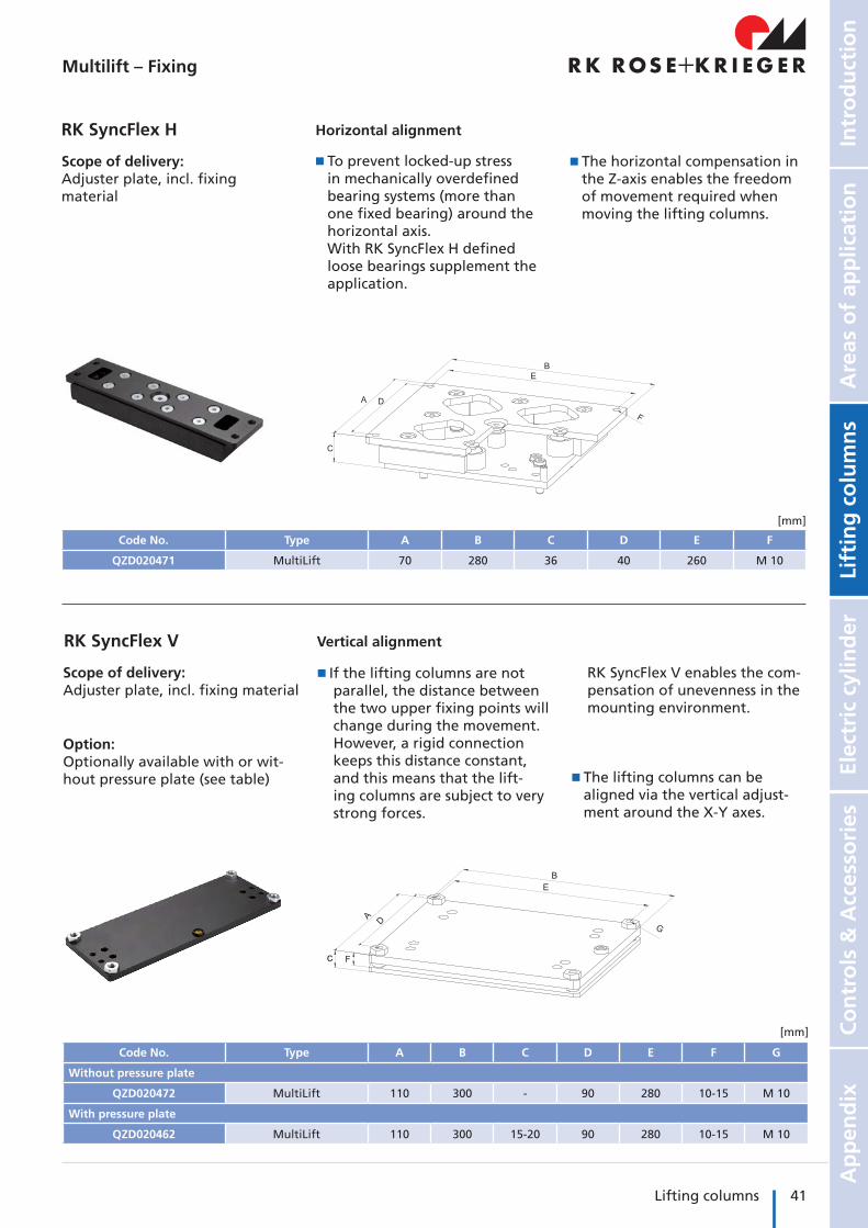
Code No. Type A B C D E F
QZD020471 MultiLift 70 280 36 40 260 M 10
RK SyncFlex H
Scope of delivery: Adjuster plate, incl. fixing material
� The horizontal compensation in the Z-axis enables the freedom of movement required when moving the lifting columns.
� To prevent locked-up stress in mechanically overdefined bearing systems (more than one fixed bearing) around the horizontal axis. With RK SyncFlex H defined loose bearings supplement the application.
Horizontal alignment
[mm]
Code No. Type A B C D E F G
Without pressure plate
QZD020472 MultiLift 110 300 - 90 280 10-15 M 10
With pressure plate
QZD020462 MultiLift 110 300 15-20 90 280 10-15 M 10
Scope of delivery:Adjuster plate, incl. fixing material
Option: Optionally available with or wit-hout pressure plate (see table)
RK SyncFlex V
� The lifting columns can be aligned via the vertical adjust-ment around the X-Y axes.
� I f the lifting columns are not parallel, the distance between the two upper fixing points will change during the movement. However, a rigid connection keeps this distance constant, and this means that the lift-ing columns are subject to very strong forces.
Vertical alignment
RK SyncFlex V enables the com-pensation of unevenness in the mounting environment.
Multilift – Fixing
42 Lifting columns
Multilift – Fixing
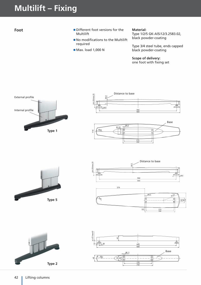
Foot � Different foot versions for the Multilift
� No modifications to the Multilift required
�Max. load 1,000 N
Material:Type 1/2/5 GK-AlSi12/3.2583.02, black powder-coating Type 3/4 steel tube, ends cappedblack powder-coating
Scope of delivery:one foot with fixing set
External profile
Internal profile
Type 1
Type 5
Type 2
Distance to base
Distance to base
Base
Base

43Lifting columns
Intr
od
uct
ion
Lift
ing
co
lum
ns
Elec
tric
cyl
ind
erC
on
tro
ls &
Acc
esso
ries
Ap
pen
dix
Are
as o
f ap
plic
atio
n
Type 3
Type 4
Code No. Type
QZD020252 1
QZD020253 2
QZD020254 3
QZD020255 4
QZD020343 5
Multilift - Fixing
Multilift centrally mounted (choice of internal or external profile)
Multilift mounted off-centre (choice of internal or external profile)

44 Lifting columns
Multilift – Drive / Accessories
Code No. Version
Controls for Multilift mono
QZA07C13AX021 Transformer control 120 VA connection A, up to max. 3 A current output, 24 V DC Controls up to 2 drives
QSTAACA1AA000 MultiControl mono connection A, up to max. I= 10 A current output, 24 V DC Controls up to 2 drives
Controls for Multilift synchro
QST10C02AA000 MultiControl duo connection C, up to max. 12 A current output, 36 V DCControls up to 2 drives synchronous
QST10C04AA000 MultiControl quadro connection C, up to max. 12 A current output, 36 V DCControls up to 4 drives synchronous
Accessories
QZD020083 Fixing plate 120 VA, control is pushed onto the plate
QZD100093 6 m bus cable for the networking of up to 8 synchronous controls
QZD0702844000* Straight connecting cable (4 m) with 5-pin connector and open cable end
QZD070525 Extension cable 2,5 m drive for connector A / 2-pin DIN socket
QZD070526 Extension cable 2,5 m drive for connector C / 8-pin DIN socket
� Input voltage 230 V AC
�Output voltage 24/36 V DC
� For battery operated controls
For dimensions and other technical data, please refer to the chapter „Motors and controls“
Controls
Transformer control 120 VA
approx. 24 V DC approx. 36 V DC
MultiControl
*for the connection of a parallel hand switch or an external potentiometer (in the case of the MultiControl mono)
Order information: Observe the current output of the drives when selecting the control.

45Lifting columns
Intr
od
uct
ion
Lift
ing
co
lum
ns
Elec
tric
cyl
ind
erC
on
tro
ls &
Acc
esso
ries
Ap
pen
dix
Are
as o
f ap
plic
atio
n
7 8
9
1 2
3
13down
up
14
� This interface enables actua-tion of the synchronous control system via different input devices (PLC, PC and hand switch)
� You will find further product information on page 182
Note:For further hand switch versions, please refer to the chapter “Controls” on page 146
Hand switches/accessories
Multilift - Drive / Accessories
Code No. Type
QZD100108 PLC/PC data interface
QZD100110 Fixing plate for mounting in a control cabinet
PLC/PCdata interface Multilift
Input Output
Hand switch
PC
PLC
Processing
Synchronous control
PLC/PCdata interface
Code No. Version Fig.
Hand switch for transformer control
QZB02C03AD031 Hand switch with 1 m spiral cable – 6 function keys 2
Hand switches for transformer or synchronous control
QZB02C03AB031 Hand switch with 1 m spiral cable – 2 function keys 1
QZB00D04AB041 Hand switch with 1 m spiral cable – 2 function keys 7
QZB02C01AE114 Foot switch – 2 function keys 13
QZB00D07BK141 Wireless hand switch – 2 function keys 14
Hand switch for synchronous control
QZB00D04AD041 Hand switch with 1 m spiral cable – 6 function keys 8
Accessories for hand switches
QZD000072 Bracket for hand switch: Fig. 1 + 2 3
QZD000074 Hand switch drawer: Fig. 7 + 8 9

We say what we do - and do what we say!We also say what we can‘t do - and don‘t do it!
Connecting and positioning systems
RK Rose+Krieger GmbHPostfach 15 64D-32375 MindenTelephone: +49 (5) 71/9335-0Fax: +49 (5) 71/9335-119E-Mail: [email protected]: www.rk-rose-krieger.com