multiple access protocal
TRANSCRIPT

MULTIPLE ACCESS
PROTOCOL

RANDOM ACCESS
• A station that has data to send uses a procedure defined by a protocol
to make a decision on whether or not to send.
• This decision depends on the state of the medium(idle or busy).
• There is no scheduled time for a station to transmit. Transmission
is random among the stations. That is why these methods are
called random access.
• No rules specify which station should send next . Stations compete
with one another to access the medium. That is why these
methods are also called contention methods.
• If more than one station tries to send at a time , there is an access
conflict - collision

RANDOM ACCESS PROTOCOL
• ALOHA
(Pure ALOHA and Slotted ALOHA)
• CSMA
• CSMA/CD
• CSMA/CA

ALOHA PROTOCOL
• ALOHA is developed in the 1970s at the University of Hawaii.
• The basic idea is simple:• Let users transmit whenever they have data to be sent.
• If two or more users send their packets at the same time, a collision occurs and the packets are destroyed.

ALOHA Protocol
• The original ALOHA protocol is called pure ALOHA.
• Each station sends a frame whenever it has a frame to
send.
• However , there is only one channel for them to share.

• If two or more stations transmit at same time, there is a
collision
• the sender waits a random amount of time and sends it
again.
• The waiting time must be random. Otherwise, the same
packets will collide again.

12.8
Figure 12.3 Frames in a pure ALOHA network

A Sketch of Frame Generation

Efficiency in ALOHA Channel
S = GP0
S: Throughput
G: Mean of Regenerated and New frames
P0: Probability that a frame does not suffer a collision

11
ALOHA’s Performance (Cont’d)
• S = G e-2G, where S is the throughput (rate of successful
transmissions) and G is the offered load.
• S = Smax = 1/2e = 0.184 for G=0.5.

SLOTTED ALOHA
• In slotted aloha we divide the time into slots.
• Frames can only be transmitted at beginning of slot: “discrete”
ALOHA.

SLOTTED ALOHA

SLOTTED ALOHA
Efficiency
• S = G e-G.
• S = Smax = 1/e = 0.368 for G = 1.

•CSMA protocol was developed to overcome the problem found in
ALOHA i.e. to minimize the chances of collision, so as to
improve the performance.
•CSMA protocol is based on the principle of ‘carrier sense’.
•The chances of collision can be reduce to great extent if a station
senses the channel before trying to use it.
• Although CSMA can reduce the possibility of collision, but it
cannot eliminate it completely.
CARRIER SENSE MULTIPLE ACCESS


1-persistent CSMA
While there is a new frame A to send do
1. Check the medium
2. If the medium is busy, go to 1.
3. (medium idle) Send frame A and wait for ACK
4. If after some time ACK is not received (timer times out), wait a random amount of time and go to 1.
End.

Non-persistent CSMA
While there is a new frame A to send DO
1. Check the medium
2. If the medium is busy, wait some time, and go to 1.
3. (medium idle) Send frame A and wait for ACK
4. If after some time ACK is not received (timer times out), wait a random amount of time and go to 1.
End

p-persistent CSMA
While there is a new frame A to send do
1. Check the medium
2. If the medium is busy, go to 1.
3. (medium idle) With probability p send frame A and the go to 4, and probability (1- p) delay one time slot and go to 1.
4. If after some time ACK is not received (timer times out), wait a random amount of time and go to 1.
End.

20
CSMA/CD
• CSMA with collision detection.
• Problem: when frames collide, medium is unusable for duration of both (damaged) frames.
• For long frames (when compared to propagation time), considerable waste.
• What if station listens while transmitting?

21
CSMA/CD Protocol
1. If medium idle, transmit; otherwise 2.
2. If medium busy, wait until idle, then transmit with p=1.
3. If collision detected, transmit brief jamming signal and
abort transmission.
4. After aborting, wait random time, try again.

WIRED LANS

ETHERNET
Ethernet is a family of computer networking technologies for local area
(LAN) and larger networks.
A LAN market has seen several technologies such as Ethernet , Token
Ring , Token Bus , FDDI , and ATM LAN. Some of these technologies
survived for a while, but Ethernet is by far the most dominant
technology

IEEE STANDARDS
In 1985 , the Computer Society of the IEEE started a project , called Project
802, to set standards to enable intercommunication among equipment from a
variety of manufactures
It is a way of specifying functions of the physical layer and the data link layer
of major LAN protocols
The IEEE subdivided the data link layer into 2 sublayers
1) Logical link control (LLC)
2) Media Access Control (MAC)
The IEEE also created several physical layer standards for different LAN
protocols

LOGICAL LINK CONTROL
• In the seven-layer OSI model of computer networking, the logical link
control (LLC) data communication protocol layer is the upper sublayer
of the data link layer. It provides flow control, error control and a part
of the framing duties
• The LLC provides one single data link control protocol for all IEEE
LAN’s
• It provides interconnectivity between different LAN’s
• The LLC sublayer acts as an interface between the media access
control (MAC) sublayer and the network layer.
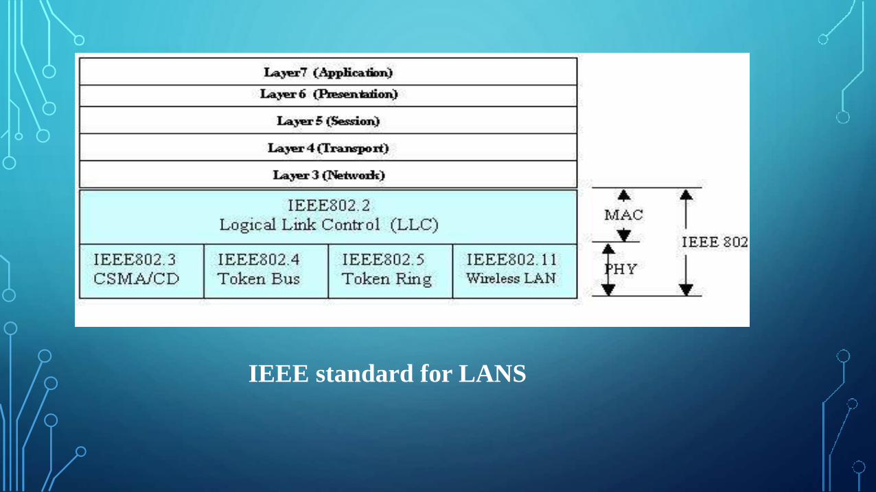
IEEE standard for LANS

FRAMING
• LLC defines a protocol data unit (PDU)
• PDU : Information that is delivered as a unit among peer entities of a
network and that may contain control information, such as address
information, or user data.
• One header contains a control field which is used for flow and error control.
• 2 other header fields define upper layer protocol at the source and
destination that use LLC. These fields are called destination service access
point (DSAP) and the source service access point (SSAP)
• Other fields are moved to the MAC sublayer.

NEED FOR LLC
The purpose of LLC is to provide flow and error
control for the upper-layer protocols that actually
demand these services.

MEDIA ACCESS CONTROL
• The MAC sublayer provides addressing and channel access control
mechanisms that make it possible for several terminals or network nodes to
communicate within a multiple access network that incorporates a shared
medium (defines access method for each LAN)
• A part of framing is also handled by the MAC layer
• In contrast to the LLC sublayer, the MAC sublayer contains a number of
distinct modules , each define the access method and the framing format
specific to the corresponding LAN protocol

LLC PDU
MAC frame
PHYSICAL LAYER
• The physical layer is dependant on the implementation and the type of
physical media used
• IEEE defines detailed specification for each LAN implementation
• There is a different physical layer specification for each Ethernet
implementations

DIFFERENT GENERATIONS OF ETHERNET
Ethernet has gone through 4 generations
• Standard Ethernet(10 Mbps)
• Fast Ethernet(100 Mbps)
• Gigabit Ethernet(1 Gbps)
• Ten-Gigabit Ethernet(10 Gbps)

STANDARD ETHERNET
In Standard Ethernet , the MAC sublayer governs the operation of the
access method. It also frames data received from the upper layer and
passes them to the physical layer

FRAME FORMAT
Ethernet frame contains 7 fields
• Preamble
• SFD
• DA
• SA
• Length or type of protocol data unit (PDU)
• Upper-layer data
• CRC


PREAMBLE
• It contains 7 bytes of alternating 0’s and 1’s that alerts the receiving
system to the coming frame and enables it to synchronize its input
timing
• It provides only an alert and the pattern allows the stations to miss
some bytes at the beginning of the frame
• It is actually added at the physical layer

START FRAME DELIMITER (SFD)
• Signals the beginning of the frame
• Warns the stations that this is the last chance for synchronization
• The last 2 bits are 11 and alerts the receiver that the next field is the
destination address

DESTINATION ADDRESS (DA)
• 6 bytes
• Contains the physical address of the destination station to receive the
packet

SOURCE ADDRESS (SA)
• 6 bytes
• Contains physical address of the sender of the packet.

LENGTH
Used as a length field to define the number of bytes in the data field

DATA
• Carries the data encapsulated from the upper layer protocols
• Minimum 46 bytes
• Maximum 1500 bytes

CRC
This field contains error detection information

FRAME LENGTH
• Minimum length of data from upper layer is 46 bytes
• If the data is less than 46 bytes , padding is added to make up the
difference
• Maximum length of data from upper layer is 1500 bytes
• Memory was very expensive when Ethernet was designed, maximum
length restriction helped to reduce the size of the buffer
• Maximum length restriction prevents one station from monopolizing
the shared medium , blocking other stations that have data to send

ADDRESSING
Each station on an Ethernet network has its own network interface card
(NIC)
It provides the station with a 6-byte physical address , normally written
in a hexadecimal notation , with a colon between the bytes ,for eg.
06 : 01 : 02 : 2C : 4B

DIFFERENT TYPES
• Unicast : one–to-one
• Multicast : one-to –many
• Broadcast : recipients are all the stations on the LAN
If the least significant bit of the 1st byte in a destination address is 0 ,
the address is unicast; otherwise it is a multicast

ACCESS METHOD : CSMA/CD
It uses a carrier sensing scheme in which a transmitting data station
detects other signals while transmitting a frame, and stops transmitting
that frame, transmits a jam signal, and then waits for a random time
interval before trying to resend the frame.

SLOT TIME
The round trip time required for a frame to travel form one end of a
maximum-length network to the other plus the time needed to send the
jam sequence is called the slot time

MAXIMUM NETWORK LENGTH
There is a relationship between slot time and the maximum length of
the network . It’s dependant on the propagation speed which is 2 * 10 8
MaxLength = PropagationSpeed X SlotTime/2

ENCODING AND DECODING
• At the sender, data is converted to a digital signal using the
Manchester scheme
• At the receiver , the received signal is interpreted as Manchester and
decoded into data
• Manchester coding is self-synchronous, providing a transition at each
bit interval

MANCHESTER ENCODING

10BASE5 : THICK ETHERNET
• Uses a bus topology with an external transceiver connected to a thick
coaxial cable
• Transceiver is responsible for transmitting , receiving and detecting
collisions . It is connected to the station via a transceiver cable that
provides separate paths for sending and receiving
• Maximum length of the coaxial cable must not exceed 500m ,
otherwise, there is excessive degradation of signal (Repeaters can be
connected) .

10Base5 implementation

10BASE2 : THIN ETHERNET
• Uses a bus topology , but the cable is much thinner and flexible
• Transceiver is normally part of the network interface card (NIC) ,
which is installed inside the station.
• This implementation is more cost effective , installation is simpler
• Length of each segment cant exceed 185m

10Base2 implementation

10BASE-T : TWISTED – PAIR ETHERNET
• Uses a physical star topology , stations are connected to a hub via
two pairs of twisted cable
• Two pairs of twisted pair create two paths ( one for sending and one
for receiving ) between the station and hub .
• Collisions here happen in the hub
• Maximum length of the twisted cable here is 100m

10Base-T implementation

10BASE-F : FIBER ETHERNET
• Uses a star topology to connect stations to a hub
• Stations are connected to a hub via fiber-optic cables

13.5
8
13-3 CHANGES IN THE STANDARD
The 10-Mbps Standard Ethernet has gone through several changes before moving to the higher data rates. These
changes actually opened the road to the evolution of the Ethernet to become compatible with other high-data-rate
LANs. Topics discussed in this section: Bridged Ethernet;Switched Ethernet; Full-Duplex Ethernet.
Bridged Ethernet
The first step in the Ethernet evolution was the division of a LAN by bridges. Bridges
have two effects on an Ethernet LAN: They raise the bandwidth and they separate collision domains.
In an unbridged Ethernet network, the total capacity (10 Mbps) is shared among all stations with a frame to send; the
stations share the bandwidth of the network. If only one station has frames to send, it benefits from the total capacity
(10 Mbps). But if more
than one station needs to use the network, the capacity is shared. For example, if two
stations have a lot of frames to send, they probably alternate in usage. When one station
is sending, the other one refrains from sending. We can say that, in this case, each station on average, sends at a rate
of 5 Mbps.

13.5
9
A bridge divides the network into two or more networks. Bandwidth-wise, each network is independent. For example,
a network with 12 stations is divided into two networks, each with 6 stations. Now each network has a capacity of 10
Mbps. The 10-Mbps capacity in each segment is now shared between 6 stations (actually 7 because the bridge acts as
a station in each segment), not 12 stations. In a network with a heavy load, each station theoretically is offered 10/6
Mbps instead of 10/12 Mbps, assuming that the traffic is not going through the bridge. You can see that the collision
domain becomes much smaller and the probability of collision is reduced tremendously.
Collision domains in an unbridged network and a bridged network

13.6
0
Switched Ethernet: The idea of a bridged LAN can be extended to a switched LAN. Instead of having two to four
networks, why not have N networks, where N is the number of stations on the LAN? In other words, if we can have a
multiple-port bridge, why not have an N-port switch? In this way, the bandwidth is shared only between the station
and the switch (5 Mbps each). In addition, the collision domain is divided into N domains. A layer 2 switch is an N-
port bridge with additional sophistication that allows faster handling of the packets. Evolution from a bridged
Ethernet to a switched Ethernet was a big step that opened the way to an even faster Ethernet.
Full-Duplex Ethernet: One of the limitations of 10Base5 and 10Base2 is that communication is half-duplex (10Base-T is
always full-duplex); a station can either send or receive, but may not do both at the same time. The next step in the
evolution was to move from switched Ethernet to full-duplex switched Ethernet. The full-duplex mode increases the
capacity of each domain from 10 to 20 Mbps.Figure13.18 shows a switched Ethernet in full-duplex mode. Note that
instead of using one link between the station and the switch, the configuration uses two links: one to transmit and one
to receive.

13.6
1
No Need for CSMA/CD
In full-duplex switched Ethernet, there is no need for the CSMA/CD method. In a full-
duplex switched Ethernet, each station is connected to the switch via two separate links.
Each station or switch can send and receive independently without worrying about collision. Each link is a point-to-
point dedicated path between the station and the switch. There is no longer a need for carrier sensing; there is no
longer a need for collision detection. The job of the MAC layer becomes much easier. The carrier sensing and
collision detection functionalities of the MAC sublayer can be turned off.
MAC Control Layer
Standard Ethernet was designed as a connectionless protocol at the MAC sublayer.
There is no explicit flow control or error control to inform the sender that the frame has
arrived at the destination without error. When the receiver receives the frame, it does
not send any positive or negative acknowledgment. To provide for flow and error control in full-duplex switched
Ethernet, a new sublayer, called the MAC control, is added between the LLC sublayer and the MAC sublayer.

13.6
2
13-4 FAST ETHERNET
Fast Ethernet was designed to compete with LAN protocols such as FDDI or Fiber Channel. IEEE created Fast
Ethernet under the name 802.3u. Fast Ethernet is backward-compatible with Standard Ethernet, but it can transmit
data 10 times faster at a rate of 100 Mbps. The goals of Fast Ethernet can be summarized as follows:
1. Upgrade the data rate to 100 Mbps. 2. Make it compatible with Standard Ethernet.
3. Keep the same 48-bit address. 4. Keep the same frame format.
5. Keep the same minimum and maximum frame lengths.
MAC Sublayer: A main consideration in the evolution of Ethernet from 10 to 100 Mbps was to keep the MAC
sublayer untouched. However, a decision was made to drop the bus topologies and keep only the star topology. For
the star topology, there are two choices, as we saw before: half duplex and full duplex. In the half-duplex approach,
the stations are connected via a hub; in the full-duplex approach, the connection is made via a switch with buffers at
each port.
Autonegotiation: A new feature added to Fast Ethernet is called autonegotiation. It allows a station or a hub a range
of capabilities. Autonegotiation allows two devices to negotiate the mode or data rate of operation. It was designed
particularly for the following purposes:•1. To allow incompatible devices to connect to one another. For example, a
device with a maximum capacity of 10 Mbps can communicate with a device with a 100 Mbps capacity (but can work
at a lower rate). 2. To allow one device to have multiple capabilities. 3. To allow a station to check a hub's
capabilities.

13.6
3
Physical Layer: The physical layer in Fast Ethernet is more complicated than the one in Standard Ethernet. We
briefly discuss some features of this layer.
Topology
Fast Ethernet is designed to connect two or more stations together. If there are only two
stations, they can be connected point-to-point. Three or more stations need to be con-
nected in a star topology with a hub or a switch at the center.
Fast Ethernet implementations

13.6
4
13-5 GIGABIT ETHERNETThe need for an even higher data rate resulted in the design of the Gigabit Ethernet protocol (1000 Mbps). The
IEEE committee calls the standard 802.3z.
In the full-duplex mode of Gigabit Ethernet, there is no collision; the maximum length of the cable is
determined by the signal attenuation in the cable.
Topology
Gigabit Ethernet is designed to connect two or more
stations. If there are only two stations, they can be
connected point-to-point. Three or more stations need
to be connected in a star topology with a hub or a
switch at the center. Another possible configuration is
to connect several star topologies or let a star topology
be part of another.

13.6
5
Gigabit Ethernet implementations

13.6
6
MAC Sublayer
Ten-Gigabit Ethernet operates only in full duplex mode which means there is no
need for contention; CSMA/CD is not used in Ten-Gigabit Ethernet.
Physical Layer : The physical layer in Ten-Gigabit Ethernet is designed for using
fiber-optic cable over long distances.

THANK YOU