multiple-input-multiple-output (mimo) systems · multiple-input-multiple-output (mimo) systems deke...
TRANSCRIPT

Multiple-Input-Multiple-Output (MIMO) Systems
Deke GuoNational University of Defense Technology
2012.03
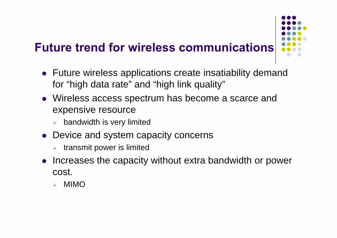
Future trend for wireless communications
Future wireless applications create insatiability demand for “high data rate” and “high link quality”
Wireless access spectrum has become a scarce and expensive resource bandwidth is very limited
Device and system capacity concerns transmit power is limited
Increases the capacity without extra bandwidth or power cost. MIMO

Multi-input multi-output (MIMO) concept
Basic idea of MIMO: Improve quality (BER) and/or data rate (bits/sec) by using multiple TX/RX antennas
Core scheme of MIMO: space-time coding (STC) Two main functions of STC: diversity & multiplexing Maximum performance needs tradeoffs between diversity and
multiplexing
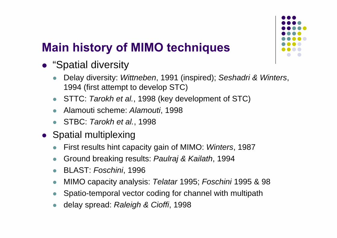
Main history of MIMO techniques “Spatial diversity
Delay diversity: Wittneben, 1991 (inspired); Seshadri & Winters, 1994 (first attempt to develop STC)
STTC: Tarokh et al., 1998 (key development of STC) Alamouti scheme: Alamouti, 1998 STBC: Tarokh et al., 1998
Spatial multiplexing First results hint capacity gain of MIMO: Winters, 1987 Ground breaking results: Paulraj & Kailath, 1994 BLAST: Foschini, 1996 MIMO capacity analysis: Telatar 1995; Foschini 1995 & 98 Spatio-temporal vector coding for channel with multipath delay spread: Raleigh & Cioffi, 1998

Four basic models
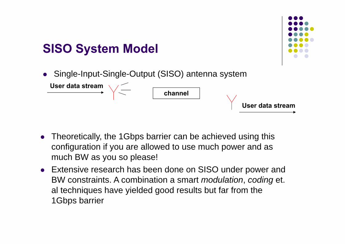
SISO System Model
Single-Input-Single-Output (SISO) antenna system
Theoretically, the 1Gbps barrier can be achieved using this configuration if you are allowed to use much power and as much BW as you so please!
Extensive research has been done on SISO under power and BW constraints. A combination a smart modulation, coding et. al techniques have yielded good results but far from the 1Gbps barrier
channelUser data stream
User data stream
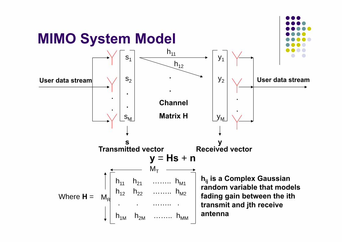
MIMO System Model
y = Hs + n
User data stream
.
.
User data stream
.
..
.Channel
Matrix H
s1
s2
sM
s
y1
y2
yM
yTransmitted vector Received vector
.
.
h11
h12
Where H =
h11 h21 …….. hM1
h12 h22 …….. hM2
h1M h2M …….. hMM
. . …….. .
MT
MR
hij is a Complex Gaussian random variable that models fading gain between the ith transmit and jth receive antenna

MIMO Channel Capacity
Multipath v.s. capacity Multipath propagation has long been regarded as an “impairment”
because it causes signal fading To mitigate this problem, diversity techniques were developed
Antenna diversity is a widespread form of diversity Recent research has shown that multipath propagation can in
fact “contribute” to capacity
Information theory has shown that with multipath propagation, multiple antennas at both transmitter and receiver can establish essentially multiple parallel channels that operate simultaneously, on the same frequency band at the same total radiated power
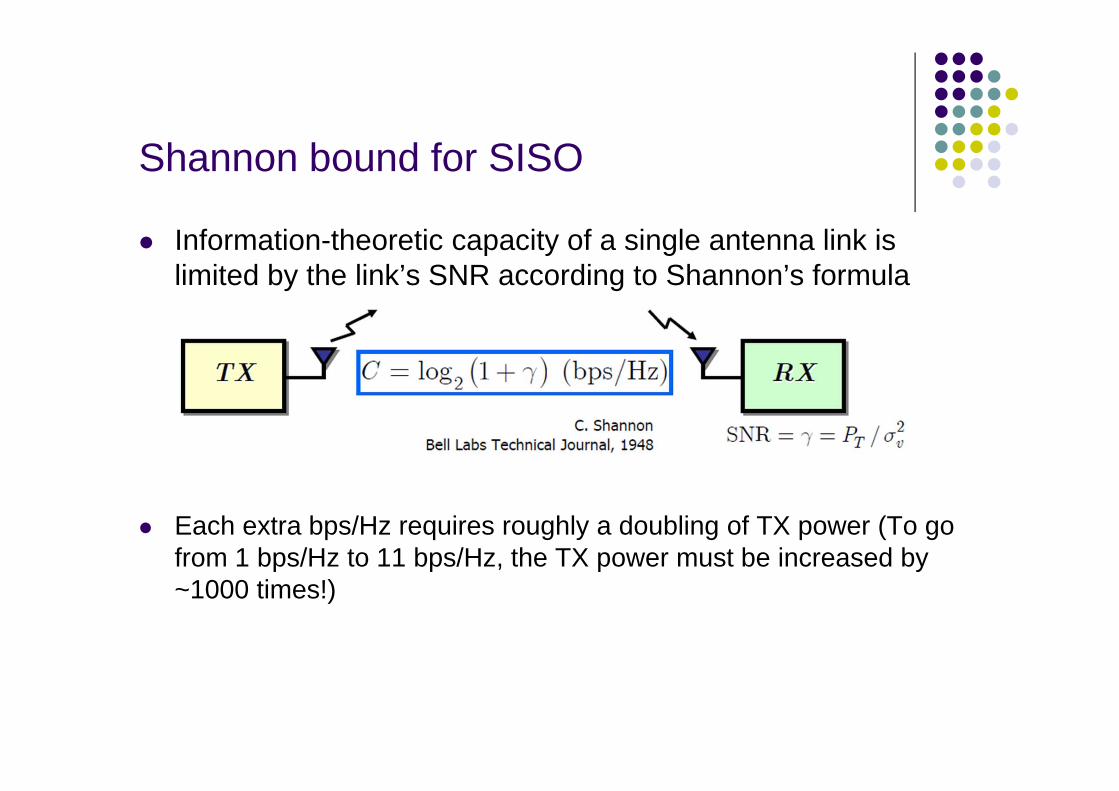
Shannon bound for SISO
Information-theoretic capacity of a single antenna link is limited by the link’s SNR according to Shannon’s formula
Each extra bps/Hz requires roughly a doubling of TX power (To go from 1 bps/Hz to 11 bps/Hz, the TX power must be increased by ~1000 times!)
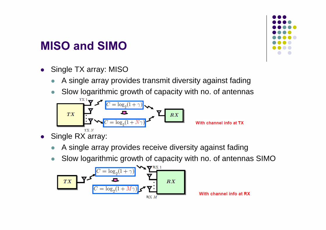
MISO and SIMO
Single TX array: MISO A single array provides transmit diversity against fading Slow logarithmic growth of capacity with no. of antennas
Single RX array: A single array provides receive diversity against fading Slow logarithmic growth of capacity with no. of antennas SIMO

MIMO
Diversity: Dual array provides diversity at both TX and RX ends Slow logarithmic growth of capacity with no. of antennas
Multiplexing Dual array provides parallel spatial channels Linear growth of capacity with no. of antennas
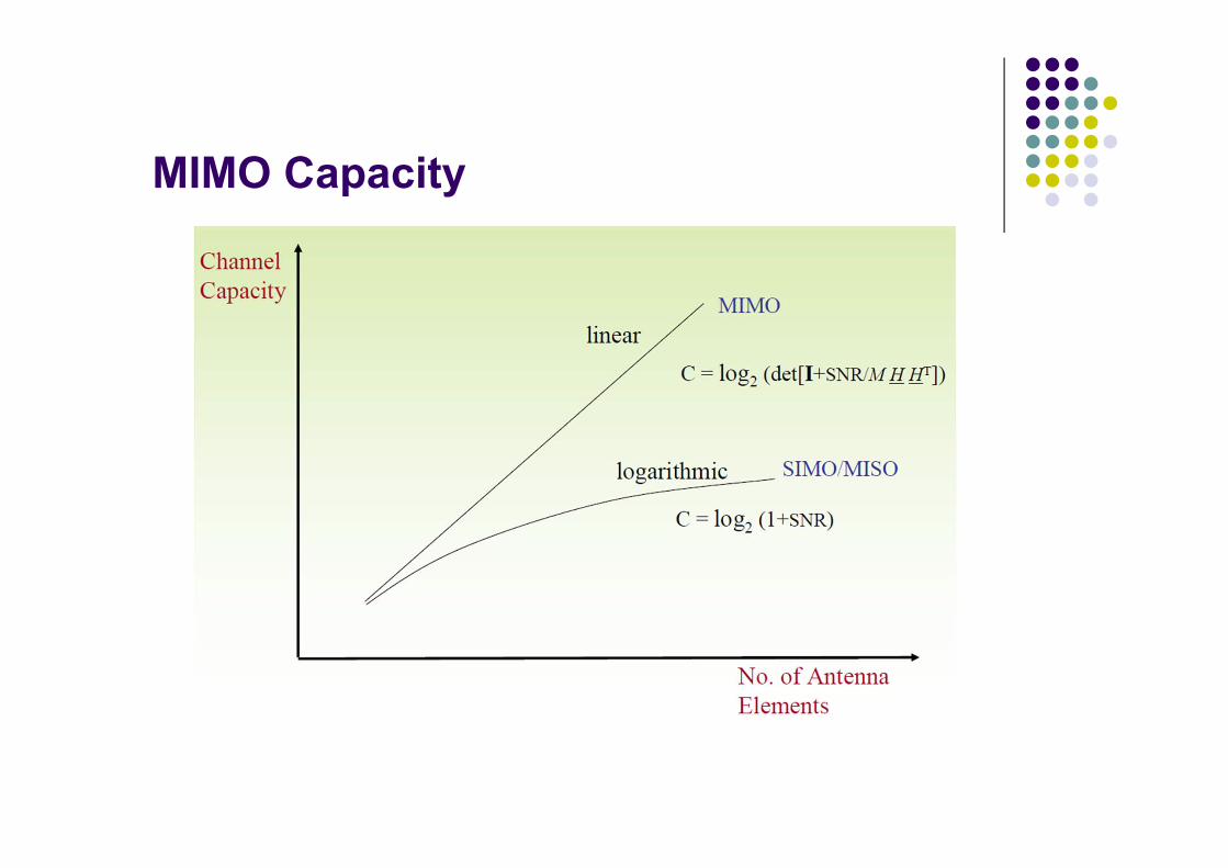
MIMO Capacity
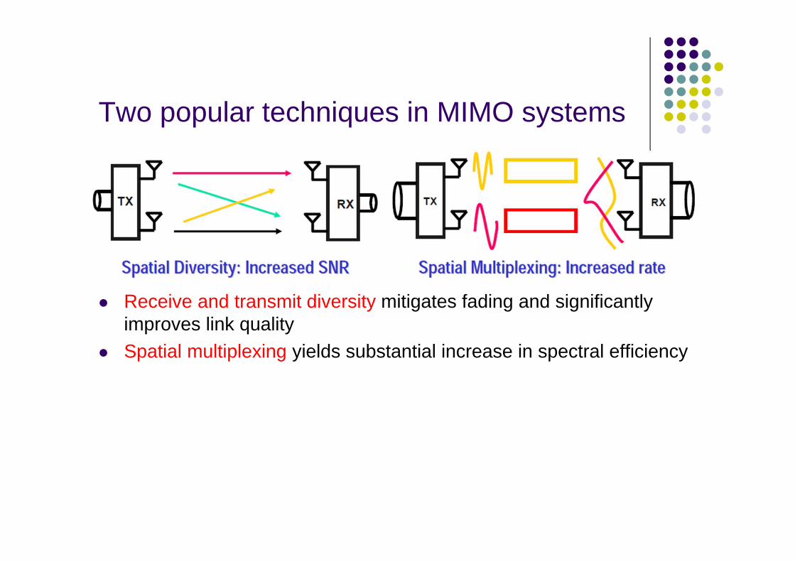
Two popular techniques in MIMO systems
Receive and transmit diversity mitigates fading and significantly improves link quality
Spatial multiplexing yields substantial increase in spectral efficiency

Spatial Diversity
Sending the dependent information through different paths, multiple independently-faded replicas of the data symbol can be obtained at the receiver end. Hence, more reliable reception is achieved
The maximal diversity gain dmax is the total number of independent signal paths between the transmitter and receiver
For an (MR,MT) system, the total number of signal paths is MRMT
The higher the diversity gain, the lower my Pe
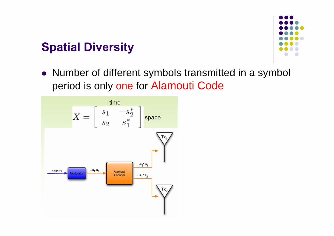
Spatial Diversity
Number of different symbols transmitted in a symbol period is only one for Alamouti Code
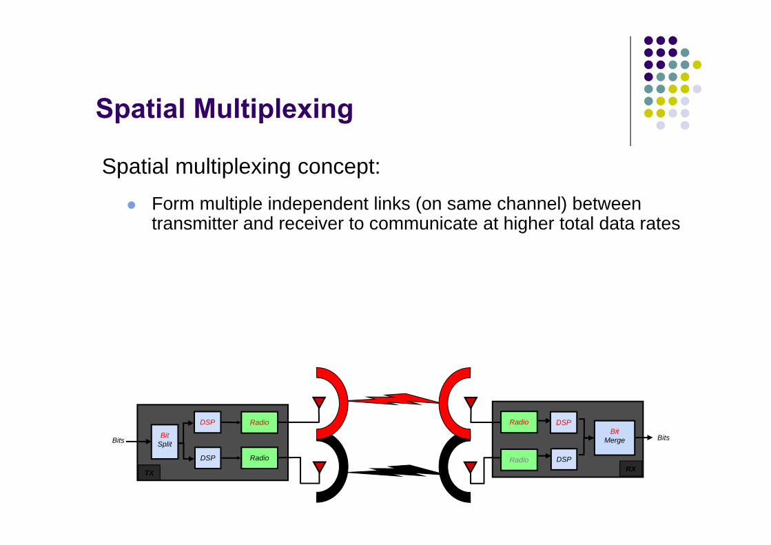
Spatial Multiplexing
Spatial multiplexing concept: Form multiple independent links (on same channel) between
transmitter and receiver to communicate at higher total data rates
Radio
Radio
DSP
DSP
BitSplitBits
BitMerge
TX
Radio
RadioRX
Bits
DSP
DSP

Spatial Multiplexing
Spatial multiplexing concept:
Form multiple independent links (on same channel) between transmitter and receiver to communicate at higher total data rates
However, there are cross-paths between antennas
Radio
Radio
DSP
DSP
BitSplitBits
BitMerge
TX
Radio
RadioRX
Garbage
DSP
DSP

Spatial Multiplexing
Radio
Radio
DSP
DSP
DSP
BitSplitBits
BitMerge
TX
Radio
Radio
Bits
RX
Spatial multiplexing concept:
Form multiple independent links (on same channel) between transmitter and receiver to communicate at higher total data rates
However, there are cross-paths between antennas
The correlation must be decoupled by digital signal processing algorithms

Spatial Multiplexing

Spatial Multiplexing
Requires multiple antennas at both ends of radio link. Increase in data rate by transmitting independent information streams on different antennas. If scattering is rich enough (i.e. high rank channel H) several
spatial data pipes are created within the same bandwidth. Multiplexing gain comes at no extra bandwidth or power.

Practical System
Redundancy in time
Coding rate = rc Space- time redundancy over T symbol periods
Spatial multiplexing gain = rs
1
2
MT
Channel coding
Symbol mapping
Space-Time
Coding
.
.
R bits/symbol
rs : number of different symbols N transmitted in T symbol periods
rs = N/T
** If rs = MT, we are in spatial multiplexing
**If rs ≤ 1, we are in diversity mode

V-BLAST – Spatial Multiplexing (Vertical Bell Labs Layered Space-Time Architecture)
This is the only architecture that goes all out for maximum rate.
.
.
s1
s2
sM
s
User data stream .
.
User data stream.
.
y1
y2
yM
y
.
.
H V-BLAST Processing
Split data into MT streams maps to symbols send Assume receiver knows H Uses old technique of ordered successive cancellation to
recover signals In one symbol period, sending MT different symbols

Linear precoding Precoding is a processing technique that exploits CSIT by operating
on the signal before transmission. A linear precoder is optimal from an information theoretic view point.
It splits the transmit signal into orthogonal spatial eigenbeams and assigns higher power along the beams where the channel is strong but lower or no power along the weak.
Equal beam power Unequal beam power

Precoding System Structure

Linear precoding
Let the singular value decomposition (SVD) of the channel beLet M be VH and W be U∗
H
Multiplying the signal at the transmitter with M, in which each column is referred to as a transmitting weight vector for a symbol of x.
Multiplying the signal at the receiver with W, in which each row is referred as a receiving weight vector.

Multi-user MIMO systems
Broadcast channel (BC): down link Multiple-access channel (MAC): up link

TDMA-based multiplexing
TDMA-based multiplexing : scheduling In this setting, MIMO enhances the potential network throughput via
spatial multiplexing by achieving high data rates.
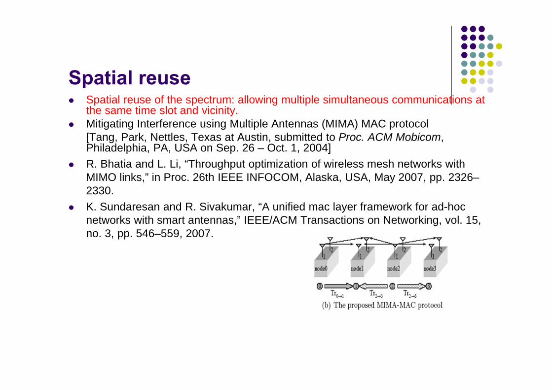
Spatial reuse Spatial reuse of the spectrum: allowing multiple simultaneous communications at
the same time slot and vicinity. Mitigating Interference using Multiple Antennas (MIMA) MAC protocol
[Tang, Park, Nettles, Texas at Austin, submitted to Proc. ACM Mobicom, Philadelphia, PA, USA on Sep. 26 – Oct. 1, 2004]
R. Bhatia and L. Li, “Throughput optimization of wireless mesh networks with MIMO links,” in Proc. 26th IEEE INFOCOM, Alaska, USA, May 2007, pp. 2326–2330.
K. Sundaresan and R. Sivakumar, “A unified mac layer framework for ad-hoc networks with smart antennas,” IEEE/ACM Transactions on Networking, vol. 15, no. 3, pp. 546–559, 2007.

Spatial reuse Each MIMO link only employs partial degree-of-freedoms to transmit
and receive data streams. stream control: best degree-of-freedoms are selected for data
transmissions, while others at the receiver are used to suppress interfering data streams
interference avoidance: the transmitter selects appropriatedegree-of-freedoms to transmit data streams such that the remaining degree-of-freedoms can null its data streams at undesired active receivers.

Stream Control
If stream control and spatial multiplexing transmit the same number of data streams, stream control outperforms spatial multiplexing in terms of the network throughput.
Although a MIMO channel can be decomposed into multiple parallel sub-channels, their capacities have quite large disparities for moderate or low SNR
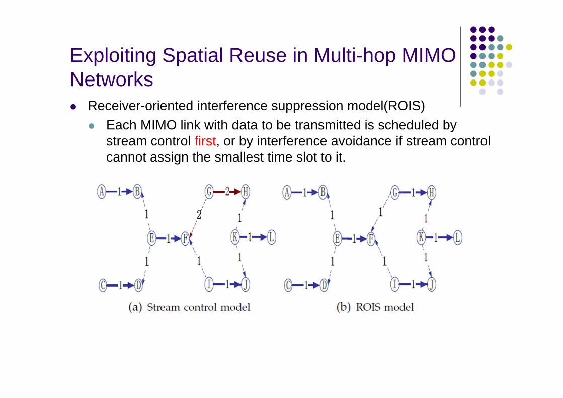
Exploiting Spatial Reuse in Multi-hop MIMO Networks Receiver-oriented interference suppression model(ROIS)
Each MIMO link with data to be transmitted is scheduled by stream control first, or by interference avoidance if stream control cannot assign the smallest time slot to it.
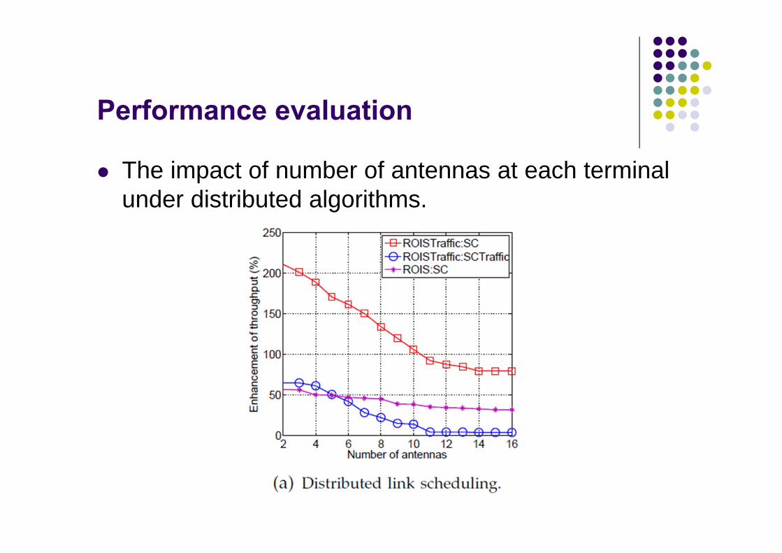
Performance evaluation
The impact of number of antennas at each terminal under distributed algorithms.
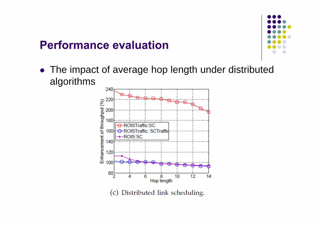
Performance evaluation
The impact of average hop length under distributed algorithms
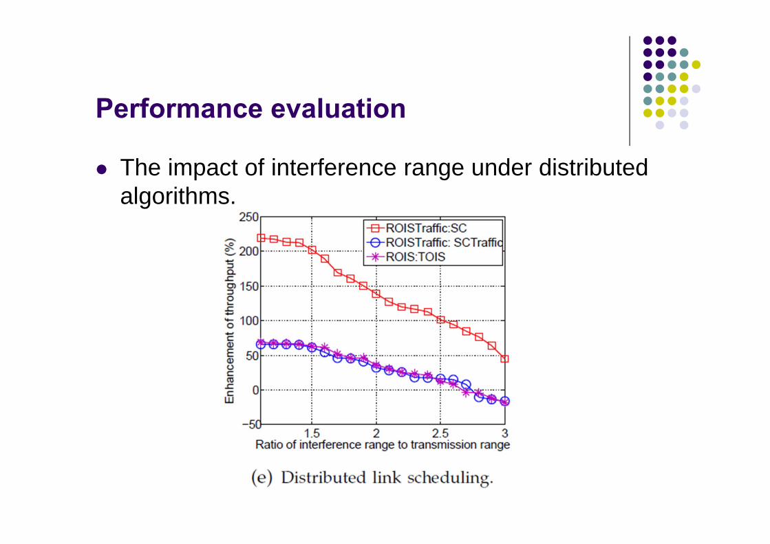
Performance evaluation
The impact of interference range under distributed algorithms.
Summary/Conclusions
Point-to-Point MIMO Systems Multi-user MIMO systems Multi-hop MIMO networks