multiplexing and switching(tdm ,fdm, data gram, circuit switching)
TRANSCRIPT

Multiplexing and Switching

Multiplexing
Sharing the link among multiple users

Multiplexing
Time Division Multiplexing (TDM) Synchronous TDM Statistical TDM
Frequency Division Multiplexing (FDM)

Time Division Multiplexing
The Basic Idea:
As the name suggest, Divide time amongst the users
Give each user some time to transmit his data This process is periodic in a round robin fashion The time given to a each user is referred to as
Time Slot or Time Quantum

Time Division Multiplexing

MUX
12
1
3
23
123
THE TRANSMITTER
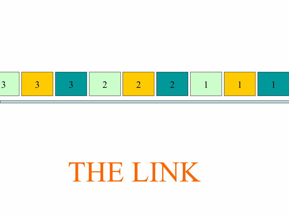
12 13 23 123
THE LINK

DEMUX
THE RECEIVER

There should be no Timing difference between the
MUX and DEMUX
WARNING………!!!!!!!

DEMUX
Or else……..!!!!
Something like this will happen……!!!!!

Therefore, the two devices should be synchronized……
And so it is called Synchronous TDM

The problem with Synchronous TDM
What if host2 has only one packet to send and host3 has two packet to send……..
MUX
12
1
3
12

12 13 12
THE LINK

Time slots are being wasted….!!

The solution is
Statistical TDM

Statistical TDM
Here Time slots are given on demand……….rather than in round robin fashion
Each User can get 2 or more consecutive time slots
If time slot is not required, it is not allocated
Hence, not wasted

Frequency Division Multiplexing

Frequency Division Multiplexing Diagram

FDM
Sharing is done by assigning each user a specific frequency (Carrier Frequency)
Modulation equipment is used to move each signal to the required frequency band.
Multiplexing equipment is needed to combine the modulated signal

User 1
User 2
User 3
MODULATOR
f1
f2
f3

All the users transmit their data simultaneously….
f1 f2 f3

The Received data at the Receiver
f1 f2 f3
f1 f2 f3
The Filter
The output
f1 f2 f3

fc
y(f)
Demodulate to get the original signal back

Switching

Switching Networks
A network is made up of end hosts and intermediate switching nodes
Data is usually passed through a network of intermediate switching nodes
The Switching nodes:Not concerned with the contents of the data; • Provide a switching facility that will move
data from node to node until they reach their destination

A
17
2
5
3
4
6
B
C D
E
F
Switching NodesEnd Hosts

Some Notes…
Some nodes only connect to other nodes
Some nodes connect to end hosts also
Usually the network is not fully connected; there is not a direct link between each pair of nodes
If there are more than one paths between any pair of nodes; this increases the reliability of the network
Node-Node links are usually multiplexed
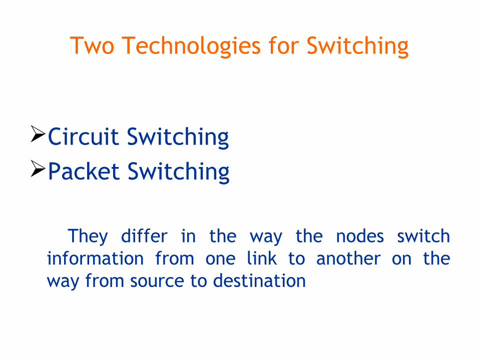
Two Technologies for Switching
Circuit SwitchingPacket Switching
They differ in the way the nodes switch information from one link to another on the way from source to destination

Circuit Switching
A dedicated communication path between the hosts

A
17
2
5
3
4
6
B
C D
E
F
Switching NodesEnd Hosts

Three Phases Circuit Establishment
• Host-B send a connection request towards Host-D• Intermediate nodes route the request to Host-D based
on measures of availability and cost• If ready, D accepts the connection and a dedicated path
(generally full duplex) is established from B through the intermediate nodes to D
Data Transfer• The data (analog/digital) is carried on the dedicated
path
Circuit Disconnect• Done by any one station• Signals are propagated to intermediate nodes to de-
allocate the dedicated resources

Principles
• Circuit switching designed for voice– Resources dedicated to a particular call– Much of the time a data connection is idle– Data rate is fixed
• Both ends must operate at the same rate

Packet Switching

Problems in Circuit Switching
Circuit Switching approach is inefficient
Since data rate is constant, therefore the devices interconnected must transmit and receive at the same data rate, This limits the interconnection of variety of hosts
Further calls are blocked when all the lines are busy

Packet Switching…...A quick overview
Data is transmitted in short packets
If a source has larger message to send, the message is broken up into a series of packets
Each packet contains user’s data plus some control information (header)
The control information, at a minimum includes the information that the network requires to be able to route the packet through the network and deliver it to the intended destination
At each node the packet is received, stored briefly and passed on to the next node

Advantages
Line efficiency is greater
A packet switching network can perform data rate conversion
In Circuit Switching, calls are blocked whereas in P.S. packets are still accepted but delivery delay increases
Priorities can be used, thus a higher priority packet experiences less delay

Types of Packet Switching
Datagram ApproachVirtual Circuit Approach

Datagram Packet Switching
Each packet is treated independently, with no reference to packets that have gone before
Each packet contains the address of its destination
The packets with the same destination do not always follow the same route
Some packets can get late and some can get destroyed in the network
Therefore, packets can be received out of order at the destination
There must be some mechanism of re-ordering at the receiver
Each packet, treated independently, is referred to as datagram

A
B

Virtual Circuit Packet Switching
A preplanned route is established before any packets are sent
All the packets follow that routeJust like circuit switching, the route
should be terminated after the transmission of data

DisconnectData
Connect Accept

Packets will be received in orderHowever, packets can get lost on the way

Event Timing