multiport multichannel analyzer - msudepni.sinp.msu.ru/~hatta/canberra/multiport multichannel...
TRANSCRIPT

MultiportMultichannel Analyzer
User’s Manual9231564B 7/00

Copyright 2000, Packard BioScience Company. All rights reserved.
The material in this manual, including all information, pictures,
graphics and text, is the property of Packard BioScience Company
and is protected by U.S. copyright laws and international copyright
conventions. No material in this manual may be reproduced,
published, translated, distributed or displayed by any means without
written permission from Canberra Industries, a division of Packard
BioScience Company.
The information in this manual describes the product as accurately as
possible, but is subject to change without notice.
Printed in the United States of America.
Canberra Industries, 800 Research Parkway, Meriden, CT 06450Tel: 203-238-2351 FAX: 203-235-1347 http://www.canberra.com
Table of Contents
1. Introduction . . . . . . . . . . . . . . . . . . . . . . . . . . . . . 1
Model MPT-EXE Multiport, External ADC Version . . . . . . . . . . . . . . . . . . . . . . . . 1
Models MPT-8E and MPT-16E Multiport, Internal ADC Versions. . . . . . . . . . . . . . . . . 2
Software Support. . . . . . . . . . . . . . . . . . . . . . . . . . . . . . . . . . . . . . . . . . . 2
2. Controls and Connectors . . . . . . . . . . . . . . . . . . . . . . 3
Front Panel . . . . . . . . . . . . . . . . . . . . . . . . . . . . . . . . . . . . . . . . . . . . . . 3
Rear Panel . . . . . . . . . . . . . . . . . . . . . . . . . . . . . . . . . . . . . . . . . . . . . . 4
3. Setup and Configuration . . . . . . . . . . . . . . . . . . . . . . 5
Installation . . . . . . . . . . . . . . . . . . . . . . . . . . . . . . . . . . . . . . . . . . . . . . 5
Connecting the System. . . . . . . . . . . . . . . . . . . . . . . . . . . . . . . . . . . . . . . . 5
Creating an MCA Input Definition . . . . . . . . . . . . . . . . . . . . . . . . . . . . . . . . . 6
The MID Wizard . . . . . . . . . . . . . . . . . . . . . . . . . . . . . . . . . . . . . . . . . . . 6
The MCA Input Definition Editor . . . . . . . . . . . . . . . . . . . . . . . . . . . . . . . . . . 8
The MCA Adjust Screens . . . . . . . . . . . . . . . . . . . . . . . . . . . . . . . . . . . . . . 8
Stabilizer Parameters . . . . . . . . . . . . . . . . . . . . . . . . . . . . . . . . . . . . . . 9
MCS Parameters . . . . . . . . . . . . . . . . . . . . . . . . . . . . . . . . . . . . . . . . 11
ADC . . . . . . . . . . . . . . . . . . . . . . . . . . . . . . . . . . . . . . . . . . . . . . 11
Acquire Setup Screen. . . . . . . . . . . . . . . . . . . . . . . . . . . . . . . . . . . . . . . . 12
4. Operation . . . . . . . . . . . . . . . . . . . . . . . . . . . . . . 13
Basic Spectroscopy Operations. . . . . . . . . . . . . . . . . . . . . . . . . . . . . . . . . . . 13
Gate. . . . . . . . . . . . . . . . . . . . . . . . . . . . . . . . . . . . . . . . . . . . . . . 13
External/Internal Sync . . . . . . . . . . . . . . . . . . . . . . . . . . . . . . . . . . . . . 13
MCS Mode . . . . . . . . . . . . . . . . . . . . . . . . . . . . . . . . . . . . . . . . . . . 14
Digital Spectrum Stabilizer Operation . . . . . . . . . . . . . . . . . . . . . . . . . . . . . 14
A. Specifications. . . . . . . . . . . . . . . . . . . . . . . . . . . . 15
Inputs . . . . . . . . . . . . . . . . . . . . . . . . . . . . . . . . . . . . . . . . . . . . . . . . 15
Outputs . . . . . . . . . . . . . . . . . . . . . . . . . . . . . . . . . . . . . . . . . . . . . . . 15
Controls . . . . . . . . . . . . . . . . . . . . . . . . . . . . . . . . . . . . . . . . . . . . . . . 16
Indicators . . . . . . . . . . . . . . . . . . . . . . . . . . . . . . . . . . . . . . . . . . . . . . 16
Processor . . . . . . . . . . . . . . . . . . . . . . . . . . . . . . . . . . . . . . . . . . . . . . 16
Data Acquisition . . . . . . . . . . . . . . . . . . . . . . . . . . . . . . . . . . . . . . . . . . 16
ADC . . . . . . . . . . . . . . . . . . . . . . . . . . . . . . . . . . . . . . . . . . . . . . . . 16
MCS . . . . . . . . . . . . . . . . . . . . . . . . . . . . . . . . . . . . . . . . . . . . . . . . 17
Live Time Clock . . . . . . . . . . . . . . . . . . . . . . . . . . . . . . . . . . . . . . . . . . 17
Presets . . . . . . . . . . . . . . . . . . . . . . . . . . . . . . . . . . . . . . . . . . . . . . . 18
SCA. . . . . . . . . . . . . . . . . . . . . . . . . . . . . . . . . . . . . . . . . . . . . . . . . 18
Digital Stabilizer . . . . . . . . . . . . . . . . . . . . . . . . . . . . . . . . . . . . . . . . . . 18
External ADC. . . . . . . . . . . . . . . . . . . . . . . . . . . . . . . . . . . . . . . . . . . . 18
System Requirements. . . . . . . . . . . . . . . . . . . . . . . . . . . . . . . . . . . . . . . . 18
Power Requirements . . . . . . . . . . . . . . . . . . . . . . . . . . . . . . . . . . . . . . . . 19
Physical . . . . . . . . . . . . . . . . . . . . . . . . . . . . . . . . . . . . . . . . . . . . . . . 19
Environmental . . . . . . . . . . . . . . . . . . . . . . . . . . . . . . . . . . . . . . . . . . . 19
Ordering Information . . . . . . . . . . . . . . . . . . . . . . . . . . . . . . . . . . . . . . . . 19
B. Installation and Controls. . . . . . . . . . . . . . . . . . . . . . 20
Installling the GPIB (IEEE-488) Card . . . . . . . . . . . . . . . . . . . . . . . . . . . . . . .20
Setting the Multiport’s GPIB Address . . . . . . . . . . . . . . . . . . . . . . . . . . . . . . .21
Setting the Internal Controls . . . . . . . . . . . . . . . . . . . . . . . . . . . . . . . . . . . . 22
Main Board Controls . . . . . . . . . . . . . . . . . . . . . . . . . . . . . . . . . . . . . . 22
ADC Board Controls . . . . . . . . . . . . . . . . . . . . . . . . . . . . . . . . . . . . . . 23
3. Rear Panel Connector Pinouts . . . . . . . . . . . . . . . . . . 25
I/O Connector. . . . . . . . . . . . . . . . . . . . . . . . . . . . . . . . . . . . . . . . . . . . 25
DMR Connector . . . . . . . . . . . . . . . . . . . . . . . . . . . . . . . . . . . . . . . . . . 26
IEEE-488 Connector . . . . . . . . . . . . . . . . . . . . . . . . . . . . . . . . . . . . . . . . 27
ii

1. Introduction
The Multiport MCA meets the need for a cost effective, mid-performance, general pur-pose Multichannel Analyzer. Packaged in a convenient, double wide NIM module, theMultiport is available in three versions – 8K and 16K units with internal ADC and a16K version for use with an external Canberra ADC.
Host computer interfacing is accomplished via an industry standard IEEE-488 parallelinterface. The widely accepted IEEE-488 interface makes the Multiport compatiblewith a wide variety of computer platforms. IEEE-488 interface boards are available inISA, EISA and PCI bus form factors – so the Multiport user need not worry aboutcompatibility as computer bus standards evolve. Also, up to 15 Multiport units can becontrolled from a single IEEE interface, so a Multiport system does not consume morethan a single PC slot. By keeping all sensitive components out of the computer itself,Multiport provides better performance and lower noise than plug-in card based MCAs– but at comparable prices.
Multiport is suitable for use with a wide range of radiation detectors. Selecting aproper preamplifier, amplifier and high voltage power supply, makes Multiport com-patible with NaI(Tl), HPGe, SiLi, CdTe, Ion Implanted, Plastic scintillation, BGO andother detector technologies. Modular NIM packaging makes it easy to reconfigure sys-tems as needs change or as new technologies become available.
A two point digital stabilizer is included to ensure system stability under a range ofcount rates and temperature variations. Gain and zero stabilization are independentlycontrolled to lock on high and low energy peaks (respectively) in the spectrum. Sepa-rate ranges for HPGe and NaI detectors ensure that stabilizer will operate correctlywith either detector type.
For added flexibility, the Multiport supports both pulse height analysis (PHA) andmultichannel scaling (MCS) modes of operation. In MCS mode, a single channel ana-lyzer (SCA) output is enabled as well as a SYNC input that allows acquisition to besynchronized by external apparatus. Input rates of up to 10 MHz are supported.
Model MPT-EXE Multiport, External ADC VersionFor applications requiring “no compromises” performance in terms of count rate, reso-lution and temperature stability, the Multiport can be paired with a Model 2060 DigitalSignal Processor (DSP). For applications where requirements are not as stringent, butwhere high performance ADCs are still desirable, choose the Model 8701 WilkinsonADC or the high speed Models 8713 or 8715 fixed dead time ADCs.

Models MPT-8E and MPT-16E Multiport, Internal ADCVersions
Where the convenience of an internal ADC is preferred, the Multiport can be obtainedin versions with integral 8K or 16K ADC. The internal ADC is a fully buffered unitwith a fixed dead time of 8 µs. Conversion gain can be set to 16K (MPT-16E only),8K, 4K, 2K, 1K, 512 or 256 channels. Analog input connections may be made througheither front or rear panel BNC connections.
Software SupportThe Multiport is fully supported by Canberra’s trend setting Genie-2000 softwareproduct family. Genie-2000 supports a wide range of time proven spectral analysis al-gorithms, modern spectrum display and user interface as well as a variety of specialapplications programs. Genie-2000 software solutions are available for applicationsranging as widely as laboratory gamma and alpha spectroscopy, waste measurement,whole body counting and nuclear safeguards.
2
Introduction
3
Front Panel
2. Controls and Connectors
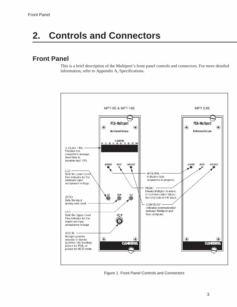
Front PanelThis is a brief description of the Multiport’s front panel controls and connectors. For more detailedinformation, refer to Appendix A, Specifications.
Figure 1 Front Panel Controls and Connectors
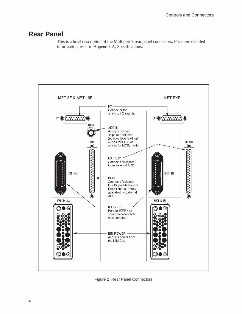
Rear PanelThis is a brief description of the Multiport’s rear panel connectors. For more detailedinformation, refer to Appendix A, Specifications.
4
Controls and Connectors
Figure 2 Rear Panel Connectors
3. Setup and Configuration
This chapter will guide you through to connecting and setting up the system.
InstallationThe Canberra Model 2100 Bin and Power Supply, or other bin and power supply sys-tems conforming to the mechanical and electrical standards set by DOE/ER-00457Twill accommodate the Multiport MCA. The module’s right side cover acts as a guidefor insertion of the instrument. The module is secured by turning the two front panelcaptive screws clockwise until finger tight. It is recommended that the NIM bin powerswitch be OFF whenever the module is installed or removed. To ensure safety, be sureto use a NIM Bin which complies with all applicable safety requirements.
The Multiport can be operated where the ambient air temperature is between 0°C and+50°C (+120°F maximum). Perforations in the top and bottom sides permit cooling airto circulate through the module. When relay rack mounted along with other heat gen-erating equipment, adequate clearance should be provided to allow for sufficient airflow through both the perforated top and bottom covers of the NIM Bin.
Connecting the SystemUsing the supplied cable, connect the GPIB interface cable to the Multiport’sIEEE-488 interface port, and the other end of the cable to the interface port of the HostComputer’s GPIB card. This provides the communication between Multiport and thehost computer. For field installation instructions for the Multiport board, refer toAppendix B, Installing the IEEE-488 Board, on page 20.
Model MPT-EXEConnect the supplied ribbon cable between the external ADC’s DATA connector tothe MPT-EXE’s EXT ADC connnector (PB-37).
Models MPT-8E and MPT-16EConnect a standard BNC cable between the Multiport’s ADC IN connector and theamplifier’s Output signal connector. This provides the signal from the amplifier to theMultiport’s internal ADC. Note that this connector is not used with the ModelMPT-EXE Multiport, which uses an external ADC.
DMRCurrently the Multiport does not support a Digital Multiplexer/Router (DMR).
5
Setup and Configuration
I/OOptional external signals on this port are connected through the supplied 14−leadcable. Each lead is labeled. Descriptions of these signals can be found under Inputsand Outputs in Appendix A, Specifications, on page 15.
Creating an MCA Input DefinitionAfter you’ve installed the Genie-2000 software, the first step in using your Multiport isto create an MCA Input Definition (MID).
MID Wizard or MID Editor?For most cases, you’ll use the MID Wizard to help you set up your Multiport’s InputDefinition quickly and easily.
If your Input Definition is more complex than the MID Wizard was designed to han-dle, you’ll use the MID Editor (page 8) to create or change your definition.
The MID WizardTo use the MID Wizard, open the Genie-2000 folder and select the MID Wizard iconto start the definition process.
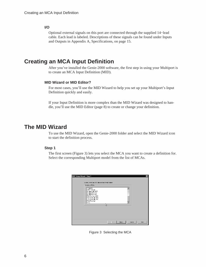
Step 1The first screen (Figure 3) lets you select the MCA you want to create a definition for.Select the corresponding Multiport model from the list of MCAs.
6
Creating an MCA Input Definition
Figure 3 Selecting the MCA
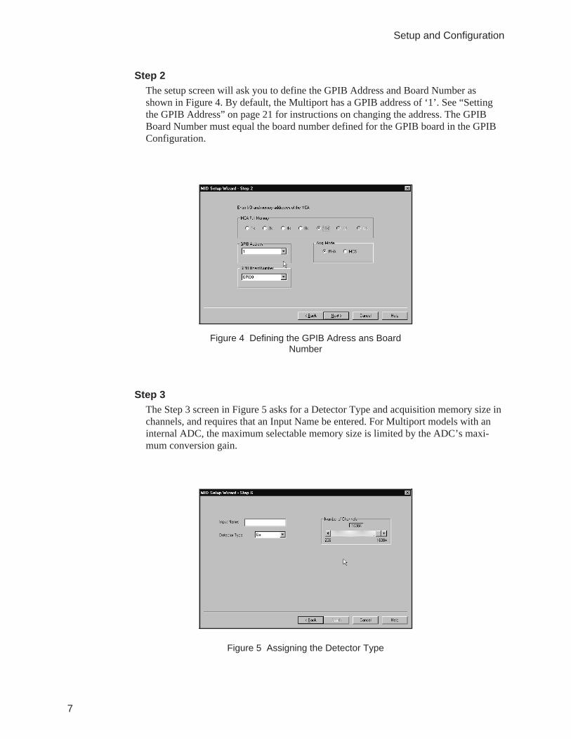
Step 2The setup screen will ask you to define the GPIB Address and Board Number asshown in Figure 4. By default, the Multiport has a GPIB address of ‘1’. See “Settingthe GPIB Address” on page 21 for instructions on changing the address. The GPIBBoard Number must equal the board number defined for the GPIB board in the GPIBConfiguration.
Step 3The Step 3 screen in Figure 5 asks for a Detector Type and acquisition memory size inchannels, and requires that an Input Name be entered. For Multiport models with aninternal ADC, the maximum selectable memory size is limited by the ADC’s maxi-mum conversion gain.
7
Setup and Configuration
Figure 4 Defining the GPIB Adress ans BoardNumber
Figure 5 Assigning the Detector Type

Ending the DefinitionTo complete your Input Definition, selectFinish. The input that you just defined willbe stored as an MID file namedinputname.MID and automatically loaded into theGenie-2000’s MCA Runtime Configuration Database (described in “Using MCA Defi-nition Tables” in Chapter 3, MCA Input Definition of theGenie-2000 OperationsManual). When you selectFinish, you will be asked if you would like to define an-other input. Answering No will close the Wizard.
Note that if you didn’t enter an Input Name, you won’t be allowed to exit the Step 3screen. If the name you entered is the same as the name of an existing MID file, thesystem will tell you so and go back to Step 3 to let you enter another name.
The MCA Input Definition EditorMost users will not need to use the MCA Input Definition (MID) Editor. The MID Ed-itor allows you to create, edit and manage input definitions. However, for most users,the facilities provided in the MID Wizard are sufficient. You’ll have to use the MIDEditor only if you want to change any of the parameters listed below from their defaultvalues:
• Dwell Time for MCS mode. Note that this parameter is also adjustable withinthe Gamma Acquisition and Analysis application.
• Coincidence Mode and Dead Time Mode for the Models MPT-8E andMPT-16E with internal ADC.
• Multiple Memory Groups are selectable only from within the MID Editor.
The editing procedure is described in “Editing an MCA Definition” in the MCA InputDefinition chapter of theGenie-2000 Operations Manual. That chapter also has de-tailed information on using the MID Editor.
The MCA Adjust ScreensThe MCA Adjust Screens, which are accessed from the Gamma Acquisition andAnalysis application’s Menu Bar, allow you to adjust the Multiport’s programmablecontrols.
As adjustments are made in the dialog box, the new values are sent to the Multiport.To save the adjustments to the datasource’s CAM file, use the Gamma Acquisition andAnalysis application’sFile | Savecommand so that the next time this datasource is se-lected, the proper setting will be loaded into the Multiport.
8
The MCA Input Definition Editor
TheNext andPrev(ious) buttons at the left side of the Adjust screen are used to moveto the next (or previous) “page” of the controls when there are more control elementsthan will fit in the basic box.
To access the Adjust screens, a Multiport datasource must have been opened. To open,selectFile | Open Datasource,then select “Detector” in the Type box. Next, select thedatasource file and click on open.
Note: If you get a “Required Hardware Unavailable” error, possible causesare: selecting the wrong datasource for the instrument, a problemwith the IEEE-488 communication interface (check the cable), or theNIM Bin power is off.
If you get a “Hardware Verification Error” there is a mismatch be-tween the MID Definition setup and the hardware configuration. Youcan choose to accept or not accept the verification error in the associ-ated dialog box. If you select NO, a RED error box will appear in thetop left corner of the Gamma Acquisition and Analysis window. Todetermine the source of the verification error, open the Status Pageby clicking MCA | Status in the Acquisition and Analysis window. Theproblematic item will be marked with an asterisk (*).
Each of the following sections describes one of the Multiport parameters that can bechanged in the Gamma Acquisition and Analysis (GAA) application’s Adjust dialog.To change a parameter, click onMCA | Adjust in the GAA application’s Main Menu,then select the radio button for the parameter you want to change.
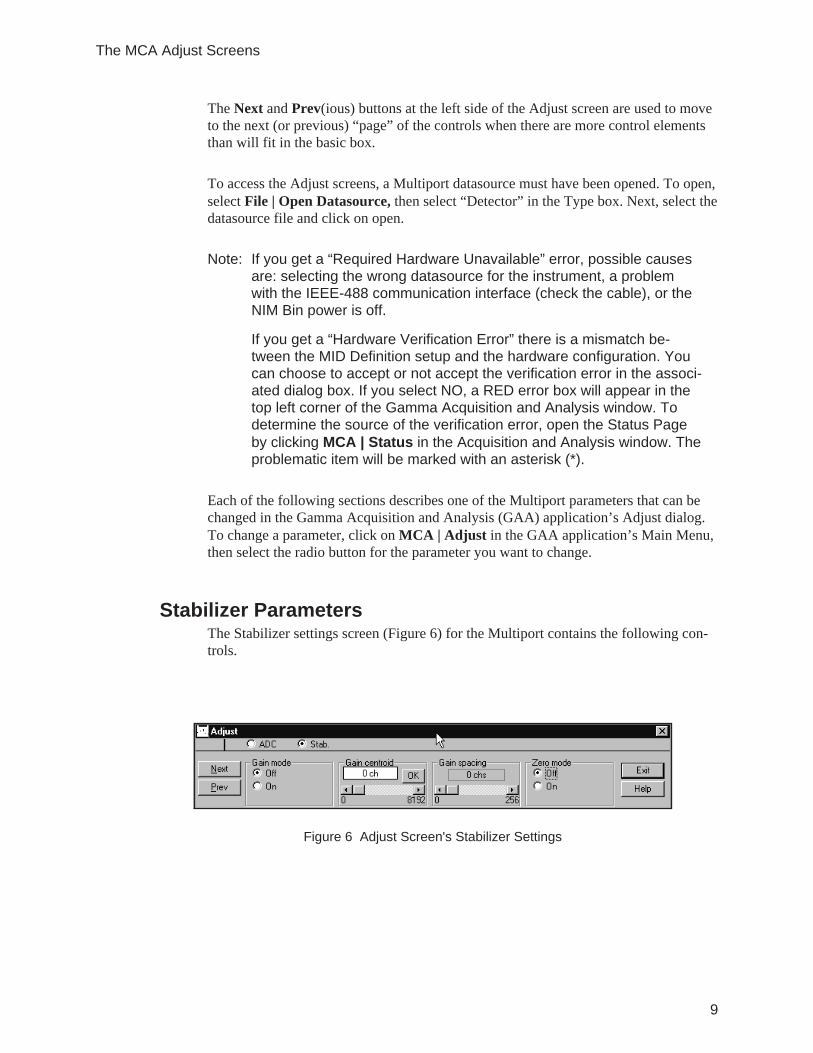
Stabilizer ParametersThe Stabilizer settings screen (Figure 6) for the Multiport contains the following con-trols.
9
The MCA Adjust Screens
Figure 6 Adjust Screen's Stabilizer Settings
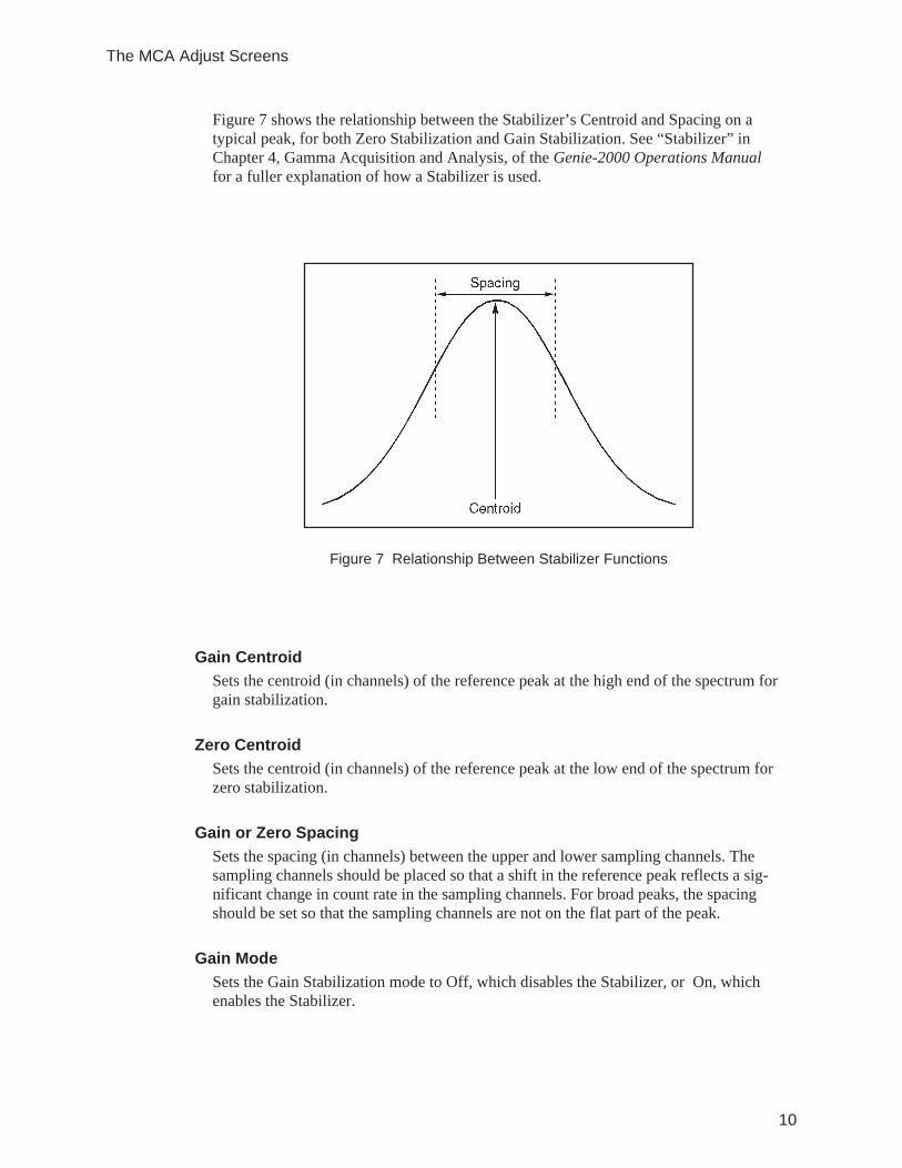
Figure 7 shows the relationship between the Stabilizer’s Centroid and Spacing on atypical peak, for both Zero Stabilization and Gain Stabilization. See “Stabilizer” inChapter 4, Gamma Acquisition and Analysis, of theGenie-2000 Operations Manualfor a fuller explanation of how a Stabilizer is used.
Gain CentroidSets the centroid (in channels) of the reference peak at the high end of the spectrum forgain stabilization.
Zero CentroidSets the centroid (in channels) of the reference peak at the low end of the spectrum forzero stabilization.
Gain or Zero SpacingSets the spacing (in channels) between the upper and lower sampling channels. Thesampling channels should be placed so that a shift in the reference peak reflects a sig-nificant change in count rate in the sampling channels. For broad peaks, the spacingshould be set so that the sampling channels are not on the flat part of the peak.
Gain ModeSets the Gain Stabilization mode to Off, which disables the Stabilizer, or On, whichenables the Stabilizer.
10
The MCA Adjust Screens
Figure 7 Relationship Between Stabilizer Functions
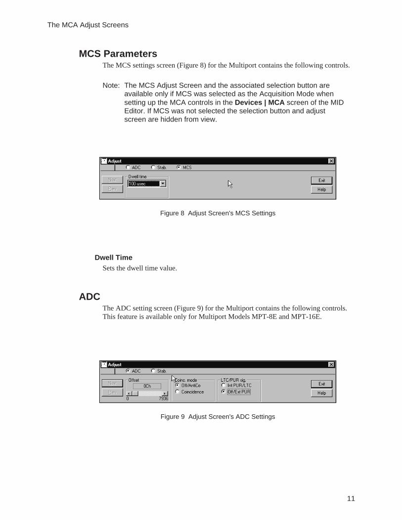
MCS ParametersThe MCS settings screen (Figure 8) for the Multiport contains the following controls.
Note: The MCS Adjust Screen and the associated selection button areavailable only if MCS was selected as the Acquisition Mode whensetting up the MCA controls in the Devices | MCA screen of the MIDEditor. If MCS was not selected the selection button and adjustscreen are hidden from view.
Dwell TimeSets the dwell time value.
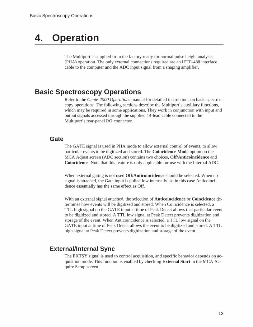
ADCThe ADC setting screen (Figure 9) for the Multiport contains the following controls.This feature is available only for Multiport Models MPT-8E and MPT-16E.
11
The MCA Adjust Screens
Figure 8 Adjust Screen's MCS Settings
Figure 9 Adjust Screen's ADC Settings

OffsetSets the ADC’s digital offset, in channels.
Coincidence ModeSets the coincidence mode for the extended Gate signal, when external gating is used.
Acquire Setup ScreenThe Gamma Acquisition and Analysis application’s Acquire Setup Screen is describedin detail in theGenie-2000 Operations Manual. However, the External Start option onthis screen is of particular significance at this time.
Checking External Start enables Multiport’s External Sync function, which works inconjunction with the EXTSY signal at the rear panel I/O port. In PHA mode, a positiveTTL level enables data acquisition and the Real Time and Live Time clocks. In MCSmode, a positive TTL pulse starts/restarts a sweep.
12
Setup and Configuration
4. Operation
The Multiport is supplied from the factory ready for normal pulse height analysis(PHA) operation. The only external connections required are an IEEE-488 interfacecable to the computer and the ADC input signal from a shaping amplifier.
Basic Spectroscopy OperationsRefer to theGenie-2000 Operationsmanual for detailed instructions on basic spectros-copy operations. The following sections describe the Multiport’s auxiliary functions,which may be required in some applications. They work in conjunction with input andoutput signals accessed through the supplied 14-lead cable connected to theMultiport’s rear-panelI/O connector.
GateThe GATE signal is used in PHA mode to allow external control of events, to allowparticular events to be digitized and stored. TheCoincidence Modeoption on theMCA Adjust screen (ADC section) contains two choices,Off/Anticoincidence andCoincidence. Note that this feature is only applicable for use with the Internal ADC.
When external gating is not usedOff/Anticoincidence should be selected. When nosignal is attached, the Gate input is pulled low internally, so in this case Anticoinci-dence essentially has the same effect as Off.
With an external signal attached, the selection ofAnticoincidenceor Coincidencede-termines how events will be digitized and stored. When Coincidence is selected, aTTL high signal on the GATE input at time of Peak Detect allows that particular eventto be digitized and stored. A TTL low signal at Peak Detect prevents digitization andstorage of the event. When Anticoincidence is selected, a TTL low signal on theGATE input at time of Peak Detect allows the event to be digitized and stored. A TTLhigh signal at Peak Detect prevents digitization and storage of the event.
External/Internal SyncThe EXTSY signal is used to control acquisition, and specific behavior depends on ac-quisition mode. This function is enabled by checkingExternal Start in the MCA Ac-quire Setup screen.
13
Basic Spectroscopy Operations
PHA ModeIn PHA mode, Data Acquisition must be started first by clicking the Acquire Startbutton. Then a positive TTL Level applied to the EXTSY connector enables data ac-quisition and RealTime and LiveTime clocks. Note that the EXTSY Input is pulledhigh internally when no signal is attached, which has the same effect (enable) as a highTTL input signal.
MCS ModeIn MCS mode, Data Acquisition must be started first as well. Then a positive TTLpulse applied to the EXTSY connector starts the next sweep. When no signal is at-tached, MCS sweeps will stop since the sweeps are triggered on pulse edges.
MCS ModeInput events are collected through the MCS connector in the form of positive TTLpulses. To demonstrate the MCS operation, connect the SCA connector to the MCSconnector with a short length of BNC coaxial cable. This connects the SCA output sig-nal from the internal ADC to the MCS input. You can set the desired MCS DwellTime in the MCA Adjust screen (page 8).
Digital Spectrum Stabilizer OperationThe Digital Spectrum Stabilizer is adjusted in the MCA Adjust screen (page 8). It cor-rects for drift in either high resolution Germanium Detectors or a low resolution NaIDetectors. This feature is available only for Multiport Models MPT-8E and MPT-16E.You can choose to correct zero shift, gain shift, or both. Using a two-point stabiliza-tion method, a high energy peak is monitored for gain drift and a low energy peak ismonitored for zero drift. The effective gain and zero intercepts of the ADC are ad-justed to compensate for drift.
14
Operation
A. Specifications
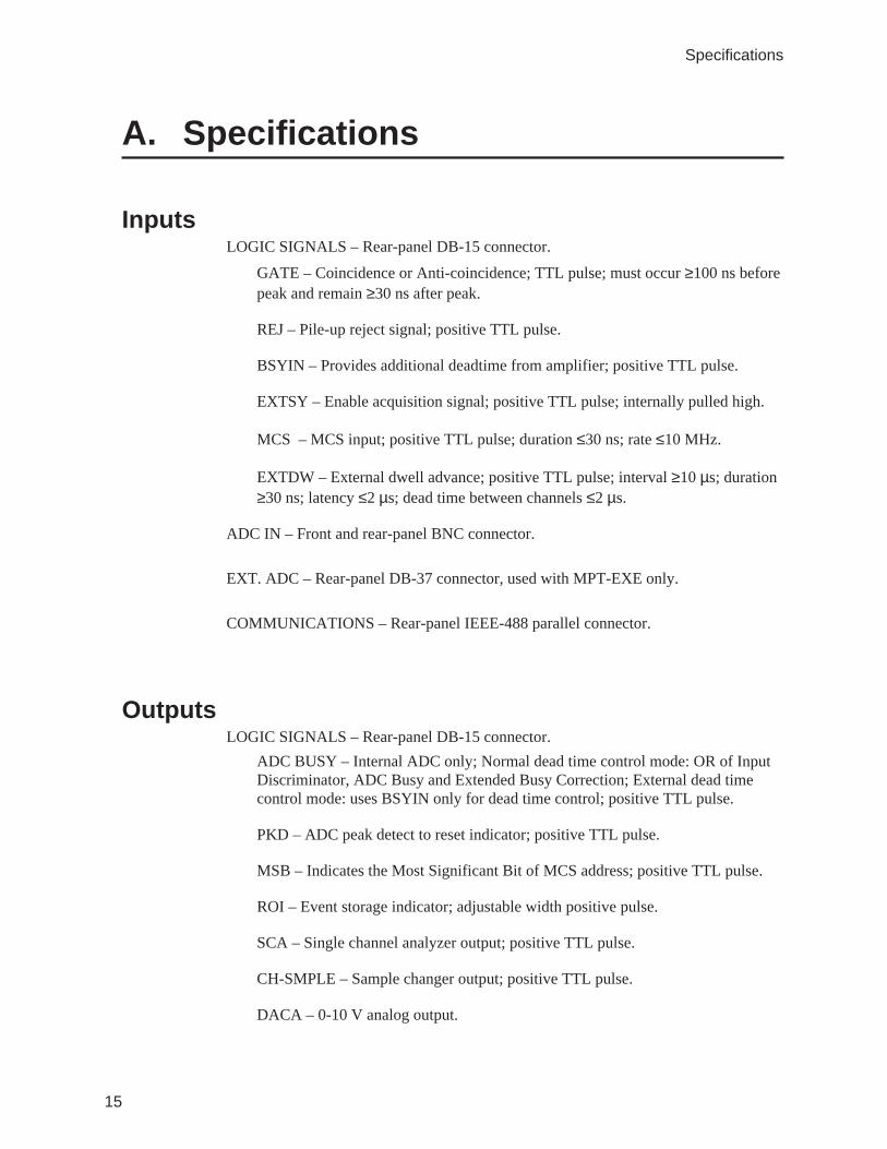
InputsLOGIC SIGNALS – Rear-panel DB-15 connector.
GATE – Coincidence or Anti-coincidence; TTL pulse; must occur≥100 ns beforepeak and remain≥30 ns after peak.
REJ – Pile-up reject signal; positive TTL pulse.
BSYIN – Provides additional deadtime from amplifier; positive TTL pulse.
EXTSY – Enable acquisition signal; positive TTL pulse; internally pulled high.
MCS – MCS input; positive TTL pulse; duration≤30 ns; rate≤10 MHz.
EXTDW – External dwell advance; positive TTL pulse; interval≥10 µs; duration≥30 ns; latency≤2 µs; dead time between channels≤2 µs.
ADC IN – Front and rear-panel BNC connector.
EXT. ADC – Rear-panel DB-37 connector, used with MPT-EXE only.
COMMUNICATIONS – Rear-panel IEEE-488 parallel connector.
OutputsLOGIC SIGNALS – Rear-panel DB-15 connector.
ADC BUSY – Internal ADC only; Normal dead time control mode: OR of InputDiscriminator, ADC Busy and Extended Busy Correction; External dead timecontrol mode: uses BSYIN only for dead time control; positive TTL pulse.
PKD – ADC peak detect to reset indicator; positive TTL pulse.
MSB – Indicates the Most Significant Bit of MCS address; positive TTL pulse.
ROI – Event storage indicator; adjustable width positive pulse.
SCA – Single channel analyzer output; positive TTL pulse.
CH-SMPLE – Sample changer output; positive TTL pulse.
DACA – 0-10 V analog output.
15
Specifications

DACB – 0-10 V analog output.
ControlsRESET – Front panel pushbutton.
IndicatorsDT METER – Ten-segment front-panel multicolor-LED bar graph.
ACQUIRE LED – Front-panel LED.
COMM BUSY – Front-panel LED.
ProcessorIntel 80C188; 10 MHz clock.
ROM – 128K x 8.
RAM – 64K x 8 data RAM, 32K x 8 processor RAM.
Data AcquisitionCHANNELS – 16 384; configurable into input sizes of 8192, 4096, 2048, 1024, 512 or256 channels.
ADCCONVERSION RATE – Fully buffered, 16 382 channel, successive approximation, 8µs ADC.
CONVERSION GAIN – 16K, 8K, 4K, 2K, 1K, 512, 256; computer selectable.
RANGE – From 0 to 10 V, unipolar or bipolar, positive lobe leading.
16
Specifications
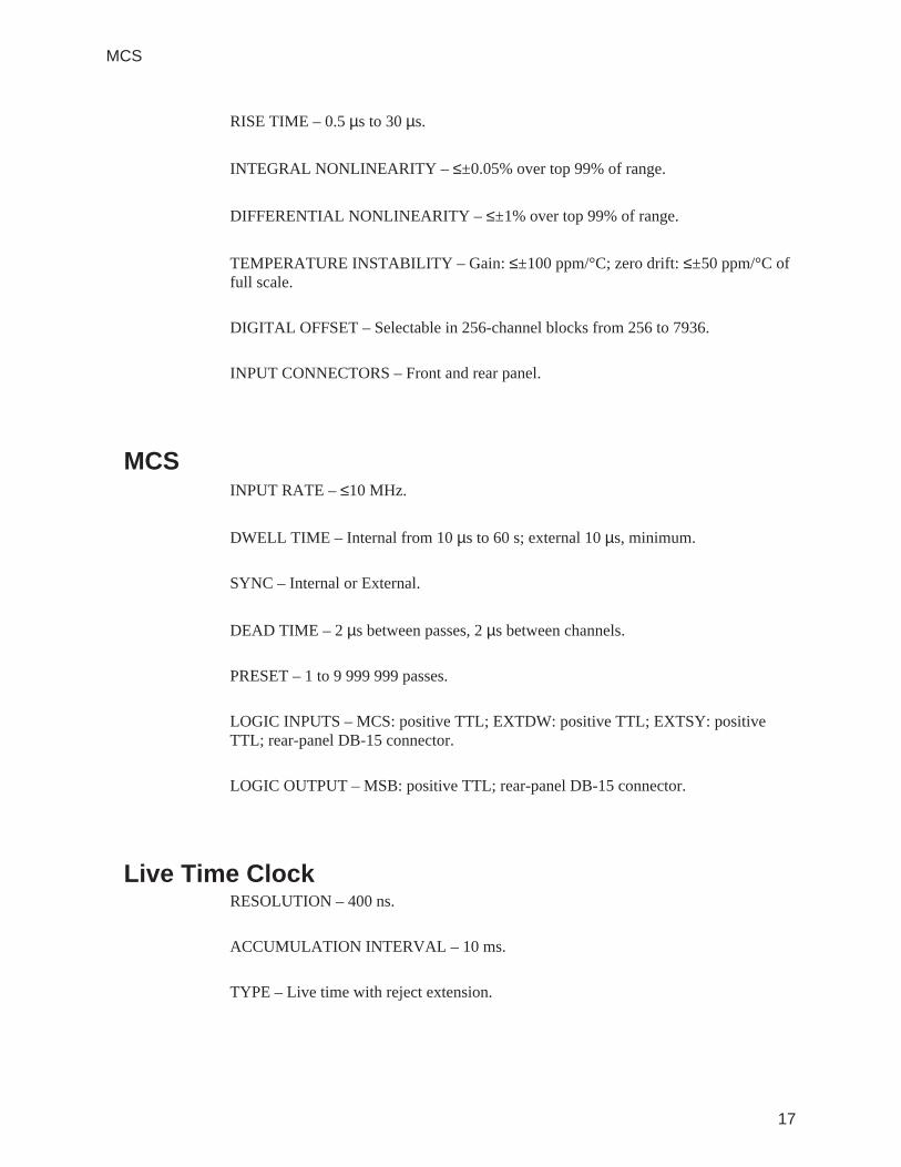
RISE TIME – 0.5µs to 30µs.
INTEGRAL NONLINEARITY – ≤±0.05% over top 99% of range.
DIFFERENTIAL NONLINEARITY – ≤±1% over top 99% of range.
TEMPERATURE INSTABILITY – Gain:≤±100 ppm/°C; zero drift:≤±50 ppm/°C offull scale.
DIGITAL OFFSET – Selectable in 256-channel blocks from 256 to 7936.
INPUT CONNECTORS – Front and rear panel.
MCSINPUT RATE –≤10 MHz.
DWELL TIME – Internal from 10µs to 60 s; external 10µs, minimum.
SYNC – Internal or External.
DEAD TIME – 2µs between passes, 2µs between channels.
PRESET – 1 to 9 999 999 passes.
LOGIC INPUTS – MCS: positive TTL; EXTDW: positive TTL; EXTSY: positiveTTL; rear-panel DB-15 connector.
LOGIC OUTPUT – MSB: positive TTL; rear-panel DB-15 connector.
Live Time ClockRESOLUTION – 400 ns.
ACCUMULATION INTERVAL – 10 ms.
TYPE – Live time with reject extension.
17
MCS
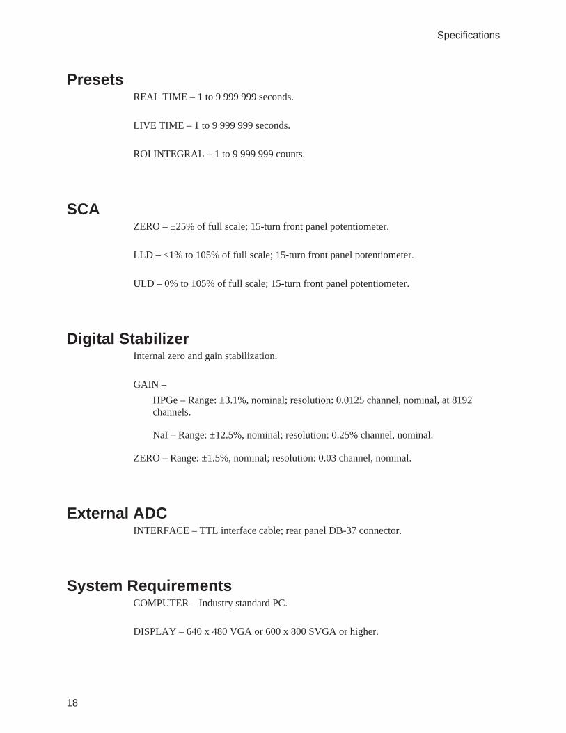
PresetsREAL TIME – 1 to 9 999 999 seconds.
LIVE TIME – 1 to 9 999 999 seconds.
ROI INTEGRAL – 1 to 9 999 999 counts.
SCAZERO – ±25% of full scale; 15-turn front panel potentiometer.
LLD – <1% to 105% of full scale; 15-turn front panel potentiometer.
ULD – 0% to 105% of full scale; 15-turn front panel potentiometer.
Digital StabilizerInternal zero and gain stabilization.
GAIN –
HPGe – Range: ±3.1%, nominal; resolution: 0.0125 channel, nominal, at 8192channels.
NaI – Range: ±12.5%, nominal; resolution: 0.25% channel, nominal.
ZERO – Range: ±1.5%, nominal; resolution: 0.03 channel, nominal.
External ADCINTERFACE – TTL interface cable; rear panel DB-37 connector.
System RequirementsCOMPUTER – Industry standard PC.
DISPLAY – 640 x 480 VGA or 600 x 800 SVGA or higher.
18
Specifications

Power Requirements+24 V dc – 30 mA +12 V dc – 26 mA
–24 V dc – 30 mA –12 V dc – 140 mA
Power consumption (120 V ac) 70 mA
PhysicalSIZE – Standard double-width NIM module 6.86 x 22.12 cm (2.70 x 8.71 in.) perDOE/ER-0457T.
NET WEIGHT – 1.7 kg (3.8 lb).
SHIPPING WEIGHT – 2.1 kg (4.6 lb).
EnvironmentalOPERATING TEMPERATURE – 0 to 50 °C.
OPERATING HUMIDITY – 0-80% relative, non-condensing.
Ordering InformationMPT-EXE – 16K Multiport for use with external Canberra ADC.
MPT-8E – 8K Multiport with internal 8 µs ADC.
MPT-16E – 16K Multiport with internal 8 µs ADC.
Requires Genie-2000 software, sold separately.
19
Power Requirements

B. Installation and Controls
Installling the GPIB (IEEE-488) CardThe GPIB (General Purpose Interface Bus) communication card and software may beinstalled in the host computer by using the procedures in the applicable National In-struments manual. National Instruments Model AT-GPIB/TNT and PCI-GPIB cardsare recommended, and are available from National Instruments or through Canberra.
Follow installation and configuration instructions in the corresponding GPIB Card in-stallation manual. In most cases the default configuration settings are sufficient. How-ever, the following settings will work. Note that not all GPIB card models will displayeach of these settings during configuration.
Switch Setting
Primary GPIB Address 0
Secondary GPIB Address None
Base I/O Address* —
Interrupt Request* —
DMA channel None
Bus Timing 500 ns
Cable Length for High-Speed Disabled
System Controller Yes
I/O Timeout 10 sec
Parallel Poll Duration Default
Enable Auto Serial Polling Yes
Enable CIC Protocol No
Assert REN when SC No
Terminate Read on EOS No
Set EOI with EOS on Write No
8-bit EOS Compare No
Send EOI at end of Write Yes
EOS byte 0
*The Base I/O Address and Interrupt Request (IRQ) arenot specified because they may have to be set individuallyfor existing hardware and software.
20
Installling the GPIB (IEEE-488) Card
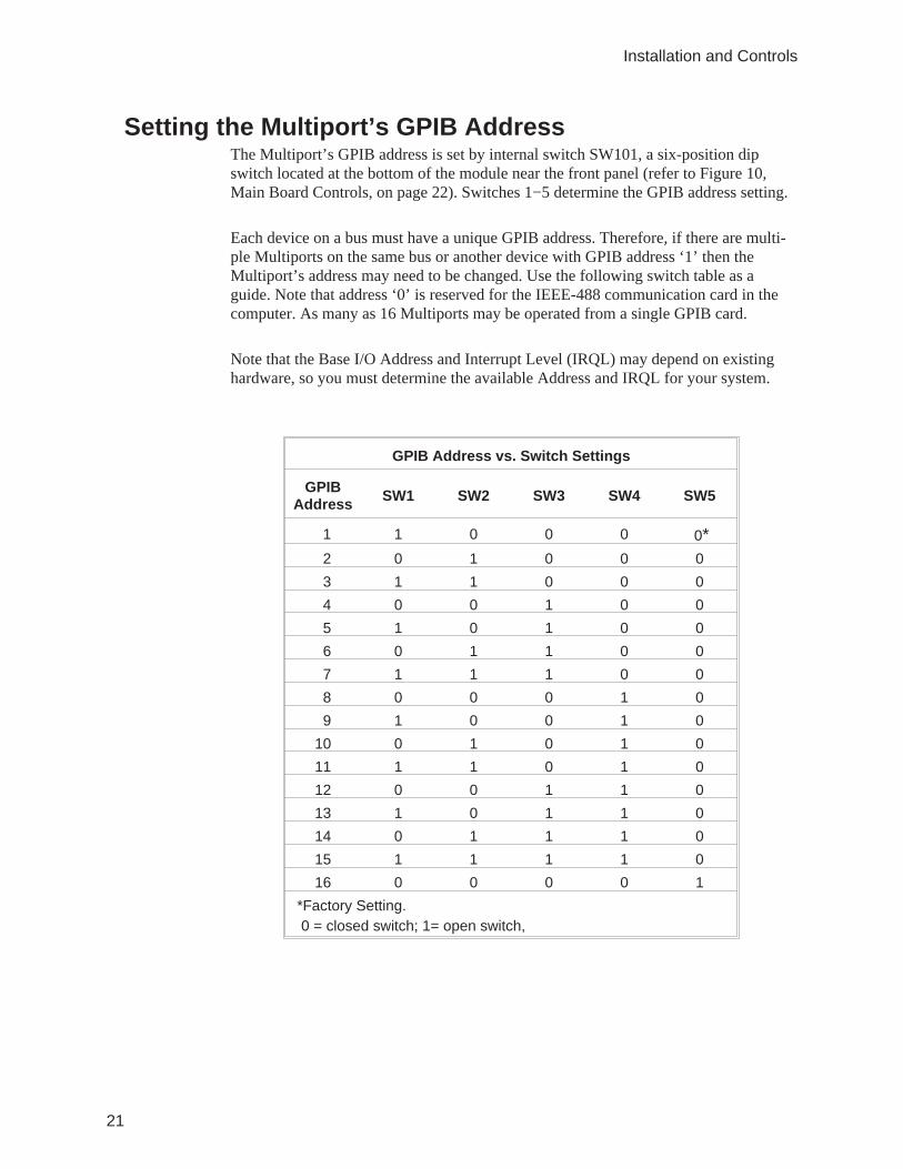
Setting the Multiport’s GPIB AddressThe Multiport’s GPIB address is set by internal switch SW101, a six-position dipswitch located at the bottom of the module near the front panel (refer to Figure 10,Main Board Controls, on page 22). Switches 1−5 determine the GPIB address setting.
Each device on a bus must have a unique GPIB address. Therefore, if there are multi-ple Multiports on the same bus or another device with GPIB address ‘1’ then theMultiport’s address may need to be changed. Use the following switch table as aguide. Note that address ‘0’ is reserved for the IEEE-488 communication card in thecomputer. As many as 16 Multiports may be operated from a single GPIB card.
Note that the Base I/O Address and Interrupt Level (IRQL) may depend on existinghardware, so you must determine the available Address and IRQL for your system.
GPIB Address vs. Switch Settings
GPIBAddress SW1 SW2 SW3 SW4 SW5
1 1 0 0 0 0*2 0 1 0 0 0
3 1 1 0 0 0
4 0 0 1 0 0
5 1 0 1 0 0
6 0 1 1 0 0
7 1 1 1 0 0
8 0 0 0 1 0
9 1 0 0 1 0
10 0 1 0 1 0
11 1 1 0 1 0
12 0 0 1 1 0
13 1 0 1 1 0
14 0 1 1 1 0
15 1 1 1 1 0
16 0 0 0 0 1
*Factory Setting.0 = closed switch; 1= open switch,
21
Installation and Controls
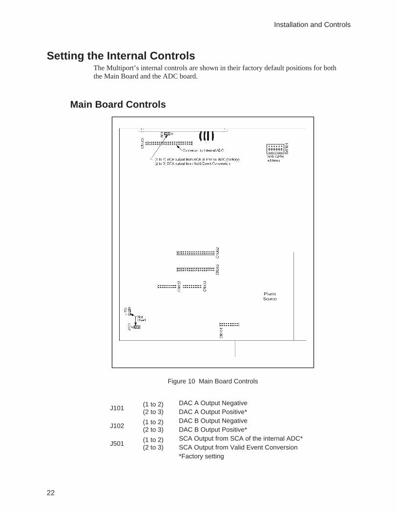
Setting the Internal ControlsThe Multiport’s internal controls are shown in their factory default positions for boththe Main Board and the ADC board.
Main Board Controls
J101(1 to 2)(2 to 3)
DAC A Output NegativeDAC A Output Positive*
J102(1 to 2)(2 to 3)
DAC B Output NegativeDAC B Output Positive*
J501(1 to 2)(2 to 3)
SCA Output from SCA of the internal ADC*SCA Output from Valid Event Conversion*Factory setting
22
Installation and Controls
Figure 10 Main Board Controls
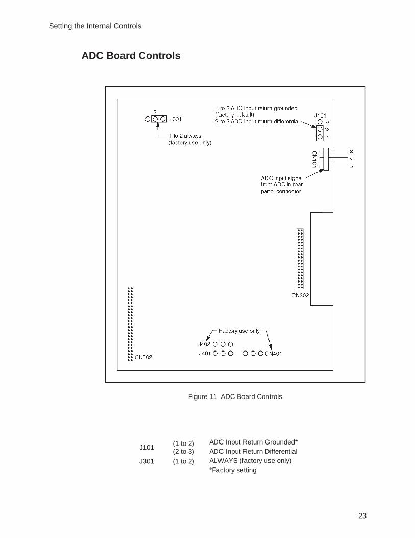
ADC Board Controls
J101(1 to 2)(2 to 3)
ADC Input Return Grounded*ADC Input Return Differential
J301 (1 to 2) ALWAYS (factory use only)*Factory setting
23
Setting the Internal Controls
Figure 11 ADC Board Controls
C. Rear Panel Connector Pinouts
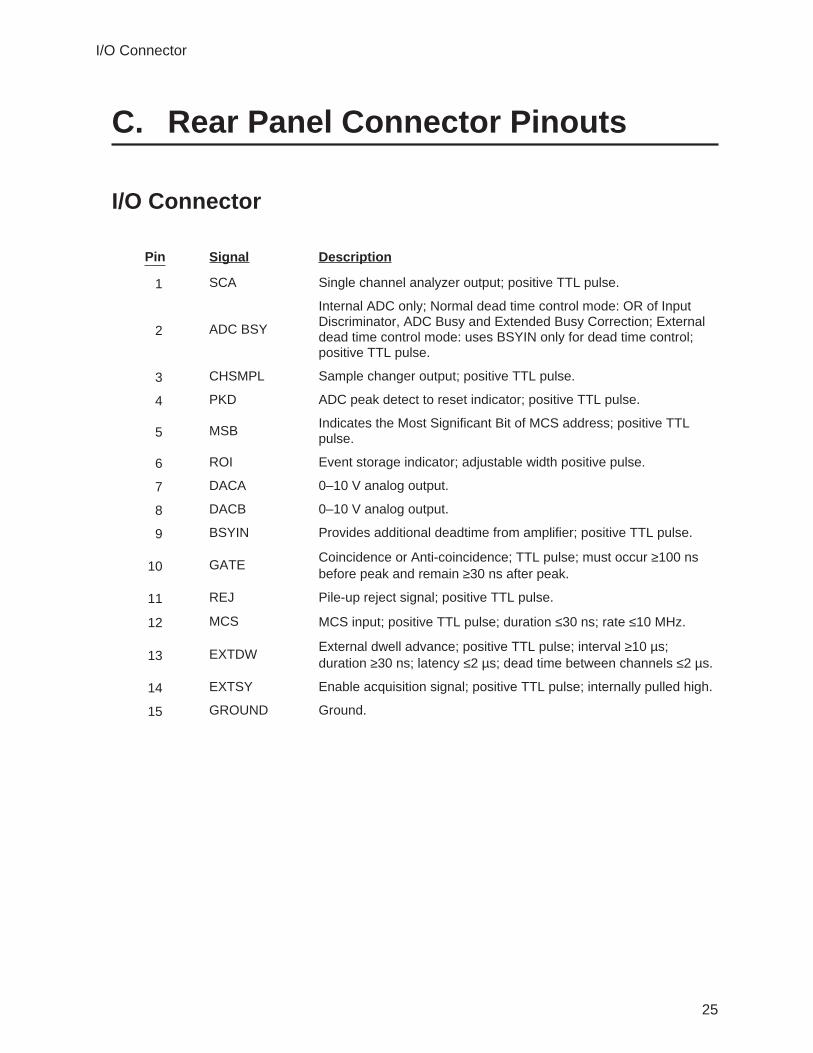
I/O Connector
Pin Signal Description
1 SCA Single channel analyzer output; positive TTL pulse.
2 ADC BSY
Internal ADC only; Normal dead time control mode: OR of InputDiscriminator, ADC Busy and Extended Busy Correction; Externaldead time control mode: uses BSYIN only for dead time control;positive TTL pulse.
3 CHSMPL Sample changer output; positive TTL pulse.
4 PKD ADC peak detect to reset indicator; positive TTL pulse.
5 MSBIndicates the Most Significant Bit of MCS address; positive TTLpulse.
6 ROI Event storage indicator; adjustable width positive pulse.
7 DACA 0–10 V analog output.
8 DACB 0–10 V analog output.
9 BSYIN Provides additional deadtime from amplifier; positive TTL pulse.
10 GATECoincidence or Anti-coincidence; TTL pulse; must occur ≥100 nsbefore peak and remain ≥30 ns after peak.
11 REJ Pile-up reject signal; positive TTL pulse.
12 MCS MCS input; positive TTL pulse; duration ≤30 ns; rate ≤10 MHz.
13 EXTDWExternal dwell advance; positive TTL pulse; interval ≥10 µs;duration ≥30 ns; latency ≤2 µs; dead time between channels ≤2 µs.
14 EXTSY Enable acquisition signal; positive TTL pulse; internally pulled high.
15 GROUND Ground.
25
I/O Connector
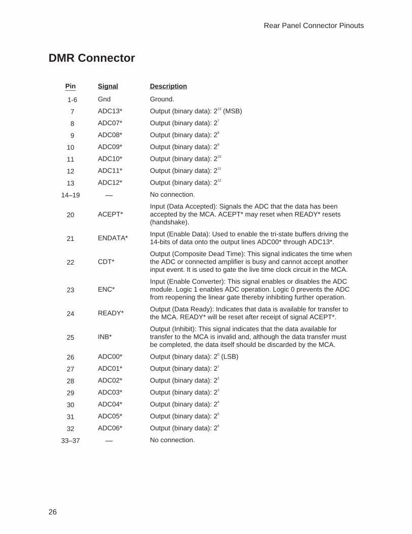
DMR Connector
Pin Signal Description
1-6 Gnd Ground.
7 ADC13* Output (binary data): 213 (MSB)
8 ADC07* Output (binary data): 27
9 ADC08* Output (binary data): 28
10 ADC09* Output (binary data): 29
11 ADC10* Output (binary data): 210
12 ADC11* Output (binary data): 211
13 ADC12* Output (binary data): 212
14–19 — No connection.
20 ACEPT*Input (Data Accepted): Signals the ADC that the data has beenaccepted by the MCA. ACEPT* may reset when READY* resets(handshake).
21 ENDATA*Input (Enable Data): Used to enable the tri-state buffers driving the14-bits of data onto the output lines ADC00* through ADC13*.
22 CDT*Output (Composite Dead Time): This signal indicates the time whenthe ADC or connected amplifier is busy and cannot accept anotherinput event. It is used to gate the live time clock circuit in the MCA.
23 ENC*Input (Enable Converter): This signal enables or disables the ADCmodule. Logic 1 enables ADC operation. Logic 0 prevents the ADCfrom reopening the linear gate thereby inhibiting further operation.
24 READY*Output (Data Ready): Indicates that data is available for transfer tothe MCA. READY* will be reset after receipt of signal ACEPT*.
25 INB*Output (Inhibit): This signal indicates that the data available fortransfer to the MCA is invalid and, although the data transfer mustbe completed, the data itself should be discarded by the MCA.
26 ADC00* Output (binary data): 20 (LSB)
27 ADC01* Output (binary data): 21
28 ADC02* Output (binary data): 22
29 ADC03* Output (binary data): 23
30 ADC04* Output (binary data): 24
31 ADC05* Output (binary data): 25
32 ADC06* Output (binary data): 26
33–37 — No connection.
26
Rear Panel Connector Pinouts
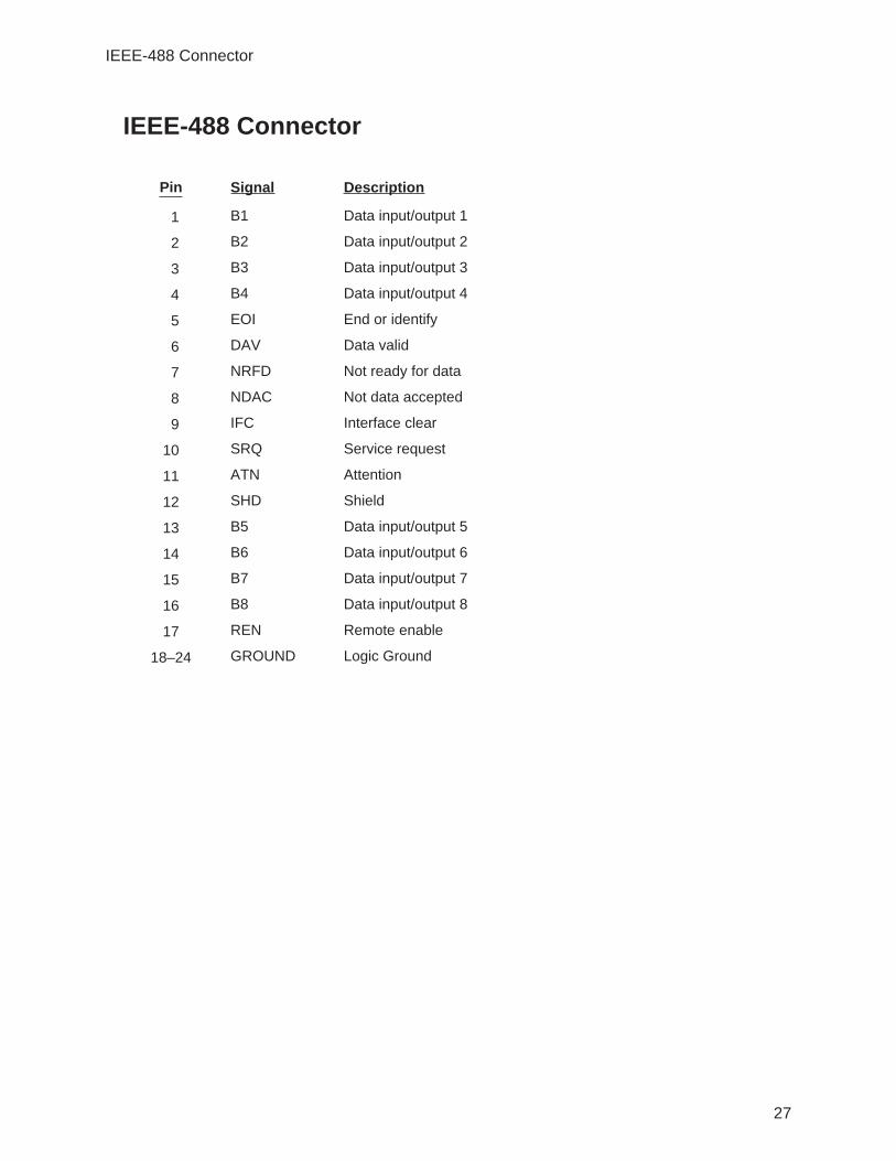
IEEE-488 Connector
Pin Signal Description
1 B1 Data input/output 1
2 B2 Data input/output 2
3 B3 Data input/output 3
4 B4 Data input/output 4
5 EOI End or identify
6 DAV Data valid
7 NRFD Not ready for data
8 NDAC Not data accepted
9 IFC Interface clear
10 SRQ Service request
11 ATN Attention
12 SHD Shield
13 B5 Data input/output 5
14 B6 Data input/output 6
15 B7 Data input/output 7
16 B8 Data input/output 8
17 REN Remote enable
18–24 GROUND Logic Ground
27
IEEE-488 Connector

Request for Schematics
Schematics for this unit are available directly from Canberra. Write, call or FAX:
Training and Technical Services DepartmentCanberra Industries800 Research Parkway, Meriden, CT 06450Telephone: (800) 255-6370 or (203) 639-2467FAX: (203) 235-1347
If you would like a set of schematics for this unit, please provide us with the followinginformation.
Your Name _______________________________________
Your Address _______________________________________
_______________________________________
_______________________________________
_______________________________________
_______________________________________
Unit’s model number _________________________
Unit’s serial number _________________________
Note: Schematics are provided for information only; if you service or repair ortry to service or repair this unit without Canberra’s written permission you mayvoid your warranty.