multisync lcd175vxm+ multisync lcd195vxm+ · english-2 for the customer to ... figure 1 figure 2...
TRANSCRIPT
MultiSync LCD175VXM+MultiSync LCD195VXM+User’s Manual
Eng
lish
English-1
Declaration
Declaration of the Manufacturer
TO PREVENT FIRE OR SHOCK HAZARDS, DO NOT EXPOSE THIS UNIT TO RAIN OR MOISTURE. ALSO, DO NOTUSE THIS UNIT’S POLARIZED PLUG WITH AN EXTENSION CORD RECEPTACLE OR OTHER OUTLETS UNLESSTHE PRONGS CAN BE FULLY INSERTED.
REFRAIN FROM OPENING THE CABINET AS THERE ARE HIGH VOLTAGE COMPONENTS INSIDE. REFERSERVICING TO QUALIFIED SERVICE PERSONNEL.
WARNING
CAUTION
CAUTION: TO REDUCE THE RISK OF ELECTRIC SHOCK, DO NOT REMOVE COVER (OR BACK). NO USERSERVICEABLE PARTS INSIDE. REFER SERVICING TO QUALIFIED SERVICE PERSONNEL.
This symbol warns user that uninsulated voltage within the unit may have sufficient magnitude to causeelectric shock. Therefore, it is dangerous to make any kind of contact with any part inside this unit.
This symbol alerts the user that important literature concerning the operation and maintenance of this unithas been included. Therefore, it should be read carefully in order to avoid any problems.
RISK OF ELECTRIC SHOCK • DO NOT OPEN
As an ENERGY STAR Partner, NEC Display Solutions of America, Inc. has determined that this product meets the ENERGY STAR
guidelines for energy efficiency. ENERGY STAR is a U.S. registered mark. The ENERGY STAR emblem does not represent EPAendorsement of any product or service.ErgoDesign is a registered trademark of NEC Display Solutions, Ltd. in Austria, Benelux, Denmark, France, Germany, Italy,Norway, Spain, Sweden, U.K..IBM PC/XT/AT, PS/2, MCGA, VGA, 8514/A and XGA are registered trademarks of International Business MachinesCorporation.Apple and Macintosh are registered trademarks of Apple Computer Inc.Microsoft and Windows are registered trademarks of the Microsoft Corporation.NEC is a registered trademark of NEC Corporation.All other trademarks or registered trademarks are property of their respective owners.
We hereby certify that the colour monitors MultiSyncLCD175VXM+ (L174F1)/LCD195VXM+ (L194F2)are in compliance with
Council Directive 73/23/EEC:– EN 60950-1
Council Directive 89/336/EEC:– EN 55022– EN 61000-3-2– EN 61000-3-3– EN 55024
and marked with
NEC Display Solutions, Ltd.4-13-23, Shibaura,
Minato-KuTokyo 108-0023, Japan
Caution:When operating the MultiSync LCD175VXM+/LCD195VXM+ with a 220-240V AC power source in Europe, use the power cordprovided with the monitor.
In the UK, a BS approved power cord with a moulded plug has a Black (five Amps) fuse installed for use with this equipment.If a power cord is not supplied with this equipment please contact your supplier.
For all other cases, use a power cord that matches the AC voltage of the power outlet and has been approved by andcomplies with the safety standard of your particular country.
English-2
For the Customer to use in U.S.A. or Canada
Canadian Department of Communications Compliance StatementDOC: This Class B digital apparatus meets all requirements of the Canadian Interference-Causing Equipment Regulations.
Cet appareil numérique de la classe B respecte toutes les exigences du Règlement sur le matériel brouiller du Canada.
C-UL: Bears the C-UL Mark and is in compliance with Canadian Safety Regulations according to CSA C22.2 No. 60950-1.
Ce produit porte la marque ‘C-UL’ et se conforme aux règlements de sûrele Canadiens selon CAN/CSA C22.2 No. 60950-1.
FCC Information1. Use the attached specified cables with the MultiSync LCD175VXM+/LCD195VXM+ colour monitor so as not to interfere
with radio and television reception.
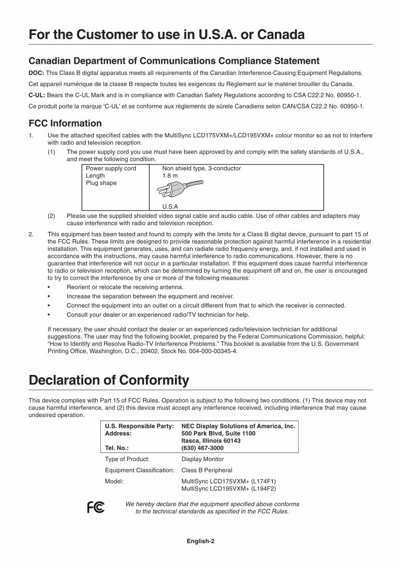
(1) The power supply cord you use must have been approved by and comply with the safety standards of U.S.A.,and meet the following condition.
Power supply cord Non shield type, 3-conductorLength 1.8 mPlug shape
U.S.A
(2) Please use the supplied shielded video signal cable and audio cable. Use of other cables and adapters maycause interference with radio and television reception.
2. This equipment has been tested and found to comply with the limits for a Class B digital device, pursuant to part 15 ofthe FCC Rules. These limits are designed to provide reasonable protection against harmful interference in a residentialinstallation. This equipment generates, uses, and can radiate radio frequency energy, and, if not installed and used inaccordance with the instructions, may cause harmful interference to radio communications. However, there is noguarantee that interference will not occur in a particular installation. If this equipment does cause harmful interferenceto radio or television reception, which can be determined by turning the equipment off and on, the user is encouragedto try to correct the interference by one or more of the following measures:
• Reorient or relocate the receiving antenna.
• Increase the separation between the equipment and receiver.
• Connect the equipment into an outlet on a circuit different from that to which the receiver is connected.
• Consult your dealer or an experienced radio/TV technician for help.
If necessary, the user should contact the dealer or an experienced radio/television technician for additionalsuggestions. The user may find the following booklet, prepared by the Federal Communications Commission, helpful:“How to Identify and Resolve Radio-TV Interference Problems.” This booklet is available from the U.S. GovernmentPrinting Office, Washington, D.C., 20402, Stock No. 004-000-00345-4.
Declaration of ConformityThis device complies with Part 15 of FCC Rules. Operation is subject to the following two conditions. (1) This device may notcause harmful interference, and (2) this device must accept any interference received, including interference that may causeundesired operation.
U.S. Responsible Party: NEC Display Solutions of America, Inc.Address: 500 Park Blvd, Suite 1100
Itasca, Illinois 60143Tel. No.: (630) 467-3000
Type of Product: Display Monitor
Equipment Classification: Class B Peripheral
Model: MultiSync LCD175VXM+ (L174F1)MultiSync LCD195VXM+ (L194F2)
We hereby declare that the equipment specified above conformsto the technical standards as specified in the FCC Rules.

Eng
lish
English-3
Figure 1 Figure 2
ContentsYour new NEC MultiSync LCD monitor box* should contain the following:
• MultiSync LCD monitor with tilt base
• Audio Cable
• Power Cord
• Video Signal Cable (15-pin mini D-SUB male to 15-pin mini D-SUB male)
• Video Signal Cable (DVI-D to DVI-D) (LCD195VXM+ only)
• User’s Manual
• CD-ROM
• Cable management cover
* Remember to save your original box and packing material to transport or ship the monitor.
Quick StartTo pull the stand, follow these instructions:
1. Place monitor face down on a non-abrasive surface (Figure 1).
2. Pull the stand holding the monitor with the other hand until the stand clicks (Figure 2).
NOTE: Handle with care when pulling the stand.
User’s Manual Audio Cable Power Cord 15-pin mini D-SUBmale to 15-pin mini
D-SUB male
DVI-D to DVI-D(LCD195VXM+ only) MultiSync LCD monitor
CD-ROMCable managementcover
Figure A.1 Figure A.3
MacintoshCable Adapter(not included)
Figure A.2
NOTE: Reverse this procedure if you need to re-pack the monitor.
To attach the MultiSync LCD monitor to your system, follow these instructions:
1. Turn off the power to your computer.
2. For the PC or MAC with DVI digital output: Connect the DVI-D signal cable to the connector of the display card in yoursystem (Figure A.1). Tighten all screws.
For the PC with Analog output: Connect the 15-pin mini D-SUB signal cable to the connector of the display card in yoursystem (Figure A.2). Tighten all screws.
For the Mac: Connect the MultiSync Macintosh cable adapter (not included) to the computer. Attach the 15-pin miniD-SUB signal cable to the MultiSync Macintosh cable adapter (Figure A.3). Tighten all screws.
NOTE: Some Macintosh systems do not require a Macintosh cable adapter.
English-4
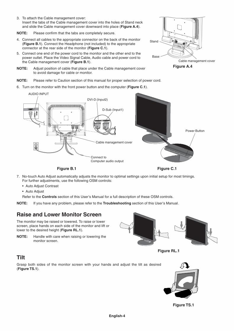
TiltGrasp both sides of the monitor screen with your hands and adjust the tilt as desired(Figure TS.1).
Figure B.1
Cable management cover
AUDIO INPUT
D-Sub (Input1)
Connect toComputer audio output
Figure C.1
Power Button
7. No-touch Auto Adjust automatically adjusts the monitor to optimal settings upon initial setup for most timings.For further adjustments, use the following OSM controls:
• Auto Adjust Contrast
• Auto Adjust
Refer to the Controls section of this User’s Manual for a full description of these OSM controls.
NOTE: If you have any problem, please refer to the Troubleshooting section of this User’s Manual.
DVI-D (Input2)
Figure RL.1
3. To attach the Cable management cover:Insert the tabs of the Cable management cover into the holes of Stand neckand slide the Cable management cover downward into place (Figure A.4).
NOTE: Please confirm that the tabs are completely secure.
4. Connect all cables to the appropriate connector on the back of the monitor(Figure B.1). Connect the Headphone (not included) to the appropriateconnector at the rear side of the monitor (Figure C.1).
5. Connect one end of the power cord to the monitor and the other end to thepower outlet. Place the Video Signal Cable, Audio cable and power cord tothe Cable management cover (Figure B.1).
NOTE: Adjust position of cable that place under the Cable management coverto avoid damage for cable or monitor.
Base
Stand
Cable management cover
Figure A.4
Figure TS.1
Raise and Lower Monitor ScreenThe monitor may be raised or lowered. To raise or lowerscreen, place hands on each side of the monitor and lift orlower to the desired height (Figure RL.1).
NOTE: Handle with care when raising or lowering themonitor screen.
NOTE: Please refer to Caution section of this manual for proper selection of power cord.
6. Turn on the monitor with the front power button and the computer (Figure C.1).
Eng
lish
English-5
Figure R.1
Non-abrasive surface
Figure R.2 Figure R.3
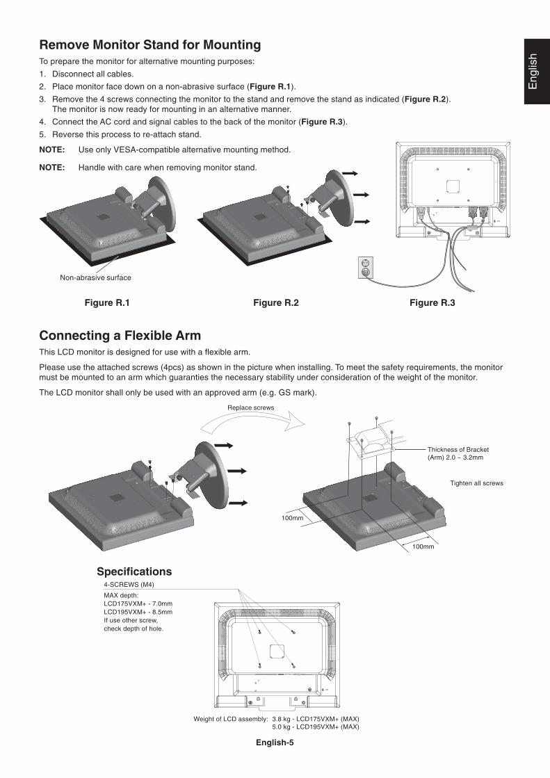
Connecting a Flexible ArmThis LCD monitor is designed for use with a flexible arm.
Please use the attached screws (4pcs) as shown in the picture when installing. To meet the safety requirements, the monitormust be mounted to an arm which guaranties the necessary stability under consideration of the weight of the monitor.
The LCD monitor shall only be used with an approved arm (e.g. GS mark).
Replace screws
Tighten all screws
100mm
100mm
Thickness of Bracket(Arm) 2.0 ~ 3.2mm
4-SCREWS (M4)
MAX depth:LCD175VXM+ - 7.0mmLCD195VXM+ - 8.5mmIf use other screw,check depth of hole.
Weight of LCD assembly: 3.8 kg - LCD175VXM+ (MAX)5.0 kg - LCD195VXM+ (MAX)
Specifications
Remove Monitor Stand for MountingTo prepare the monitor for alternative mounting purposes:
1. Disconnect all cables.
2. Place monitor face down on a non-abrasive surface (Figure R.1).
3. Remove the 4 screws connecting the monitor to the stand and remove the stand as indicated (Figure R.2).The monitor is now ready for mounting in an alternative manner.
4. Connect the AC cord and signal cables to the back of the monitor (Figure R.3).
5. Reverse this process to re-attach stand.
NOTE: Use only VESA-compatible alternative mounting method.
NOTE: Handle with care when removing monitor stand.

English-6
Controls
OSM (On-Screen Manager) control buttons on the front of the monitorfunction as follows:1. Basic function at pressing each key
2. OSM structure
Showing OSM. Shortcut to Bright adjustwindow.
Button
At No OSDshowing
Shortcut to Volume adjustwindow.
Input signal select.
At OSD showing(Icon selection stage)
Go to Adjustment stage. Cursor goes to left. Cursor goes to right.
At OSD showing(Adjustment stage)
Go to Icon selection stage. Adjust value decrease orCursor for adjust goes to left.
Adjust value increase orCursor for adjust goes toright.
Reset operation.Mute off/on switch on Volumeadjustment window.
SELECT – + 1<->2 / RESET
Main Menu (Icon Select, Analog Input)
Sub Menu (Icon Select)
Press“SELECT”
key
Press“SELECT”
key
Press “–” or “+”
Main Menu (Adjust)
Sub Menu (Adjust)
Press “SELECT” key
Press“SELECT” key
Adjust by using“–” or “+”
Adjust by using“–” or “+”
Press “–” or “+”
Example Tool:
Press “SELECT” key
Press“SELECT” key
Eng
lish
English-7
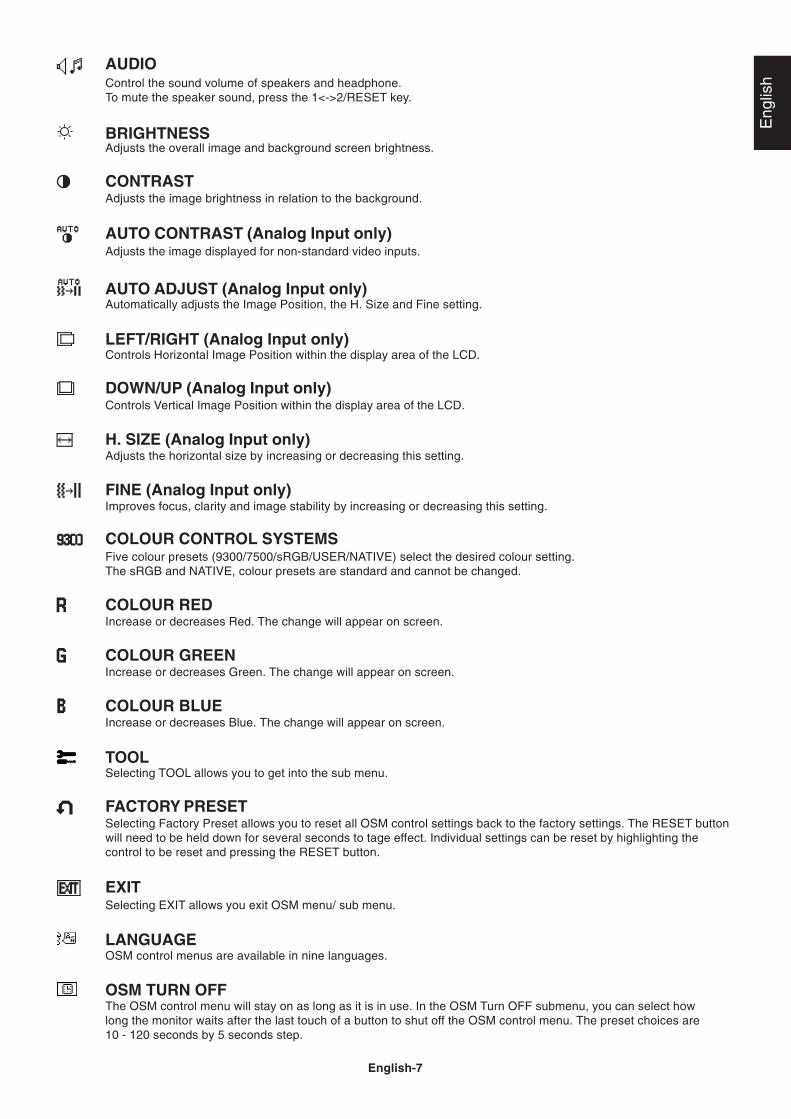
AUDIOControl the sound volume of speakers and headphone.To mute the speaker sound, press the 1<->2/RESET key.
BRIGHTNESSAdjusts the overall image and background screen brightness.
CONTRASTAdjusts the image brightness in relation to the background.
AUTO CONTRAST (Analog Input only)Adjusts the image displayed for non-standard video inputs.
AUTO ADJUST (Analog Input only)Automatically adjusts the Image Position, the H. Size and Fine setting.
LEFT/RIGHT (Analog Input only)Controls Horizontal Image Position within the display area of the LCD.
DOWN/UP (Analog Input only)Controls Vertical Image Position within the display area of the LCD.
H. SIZE (Analog Input only)Adjusts the horizontal size by increasing or decreasing this setting.
FINE (Analog Input only)Improves focus, clarity and image stability by increasing or decreasing this setting.
COLOUR CONTROL SYSTEMSFive colour presets (9300/7500/sRGB/USER/NATIVE) select the desired colour setting.The sRGB and NATIVE, colour presets are standard and cannot be changed.
COLOUR REDIncrease or decreases Red. The change will appear on screen.
COLOUR GREENIncrease or decreases Green. The change will appear on screen.
COLOUR BLUEIncrease or decreases Blue. The change will appear on screen.
TOOLSelecting TOOL allows you to get into the sub menu.
FACTORY PRESETSelecting Factory Preset allows you to reset all OSM control settings back to the factory settings. The RESET buttonwill need to be held down for several seconds to tage effect. Individual settings can be reset by highlighting thecontrol to be reset and pressing the RESET button.
EXITSelecting EXIT allows you exit OSM menu/ sub menu.
LANGUAGEOSM control menus are available in nine languages.
OSM TURN OFFThe OSM control menu will stay on as long as it is in use. In the OSM Turn OFF submenu, you can select howlong the monitor waits after the last touch of a button to shut off the OSM control menu. The preset choices are10 - 120 seconds by 5 seconds step.

English-8
OSM LOCK OUTThis control completely locks out access to all OSM control functions without Brightness and Contrast. Whenattempting to activate OSM controls while in the Lock Out mode, a screen will appear indicating the OSM arelocked out. To activate the OSM Lock Out function, press “1<->2/ RESET”, then “+” key and hold downsimultaneously. To de-activate the OSM Lock Out, press “1<->2/ RESET”, then “+” key and hold down simultaneously.
RESOLUTION NOTIFIERIf ON is selected, a message will appear on the screen after 30 seconds, notifying you that the resolution is not atoptimal resolution.
DDC/CITurns ON or OFF the two way communication and control of the monitor.
MONITOR INFOIndicates the model and serial numbers of your monitor.
OSM WarningOSM Warning menus disappear with SELECT button.
NO SIGNAL: This function gives a warning when there is no signal present. After power is turned on orwhen there is a change of input signal or video is inactive, the No Signal window will appear.
RESOLUTION NOTIFIER: This function gives a warning of use with optimized resolution. After power isturned on or when there is a change of input signal or the video signal doesn’t have proper resolution, theResolution Notifier window will open. This function can be disabled in the TOOL menu.
OUT OF RANGE: This function gives a recommendation of the optimized resolution and refresh rate. Afterthe power is turned on or there is a change of input signal or the video signal doesn’t have proper timing,the Out Of Range menu will appear.
Eng
lish
English-9
Recommended useSafety Precautions and Maintenance
FOR OPTIMUM PERFORMANCE, PLEASE NOTETHE FOLLOWING WHEN SETTING UP AND
USING THE MULTISYNC LCD COLOUR MONITOR:
• DO NOT OPEN THE MONITOR. There are no user serviceable parts inside and opening or removing covers may exposeyou to dangerous shock hazards or other risks. Refer all servicing to qualified service personnel.
• Do not spill any liquids into the cabinet or use your monitor near water.
• Do not insert objects of any kind into the cabinet slots, as they may touch dangerous voltage points, which can be harmfulor fatal or may cause electric shock, fire or equipment failure.
• Do not place any heavy objects on the power cord. Damage to the cord may cause shock or fire.
• Do not place this product on a sloping or unstable cart, stand or table, as the monitor may fall, causing serious damage tothe monitor.
• When operating the LCD monitor with its AC 125-240V power supply, use a power supply aord that matches the powersupply voltage of the AC power outlet being used. The power supply cord you use must have been approved by andcomply with the safety standards of your country. (Type H05VV-F should be used in Europe).
• In U.K, use a BS-approved power cord with molded plug having a black (5A) fuse installed for use with this monitor.If a power cord is not supplied with this monitor, please contact your supplier.
• Do not place any objects onto the monitor and do not use the monitor outdoors.
• The inside of the fluorescent tube located within the LCD monitor contains mercury. Please follow the bylaws or rules ofyour municipality to dispose of the tube properly.
• Do not bend power cord.
• Do not use monitor in high temperature, humid, dusty, or oily areas.
• Do not cover vent on monitor.
Immediately unplug your monitor from the wall outlet and refer servicing to qualified service personnel under the followingconditions:
• When the power supply cord or plug is damaged.
• If liquid has been spilled, or objects have fallen into the monitor.
• If the monitor has been exposed to rain or water.
• If the monitor has been dropped or the cabinet damaged.
• If the monitor does not operate normally by following operating instructions.
• If monitor is broken, do not come in contact with the liquid crystal and handle with care.
• Allow adequate ventilation around the monitor so that heat can properly dissipate. Do not block ventilatedopenings or place the monitor near a radiator or other heat sources. Do not put anything on top ofmonitor.
• The power cable connector is the primary means of detaching the system from the power supply. Themonitor should be installed close to a power outlet, which is easily accessible.
• Handle with care when transporting. Save packaging for transporting.
• Image Persistence: Please be aware that LCD Technology may experience a phenomenon known as Image Persistence.Image Persistence occurs when a residual or “ghost” image of a previous image remains visible on the screen. Unlike CRTmonitors, LCD monitors’ image persistence is not permanent, but constant images being displayed for a long period oftime should be avoided.To alleviate image persistence, turn off the monitor for as long as the previous image was displayed. For example, if animage was on the monitor for one hour and a residual image remains, the monitor should be turned off for one hour toerase the image.As with all personal display devices, NEC DISPLAY SOLUTIONS recommends displaying moving images and using amoving screen saver at regular intervals whenever the screen is idle or turning off the monitor when not in use.
CAUTION
English-10
CORRECT PLACEMENT AND ADJUSTMENT OF THE MONITOR CANREDUCE EYE, SHOULDER AND NECK FATIGUE. CHECK THE
FOLLOWING WHEN YOU POSITION THE MONITOR:
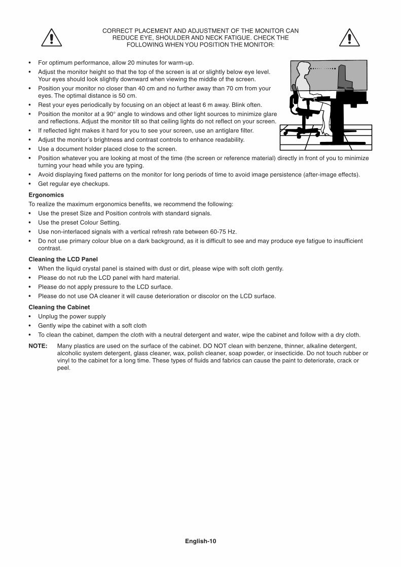
• For optimum performance, allow 20 minutes for warm-up.
• Adjust the monitor height so that the top of the screen is at or slightly below eye level.Your eyes should look slightly downward when viewing the middle of the screen.
• Position your monitor no closer than 40 cm and no further away than 70 cm from youreyes. The optimal distance is 50 cm.
• Rest your eyes periodically by focusing on an object at least 6 m away. Blink often.
• Position the monitor at a 90° angle to windows and other light sources to minimize glareand reflections. Adjust the monitor tilt so that ceiling lights do not reflect on your screen.
• If reflected light makes it hard for you to see your screen, use an antiglare filter.
• Adjust the monitor’s brightness and contrast controls to enhance readability.
• Use a document holder placed close to the screen.
• Position whatever you are looking at most of the time (the screen or reference material) directly in front of you to minimizeturning your head while you are typing.
• Avoid displaying fixed patterns on the monitor for long periods of time to avoid image persistence (after-image effects).
• Get regular eye checkups.
Ergonomics
To realize the maximum ergonomics benefits, we recommend the following:
• Use the preset Size and Position controls with standard signals.
• Use the preset Colour Setting.
• Use non-interlaced signals with a vertical refresh rate between 60-75 Hz.
• Do not use primary colour blue on a dark background, as it is difficult to see and may produce eye fatigue to insufficientcontrast.
Cleaning the LCD Panel
• When the liquid crystal panel is stained with dust or dirt, please wipe with soft cloth gently.
• Please do not rub the LCD panel with hard material.
• Please do not apply pressure to the LCD surface.
• Please do not use OA cleaner it will cause deterioration or discolor on the LCD surface.
Cleaning the Cabinet
• Unplug the power supply
• Gently wipe the cabinet with a soft cloth
• To clean the cabinet, dampen the cloth with a neutral detergent and water, wipe the cabinet and follow with a dry cloth.
NOTE: Many plastics are used on the surface of the cabinet. DO NOT clean with benzene, thinner, alkaline detergent,alcoholic system detergent, glass cleaner, wax, polish cleaner, soap powder, or insecticide. Do not touch rubber orvinyl to the cabinet for a long time. These types of fluids and fabrics can cause the paint to deteriorate, crack orpeel.

Eng
lish
English-11
Specifications for MultiSync LCD175VXM+Monitor Specifications MultiSync LCD175VXM+ Monitor Notes
LCD Module Diagonal: 43 cm/17 inches Active matrix; thin film transistor (TFT)Viewable Image Size: 43 cm/17 inches liquid crystal display (LCD); 0.264 mm dot
Native Resolution (Pixel Count): 1280 x 1024 pitch; 300 cd/m2 *2 white luminance, 700:1contrast ratio, typical; response time: 5 ms.
Input Signal Video: ANALOG 0.7 Vp-p/75 Ohms Digital Input: DVI-DSync: Separate sync.TTL Level (Positive/Negative)
Horizontal sync. Positive/NegativeVertical sync. Positive/Negative
Display Colours Analog input: 16,7 M Depends on display card used.
Synchronization Range Horizontal: 31.5 kHz to 81.1 kHz AutomaticallyVertical: 56 Hz to 76 Hz Automatically
Viewing Angle Left/Right: -80°/+80° (CR>10), -88°/+88° (CR>5)Up/Down: -75°/+85° (CR>10), -85°/+85° (CR>5)
Resolutions Supported Landscape: 720 x 400*1 : VGA Some systems may not640 x 480*1 @ 60 Hz to 75 Hz support all modes listed.800 x 600*1 @ 56 Hz to 75 Hz832 x 624*1 @ 75 Hz1024 x 768*1 @ 60 Hz to 75 Hz1152 x 864*1 @ 70 Hz to 75 Hz1152 x 870*1 @ 75 Hz1280 x 960*1 @ 60 Hz to 75 Hz Recommended resolution is 60 Hz for1280 x 1024 @ 60 Hz to 75 Hz................... optimal display performance.
Active Display Area Horizontal: 337.9 mmVertical: 270.3 mm
Speakers Practical Audio Output: 1.0 W + 1.0 W
Power Supply 100 - 240 V ~ 50/60 Hz
Power Consumption 34 W
Dimensions Landscape: 368.0 mm (W) x 358.5 - 408.5 mm (H) x 230.0 mm (D) (with stand)368.0 mm (W) x 320.5 mm (H) x 61.0 mm (D) (without stand)
Weight with stand: 4.8 kgwithout stand: 3.8 kg
Environmental ConsiderationsOperating Temperature: 5 °C to 35 °C
Humidity: 30% to 80%Altitude: 0 to 3,048 m
Storage Temperature: -10 °C to +60 °CHumidity: 10% to 85%Altitude: 0 to 12,192 m
*1 Interpolated Resolutions: When resolutions are shown that are lower than the pixel count of the LCD module, text may appear different. This isnormal and necessary for all current flat panel technologies when displaying non-native resolutions full screen. In flat panel technologies, each dot onthe screen is actually one pixel, so to expand resolutions to full screen, an interpolation of the resolution must be done.*2 LCD Module at 25°C.
NOTE: Technical specifications are subject to change without notice.
English-12
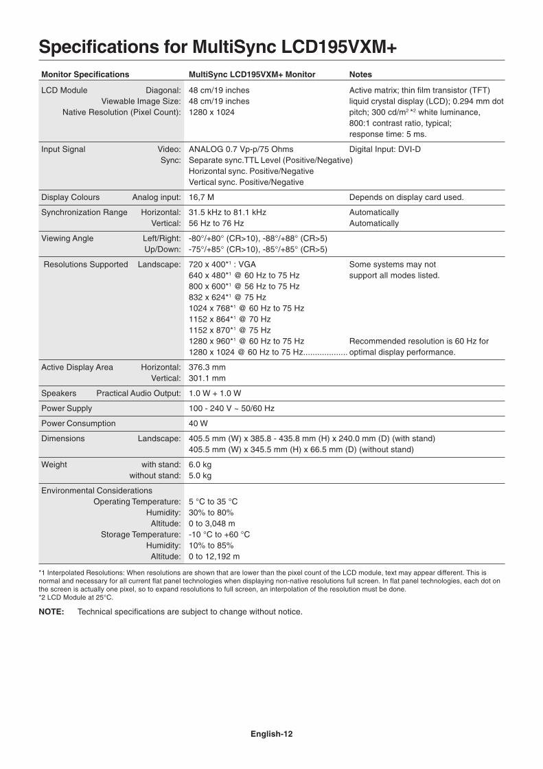
Specifications for MultiSync LCD195VXM+Monitor Specifications MultiSync LCD195VXM+ Monitor Notes
LCD Module Diagonal: 48 cm/19 inches Active matrix; thin film transistor (TFT)Viewable Image Size: 48 cm/19 inches liquid crystal display (LCD); 0.294 mm dot
Native Resolution (Pixel Count): 1280 x 1024 pitch; 300 cd/m2 *2 white luminance,800:1 contrast ratio, typical;response time: 5 ms.
Input Signal Video: ANALOG 0.7 Vp-p/75 Ohms Digital Input: DVI-DSync: Separate sync.TTL Level (Positive/Negative)
Horizontal sync. Positive/NegativeVertical sync. Positive/Negative
Display Colours Analog input: 16,7 M Depends on display card used.
Synchronization Range Horizontal: 31.5 kHz to 81.1 kHz AutomaticallyVertical: 56 Hz to 76 Hz Automatically
Viewing Angle Left/Right: -80°/+80° (CR>10), -88°/+88° (CR>5)Up/Down: -75°/+85° (CR>10), -85°/+85° (CR>5)
Resolutions Supported Landscape: 720 x 400*1 : VGA Some systems may not640 x 480*1 @ 60 Hz to 75 Hz support all modes listed.800 x 600*1 @ 56 Hz to 75 Hz832 x 624*1 @ 75 Hz1024 x 768*1 @ 60 Hz to 75 Hz1152 x 864*1 @ 70 Hz1152 x 870*1 @ 75 Hz1280 x 960*1 @ 60 Hz to 75 Hz Recommended resolution is 60 Hz for1280 x 1024 @ 60 Hz to 75 Hz................... optimal display performance.
Active Display Area Horizontal: 376.3 mmVertical: 301.1 mm
Speakers Practical Audio Output: 1.0 W + 1.0 W
Power Supply 100 - 240 V ~ 50/60 Hz
Power Consumption 40 W
Dimensions Landscape: 405.5 mm (W) x 385.8 - 435.8 mm (H) x 240.0 mm (D) (with stand)405.5 mm (W) x 345.5 mm (H) x 66.5 mm (D) (without stand)
Weight with stand: 6.0 kgwithout stand: 5.0 kg
Environmental ConsiderationsOperating Temperature: 5 °C to 35 °C
Humidity: 30% to 80%Altitude: 0 to 3,048 m
Storage Temperature: -10 °C to +60 °CHumidity: 10% to 85%Altitude: 0 to 12,192 m
*1 Interpolated Resolutions: When resolutions are shown that are lower than the pixel count of the LCD module, text may appear different. This isnormal and necessary for all current flat panel technologies when displaying non-native resolutions full screen. In flat panel technologies, each dot onthe screen is actually one pixel, so to expand resolutions to full screen, an interpolation of the resolution must be done.*2 LCD Module at 25°C.
NOTE: Technical specifications are subject to change without notice.
Eng
lish
English-13
FeaturesReduced Footprint: Provides the ideal solution for environments requiring superior image quality but with size and weightlimitations. The small footprint and low weight allow it to be moved or transported easily from one location to another.
Colour Control System: Allows you to adjust the colours on your screen and customize the colour accuracy of your monitorto a variety of standards.
OSM (On-Screen Manager) Controls: Allow you to quickly and easily adjust all elements of your screen image via simple touse on-screen menus.
No-touch Auto Adjust: No-touch Auto Adjust automatically adjusts the monitor to optimal settings upon initial setup.
ErgoDesign Features: Enhance human ergonomics to improve the working environment, protect the health of the user andsave money. Examples include OSM controls for quick and easy image adjustments, tilt base for preferred angle of vision,small footprint and compliance with MPRII and TCO guidelines for lower emissions.
Plug and Play: The Microsoft solution with the Windows operating system facilitates setup and installation by allowing themonitor to send its capabilities (such as screen size and resolutions supported) directly to your computer, automaticallyoptimizing display performance.
IPM (Intelligent Power Manager) System: Provides innovative power-saving methods that allow the monitor to shift to alower power consumption level when on but not in use, saving two-thirds of your monitor energy costs, reducing emissionsand lowering the air conditioning costs of the workplace.
Multiple Frequency Technology: Automatically adjusts monitor to the display card’s scanning frequency, thus displaying theresolution required.
FullScan Capability: Allows you to use the entire screen area in most resolutions, significantly expanding image size.
VESA Standard Mounting Interface: Allows users to connect their MultiSync monitor to any VESA standard third partymounting arm or bracket. Allows for the monitor to be mounted on a wall or an arm using any third party compliant device.

English-14
TroubleshootingNo picture
• The signal cable should be completely connected to the display card/computer.
• The display card should be completely seated in its slot.
• Check front power Switch and computer power switch should be in the ON position.
• Check to make sure that a supported mode has been selected on the display card or system being used. (Pleaseconsult display card or system manual to change graphics mode.)
• Check the monitor and your display card with respect to compatibility and recommended settings.
• Check the signal cable connector for bent or pushed-in pins.
• Check the signal input.
Power Button does not respond• Unplug the power cord of the monitor from the AC outlet to turn off and reset the monitor.
Image persistence• Please be aware that LCD Technology may experience a phenomenon known as Image Persistence. Image
Persistence occurs when a residual or “ghost” image of a previous image remains visible on the screen. Unlike CRTmonitors, LCD monitors’ image persistence is not permanent, but constant images being displayed for a long period oftime should be avoided.To alleviate image persistence, turn off the monitor for as long as the previous image was displayed. For example, if animage was on the monitor for one hour and a residual image remains, the monitor should be turned off for one hour toerase the image.As with all personal display devices, NEC DISPLAY SOLUTIONS recommends displaying moving images and using amoving screen saver at regular intervals whenever the screen is idle or turning off the monitor when not in use.
Image is unstable, unfocused or swimming is apparent• Signal cable should be completely attached to the computer.
• Use the OSM Image Adjust controls to focus and adjust display by increasing or decreasing the fine total. When thedisplay mode is changed, the OSM Image Adjust settings may need to be re-adjusted.
• Check the monitor and your display card with respect to compatibility and recommended signal timings.
• If your text is garbled, change the video mode to non-interlace and use 60 Hz refresh rate.
LED on monitor is not lit (no green or amber colour can be seen)• Power Switch should be in the ON position and power cord should be connected.
Display image is not sized properly• Use the OSM Image Adjust controls to increase or decrease the H.SIZE.
• Check to make sure that a supported mode has been selected on the display card or system being used.(Please consult display card or system manual to change graphics mode.)
No Video• If no video is present on the screen, turn the Power button off and on again.
• Make certain the computer is not in a power-saving mode (touch the keyboard or mouse).
No Sound• Check to see if speaker cable is properly connected.
• Check to see if mute is activated.
• Check to see if volume in OSM is set at minimum.
Eng
lish
English-15
TCO’03
Congratulations!The display you have just purchased carries the TCO’03 Displayslabel. This means that your display is designed, manufactured andtested according to some of the strictest quality and environmentalrequirements in the world. This makes for a high performanceproduct, designed with the user in focus that also minimizes theimpact on our natural environment.
Some of the features of the TCO’03 Display requirements:
Ergonomics• Good visual ergonomics and image quality in order to improve the working environment for
the user and to reduce sight and strain problems. Important parameters are luminance,contrast, resolution, reflectance, colour rendition and image stability.
Energy• Energy-saving mode after a certain time – beneficial both for the user and the environment• Electrical safety
Emissions• Electromagnetic fields• Noise emissions
Ecology• The product must be prepared for recycling and the manufacturer must have a certified
environmental management system such as EMAS or ISO 14 001• Restrictions on:
- chlorinated and brominated flame retardants and polymers- heavy metals such as cadmium, mercury and lead.
The requirements included in this label have been developed by TCO Development in co-operation with scientists, experts, users as well as manufacturers all over the world. Since theend of the 1980s TCO has been involved in influencing the development of IT equipment in amore user-friendly direction. Our labelling system started with displays in 1992 and is nowrequested by users and IT-manufacturers all over the world.
For more information, please visitwww.tcodevelopment.com
English-16
NEC DISPLAY SOLUTIONS is strongly committed to environmental protection and sees recycling as one of the company’stop priorities in trying to minimize the burden placed on the environment. We are engaged in developing environmentally-friendly products, and always strive to help define and comply with the latest independent standards from agencies such asISO (International Organisation for Standardization) and TCO (Swedish Trades Union).
Disposing of your old NEC productThe aim of recycling is to gain an environmental benefit by means of re-use, upgrading, reconditioning or reclamation ofmaterial. Dedicated recycling sites ensure that environmentally harmful components are properly handled and securelydisposed. To ensure the best recycling of our products, NEC DISPLAY SOLUTIONS offers a variety of recyclingprocedures and gives advice on how to handle the product in an environmentally sensitive way, once it has reached the endof its life.
All required information concerning the disposal of the product and country-specific information on recycling facilities can befound on our following websites:
http://www.nec-display-solutions.com/greencompany/ (in Europe),
http://www.nec-display.com (in Japan) or
http://www.necdisplay.com (in USA).
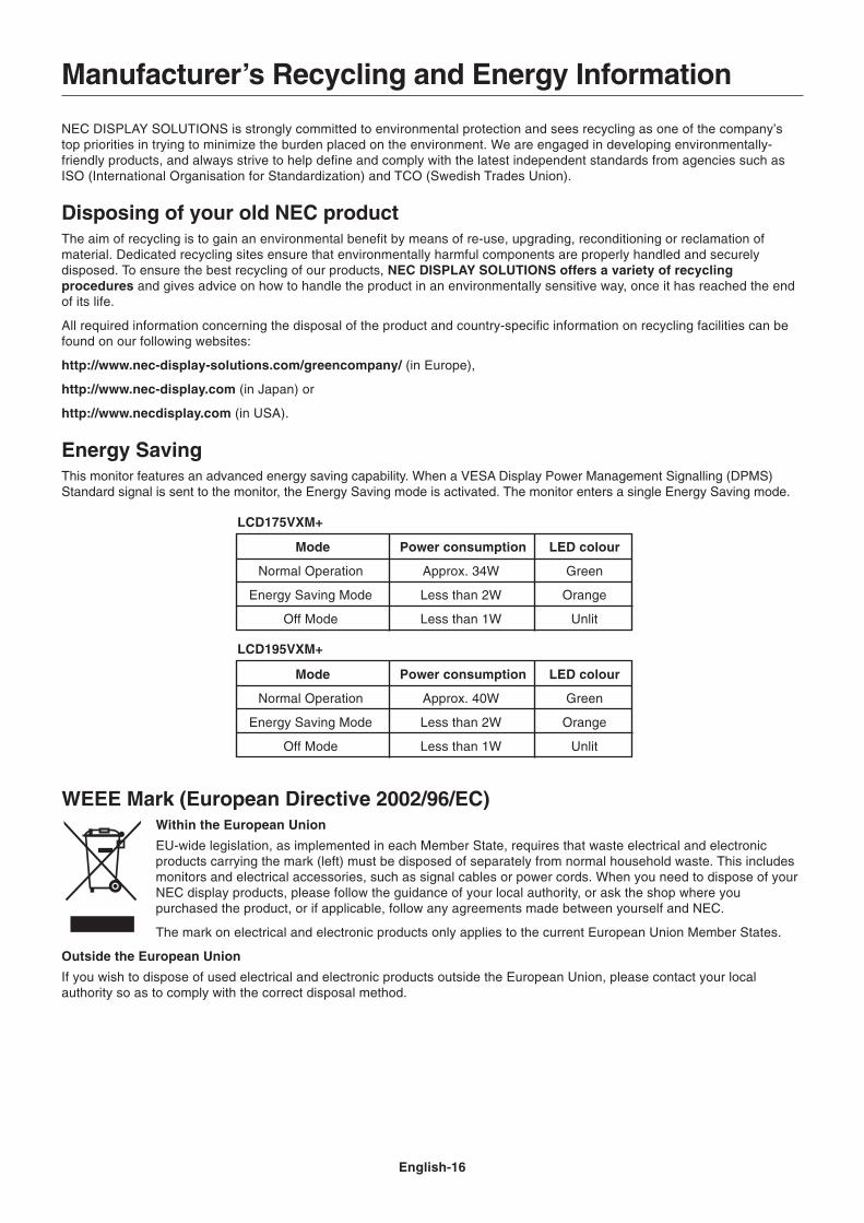
Energy SavingThis monitor features an advanced energy saving capability. When a VESA Display Power Management Signalling (DPMS)Standard signal is sent to the monitor, the Energy Saving mode is activated. The monitor enters a single Energy Saving mode.
Mode Power consumption LED colour
Normal Operation Approx. 34W Green
Energy Saving Mode Less than 2W Orange
Off Mode Less than 1W Unlit
Mode Power consumption LED colour
Normal Operation Approx. 40W Green
Energy Saving Mode Less than 2W Orange
Off Mode Less than 1W Unlit
Manufacturer’s Recycling and Energy Information
WEEE Mark (European Directive 2002/96/EC)Within the European Union
EU-wide legislation, as implemented in each Member State, requires that waste electrical and electronicproducts carrying the mark (left) must be disposed of separately from normal household waste. This includesmonitors and electrical accessories, such as signal cables or power cords. When you need to dispose of yourNEC display products, please follow the guidance of your local authority, or ask the shop where youpurchased the product, or if applicable, follow any agreements made between yourself and NEC.
The mark on electrical and electronic products only applies to the current European Union Member States.
Outside the European Union
If you wish to dispose of used electrical and electronic products outside the European Union, please contact your localauthority so as to comply with the correct disposal method.
LCD195VXM+
LCD175VXM+