multisync p401 multisync p461 multisync...
TRANSCRIPT
User’s Manual
MultiSync P401MultiSync P461MultiSync P521
Index
Declaration of conformity ............................................................................................................................. English-1Important Information ................................................................................................................................... English-2
WARNING, CAUTION ........................................................................................................................ English-2Declaration ................................................................................................................................................... English-2Safety Precautions, Maintenance & Recommended Use ............................................................................ English-3Contents ....................................................................................................................................................... English-4Installation .................................................................................................................................................... English-5Parts Name and Functions .......................................................................................................................... English-7
Control Panel ...................................................................................................................................... English-7Terminal Panel .................................................................................................................................... English-8Wireless Remote Control ................................................................................................................... English-10Operating Range for the Remote Control ........................................................................................... English-11
Handling the remote control ........................................................................................................... English-11Setup ............................................................................................................................................................ English-12Connections ................................................................................................................................................. English-14
Wiring Diagram................................................................................................................................... English-14Connecting a Personal Computer ...................................................................................................... English-15Connecting a DVD Player with HDMI out ........................................................................................... English-15Connecting a Computer with DisplayPort ........................................................................................... English-15
Basic Operation ........................................................................................................................................... English-16Power ON and OFF Modes ................................................................................................................ English-16Power Indicator .................................................................................................................................. English-17Using Power Management ................................................................................................................. English-17Selecting a video source .................................................................................................................... English-17Picture Aspect .................................................................................................................................... English-17Information OSD................................................................................................................................. English-18Picture Mode ...................................................................................................................................... English-18
OSD (On-Screen-Display) Controls ............................................................................................................. English-19PICTURE............................................................................................................................................ English-20ADJUST ............................................................................................................................................. English-20AUDIO ................................................................................................................................................ English-21SCHEDULE ........................................................................................................................................ English-21PIP ...................................................................................................................................................... English-22OSD .................................................................................................................................................... English-22MULTI DISPLAY ................................................................................................................................. English-23DISPLAY PROTECTION .................................................................................................................... English-24ADVANCED OPTION ......................................................................................................................... English-24
Remote Control Function ............................................................................................................................. English-27Controlling the LCD monitor via RS-232C Remote Control ......................................................................... English-29Controlling the LCD monitor via LAN Control .............................................................................................. English-30Features ....................................................................................................................................................... English-33Troubleshooting ........................................................................................................................................... English-34Specifications - P401 ................................................................................................................................... English-35Specifications - P461 ................................................................................................................................... English-36Specifications - P521 ................................................................................................................................... English-37Pin Assignment ............................................................................................................................................ English-38Manufacturer’s Recycling and Energy Information ...................................................................................... English-39
www.necdisplaysolutions.com
English-1
Eng
lishDECLARATION OF CONFORMITY
This device complies with Part 15 of FCC Rules. Operation is subject to the following two conditions. (1) This device may notcause harmful interference, and (2) this device must accept any interference received, including interference that may causeundesired operation.
U.S. Responsible Party: NEC Display Solutions of America, Inc.Address: 500 Park Boulevard, Suite 1100
Itasca, Illinois 60143Tel. No.: (630) 467-3000
Type of Product: Display Monitor
Equipment Classification: Class B Peripheral
Model: MultiSync P401 (L408TM)MultiSync P461 (L468TN)MultiSync P521 (L528N7)
We hereby declare that the equipment specified aboveconforms to the technical standards as specified in the FCC Rules.
Canadian Department of Communications Compliance Statement
DOC: This Class B digital apparatus meets all requirements of the Canadian Interference-Causing Equipment Regulations.
C-UL: Bears the C-UL Mark and is in compliance with Canadian Safety Regulations according to CAN/CSA C22.2 No. 60950-1.
FCC Information1. Use the attached specified cables with the MultiSync P401 (L408TM)/MultiSync P461 (L468TN)/MultiSync P521 (L528N7)
colour monitor so as not to interfere with radio and television reception.(1) Please use the supplied power cord or equivalent to ensure FCC compliance.(2) Please use the supplied shielded video signal cable, Mini D-SUB 15 pin to Mini D-SUB 15 pin.
2. This equipment has been tested and found to comply with the limits for a Class B digital device, pursuant to part 15 of theFCC Rules. These limits are designed to provide reasonable protection against harmful interference in a residential installa-tion. This equipment generates, uses, and can radiate radio frequency energy, and, if not installed and used in accordancewith the instructions, may cause harmful interference to radio communications. However, there is no guarantee that interfer-ence will not occur in a particular installation. If this equipment does cause harmful interference to radio or television reception,which can be determined by turning the equipment off and on, the user is encouraged to try to correct the interference byone or more of the following measures:• Reorient or relocate the receiving antenna.• Increase the separation between the equipment and receiver.• Connect the equipment into an outlet on a circuit different from that to which the receiver is connected.• Consult your dealer or an experienced radio/TV technician for help.
If necessary, the user should contact the dealer or an experienced radio/television technician for additional suggestions.The user may find the following booklet, prepared by the Federal Communications Commission, helpful: “How to Identifyand Resolve Radio-TV Interference Problems.” This booklet is available from the U.S. Government Printing Office, Washington,D.C., 20402, Stock No. 004-000-00345-4.
Windows is a registered trademark of Microsoft Corporation.NEC is a registered trademark of NEC Corporation.OmniColor is a registered trademark of NEC Display Solutions Europe GmbH in the countries of EU andSwitzerland.DisplayPort is trademarks of Video Electronics Standards Association.All other brands and product names are trademarks or registered trademarks of their respective owners.
HDMI, the HDMI logo and High-Definition Multimedia Interface are trademarks or registered trademarks of HDMI Licensing LLC.
English-2
Important Information
TO PREVENT FIRE OR SHOCK HAZARDS, DO NOT EXPOSE THIS UNIT TO RAIN OR MOISTURE. ALSO, DO NOTUSE THIS UNIT’S POLARIZED PLUG WITH AN EXTENSION CORD RECEPTACLE OR OTHER OUTLETS UNLESSTHE PRONGS CAN BE FULLY INSERTED.
REFRAIN FROM OPENING THE CABINET AS THERE ARE HIGH VOLTAGE COMPONENTS INSIDE.REFER SERVICING TO QUALIFIED SERVICE PERSONNEL.
WARNING
CAUTIONCAUTION: TO REDUCE THE RISK OF ELECTRIC SHOCK, MAKE SURE POWER CORD IS UNPLUGGED FROM
WALL SOCKET. TO FULLY DISENGAGE THE POWER TO THE UNIT, PLEASE DISCONNECT THEPOWER CORD FROM THE AC OUTLET. DO NOT REMOVE COVER (OR BACK). NO USERSERVICEABLE PARTS INSIDE. REFER SERVICING TO QUALIFIED SERVICE PERSONNEL.
This symbol warns user that uninsulated voltage within the unit may have sufficient magnitude to causeelectric shock. Therefore, it is dangerous to make any kind of contact with any part inside this unit.
This symbol alerts the user that important literature concerning the operation and maintenance of this unithas been included. Therefore, it should be read carefully in order to avoid any problems.
Declaration
Declaration of the Manufacturer
We hereby certify that the color monitor MultiSyncP401 (L408TM)/MultiSync P461 (L468TN)/MultiSyncP521 (L528N7) are in compliance with
Council Directive 2006/95/EC:– EN 60950-1
Council Directive 2004/108/EC:– EN 55022– EN 61000-3-2– EN 61000-3-3– EN 55024
and marked with
NEC Display Solutions, Ltd.4-13-23, Shibaura,
Minato-KuTokyo 108-0023, Japan
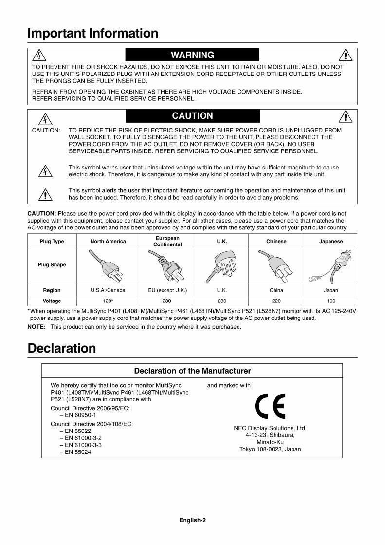
CAUTION: Please use the power cord provided with this display in accordance with the table below. If a power cord is notsupplied with this equipment, please contact your supplier. For all other cases, please use a power cord that matches theAC voltage of the power outlet and has been approved by and complies with the safety standard of your particular country.
*When operating the MultiSync P401 (L408TM)/MultiSync P461 (L468TN)/MultiSync P521 (L528N7) monitor with its AC 125-240Vpower supply, use a power supply cord that matches the power supply voltage of the AC power outlet being used.
NOTE: This product can only be serviced in the country where it was purchased.
Plug Type North AmericaEuropean
ContinentalU.K. Chinese Japanese
Plug Shape
Region
Voltage
U.S.A./Canada U.K. China JapanEU (except U.K.)
120* 230 220 100230

English-3
Eng
lish
FOR OPTIMUM PERFORMANCE, PLEASE NOTE THEFOLLOWING WHEN SETTING UP AND USING
THE MULTI-FUNCTION MONITOR:
• DO NOT OPEN THE MONITOR. There are no userserviceable parts inside and opening or removing coversmay expose you to dangerous shock hazards or other risks.Refer all servicing to qualified service personnel.
• Do not spill any liquids into the cabinet or use your monitornear water.
• Do not insert objects of any kind into the cabinet slots, asthey may touch dangerous voltage points, which can beharmful or fatal or may cause electric shock, fire orequipment failure.
• Do not place any heavy objects on the power cord.Damage to the cord may cause shock or fire.
• Do not place this product on a sloping or unstable cart,stand or table, as the monitor may fall, causing seriousdamage to the monitor.
• Do not mount this product face up, face down or upsidedown for an extended period of time as it may causepermanent damage to the screen.
• The power supply cord you use must have been approvedby and comply with the safety standards of your country.(Type H05VV-F 3G 1mm2 should be used in Europe)
• In UK, use a BS-approved power cord with molded plughaving a black (13A) fuse installed for use with this monitor.
• Do not place any objects onto the monitor and do not usethe monitor outdoors.
• The lamps in this product contain mercury. Pleasedispose according to state, local or federal law.
• Do not bend, crimp or otherwise damage the power cord.
• If glass is broken, handle with care.
• Do not cover vent on monitor.
• Do not use monitor in high temperature, humid, dusty, oroily areas.
• If monitor or glass is broken, do not come in contact with theliquid crystal and handle with care.
• Allow adequate ventilation around the monitor, so that heatcan properly dissipate. Do not block ventilated openings orplace the monitor near a radiator or other heat sources.Do not put anything on top of the monitor.
• The power cable connector is the primary means of detachingthe system from the power supply. The monitor should beinstalled close to a power outlet, which is easily accessible.
• Do not move or mount this product by hanging a rope or wireto the backside handle.Do not mount or secure this product by using the backsidehandle. It may fall and cause personal injury.
• Handle with care when transporting. Save packaging fortransporting.
• If using the cooling fan continuously, it is recommended towipe holes clean a minimum of once a month.
• Please clean the holes of back cabinet to reject dirt anddust at least once a year because of set reliability.
• When using a LAN cable, do not connect to a peripheraldevice with wiring that might have excessive voltage.
Connecting to a TV*
• Cable distribution system should be grounded (earthed) inaccordance with ANSI/NFPA 70, the National ElectricalCode (NEC), in particular Section 820.93, Grounding ofOuter Conductive Shield of a Coaxial Cable.
• The screen of the coaxial cable is intended to be connectedto earth in the building installation.
Immediately unplug your monitor from the wall outlet and referservicing to qualified service personnel under the followingconditions:
• When the power supply cord or plug is damaged.
• If liquid has been spilled, or objects have fallen into the monitor.
• If the monitor has been exposed to rain or water.
• If the monitor has been dropped or the cabinet damaged.
• If you notice any structural damage such as cracks orunnatural wobbling.
• If the monitor does not operate normally by followingoperating instructions.
Recommended Use• For optimum performance, allow 20 minutes for warm-up.
• Rest your eyes periodically by focusing on an object at least5 feet away. Blink often.
• Position the monitor at a 90° angle to windows and otherlight sources to minimize glare and reflections.
• Clean the LCD monitor surface with a lint-free, non-abrasivecloth. Avoid using any cleaning solution or glass cleaner!
• Adjust the monitor’s brightness, contrast and sharpnesscontrols to enhance readability.
• Avoid displaying fixed patterns on the monitor for longperiods of time to avoid image persistence (after imageeffects).
• Get regular eye checkups.
Ergonomics
To realize the maximum ergonomic benefits, we recommendthe following:
• Use the preset Size and Position controls with standardsignals.
• Use the preset Color Setting.
• Use non-interlaced signals.
• Do not use primary color blue on a dark background, as it isdifficult to see and may produce eye fatigue due toinsufficient contrast.
Cleaning the LCD Panel• When the liquid crystal panel is stained with dust or dirt,
please wipe with soft cloth gently.
• Please do not rub the LCD panel with hard material.
• Please do not apply pressure to the LCD surface.
• Please do not use OA cleaner it will cause deterioration ordiscolor on the LCD surface.
Cleaning the Cabinet• Unplug the power supply
• Gently wipe the cabinet with a soft cloth
• To clean the cabinet, dampen the cloth with a neutraldetergent and water, wipe the cabinet and follow with a drycloth.
NOTE: DO NOT clean with benzene thinner, alkaline detergent,alcoholic system detergent, glass cleaner, wax, polishcleaner, soap powder, or insecticide. Rubber or vinylshould not be in contact with the cabinet for anextended period of time. These types of fluids andmaterials can cause the paint to deteriorate, crack orpeel.
Safety Precautions, Maintenance & Recommended Use
* The product you purchased may not have this feature.
English-4
Contents
Power Cord*1
Setup Manual
Clamp x 3
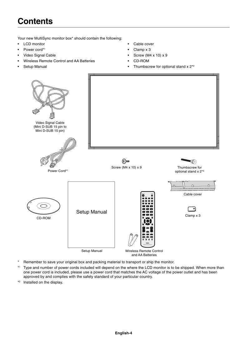
Your new MultiSync monitor box* should contain the following:
• LCD monitor
• Power cord*1
• Video Signal Cable
• Wireless Remote Control and AA Batteries
• Setup Manual
• Cable cover
• Clamp x 3
• Screw (M4 x 10) x 9
• CD-ROM
• Thumbscrew for optional stand x 2*2
CD-ROM
Screw (M4 x 10) x 9
* Remember to save your original box and packing material to transport or ship the monitor.
*1 Type and number of power cords included will depend on the where the LCD monitor is to be shipped. When more thanone power cord is included, please use a power cord that matches the AC voltage of the power outlet and has beenapproved by and complies with the safety standard of your particular country.
*2 Installed on the display.
Thumbscrew foroptional stand x 2*2
Setup Manual
Cable cover
Video Signal Cable(Mini D-SUB 15 pin to
Mini D-SUB 15 pin)
Wireless Remote Controland AA Batteries
English-5
Eng
lish
This device cannot be used or installed without the TabletopStand or other mounting accessory for support. For properinstallation it is strongly recommended to use a trained,NEC authorized service person. Failure to follow NECstandard mounting procedures could result in damage to theequipment or injury to the user or installer. Product warrantydoes not cover damage caused by improper installation.Failure to follow these recommendations could result invoiding the warranty.
MountingDO NOT mount the monitor yourself. Please ask dealer. Forproper installation it is strongly recommended to use atrained, qualified technician. Please inspect the locationwhere the unit is to be mounted. Mounting on wall or ceilingis the customer’s responsibility. Not all walls or ceilings arecapable of supporting the weight of the unit. Productwarranty does not cover damage caused by improperinstallation, remodelling, or natural disasters. Failure tocomply with these recommendations could result in voidingthe warranty.
DO NOT block ventilated openings with mountingaccessories or other accessories.
For NEC Qualified Personnel:To insure safe installation, use two or more brackets tomount the unit. Mount the unit to at least two points on theinstallation location.
Please note the following when mountingon wall or ceiling• When using mounting accessories other than those that
are NEC approved, they must comply with the VESA-compatible (FDMlv1) mounting method.
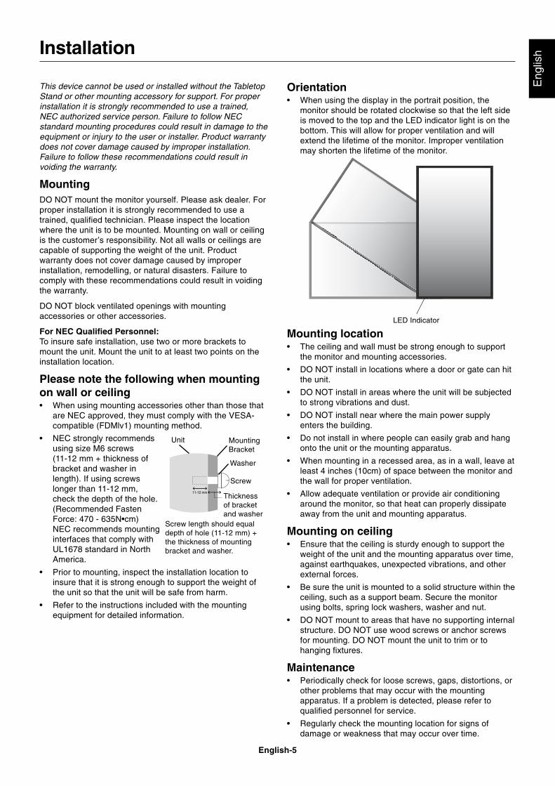
• NEC strongly recommendsusing size M6 screws(11-12 mm + thickness ofbracket and washer inlength). If using screwslonger than 11-12 mm,check the depth of the hole.(Recommended FastenForce: 470 - 635N•cm)NEC recommends mountinginterfaces that comply withUL1678 standard in NorthAmerica.
• Prior to mounting, inspect the installation location toinsure that it is strong enough to support the weight ofthe unit so that the unit will be safe from harm.
• Refer to the instructions included with the mountingequipment for detailed information.
Installation
Mounting location• The ceiling and wall must be strong enough to support
the monitor and mounting accessories.
• DO NOT install in locations where a door or gate can hitthe unit.
• DO NOT install in areas where the unit will be subjectedto strong vibrations and dust.
• DO NOT install near where the main power supplyenters the building.
• Do not install in where people can easily grab and hangonto the unit or the mounting apparatus.
• When mounting in a recessed area, as in a wall, leave atleast 4 inches (10cm) of space between the monitor andthe wall for proper ventilation.
• Allow adequate ventilation or provide air conditioningaround the monitor, so that heat can properly dissipateaway from the unit and mounting apparatus.
Mounting on ceiling• Ensure that the ceiling is sturdy enough to support the
weight of the unit and the mounting apparatus over time,against earthquakes, unexpected vibrations, and otherexternal forces.
• Be sure the unit is mounted to a solid structure within theceiling, such as a support beam. Secure the monitorusing bolts, spring lock washers, washer and nut.
• DO NOT mount to areas that have no supporting internalstructure. DO NOT use wood screws or anchor screwsfor mounting. DO NOT mount the unit to trim or tohanging fixtures.
Maintenance• Periodically check for loose screws, gaps, distortions, or
other problems that may occur with the mountingapparatus. If a problem is detected, please refer toqualified personnel for service.
• Regularly check the mounting location for signs ofdamage or weakness that may occur over time.
Orientation• When using the display in the portrait position, the
monitor should be rotated clockwise so that the left sideis moved to the top and the LED indicator light is on thebottom. This will allow for proper ventilation and willextend the lifetime of the monitor. Improper ventilationmay shorten the lifetime of the monitor.
MountingBracket
Screw
Washer
Unit
11-12 mmThicknessof bracketand washer
Screw length should equaldepth of hole (11-12 mm) +the thickness of mountingbracket and washer.
LED Indicator
English-6
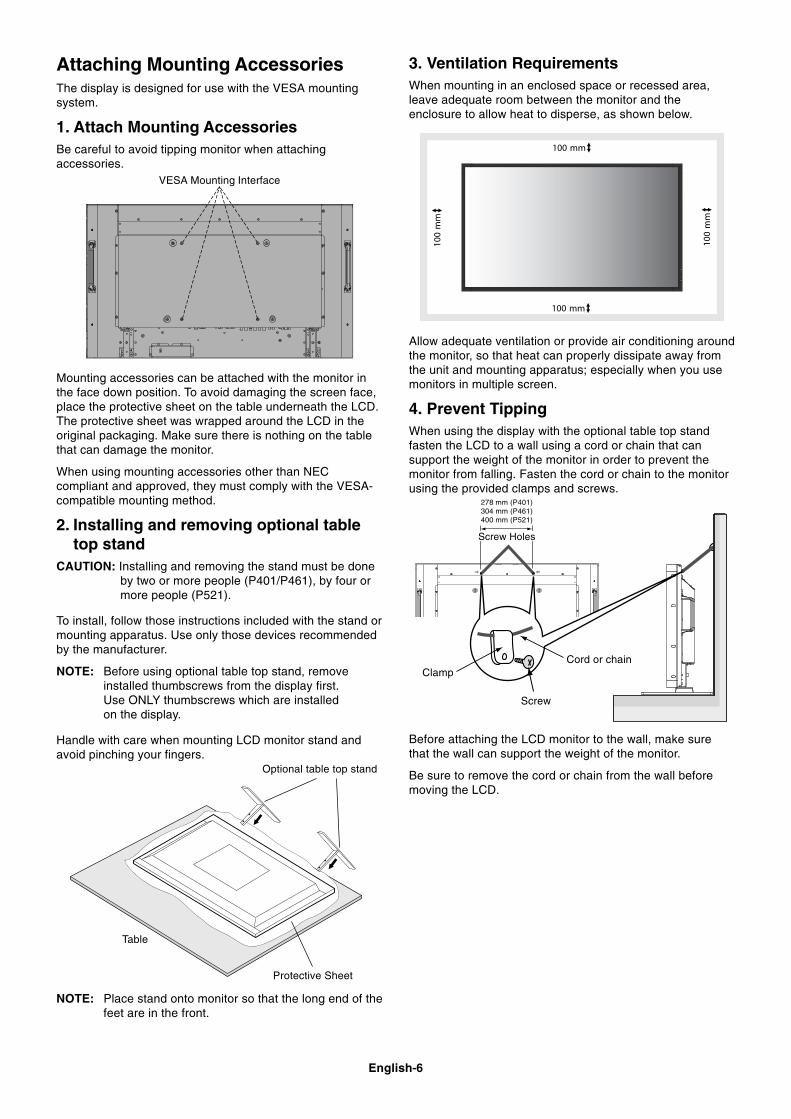
Attaching Mounting AccessoriesThe display is designed for use with the VESA mountingsystem.
1. Attach Mounting AccessoriesBe careful to avoid tipping monitor when attachingaccessories.
Mounting accessories can be attached with the monitor inthe face down position. To avoid damaging the screen face,place the protective sheet on the table underneath the LCD.The protective sheet was wrapped around the LCD in theoriginal packaging. Make sure there is nothing on the tablethat can damage the monitor.
When using mounting accessories other than NECcompliant and approved, they must comply with the VESA-compatible mounting method.
2. Installing and removing optional tabletop stand
CAUTION: Installing and removing the stand must be doneby two or more people (P401/P461), by four ormore people (P521).
To install, follow those instructions included with the stand ormounting apparatus. Use only those devices recommendedby the manufacturer.
NOTE: Before using optional table top stand, removeinstalled thumbscrews from the display first.Use ONLY thumbscrews which are installedon the display.
Handle with care when mounting LCD monitor stand andavoid pinching your fingers.
Screw
Cord or chainClamp
Allow adequate ventilation or provide air conditioning aroundthe monitor, so that heat can properly dissipate away fromthe unit and mounting apparatus; especially when you usemonitors in multiple screen.
4. Prevent TippingWhen using the display with the optional table top standfasten the LCD to a wall using a cord or chain that cansupport the weight of the monitor in order to prevent themonitor from falling. Fasten the cord or chain to the monitorusing the provided clamps and screws.
278 mm (P401)304 mm (P461)400 mm (P521)
3. Ventilation RequirementsWhen mounting in an enclosed space or recessed area,leave adequate room between the monitor and theenclosure to allow heat to disperse, as shown below.
Optional table top stand
Table
Protective Sheet
Before attaching the LCD monitor to the wall, make surethat the wall can support the weight of the monitor.
Be sure to remove the cord or chain from the wall beforemoving the LCD.
Screw Holes
NOTE: Place stand onto monitor so that the long end of thefeet are in the front.
VESA Mounting Interface
English-7
Eng
lish
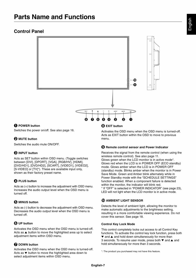
EXIT button
Activates the OSD menu when the OSD menu is turned-off.Acts as EXIT button within the OSD to move to previousmenu.
Remote control sensor and Power Indicator
Receives the signal from the remote control (when using thewireless remote control). See also page 11.Glows green when the LCD monitor is in active mode*.Glows red when the LCD is in POWER OFF (ECO standby)mode. Glows amber when the LCD is in POWER OFF(standby) mode. Blinks amber when the monitor is in PowerSave Mode. Green and Amber blink alternately while inPower Standby mode with the “SCHEDULE SETTINGS”function enabled. When a component failure is detectedwithin the monitor, the indicator will blink red.* If “OFF” is selected in “POWER INDICATOR” (see page 23),LED will not light when the LCD monitor is in active mode.
AMBIENT LIGHT SENSOR
Detects the level of ambient light, allowing the monitor tomake automatic adjustments to the brightness setting,resulting in a more comfortable viewing experience. Do notcover this sensor. See page 18.
Control Key Lock Mode
This control completely locks out access to all Control Keyfunctions. To activate the control key lock function, press both
and and hold down simultaneously for more than3 seconds. To resume user mode, press both and andhold simultaneously for more than 3 seconds.
*: The product you purchased may not have this feature.
POWER button
Switches the power on/off. See also page 16.
MUTE button
Switches the audio mute ON/OFF.
INPUT button
Acts as SET button within OSD menu. (Toggle switchesbetween [DVI], [DPORT], [VGA], [RGB/HV], [HDMI],[DVD/HD1], [DVD/HD2], [SCART], [VIDEO1], [VIDEO2],[S-VIDEO] or [TV]*). These are available input only,shown as their factory preset name.
PLUS button
Acts as (+) button to increase the adjustment with OSD menu.Increases the audio output level when the OSD menu isturned off.
MINUS button
Acts as (-) button to decrease the adjustment with OSD menu.Decreases the audio output level when the OSD menu isturned off.
UP button
Activates the OSD menu when the OSD menu is turned-off.Acts as button to move the highlighted area up to selectadjustment items within OSD menu.
DOWN button
Activates the OSD menu when the OSD menu is turned-off.Acts as button to move the highlighted area down toselect adjustment items within OSD menu.
Control Panel
Parts Name and Functions
English-8
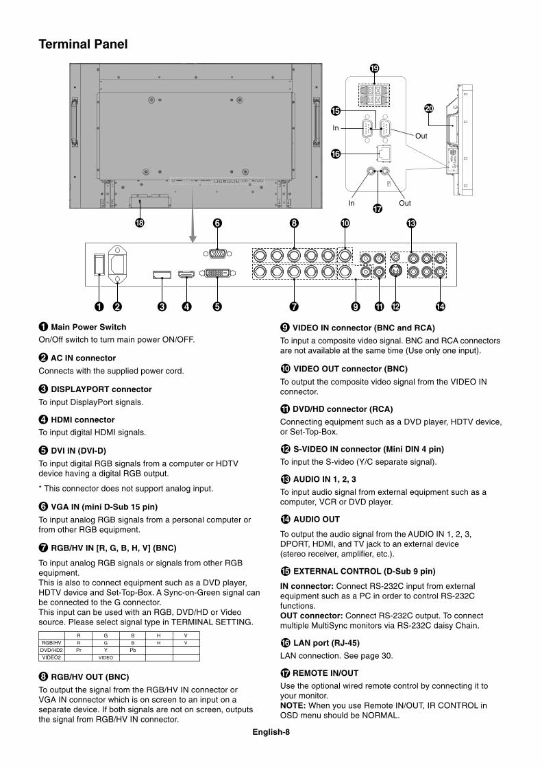
Terminal Panel
OutIn
OutIn
R G B H V
RGB/HV R G B H V
DVD/HD2 Pr Y Pb
VIDEO2 VIDEO
VIDEO IN connector (BNC and RCA)
To input a composite video signal. BNC and RCA connectorsare not available at the same time (Use only one input).
VIDEO OUT connector (BNC)
To output the composite video signal from the VIDEO INconnector.
DVD/HD connector (RCA)
Connecting equipment such as a DVD player, HDTV device,or Set-Top-Box.
S-VIDEO IN connector (Mini DIN 4 pin)
To input the S-video (Y/C separate signal).
AUDIO IN 1, 2, 3
To input audio signal from external equipment such as acomputer, VCR or DVD player.
AUDIO OUT
To output the audio signal from the AUDIO IN 1, 2, 3,DPORT, HDMI, and TV jack to an external device(stereo receiver, amplifier, etc.).
EXTERNAL CONTROL (D-Sub 9 pin)
IN connector: Connect RS-232C input from externalequipment such as a PC in order to control RS-232Cfunctions.OUT connector: Connect RS-232C output. To connectmultiple MultiSync monitors via RS-232C daisy Chain.
LAN port (RJ-45)
LAN connection. See page 30.
REMOTE IN/OUT
Use the optional wired remote control by connecting it toyour monitor.NOTE: When you use Remote IN/OUT, IR CONTROL inOSD menu should be NORMAL.
Main Power Switch
On/Off switch to turn main power ON/OFF.
AC IN connector
Connects with the supplied power cord.
DISPLAYPORT connector
To input DisplayPort signals.
HDMI connector
To input digital HDMI signals.
DVI IN (DVI-D)
To input digital RGB signals from a computer or HDTVdevice having a digital RGB output.
* This connector does not support analog input.
VGA IN (mini D-Sub 15 pin)
To input analog RGB signals from a personal computer orfrom other RGB equipment.
RGB/HV IN [R, G, B, H, V] (BNC)
To input analog RGB signals or signals from other RGBequipment.This is also to connect equipment such as a DVD player,HDTV device and Set-Top-Box. A Sync-on-Green signal canbe connected to the G connector.This input can be used with an RGB, DVD/HD or Videosource. Please select signal type in TERMINAL SETTING.
RGB/HV OUT (BNC)
To output the signal from the RGB/HV IN connector orVGA IN connector which is on screen to an input on aseparate device. If both signals are not on screen, outputsthe signal from RGB/HV IN connector.

English-9
Eng
lish
Kensington Lock
For security and theft prevention.
EXTERNAL SPEAKER TERMINAL
To output the audio signal from AUDIO 1, 2, 3, DPORT,HDMI and TV jack.Note: This speaker terminal is for 15W + 15W (8 ohm)speaker.
Option board slot
Slot for board accessories. Please contact your supplier fordetailed information.
English-10
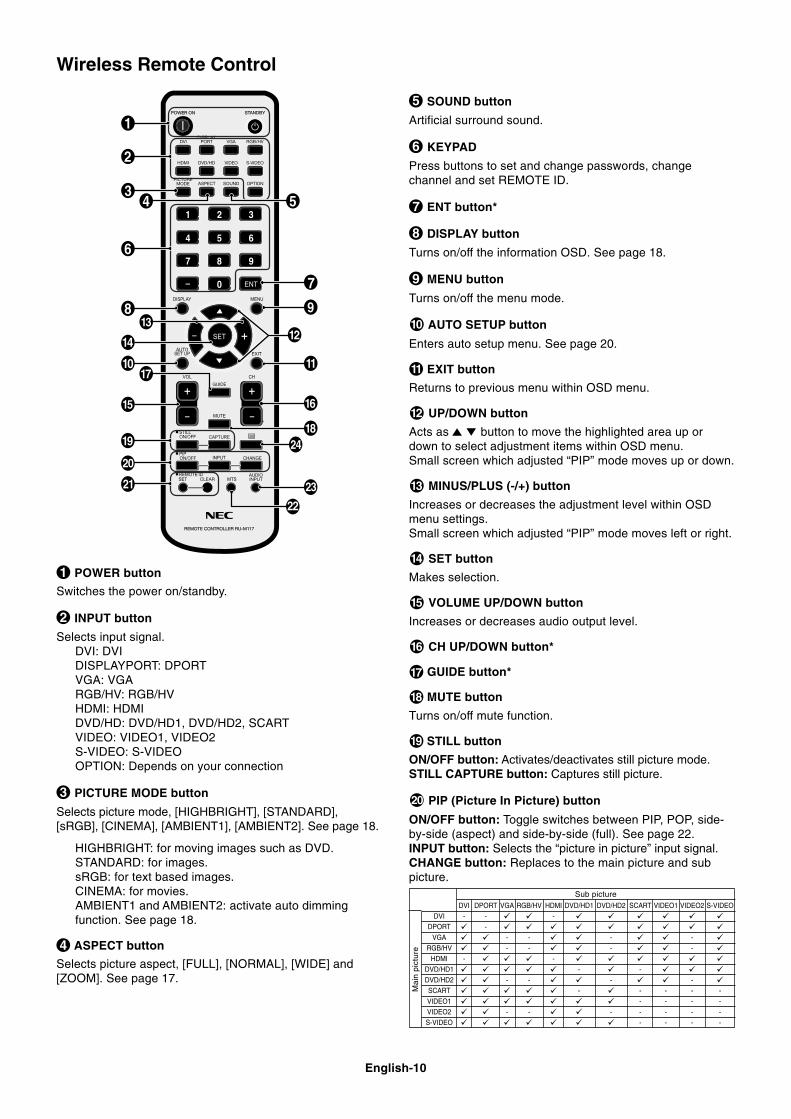
POWER button
Switches the power on/standby.
INPUT button
Selects input signal.DVI: DVIDISPLAYPORT: DPORTVGA: VGARGB/HV: RGB/HVHDMI: HDMIDVD/HD: DVD/HD1, DVD/HD2, SCARTVIDEO: VIDEO1, VIDEO2S-VIDEO: S-VIDEOOPTION: Depends on your connection
PICTURE MODE button
Selects picture mode, [HIGHBRIGHT], [STANDARD],[sRGB], [CINEMA], [AMBIENT1], [AMBIENT2]. See page 18.
HIGHBRIGHT: for moving images such as DVD.STANDARD: for images.sRGB: for text based images.CINEMA: for movies.AMBIENT1 and AMBIENT2: activate auto dimmingfunction. See page 18.
ASPECT button
Selects picture aspect, [FULL], [NORMAL], [WIDE] and[ZOOM]. See page 17.
SOUND button
Artificial surround sound.
KEYPAD
Press buttons to set and change passwords, changechannel and set REMOTE ID.
ENT button*
DISPLAY button
Turns on/off the information OSD. See page 18.
MENU button
Turns on/off the menu mode.
AUTO SETUP button
Enters auto setup menu. See page 20.
EXIT button
Returns to previous menu within OSD menu.
UP/DOWN button
Acts as button to move the highlighted area up ordown to select adjustment items within OSD menu.Small screen which adjusted “PIP” mode moves up or down.
MINUS/PLUS (-/+) button
Increases or decreases the adjustment level within OSDmenu settings.Small screen which adjusted “PIP” mode moves left or right.
SET button
Makes selection.
VOLUME UP/DOWN button
Increases or decreases audio output level.
CH UP/DOWN button*
GUIDE button*
MUTE button
Turns on/off mute function.
STILL button
ON/OFF button: Activates/deactivates still picture mode.STILL CAPTURE button: Captures still picture.
PIP (Picture In Picture) button
ON/OFF button: Toggle switches between PIP, POP, side-by-side (aspect) and side-by-side (full). See page 22.INPUT button: Selects the “picture in picture” input signal.CHANGE button: Replaces to the main picture and subpicture.
Wireless Remote Control
DVI DPORT VGA RGB/HV HDMI DVD/HD1 DVD/HD2 SCART VIDEO1 VIDEO2 S-VIDEO
DVI - - -
DPORT -
VGA - - - -
RGB/HV - - - -
HDMI - -
DVD/HD1 - -
DVD/HD2 - - - -
SCART - - - - -
VIDEO1 - - - -
VIDEO2 - - - - - - -
S-VIDEO - - - -
Sub picture
Mai
n pi
ctur
e
English-11
Eng
lish
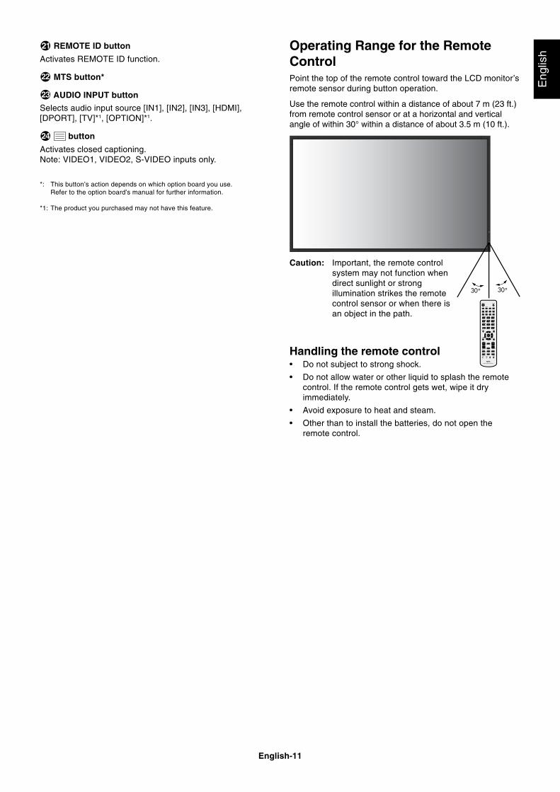
Operating Range for the RemoteControlPoint the top of the remote control toward the LCD monitor’sremote sensor during button operation.
Use the remote control within a distance of about 7 m (23 ft.)from remote control sensor or at a horizontal and verticalangle of within 30° within a distance of about 3.5 m (10 ft.).
Caution: Important, the remote controlsystem may not function whendirect sunlight or strongillumination strikes the remotecontrol sensor or when there isan object in the path.
Handling the remote control• Do not subject to strong shock.
• Do not allow water or other liquid to splash the remotecontrol. If the remote control gets wet, wipe it dryimmediately.
• Avoid exposure to heat and steam.
• Other than to install the batteries, do not open theremote control.
REMOTE ID button
Activates REMOTE ID function.
MTS button*
AUDIO INPUT button
Selects audio input source [IN1], [IN2], [IN3], [HDMI],[DPORT], [TV]*1, [OPTION]*1.
button
Activates closed captioning.Note: VIDEO1, VIDEO2, S-VIDEO inputs only.
*: This button’s action depends on which option board you use.Refer to the option board’s manual for further information.
*1: The product you purchased may not have this feature.
English-12
1. Determine the installation locationCAUTION: Installing your LCD display must be done by a
qualified technician. Contact your dealer formore information.
CAUTION: MOVING OR INSTALLING THE LCD MONITORMUST BE DONE BY TWO OR MORE PEOPLE(P401/P461), BY FOUR OR MORE PEOPLE(P521). Failure to follow this caution may result ininjury if the LCD monitor falls.
CAUTION: Do not mount or operate the display upsidedown, face up, or face down.
CAUTION: This LCD has a temperature sensor and coolingfan. If the LCD becomes too hot, the cooling fanwill turn on automatically. If the LCD becomesoverheated while the cooling fan is running, a“Caution” warning will appear. If the “Caution”warning appears, discontinue use and allow theunit to cool. Using the cooling fan will reduce thelikelihood of early circuit failure and may helpreduce image degradation and “ImagePersistance”.If the LCD is used in an enclosed area or if theLCD panel is covered with a protective screen,please check the inside temperature of themonitor by using the “HEAT STATUS” control inthe OSD (see page 24). If the temperature ishigher than the normal operating temperature,please turn the cooling fan to ON within the FANCONTROL menu within the OSD (see page 24).
IMPORTANT: Lay the protective sheet, which was wrappedaround the LCD monitor when it waspackaged, beneath the LCD monitor so asnot to scratch the panel.
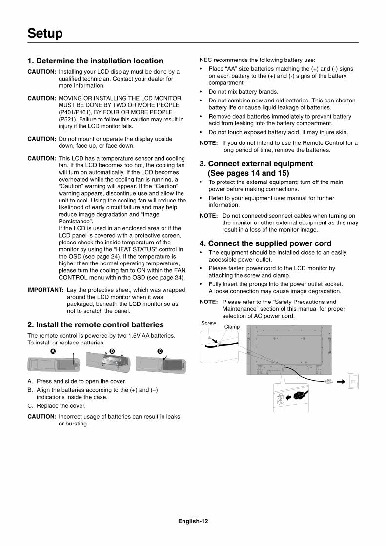
2. Install the remote control batteriesThe remote control is powered by two 1.5V AA batteries.To install or replace batteries:
NEC recommends the following battery use:
• Place “AA” size batteries matching the (+) and (-) signson each battery to the (+) and (-) signs of the batterycompartment.
• Do not mix battery brands.
• Do not combine new and old batteries. This can shortenbattery life or cause liquid leakage of batteries.
• Remove dead batteries immediately to prevent batteryacid from leaking into the battery compartment.
• Do not touch exposed battery acid, it may injure skin.
NOTE: If you do not intend to use the Remote Control for along period of time, remove the batteries.
3. Connect external equipment(See pages 14 and 15)
• To protect the external equipment; turn off the mainpower before making connections.
• Refer to your equipment user manual for furtherinformation.
NOTE: Do not connect/disconnect cables when turning onthe monitor or other external equipment as this mayresult in a loss of the monitor image.
4. Connect the supplied power cord• The equipment should be installed close to an easily
accessible power outlet.
• Please fasten power cord to the LCD monitor byattaching the screw and clamp.
• Fully insert the prongs into the power outlet socket.A loose connection may cause image degradation.
NOTE: Please refer to the “Safety Precautions andMaintenance” section of this manual for properselection of AC power cord.
Setup
A. Press and slide to open the cover.
B. Align the batteries according to the (+) and (–)indications inside the case.
C. Replace the cover.
CAUTION: Incorrect usage of batteries can result in leaksor bursting.
ScrewClamp
English-13
Eng
lish
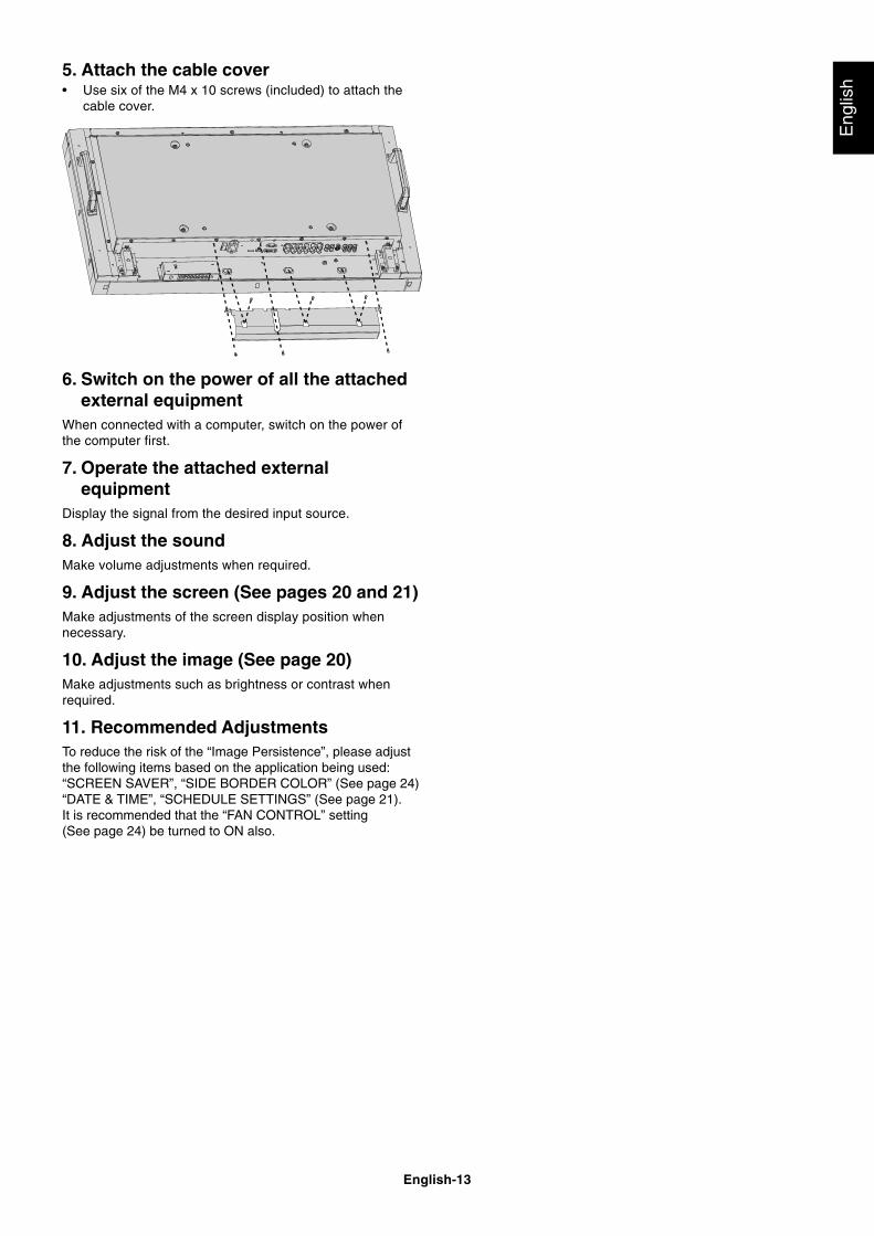
6. Switch on the power of all the attachedexternal equipment
When connected with a computer, switch on the power ofthe computer first.
7. Operate the attached externalequipment
Display the signal from the desired input source.
8. Adjust the soundMake volume adjustments when required.
9. Adjust the screen (See pages 20 and 21)Make adjustments of the screen display position whennecessary.
10. Adjust the image (See page 20)Make adjustments such as brightness or contrast whenrequired.
11. Recommended AdjustmentsTo reduce the risk of the “Image Persistence”, please adjustthe following items based on the application being used:“SCREEN SAVER”, “SIDE BORDER COLOR” (See page 24)“DATE & TIME”, “SCHEDULE SETTINGS” (See page 21).It is recommended that the “FAN CONTROL” setting(See page 24) be turned to ON also.
5. Attach the cable cover• Use six of the M4 x 10 screws (included) to attach the
cable cover.
English-14
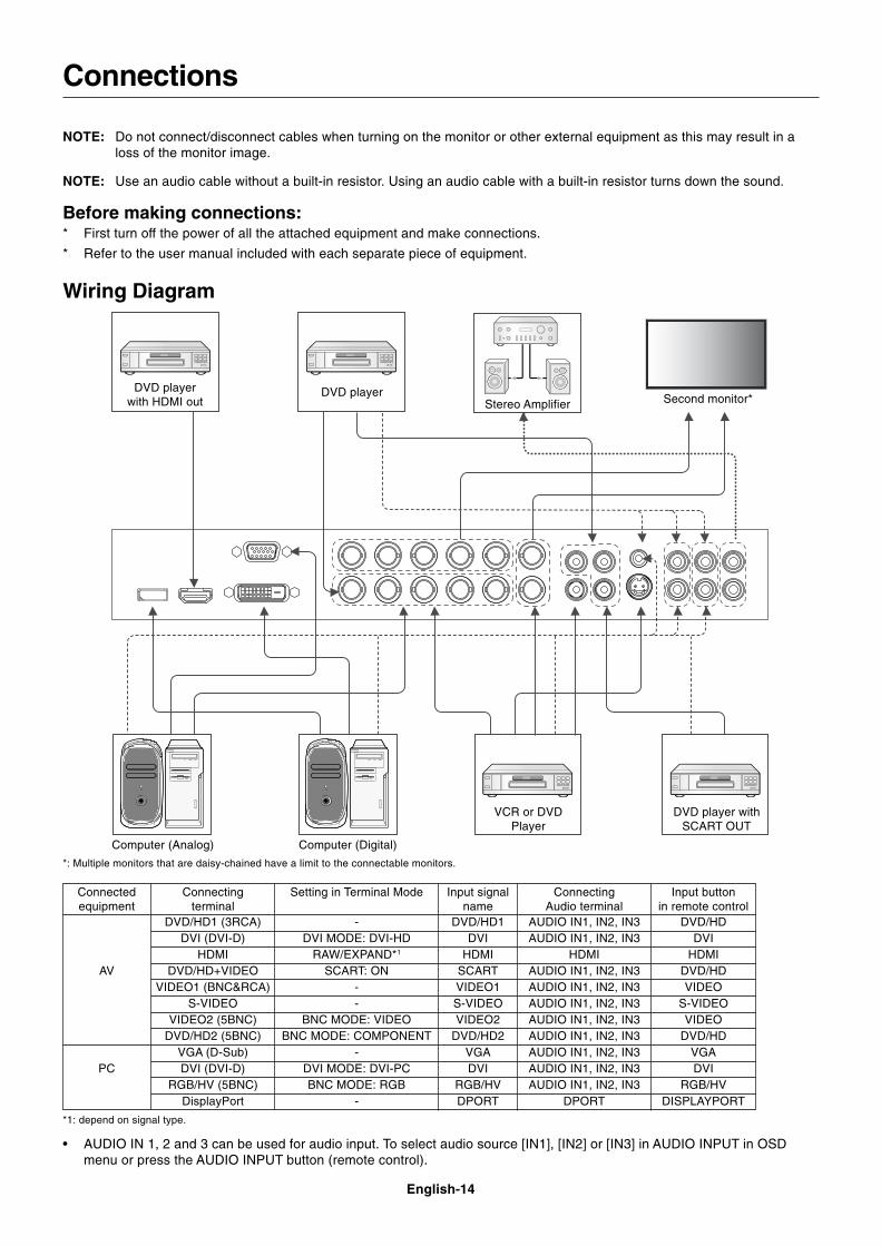
Connections
NOTE: Do not connect/disconnect cables when turning on the monitor or other external equipment as this may result in aloss of the monitor image.
NOTE: Use an audio cable without a built-in resistor. Using an audio cable with a built-in resistor turns down the sound.
Before making connections:* First turn off the power of all the attached equipment and make connections.
* Refer to the user manual included with each separate piece of equipment.
Wiring Diagram
DVD playerwith HDMI out
DVD player
VCR or DVDPlayer
Stereo Amplifier Second monitor*
Computer (Analog) Computer (Digital)
DVD player withSCART OUT
Connectingterminal
DVD/HD1 (3RCA)DVI (DVI-D)
HDMIDVD/HD+VIDEO
VIDEO1 (BNC&RCA)S-VIDEO
VIDEO2 (5BNC)DVD/HD2 (5BNC)
VGA (D-Sub)DVI (DVI-D)
RGB/HV (5BNC)DisplayPort
Setting in Terminal Mode
-DVI MODE: DVI-HD
RAW/EXPAND*1
SCART: ON--
BNC MODE: VIDEOBNC MODE: COMPONENT
-DVI MODE: DVI-PCBNC MODE: RGB
-
Input signalname
DVD/HD1DVI
HDMISCARTVIDEO1S-VIDEOVIDEO2
DVD/HD2VGADVI
RGB/HVDPORT
ConnectingAudio terminal
AUDIO IN1, IN2, IN3AUDIO IN1, IN2, IN3
HDMIAUDIO IN1, IN2, IN3AUDIO IN1, IN2, IN3AUDIO IN1, IN2, IN3AUDIO IN1, IN2, IN3AUDIO IN1, IN2, IN3AUDIO IN1, IN2, IN3AUDIO IN1, IN2, IN3AUDIO IN1, IN2, IN3
DPORT
Input buttonin remote control
DVD/HDDVI
HDMIDVD/HDVIDEO
S-VIDEOVIDEO
DVD/HDVGADVI
RGB/HVDISPLAYPORT
Connectedequipment
AV
PC
• AUDIO IN 1, 2 and 3 can be used for audio input. To select audio source [IN1], [IN2] or [IN3] in AUDIO INPUT in OSDmenu or press the AUDIO INPUT button (remote control).
*1: depend on signal type.
*: Multiple monitors that are daisy-chained have a limit to the connectable monitors.
English-15
Eng
lish
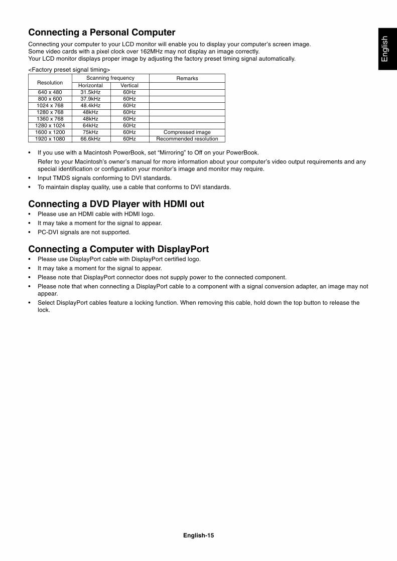
Connecting a Personal ComputerConnecting your computer to your LCD monitor will enable you to display your computer’s screen image.Some video cards with a pixel clock over 162MHz may not display an image correctly.Your LCD monitor displays proper image by adjusting the factory preset timing signal automatically.
<Factory preset signal timing>
• If you use with a Macintosh PowerBook, set “Mirroring” to Off on your PowerBook.
Refer to your Macintosh’s owner’s manual for more information about your computer’s video output requirements and anyspecial identification or configuration your monitor’s image and monitor may require.
• Input TMDS signals conforming to DVI standards.
• To maintain display quality, use a cable that conforms to DVI standards.
Connecting a DVD Player with HDMI out• Please use an HDMI cable with HDMI logo.
• It may take a moment for the signal to appear.
• PC-DVI signals are not supported.
Connecting a Computer with DisplayPort• Please use DisplayPort cable with DisplayPort certified logo.
• It may take a moment for the signal to appear.
• Please note that DisplayPort connector does not supply power to the connected component.
• Please note that when connecting a DisplayPort cable to a component with a signal conversion adapter, an image may notappear.
• Select DisplayPort cables feature a locking function. When removing this cable, hold down the top button to release thelock.
Horizontal Vertical640 x 480 31.5kHz 60Hz800 x 600 37.9kHz 60Hz1024 x 768 48.4kHz 60Hz1280 x 768 48kHz 60Hz1360 x 768 48kHz 60Hz
1280 x 1024 64kHz 60Hz1600 x 1200 75kHz 60Hz Compressed image1920 x 1080 66.6kHz 60Hz Recommended resolution
ResolutionRemarksScanning frequency
English-16
Basic Operation
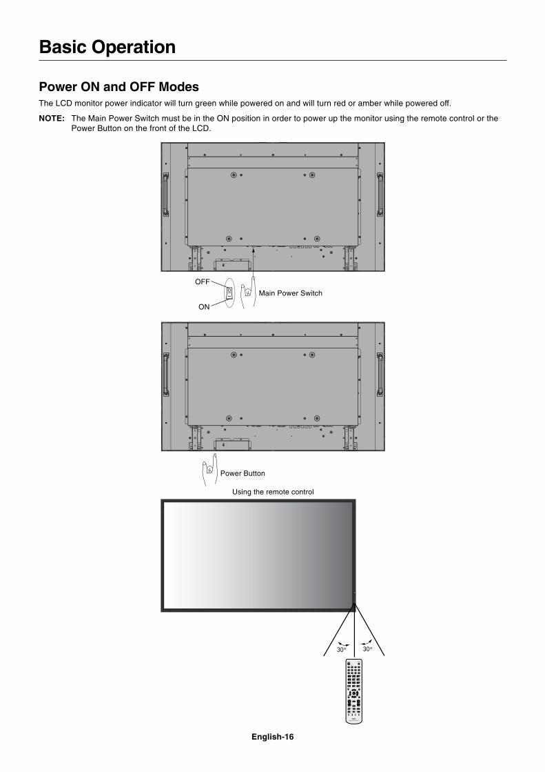
Power ON and OFF ModesThe LCD monitor power indicator will turn green while powered on and will turn red or amber while powered off.
NOTE: The Main Power Switch must be in the ON position in order to power up the monitor using the remote control or thePower Button on the front of the LCD.
Power Button
Main Power Switch
ON
OFF
Using the remote control
English-17
Eng
lish
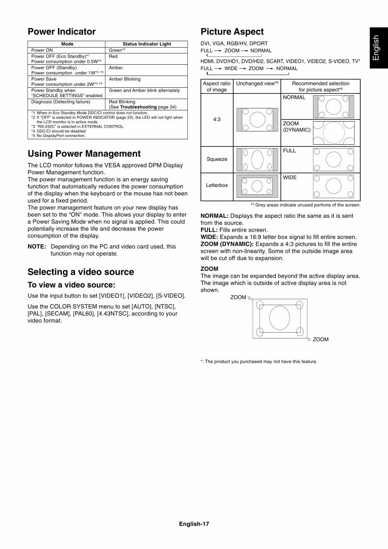
NORMAL: Displays the aspect ratio the same as it is sentfrom the source.FULL: Fills entire screen.WIDE: Expands a 16:9 letter box signal to fill entire screen.ZOOM (DYNAMIC): Expands a 4:3 pictures to fill the entirescreen with non-linearity. Some of the outside image areawill be cut off due to expansion.
ZOOMThe image can be expanded beyond the active display area.The image which is outside of active display area is notshown.
ZOOM
ZOOM
Using Power ManagementThe LCD monitor follows the VESA approved DPM DisplayPower Management function.The power management function is an energy savingfunction that automatically reduces the power consumptionof the display when the keyboard or the mouse has not beenused for a fixed period.The power management feature on your new display hasbeen set to the “ON” mode. This allows your display to entera Power Saving Mode when no signal is applied. This couldpotentially increase the life and decrease the powerconsumption of the display.
NOTE: Depending on the PC and video card used, thisfunction may not operate.
Selecting a video sourceTo view a video source:Use the input button to set [VIDEO1], [VIDEO2], [S-VIDEO].
Use the COLOR SYSTEM menu to set [AUTO], [NTSC],[PAL], [SECAM], [PAL60], [4.43NTSC], according to yourvideo format.
Aspect ratioof image
NORMAL
ZOOM(DYNAMIC)
FULL
WIDE
4:3
Squeeze
Letterbox
Unchanged view*6 Recommended selectionfor picture aspect*6
*6 Grey areas indicate unused portions of the screen.
Power IndicatorMode Status Indicator Light
Power ON Green*2
Power OFF (Eco Standby)*1 RedPower consumption under 0.5W*3
Power OFF (Standby) AmberPower consumption under 1W*3, *4
Power Save Amber BlinkingPower consumption under 2W*3, *5
Power Standby when Green and Amber blink alternately“SCHEDULE SETTINGS” enabledDiagnosis (Detecting failure) Red Blinking
(See Troubleshooting page 34)*1 When in Eco Standby Mode DDC/CI control does not function.*2 If “OFF” is selected in POWER INDICATOR (page 23), the LED will not light when
the LCD monitor is in active mode.*3 “RS-232C” is selected in EXTERNAL CONTROL.*4 DDC/CI should be disabled.*5 No DisplayPort connection.
Picture AspectDVI, VGA, RGB/HV, DPORTFULL ZOOM NORMAL
HDMI, DVD/HD1, DVD/HD2, SCART, VIDEO1, VIDEO2, S-VIDEO, TV*FULL WIDE ZOOM NORMAL
*: The product you purchased may not have this feature.
English-18
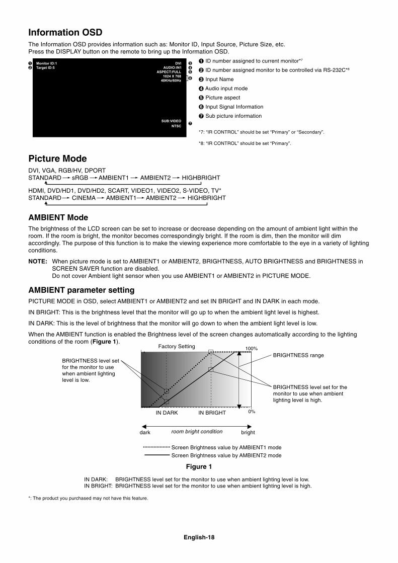
BRIGHTNESS level setfor the monitor to usewhen ambient lightinglevel is low.
BRIGHTNESS level set for themonitor to use when ambientlighting level is high.
BRIGHTNESS range
IN DARK: BRIGHTNESS level set for the monitor to use when ambient lighting level is low.IN BRIGHT: BRIGHTNESS level set for the monitor to use when ambient lighting level is high.
Figure 1
dark brightroom bright condition
Screen Brightness value by AMBIENT2 mode
Picture ModeDVI, VGA, RGB/HV, DPORTSTANDARD sRGB AMBIENT1 AMBIENT2 HIGHBRIGHT
HDMI, DVD/HD1, DVD/HD2, SCART, VIDEO1, VIDEO2, S-VIDEO, TV*STANDARD CINEMA AMBIENT1 AMBIENT2 HIGHBRIGHT
AMBIENT ModeThe brightness of the LCD screen can be set to increase or decrease depending on the amount of ambient light within theroom. If the room is bright, the monitor becomes correspondingly bright. If the room is dim, then the monitor will dimaccordingly. The purpose of this function is to make the viewing experience more comfortable to the eye in a variety of lightingconditions.
NOTE: When picture mode is set to AMBIENT1 or AMBIENT2, BRIGHTNESS, AUTO BRIGHTNESS and BRIGHTNESS inSCREEN SAVER function are disabled.Do not cover Ambient light sensor when you use AMBIENT1 or AMBIENT2 in PICTURE MODE.
AMBIENT parameter settingPICTURE MODE in OSD, select AMBIENT1 or AMBIENT2 and set IN BRIGHT and IN DARK in each mode.
IN BRIGHT: This is the brightness level that the monitor will go up to when the ambient light level is highest.
IN DARK: This is the level of brightness that the monitor will go down to when the ambient light level is low.
When the AMBIENT function is enabled the Brightness level of the screen changes automatically according to the lightingconditions of the room (Figure 1).
IN DARK IN BRIGHT
Information OSDThe Information OSD provides information such as: Monitor ID, Input Source, Picture Size, etc.Press the DISPLAY button on the remote to bring up the Information OSD.
ID number assigned to current monitor*7
ID number assigned monitor to be controlled via RS-232C*8
Input Name
Audio input mode
Picture aspect
Input Signal Information
Sub picture information
*7: “IR CONTROL” should be set “Primary” or “Secondary”.
*8: “IR CONTROL” should be set “Primary”.
*: The product you purchased may not have this feature.
Screen Brightness value by AMBIENT1 mode
Factory Setting
English-19
Eng
lishOSD (On-Screen-Display) Controls
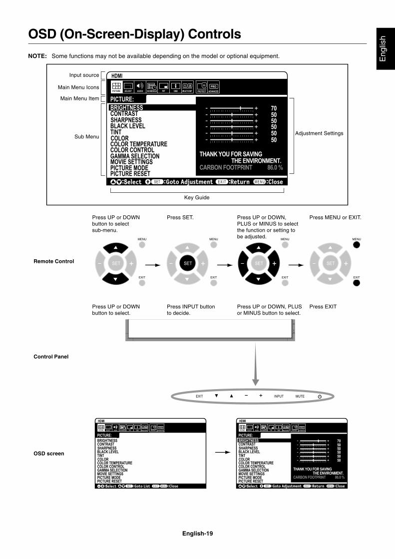
Press UP or DOWNbutton to selectsub-menu.
Press SET. Press UP or DOWN,PLUS or MINUS to selectthe function or setting tobe adjusted.
Press MENU or EXIT.
Remote Control
Press UP or DOWNbutton to select.
Press INPUT buttonto decide.
Press UP or DOWN, PLUSor MINUS button to select.
Press EXIT
Control Panel
OSD screen
PICTURE MODE
Goto AdjustmentSelect Return Close
705050505050
THANK YOU FOR SAVING THE ENVIRONMENT.CARBON FOOTPRINT 86.0 %
Input source
Main Menu Icons
Main Menu Item
Sub Menu
Key Guide
Adjustment Settings
NOTE: Some functions may not be available depending on the model or optional equipment.
English-20
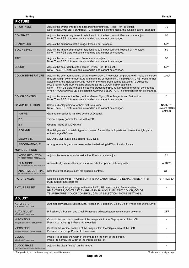
Setting Default
BRIGHTNESS Adjusts the overall image and background brightness. Press + or - to adjust. 70Note: When AMBIENT1 or AMBIENT2 is selected in picture mode, this function cannot changed.
CONTRAST Adjusts the image brightness in relationship to the background. Press + or - to adjust. 50Note: The sRGB picture mode is standard and cannot be changed.
SHARPNESS Adjusts the crispness of the image. Press + or - to adjust. 50*2
BLACK LEVEL Adjusts the image brightness in relationship to the background. Press + or - to adjust. 50Note: The sRGB picture mode is standard and cannot be changed.
TINT Adjusts the tint of the screen. Press + or - to adjust. 50Note: The sRGB picture mode is standard and cannot be changed.
COLOR Adjusts the color depth of the screen. Press + or - to adjust. 50*2
Note: The sRGB picture mode is standard and cannot be changed.
COLOR TEMPERATURE Adjusts the color temperature of the entire screen. A low color temperature will make the screen 10000Kreddish. A high color temperature will make the screen bluish. If TEMPERATURE needs furtheradjustment, the individual R/G/B/ levels of the white point can be adjusted. To adjust theR/G/B levels, CUSTOM must be showing as the COLOR TEMP selection.Note: The sRGB picture mode is set to a predefined 6500 K standard and cannot be changed.When PROGRAMMABLE is selected in GAMMA SELECTION, this function cannot be changed.
COLOR CONTROL Adjusts the levels of the Red, Yellow, Green, Cyan, Blue, Magenta and Saturation. 0Note: The sRGB picture mode is standard and cannot be changed.
GAMMA SELECTION Select a display gamma for best picture quality. NATIVE*2
Note: The sRGB picture mode is standard and cannot be changed. (except sRGB
NATIVE Gamma correction is handled by the LCD panel.
2.2 Typical display gamma for use with a PC.
2.4 Good for video (TV, DVD, etc.)
S GAMMA Special gamma for certain types of movies. Raises the dark parts and lowers the light partsof the image (S-Curve).
DICOM SIM. DICOM GSDF curve simulated for LCD type.
PROGRAMMABLE A programmable gamma curve can be loaded using NEC optional software.
MOVIE SETTINGS
NOISE REDUCTION Adjusts the amount of noise reduction. Press + or - to adjust. 6*2
TV, VIDEO1, VIDEO2, S-VIDEO inputs only
FILM MODE Automatically senses the sources frame rate for optimal picture quality. AUTO*2
HDMI, DVD/HD1, DVD/HD2, SCART, VIDEO1, VIDEO2, S-VIDEO, TV* inputs only
ADAPTIVE CONTRAST Sets the level of adjustment for dynamic contrast. OFFHDMI, DVD/HD1, DVD/HD2, SCART, VIDEO1, VIDEO2, S-VIDEO, TV* inputs only
PICTURE MODE Selects picture mode, [HIGHBRIGHT], [STANDARD], [sRGB], [CINEMA], [AMBIENT1] or STANDARD[AMBIENT2]. See page 18.
PICTURE RESET Resets the following settings within the PICTURE menu back to factory setting: -BRIGHTNESS, CONTRAST, SHARPNESS, BLACK LEVEL, TINT, COLOR, COLORTEMPERATURE, COLOR CONTROL , GAMMA SELECTION, MOVIE SETTINGS.
AUTO SETUP Automatically adjusts Screen Size, H position, V position, Clock, Clock Phase and White Level. -VGA, RGB/HV inputs only
AUTO ADJUST H Position, V Position and Clock Phase are adjusted automatically upon power on. OFFVGA, RGB/HV inputs only
H POSITION Controls the horizontal position of the image within the Display area of the LCD. -All inputs except DVI, HDMI, DPORT Press + to move right. Press - to move left.
V POSITION Controls the vertical position of the image within the Display area of the LCD. -All inputs except DVI, HDMI, DPORT Press + to move up. Press - to move down.
CLOCK Press + to expand the width of the image on the right of the screen. -VGA, RGB/HV inputs only Press - to narrow the width of the image on the left.
CLOCK PHASE Adjusts the visual “noise” on the image. -VGA, RGB/HV, DVD/HD1, DVD/HD2, SCART inputs only
*: The product you purchased may not have this feature. *2: depends on signal input
PICTURE
ADJUST
setting)
English-21
Eng
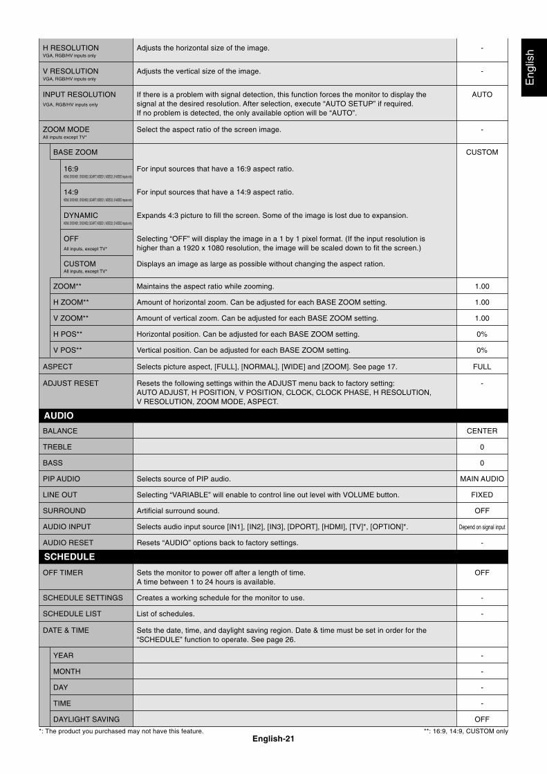
lishH RESOLUTION Adjusts the horizontal size of the image. -
VGA, RGB/HV inputs only
V RESOLUTION Adjusts the vertical size of the image. -VGA, RGB/HV inputs only
INPUT RESOLUTION If there is a problem with signal detection, this function forces the monitor to display the AUTOVGA, RGB/HV inputs only signal at the desired resolution. After selection, execute “AUTO SETUP” if required.
If no problem is detected, the only available option will be “AUTO”.
ZOOM MODE Select the aspect ratio of the screen image. -All inputs except TV*
BASE ZOOM CUSTOM
16:9 For input sources that have a 16:9 aspect ratio.HDMI, DVD/HD1, DVD/HD2, SCART, VIDEO1, VIDEO2, S-VIDEO inputs only
14:9 For input sources that have a 14:9 aspect ratio.HDMI, DVD/HD1, DVD/HD2, SCART, VIDEO1, VIDEO2, S-VIDEO inputs only
DYNAMIC Expands 4:3 picture to fill the screen. Some of the image is lost due to expansion.HDMI, DVD/HD1, DVD/HD2, SCART, VIDEO1, VIDEO2, S-VIDEO inputs only
OFF Selecting “OFF” will display the image in a 1 by 1 pixel format. (If the input resolution isAll inputs, except TV* higher than a 1920 x 1080 resolution, the image will be scaled down to fit the screen.)
CUSTOM Displays an image as large as possible without changing the aspect ration.All inputs, except TV*
ZOOM** Maintains the aspect ratio while zooming. 1.00
H ZOOM** Amount of horizontal zoom. Can be adjusted for each BASE ZOOM setting. 1.00
V ZOOM** Amount of vertical zoom. Can be adjusted for each BASE ZOOM setting. 1.00
H POS** Horizontal position. Can be adjusted for each BASE ZOOM setting. 0%
V POS** Vertical position. Can be adjusted for each BASE ZOOM setting. 0%
ASPECT Selects picture aspect, [FULL], [NORMAL], [WIDE] and [ZOOM]. See page 17. FULL
ADJUST RESET Resets the following settings within the ADJUST menu back to factory setting: -AUTO ADJUST, H POSITION, V POSITION, CLOCK, CLOCK PHASE, H RESOLUTION,V RESOLUTION, ZOOM MODE, ASPECT.
BALANCE CENTER
TREBLE 0
BASS 0
PIP AUDIO Selects source of PIP audio. MAIN AUDIO
LINE OUT Selecting “VARIABLE” will enable to control line out level with VOLUME button. FIXED
SURROUND Artificial surround sound. OFF
AUDIO INPUT Selects audio input source [IN1], [IN2], [IN3], [DPORT], [HDMI], [TV]*, [OPTION]*. Depend on signal input
AUDIO RESET Resets “AUDIO” options back to factory settings. -
OFF TIMER Sets the monitor to power off after a length of time. OFFA time between 1 to 24 hours is available.
SCHEDULE SETTINGS Creates a working schedule for the monitor to use. -
SCHEDULE LIST List of schedules. -
DATE & TIME Sets the date, time, and daylight saving region. Date & time must be set in order for the“SCHEDULE” function to operate. See page 26.
YEAR -
MONTH -
DAY -
TIME -
DAYLIGHT SAVING OFF
*: The product you purchased may not have this feature. **: 16:9, 14:9, CUSTOM only
AUDIO
SCHEDULE
English-22
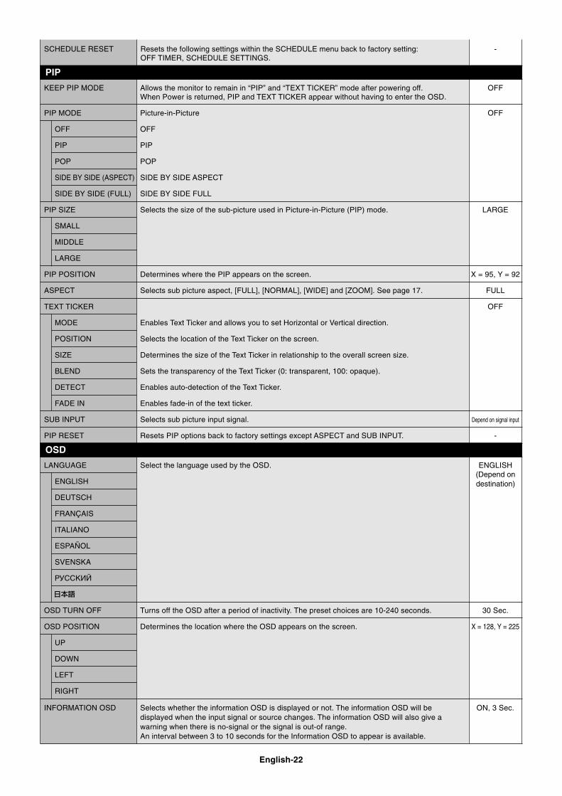
SCHEDULE RESET Resets the following settings within the SCHEDULE menu back to factory setting: -OFF TIMER, SCHEDULE SETTINGS.
KEEP PIP MODE Allows the monitor to remain in “PIP” and “TEXT TICKER” mode after powering off. OFFWhen Power is returned, PIP and TEXT TICKER appear without having to enter the OSD.
PIP MODE Picture-in-Picture OFF
OFF OFF
PIP PIP
POP POP
SIDE BY SIDE (ASPECT) SIDE BY SIDE ASPECT
SIDE BY SIDE (FULL) SIDE BY SIDE FULL
PIP SIZE Selects the size of the sub-picture used in Picture-in-Picture (PIP) mode. LARGE
SMALL
MIDDLE
LARGE
PIP POSITION Determines where the PIP appears on the screen. X = 95, Y = 92
ASPECT Selects sub picture aspect, [FULL], [NORMAL], [WIDE] and [ZOOM]. See page 17. FULL
TEXT TICKER OFF
MODE Enables Text Ticker and allows you to set Horizontal or Vertical direction.
POSITION Selects the location of the Text Ticker on the screen.
SIZE Determines the size of the Text Ticker in relationship to the overall screen size.
BLEND Sets the transparency of the Text Ticker (0: transparent, 100: opaque).
DETECT Enables auto-detection of the Text Ticker.
FADE IN Enables fade-in of the text ticker.
SUB INPUT Selects sub picture input signal. Depend on signal input
PIP RESET Resets PIP options back to factory settings except ASPECT and SUB INPUT. -
LANGUAGE Select the language used by the OSD. ENGLISH
ENGLISH
DEUTSCH
FRANÇAIS
ITALIANO
ESPAÑOL
SVENSKA
РУССКИЙ
OSD TURN OFF Turns off the OSD after a period of inactivity. The preset choices are 10-240 seconds. 30 Sec.
OSD POSITION Determines the location where the OSD appears on the screen. X = 128, Y = 225
UP
DOWN
LEFT
RIGHT
INFORMATION OSD Selects whether the information OSD is displayed or not. The information OSD will be ON, 3 Sec.displayed when the input signal or source changes. The information OSD will also give awarning when there is no-signal or the signal is out-of range.An interval between 3 to 10 seconds for the Information OSD to appear is available.
PIP
OSD
(Depend ondestination)
English-23
Eng
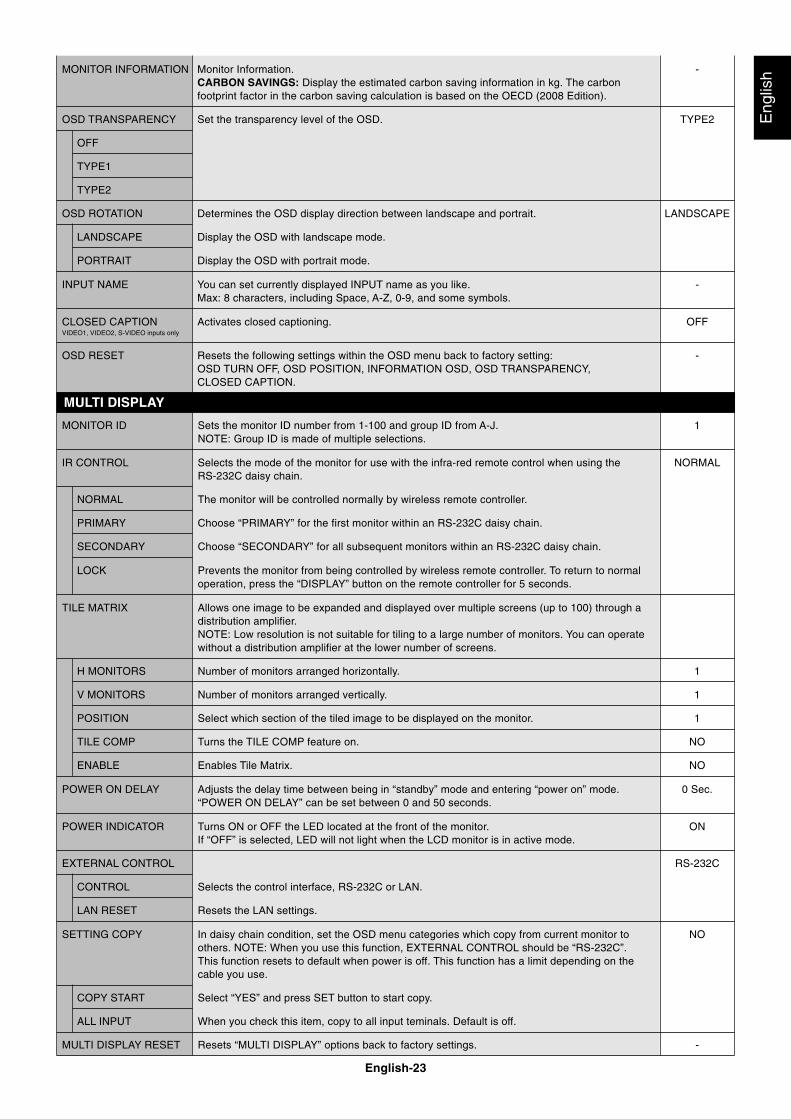
lishMONITOR INFORMATION Monitor Information. -
CARBON SAVINGS: Display the estimated carbon saving information in kg. The carbonfootprint factor in the carbon saving calculation is based on the OECD (2008 Edition).
OSD TRANSPARENCY Set the transparency level of the OSD. TYPE2
OFF
TYPE1
TYPE2
OSD ROTATION Determines the OSD display direction between landscape and portrait. LANDSCAPE
LANDSCAPE Display the OSD with landscape mode.
PORTRAIT Display the OSD with portrait mode.
INPUT NAME You can set currently displayed INPUT name as you like. -Max: 8 characters, including Space, A-Z, 0-9, and some symbols.
CLOSED CAPTION Activates closed captioning. OFFVIDEO1, VIDEO2, S-VIDEO inputs only
OSD RESET Resets the following settings within the OSD menu back to factory setting: -OSD TURN OFF, OSD POSITION, INFORMATION OSD, OSD TRANSPARENCY,CLOSED CAPTION.
MONITOR ID Sets the monitor ID number from 1-100 and group ID from A-J. 1NOTE: Group ID is made of multiple selections.
IR CONTROL Selects the mode of the monitor for use with the infra-red remote control when using the NORMALRS-232C daisy chain.
NORMAL The monitor will be controlled normally by wireless remote controller.
PRIMARY Choose “PRIMARY” for the first monitor within an RS-232C daisy chain.
SECONDARY Choose “SECONDARY” for all subsequent monitors within an RS-232C daisy chain.
LOCK Prevents the monitor from being controlled by wireless remote controller. To return to normaloperation, press the “DISPLAY” button on the remote controller for 5 seconds.
TILE MATRIX Allows one image to be expanded and displayed over multiple screens (up to 100) through adistribution amplifier.NOTE: Low resolution is not suitable for tiling to a large number of monitors. You can operatewithout a distribution amplifier at the lower number of screens.
H MONITORS Number of monitors arranged horizontally. 1
V MONITORS Number of monitors arranged vertically. 1
POSITION Select which section of the tiled image to be displayed on the monitor. 1
TILE COMP Turns the TILE COMP feature on. NO
ENABLE Enables Tile Matrix. NO
POWER ON DELAY Adjusts the delay time between being in “standby” mode and entering “power on” mode. 0 Sec.“POWER ON DELAY” can be set between 0 and 50 seconds.
POWER INDICATOR Turns ON or OFF the LED located at the front of the monitor. ONIf “OFF” is selected, LED will not light when the LCD monitor is in active mode.
EXTERNAL CONTROL RS-232C
CONTROL Selects the control interface, RS-232C or LAN.
LAN RESET Resets the LAN settings.
SETTING COPY In daisy chain condition, set the OSD menu categories which copy from current monitor to NOothers. NOTE: When you use this function, EXTERNAL CONTROL should be “RS-232C”.This function resets to default when power is off. This function has a limit depending on thecable you use.
COPY START Select “YES” and press SET button to start copy.
ALL INPUT When you check this item, copy to all input teminals. Default is off.
MULTI DISPLAY RESET Resets “MULTI DISPLAY” options back to factory settings. -
MULTI DISPLAY
English-24
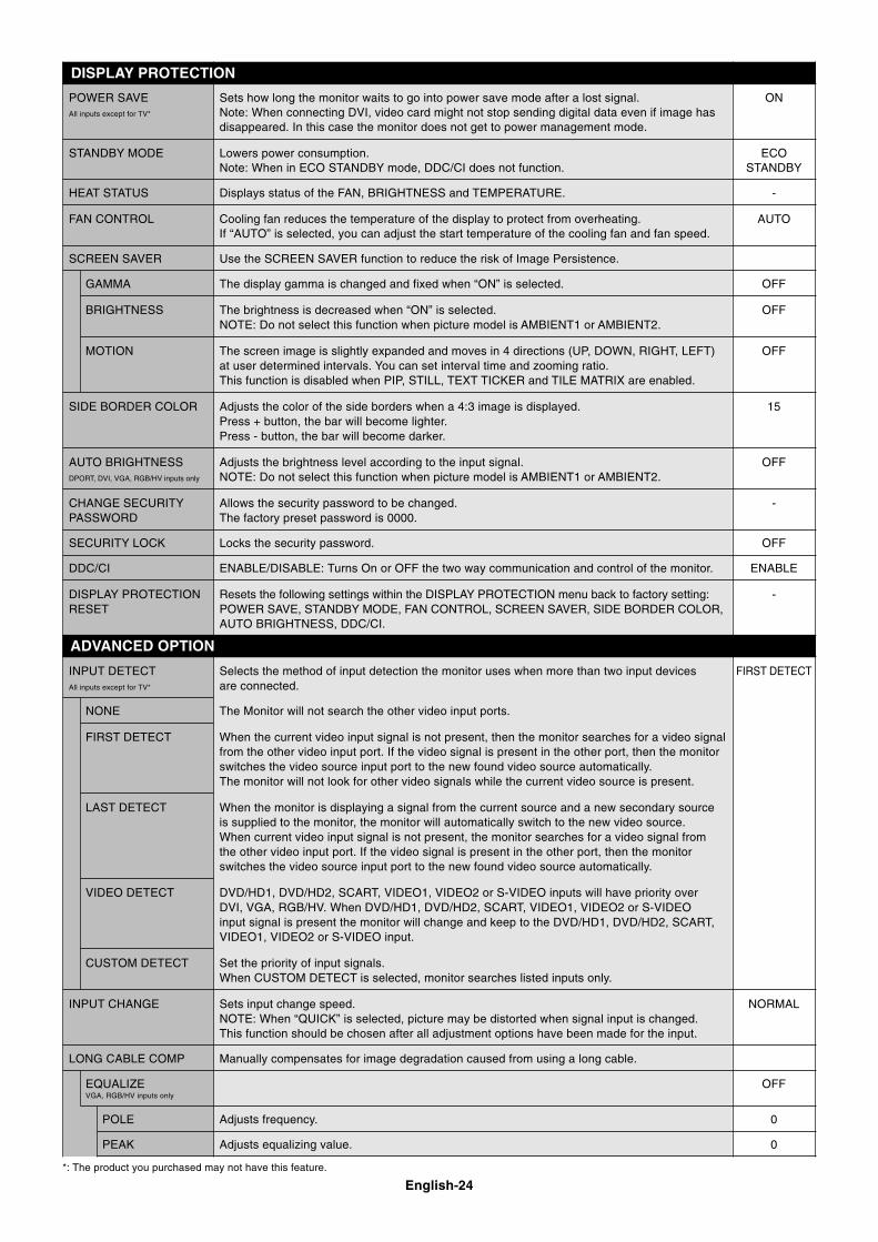
POWER SAVE Sets how long the monitor waits to go into power save mode after a lost signal. ONAll inputs except for TV* Note: When connecting DVI, video card might not stop sending digital data even if image has
disappeared. In this case the monitor does not get to power management mode.
STANDBY MODE Lowers power consumption. ECONote: When in ECO STANDBY mode, DDC/CI does not function. STANDBY
HEAT STATUS Displays status of the FAN, BRIGHTNESS and TEMPERATURE. -
FAN CONTROL Cooling fan reduces the temperature of the display to protect from overheating. AUTOIf “AUTO” is selected, you can adjust the start temperature of the cooling fan and fan speed.
SCREEN SAVER Use the SCREEN SAVER function to reduce the risk of Image Persistence.
GAMMA The display gamma is changed and fixed when “ON” is selected. OFF
BRIGHTNESS The brightness is decreased when “ON” is selected. OFFNOTE: Do not select this function when picture model is AMBIENT1 or AMBIENT2.
MOTION The screen image is slightly expanded and moves in 4 directions (UP, DOWN, RIGHT, LEFT) OFFat user determined intervals. You can set interval time and zooming ratio.This function is disabled when PIP, STILL, TEXT TICKER and TILE MATRIX are enabled.
SIDE BORDER COLOR Adjusts the color of the side borders when a 4:3 image is displayed. 15Press + button, the bar will become lighter.Press - button, the bar will become darker.
AUTO BRIGHTNESS Adjusts the brightness level according to the input signal. OFFDPORT, DVI, VGA, RGB/HV inputs only NOTE: Do not select this function when picture model is AMBIENT1 or AMBIENT2.
CHANGE SECURITY Allows the security password to be changed. -PASSWORD The factory preset password is 0000.
SECURITY LOCK Locks the security password. OFF
DDC/CI ENABLE/DISABLE: Turns On or OFF the two way communication and control of the monitor. ENABLE
DISPLAY PROTECTION Resets the following settings within the DISPLAY PROTECTION menu back to factory setting: -RESET POWER SAVE, STANDBY MODE, FAN CONTROL, SCREEN SAVER, SIDE BORDER COLOR,
AUTO BRIGHTNESS, DDC/CI.
INPUT DETECT Selects the method of input detection the monitor uses when more than two input devices FIRST DETECTAll inputs except for TV* are connected.
NONE The Monitor will not search the other video input ports.
FIRST DETECT When the current video input signal is not present, then the monitor searches for a video signalfrom the other video input port. If the video signal is present in the other port, then the monitorswitches the video source input port to the new found video source automatically.The monitor will not look for other video signals while the current video source is present.
LAST DETECT When the monitor is displaying a signal from the current source and a new secondary sourceis supplied to the monitor, the monitor will automatically switch to the new video source.When current video input signal is not present, the monitor searches for a video signal fromthe other video input port. If the video signal is present in the other port, then the monitorswitches the video source input port to the new found video source automatically.
VIDEO DETECT DVD/HD1, DVD/HD2, SCART, VIDEO1, VIDEO2 or S-VIDEO inputs will have priority overDVI, VGA, RGB/HV. When DVD/HD1, DVD/HD2, SCART, VIDEO1, VIDEO2 or S-VIDEOinput signal is present the monitor will change and keep to the DVD/HD1, DVD/HD2, SCART,VIDEO1, VIDEO2 or S-VIDEO input.
CUSTOM DETECT Set the priority of input signals.When CUSTOM DETECT is selected, monitor searches listed inputs only.
INPUT CHANGE Sets input change speed. NORMALNOTE: When “QUICK” is selected, picture may be distorted when signal input is changed.This function should be chosen after all adjustment options have been made for the input.
LONG CABLE COMP Manually compensates for image degradation caused from using a long cable.
EQUALIZE OFFVGA, RGB/HV inputs only
POLE Adjusts frequency. 0
PEAK Adjusts equalizing value. 0
ADVANCED OPTION
DISPLAY PROTECTION
*: The product you purchased may not have this feature.
English-25
Eng
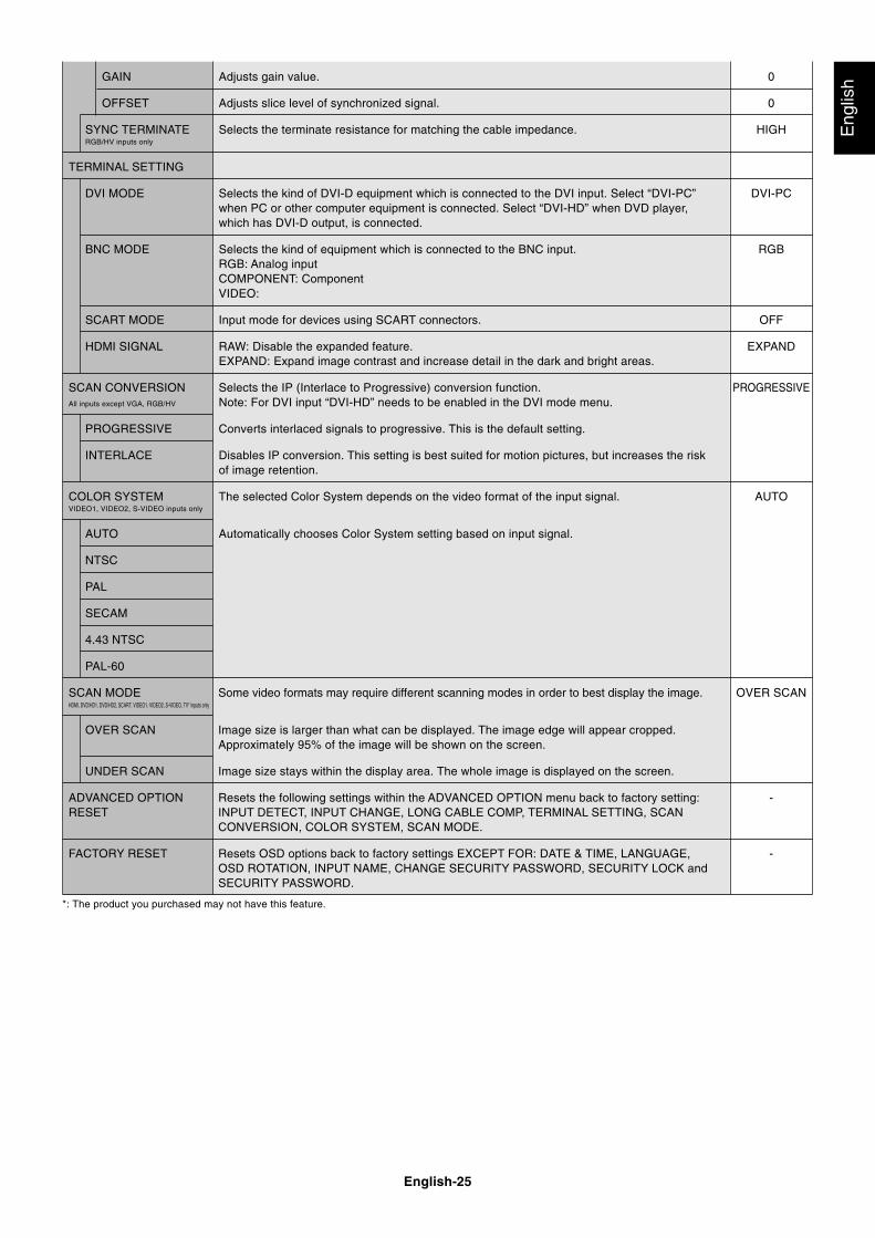
lishGAIN Adjusts gain value. 0
OFFSET Adjusts slice level of synchronized signal. 0
SYNC TERMINATE Selects the terminate resistance for matching the cable impedance. HIGHRGB/HV inputs only
TERMINAL SETTING
DVI MODE Selects the kind of DVI-D equipment which is connected to the DVI input. Select “DVI-PC” DVI-PCwhen PC or other computer equipment is connected. Select “DVI-HD” when DVD player,which has DVI-D output, is connected.
BNC MODE Selects the kind of equipment which is connected to the BNC input. RGBRGB: Analog inputCOMPONENT: ComponentVIDEO:
SCART MODE Input mode for devices using SCART connectors. OFF
HDMI SIGNAL RAW: Disable the expanded feature. EXPANDEXPAND: Expand image contrast and increase detail in the dark and bright areas.
SCAN CONVERSION Selects the IP (Interlace to Progressive) conversion function. PROGRESSIVEAll inputs except VGA, RGB/HV Note: For DVI input “DVI-HD” needs to be enabled in the DVI mode menu.
PROGRESSIVE Converts interlaced signals to progressive. This is the default setting.
INTERLACE Disables IP conversion. This setting is best suited for motion pictures, but increases the riskof image retention.
COLOR SYSTEM The selected Color System depends on the video format of the input signal. AUTOVIDEO1, VIDEO2, S-VIDEO inputs only
AUTO Automatically chooses Color System setting based on input signal.
NTSC
PAL
SECAM
4.43 NTSC
PAL-60
SCAN MODE Some video formats may require different scanning modes in order to best display the image. OVER SCANHDMI, DVD/HD1, DVD/HD2, SCART, VIDEO1, VIDEO2, S-VIDEO, TV* inputs only
OVER SCAN Image size is larger than what can be displayed. The image edge will appear cropped.Approximately 95% of the image will be shown on the screen.
UNDER SCAN Image size stays within the display area. The whole image is displayed on the screen.
ADVANCED OPTION Resets the following settings within the ADVANCED OPTION menu back to factory setting: -RESET INPUT DETECT, INPUT CHANGE, LONG CABLE COMP, TERMINAL SETTING, SCAN
CONVERSION, COLOR SYSTEM, SCAN MODE.
FACTORY RESET Resets OSD options back to factory settings EXCEPT FOR: DATE & TIME, LANGUAGE, -OSD ROTATION, INPUT NAME, CHANGE SECURITY PASSWORD, SECURITY LOCK andSECURITY PASSWORD.
*: The product you purchased may not have this feature.
English-26
NOTE 1: CREATING A SCHEDULEThe schedule function allows the display to be set to power on and off at different times. Up to seven different schedules can beprogrammed.
To program the schedule:
1. Enter the SCHEDULE menu. Highlight SCHEDULE SETTINGS using the up and down buttons. Press the SET or the + button to enter theSettings menu. Highlight the desired schedule number and press set. The box next to the number will turn yellow. The schedule can nowbe programmed.
2. Use the down button to highlight the hours setting in the ON time slot. Use the + and - buttons to set the hour. Use the up and downbuttons to highlight the minutes setting. Use the + and - buttons to set the minutes. Set the OFF time in the same manner.
3. Use the up and down arrows to highlight INPUT. Use the + and - buttons to choose the input source. Use the up and down arrows tohighlight PIC. MODE. Use the + and - buttons to choose the picture mode.
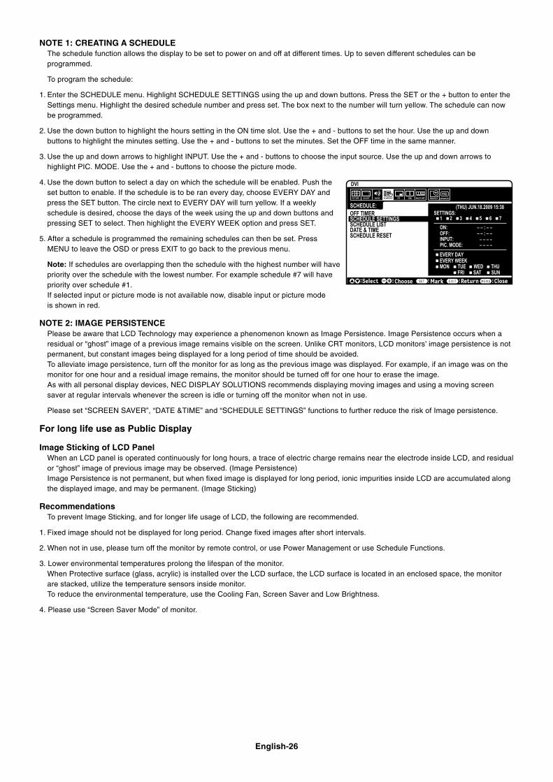
4. Use the down button to select a day on which the schedule will be enabled. Push theset button to enable. If the schedule is to be ran every day, choose EVERY DAY andpress the SET button. The circle next to EVERY DAY will turn yellow. If a weeklyschedule is desired, choose the days of the week using the up and down buttons andpressing SET to select. Then highlight the EVERY WEEK option and press SET.
5. After a schedule is programmed the remaining schedules can then be set. PressMENU to leave the OSD or press EXIT to go back to the previous menu.
Note: If schedules are overlapping then the schedule with the highest number will havepriority over the schedule with the lowest number. For example schedule #7 will havepriority over schedule #1.If selected input or picture mode is not available now, disable input or picture modeis shown in red.
NOTE 2: IMAGE PERSISTENCEPlease be aware that LCD Technology may experience a phenomenon known as Image Persistence. Image Persistence occurs when aresidual or “ghost” image of a previous image remains visible on the screen. Unlike CRT monitors, LCD monitors’ image persistence is notpermanent, but constant images being displayed for a long period of time should be avoided.To alleviate image persistence, turn off the monitor for as long as the previous image was displayed. For example, if an image was on themonitor for one hour and a residual image remains, the monitor should be turned off for one hour to erase the image.As with all personal display devices, NEC DISPLAY SOLUTIONS recommends displaying moving images and using a moving screensaver at regular intervals whenever the screen is idle or turning off the monitor when not in use.
Please set “SCREEN SAVER”, “DATE &TIME” and “SCHEDULE SETTINGS” functions to further reduce the risk of Image persistence.
For long life use as Public Display
Image Sticking of LCD PanelWhen an LCD panel is operated continuously for long hours, a trace of electric charge remains near the electrode inside LCD, and residualor “ghost” image of previous image may be observed. (Image Persistence)Image Persistence is not permanent, but when fixed image is displayed for long period, ionic impurities inside LCD are accumulated alongthe displayed image, and may be permanent. (Image Sticking)
RecommendationsTo prevent Image Sticking, and for longer life usage of LCD, the following are recommended.
1. Fixed image should not be displayed for long period. Change fixed images after short intervals.
2. When not in use, please turn off the monitor by remote control, or use Power Management or use Schedule Functions.
3. Lower environmental temperatures prolong the lifespan of the monitor.When Protective surface (glass, acrylic) is installed over the LCD surface, the LCD surface is located in an enclosed space, the monitorare stacked, utilize the temperature sensors inside monitor.To reduce the environmental temperature, use the Cooling Fan, Screen Saver and Low Brightness.
4. Please use “Screen Saver Mode” of monitor.
SCHEDULE:
ON: – – : – –OFF: – – : – –
– – – –INPUT:PIC. MODE: – – – –
DVI
(THU) JUN.18.2009 15:38 SETTINGS:OFF TIMER
SCHEDULE SETTINGSSCHEDULE LISTDATE & TIMESCHEDULE RESET RESET
� MON TUE WED THUSAT SUNFRI
1 2 3 4 5 6 7
Choose Mark Return Close
EVERY DAYEVERY WEEK
English-27
Eng
lish
REMOTE CONTROL ID FUNCTION
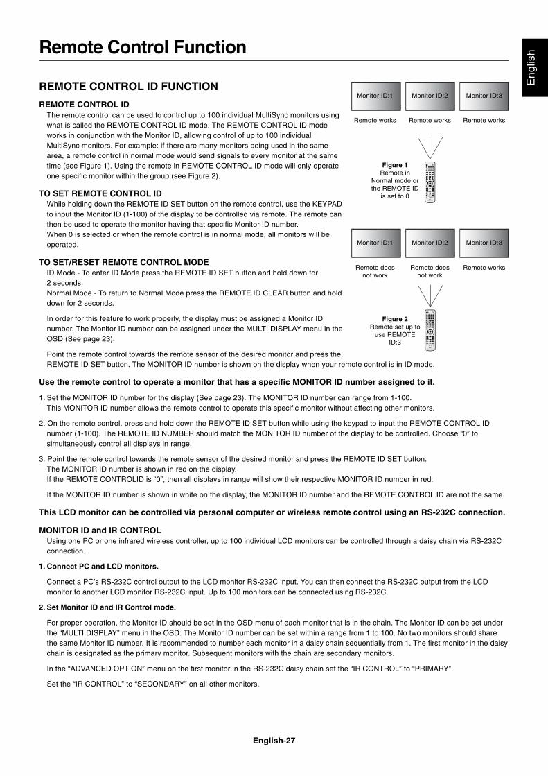
REMOTE CONTROL IDThe remote control can be used to control up to 100 individual MultiSync monitors usingwhat is called the REMOTE CONTROL ID mode. The REMOTE CONTROL ID modeworks in conjunction with the Monitor ID, allowing control of up to 100 individualMultiSync monitors. For example: if there are many monitors being used in the samearea, a remote control in normal mode would send signals to every monitor at the sametime (see Figure 1). Using the remote in REMOTE CONTROL ID mode will only operateone specific monitor within the group (see Figure 2).
TO SET REMOTE CONTROL IDWhile holding down the REMOTE ID SET button on the remote control, use the KEYPADto input the Monitor ID (1-100) of the display to be controlled via remote. The remote canthen be used to operate the monitor having that specific Monitor ID number.When 0 is selected or when the remote control is in normal mode, all monitors will beoperated.
TO SET/RESET REMOTE CONTROL MODEID Mode - To enter ID Mode press the REMOTE ID SET button and hold down for2 seconds.Normal Mode - To return to Normal Mode press the REMOTE ID CLEAR button and holddown for 2 seconds.
In order for this feature to work properly, the display must be assigned a Monitor IDnumber. The Monitor ID number can be assigned under the MULTI DISPLAY menu in theOSD (See page 23).
Point the remote control towards the remote sensor of the desired monitor and press theREMOTE ID SET button. The MONITOR ID number is shown on the display when your remote control is in ID mode.
Use the remote control to operate a monitor that has a specific MONITOR ID number assigned to it.
1. Set the MONITOR ID number for the display (See page 23). The MONITOR ID number can range from 1-100.This MONITOR ID number allows the remote control to operate this specific monitor without affecting other monitors.
2. On the remote control, press and hold down the REMOTE ID SET button while using the keypad to input the REMOTE CONTROL IDnumber (1-100). The REMOTE ID NUMBER should match the MONITOR ID number of the display to be controlled. Choose “0” tosimultaneously control all displays in range.
3. Point the remote control towards the remote sensor of the desired monitor and press the REMOTE ID SET button.The MONITOR ID number is shown in red on the display.If the REMOTE CONTROLID is “0”, then all displays in range will show their respective MONITOR ID number in red.
If the MONITOR ID number is shown in white on the display, the MONITOR ID number and the REMOTE CONTROL ID are not the same.
This LCD monitor can be controlled via personal computer or wireless remote control using an RS-232C connection.
MONITOR ID and IR CONTROLUsing one PC or one infrared wireless controller, up to 100 individual LCD monitors can be controlled through a daisy chain via RS-232Cconnection.
1. Connect PC and LCD monitors.
Connect a PC’s RS-232C control output to the LCD monitor RS-232C input. You can then connect the RS-232C output from the LCDmonitor to another LCD monitor RS-232C input. Up to 100 monitors can be connected using RS-232C.
2. Set Monitor ID and IR Control mode.
For proper operation, the Monitor ID should be set in the OSD menu of each monitor that is in the chain. The Monitor ID can be set underthe “MULTI DISPLAY” menu in the OSD. The Monitor ID number can be set within a range from 1 to 100. No two monitors should sharethe same Monitor ID number. It is recommended to number each monitor in a daisy chain sequentially from 1. The first monitor in the daisychain is designated as the primary monitor. Subsequent monitors with the chain are secondary monitors.
In the “ADVANCED OPTION” menu on the first monitor in the RS-232C daisy chain set the “IR CONTROL” to “PRIMARY”.
Set the “IR CONTROL” to “SECONDARY” on all other monitors.
Remote Control Function
Monitor ID:1 Monitor ID:2 Monitor ID:3
Monitor ID:1 Monitor ID:2 Monitor ID:3
Remote doesnot work
Remote doesnot work
Remote works
Remote works Remote works Remote works
Figure 1Remote in
Normal mode orthe REMOTE ID
is set to 0
Figure 2Remote set up to
use REMOTEID:3
English-28
3. Press the “DISPLAY” button on the remote control while aiming at the “PRIMARY” monitor. The Information OSD will be shown attop left side of the screen.
Monitor ID: Displays the ID number of the current monitor within the daisy chain.
Target ID: Displays the ID number of the monitor that to be controlled via daisy chain from the current monitor.
Press the “+” or “-” buttons to change the “Target ID” to show the ID number of the monitor to be controlled. To control the entire daisychained monitors simultaneously, select “ALL” as the “Target ID.”
4. Use the wireless remote controller to control the “SECONDARY” monitor while aiming at the “PRIMARY” monitor.
The “MENU OSD” will appear on the selected target monitor.
NOTE: If the “ID No.” mode select OSD is showing, press the “DISPLAY” button on the remote control while pointing at the “PRIMARY”monitor to clear this OSD.
HINT: If you lost control due to the incorrect setting of “IR CONTROL”, pressing the “DISPLAY” button on the remote control for 5 ormore seconds will reset the “IR CONTROL” menu to “NORMAL” function.
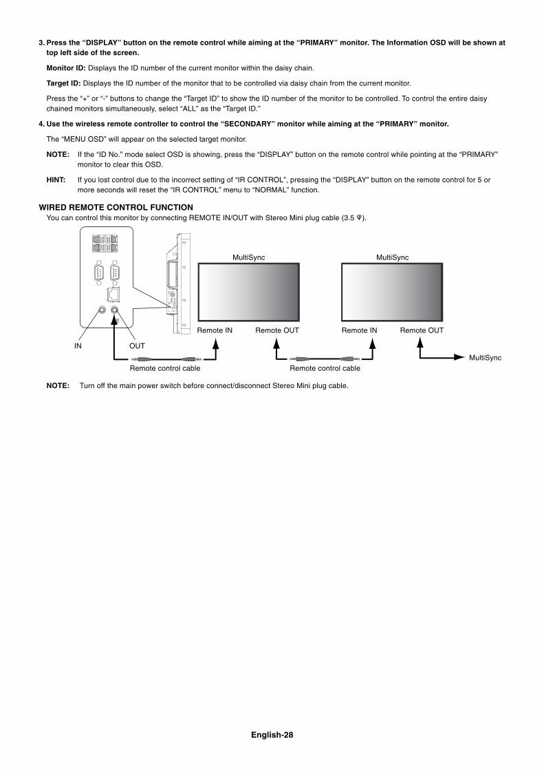
WIRED REMOTE CONTROL FUNCTIONYou can control this monitor by connecting REMOTE IN/OUT with Stereo Mini plug cable (3.5 ).
Remote control cable
Remote IN
IN OUT
MultiSync MultiSync
MultiSyncRemote control cable
Remote OUT Remote IN Remote OUT
NOTE: Turn off the main power switch before connect/disconnect Stereo Mini plug cable.
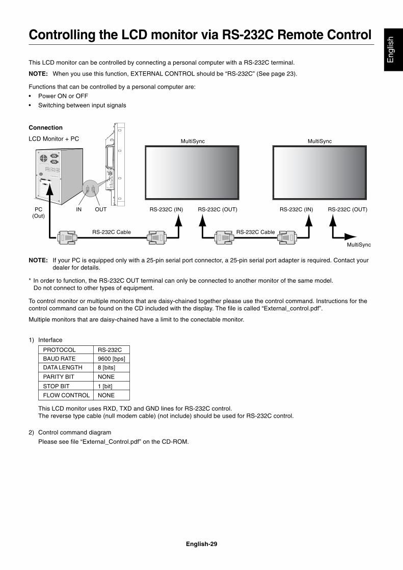
English-29
Eng
lish
This LCD monitor can be controlled by connecting a personal computer with a RS-232C terminal.
NOTE: When you use this function, EXTERNAL CONTROL should be “RS-232C” (See page 23).
Functions that can be controlled by a personal computer are:
• Power ON or OFF
• Switching between input signals
Connection
LCD Monitor + PC
RS-232C Cable
PC(Out)
RS-232C Cable
RS-232C (OUT)
MultiSync
RS-232C (IN)RS-232C (OUT)RS-232C (IN)IN OUT
MultiSync
Controlling the LCD monitor via RS-232C Remote Control
MultiSync
NOTE: If your PC is equipped only with a 25-pin serial port connector, a 25-pin serial port adapter is required. Contact yourdealer for details.
* In order to function, the RS-232C OUT terminal can only be connected to another monitor of the same model.Do not connect to other types of equipment.
To control monitor or multiple monitors that are daisy-chained together please use the control command. Instructions for thecontrol command can be found on the CD included with the display. The file is called “External_control.pdf”.
Multiple monitors that are daisy-chained have a limit to the conectable monitor.
1) Interface
This LCD monitor uses RXD, TXD and GND lines for RS-232C control.The reverse type cable (null modem cable) (not include) should be used for RS-232C control.
2) Control command diagram
Please see file “External_Control.pdf” on the CD-ROM.
PROTOCOL RS-232C
BAUD RATE 9600 [bps]
DATA LENGTH 8 [bits]
PARITY BIT NONE
STOP BIT 1 [bit]
FLOW CONTROL NONE
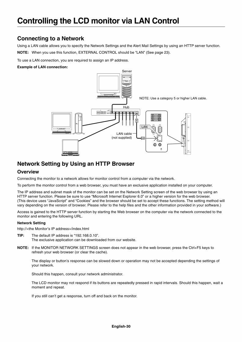
English-30
Connecting to a NetworkUsing a LAN cable allows you to specify the Network Settings and the Alert Mail Settings by using an HTTP server function.
NOTE: When you use this function, EXTERNAL CONTROL should be “LAN” (See page 23).
To use a LAN connection, you are required to assign an IP address.
Example of LAN connection:
Controlling the LCD monitor via LAN Control
Server
Hub
NOTE: Use a category 5 or higher LAN cable.
LAN cable(not supplied)
Network Setting by Using an HTTP BrowserOverviewConnecting the monitor to a network allows for monitor control from a computer via the network.
To perform the monitor control from a web browser, you must have an exclusive application installed on your computer.
The IP address and subnet mask of the monitor can be set on the Network Setting screen of the web browser by using anHTTP server function. Please be sure to use “Microsoft Internet Explorer 6.0” or a higher version for the web browser.(This device uses “JavaScript” and “Cookies” and the browser should be set to accept these functions. The setting method willvary depending on the version of browser. Please refer to the help files and the other information provided in your software.)
Access is gained to the HTTP server function by starting the Web browser on the computer via the network connected to themonitor and entering the following URL.
Network Setting
http://<the Monitor’s IP address>/index.html
TIP: The default IP address is “192.168.0.10”.The exclusive application can be downloaded from our website.
NOTE: If the MONITOR NETWORK SETTINGS screen does not appear in the web browser, press the Ctrl+F5 keys torefresh your web browser (or clear the cache).
The display or button’s response can be slowed down or operation may not be accepted depending the settings ofyour network.
Should this happen, consult your network administrator.
The LCD monitor may not respond if its buttons are repeatedly pressed in rapid intervals. Should this happen, wait amoment and repeat.
If you still can’t get a response, turn off and back on the monitor.
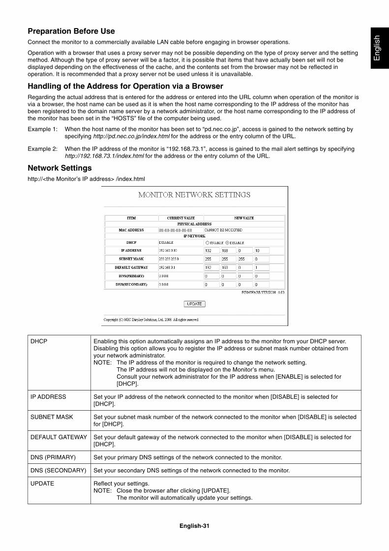
English-31
Eng
lish
Preparation Before UseConnect the monitor to a commercially available LAN cable before engaging in browser operations.
Operation with a browser that uses a proxy server may not be possible depending on the type of proxy server and the settingmethod. Although the type of proxy server will be a factor, it is possible that items that have actually been set will not bedisplayed depending on the effectiveness of the cache, and the contents set from the browser may not be reflected inoperation. It is recommended that a proxy server not be used unless it is unavailable.
Handling of the Address for Operation via a BrowserRegarding the actual address that is entered for the address or entered into the URL column when operation of the monitor isvia a browser, the host name can be used as it is when the host name corresponding to the IP address of the monitor hasbeen registered to the domain name server by a network administrator, or the host name corresponding to the IP address ofthe monitor has been set in the “HOSTS” file of the computer being used.
Example 1: When the host name of the monitor has been set to “pd.nec.co.jp”, access is gained to the network setting byspecifying http://pd.nec.co.jp/index.html for the address or the entry column of the URL.
Example 2: When the IP address of the monitor is “192.168.73.1”, access is gained to the mail alert settings by specifyinghttp://192.168.73.1/index.html for the address or the entry column of the URL.
Network Settingshttp://<the Monitor’s IP address> /index.html
Enabling this option automatically assigns an IP address to the monitor from your DHCP server.Disabling this option allows you to register the IP address or subnet mask number obtained fromyour network administrator.NOTE: The IP address of the monitor is required to change the network setting.
The IP address will not be displayed on the Monitor’s menu.Consult your network administrator for the IP address when [ENABLE] is selected for[DHCP].
Set your IP address of the network connected to the monitor when [DISABLE] is selected for[DHCP].
Set your subnet mask number of the network connected to the monitor when [DISABLE] is selectedfor [DHCP].
Set your default gateway of the network connected to the monitor when [DISABLE] is selected for[DHCP].
Set your primary DNS settings of the network connected to the monitor.
Set your secondary DNS settings of the network connected to the monitor.
Reflect your settings.NOTE: Close the browser after clicking [UPDATE].
The monitor will automatically update your settings.
DHCP
IP ADDRESS
SUBNET MASK
DEFAULT GATEWAY
DNS (PRIMARY)
DNS (SECONDARY)
UPDATE
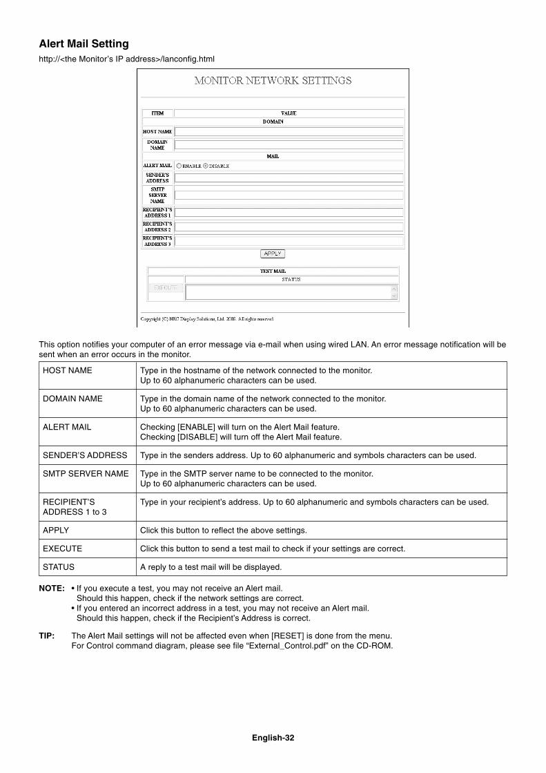
English-32
Alert Mail Settinghttp://<the Monitor’s IP address>/lanconfig.html
Type in the hostname of the network connected to the monitor.Up to 60 alphanumeric characters can be used.
Type in the domain name of the network connected to the monitor.Up to 60 alphanumeric characters can be used.
Checking [ENABLE] will turn on the Alert Mail feature.Checking [DISABLE] will turn off the Alert Mail feature.
Type in the senders address. Up to 60 alphanumeric and symbols characters can be used.
Type in the SMTP server name to be connected to the monitor.Up to 60 alphanumeric characters can be used.
Type in your recipient’s address. Up to 60 alphanumeric and symbols characters can be used.
Click this button to reflect the above settings.
Click this button to send a test mail to check if your settings are correct.
A reply to a test mail will be displayed.
HOST NAME
DOMAIN NAME
ALERT MAIL
SENDER’S ADDRESS
SMTP SERVER NAME
RECIPIENT’SADDRESS 1 to 3
APPLY
EXECUTE
STATUS
This option notifies your computer of an error message via e-mail when using wired LAN. An error message notification will besent when an error occurs in the monitor.
NOTE: • If you execute a test, you may not receive an Alert mail.Should this happen, check if the network settings are correct.
• If you entered an incorrect address in a test, you may not receive an Alert mail.Should this happen, check if the Recipient’s Address is correct.
TIP: The Alert Mail settings will not be affected even when [RESET] is done from the menu.For Control command diagram, please see file “External_Control.pdf” on the CD-ROM.

English-33
Eng
lish
Reduced Footprint: Provides the ideal solution for environments requiring superior image quality but with size and weightlimitations.
Color Control Systems: Allows you to adjust the colors on your screen and customize the color accuracy of your monitor toa variety of standards.
OmniColor: Combines Six-axis color control and the sRGB standard. Six-axis color control permits color adjustments via sixaxes (R, G, B, C, M and Y) rather than through the three axes (R, G and B) previously available. The sRGB standard providesthe monitor with a uniform color profile. This assures that the colors displayed on the monitor are exactly the same as on thecolor printout (with sRGB supporting operating system and sRGB printer). This allows you to adjust the colors on your screenand customise the color accuracy of your monitor to a variety of standards.
sRGB Color Control: A new optimized color management standard which allows for color matching on computer displaysand other peripherals. The sRGB standard, which is based on a calibrated color space, allows for optimal color representationand backward compatibility with other common color standards.
OSD (On-Screen-Display) Controls: Allow you to quickly and easily adjust all elements of your screen image via simple touse on-screen menus.
Plug and Play: The Microsoft® solution with the Windows® operating system facilitates setup and installation by allowing themonitor to send its capabilities (such as screen size and resolutions supported) directly to your computer, automaticallyoptimizing display performance.
IPM (Intelligent Power Manager) System: Provides innovative power-saving methods that allow the monitor to shift to alower power consumption level when on but not in use, saving two-thirds of your monitor energy costs, reducing emissionsand lowering the air conditioning costs of the workplace.
FullScan Capability: Allows you to use the entire screen area in most resolutions, significantly expanding image size.
VESA Standard (FDMIv1) Mounting Interface: Allows users to connect their LCD monitor to any VESA standard (FDMIv1)third party mounting arm or bracket. Allows for the monitor to be mounted on a wall or an arm using any third party compliantdevice. NEC recommends using mounting interface that comply with TÜV-GS and/or UL1678 standard in North America.
DVI-D: The digital-only subset of DVI ratified by the Digital Display Working Group (DDWG) for digital connections betweencomputers and displays. As a digital-only connector, analog support is not provided for a DVI-D connector. As a DVI-baseddigital only connection, only a simple adapter is necessary for compatibility between DVI-D and other DVI-based digitalconnectors such as DFP and P&D. The DVI interface of this display supports HDCP.
TILE MATRIX, TILE COMP: Shows one image over multiple screens with accuracy while compensating for bezel width.
ZOOM: Expands image size for horizontal and vertical direction.
RS-232C daisy chain: You can control the multiple monitors by controller or wireless remote controller.
Self-diagnosis: If an internal error should occur, a failure state will be indicated.
Long cable capability: Automatic long cable compensation prevents image quality degradation (dull signals) caused by longcable lengths.
Features
English-34
No picture• The signal cable should be completely connected to the
display card/computer.
• The display card should be completely seated in its slot.
• Front Power Switch and computer power switch shouldbe in the ON position.
• Check to make sure that a supported mode has beenselected on the display card or system being used.(Please consult display card or system manual tochange graphics mode.)
• Check the monitor and your display card with respect tocompatibility and recommended settings.
• Check the signal cable connector for bent or pushed-inpins.
Power Button does not respond• Unplug the power cord of the monitor from the AC outlet
to turn off and reset the monitor.
Image persistence• Please be aware that LCD Technology may experience a
phenomenon known as Image Persistence. ImagePersistence occurs when a residual or “ghost” image of aprevious image remains visible on the screen. UnlikeCRT monitors, LCD monitors’ image persistence is notpermanent, but constant images being displayed for along period of time should be avoided. To alleviate imagepersistence, turn off the monitor for as long as theprevious image was displayed. For example, if an imagewas on the monitor for one hour and a residual imageremains, the monitor should be turned off for one hour toerase the image.
NOTE: As with all personal display devices, NEC DISPLAYSOLUTIONS recommends displaying movingimages and using a moving screen saver at regularintervals whenever the screen is idle or turning offthe monitor when not in use.
Image is unstable, unfocused or swimming is apparent• Signal cable should be completely attached to the
computer.
• Use the OSD Image Adjust controls to focus and adjustdisplay by increasing or decreasing the fine adjustment.When the display mode is changed, the OSD ImageAdjust settings may need to be re-adjusted.
• Check the monitor and your display card with respect tocompatibility and recommended signal timings.
• If your text is garbled, change the video mode to non-interlace and use 60Hz refresh rate.
Image of component signal is greenish• Check to see if the DVD/HD input connector is selected.
LED on monitor is not lit(no green or red color can be seen)• Power Switch should be in the ON position and power
cord should be connected.
• Make certain the computer is not in a power-savingmode (touch the keyboard or mouse).
• Check to see that the power indicator option in the OSDis set to ON.
RED LED on monitor is blinking• A certain failure might have occurred, please contact
your nearest authorized NEC DISPLAY SOLUTIONSservice facility.
• If the monitor is powered off by the inside temperaturebeing higher than the normal operating temperature, aRED LED will blink six times. Power on the display againafter confirming the inside temperature has beenreduced to normal operation temperature.
Display image is not sized properly• Use the OSD Image Adjust controls to increase or
decrease the coarse adjustment.
• Check to make sure that a supported mode has beenselected on the display card or system being used.(Please consult display card or system manual tochange graphics mode.)
Selected resolution is not displayed properly• Use OSD Display Mode to enter Information menu and
confirm that the appropriate resolution has beenselected. If not, select corresponding option.
No Sound• Check to see if audio cable is properly connected.
• Check to see if mute is activated.
• Check to see if volume is set at minimum.
• Check to see if computer supports an audio signalthrough DisplayPort.If unsure, contact the computer manufacturer.
Remote Control is not available• Check the Remote Control’s batteries status.
• Check if batteries are inserted correctly.
• Check if the Remote Control is pointing at the monitor’sremote sensor.
• Check the Remote Control Mode status.
• The remote control system may not function when directsunlight or strong illumination strikes the remote controlsensor of the LCD monitor, or when there is an object inthe path.
“SCHEDULE”/“OFF TIMER” function is not workingproperly• The “SCHEDULE” function will be disabled when the
“OFF TIMER” is set.
• If the “OFF TIMER” function is enabled and the power tothe LCD monitor is turned off when the power supply isinterrupted unexpectedly, then the “OFF TIMER” will bereset.
Snowy Picture, Poor Sound in TV• Check antenna/cable connection. Use new cable if
necessary.
Interference in TV• Check components for shielding, move away from
monitor if necessary.
RS-232C or LAN control is not available• Check RS-232C or LAN cable connection.
• Check “CONTROL” setting in “EXTERNAL CONTROL”.
Either light vertical or horizontal stripes may appear, depending on the specific display pattern. This is no product fault ordegradation.
Troubleshooting

English-35
Eng
lishSpecifications - P401
Product Specifications
LCD Module 40" /101.6 cm diagonalPixel Pitch: 0.461 mmResolution: 1920 x 1080
Color: Over 16 million colors (depending on video card used)Brightness: 650 cd/m2 (Max.), 500 cd/m2 (Typ.) @25°C
Contrast Ratio: 3000:1Viewing Angle: 89° (typ) @ CR>10
Design View Distance: 1100 mm
Frequency Horizontal: 15.625/15.734 kHz, 31.5 kHz - 91.1 kHz (Analog Input)31.5 kHz - 91.1 kHz (Digital Input)
Vertical: 50.0 - 85.0 Hz
Pixel Clock 25.2 MHz - 162.0 MHz
Viewable Size 885.6 x 498.2 mm
Input Signal
DVI DVI-D 24pin Digital RGB DVI (HDCP)VGA60, SVGA60, XGA60, WXGA60, SXGA60, UXGA60*1, 1920X1080 (60Hz)
DisplayPort DisplayPort Connector Digital RGB DisplayPort Complies with Standard V1.1a, applicable to HDCP1.3VGA60, SVGA60, XGA60, WXGA60, SXGA60, UXGA60*1, 1920x1080 (60 Hz)
VGA 15pin Mini D-sub Analog RGB 0.7 Vp-p/75 ohmVGA60, SVGA60, XGA60, WXGA60, SXGA60, UXGA60*1, 1920X1080 (60Hz)
Sync Separate: TTL level (Pos./Neg.)Composite sync on Green Video: 0.3 Vp-p Neg.
RGB/HV BNC (R,G,B,H,V) Analog RGB 0.7 Vp-p/75 ohmVGA60, SVGA60, XGA60, WXGA60, SXGA60, UXGA60*1, 1920X1080 (60Hz)
Sync Separate: TTL level (Pos./Neg.)Composite sync on Green Video: 0.3 Vp-p Neg.
HDMI HDMI Connector Digital RGB HDMI1080p, 1080i, 720p@50Hz/60Hz, 576p@50Hz, 480p@60Hz
DVD/HD1 RCA (Y, Cb/Pb, Cr/Pr) Component Y: 1.0 Vp-p/75ohm, Cb/Cr (Pb/Pr): 0.7 Vp-p/75 ohmDVD/HD2 BNC HDTV/DVD: 1080p, 1080i, 720p@50Hz/60Hz, 576p@50Hz, 480p@60Hz, 576i@50Hz, 480i@60Hz
VIDEO1 BNC/RCA Composite 1.0 Vp-p/75 ohmVIDEO2 BNC NTSC/PAL/SECAM/4.43NTSC/PAL60
S-VIDEO Mini DIN 4 pin S-VIDEO Y: 1.0 Vp-p/75 ohm C: 0.286 Vp-p/75 ohm (NTSC), 0.3 Vp-p/75 ohm (PAL/SECAM)NTSC/PAL/SECAM/4.43NTSC/PAL60
Output Signal
RGB/HV BNC (R,G,B,H,V) Analog RGB 0.7 Vp-p with 75 ohm terminatedSeparate HV sync: TTL level (Posi / Nega)
DVD/HD2 BNC Component Y: 1.0 Vp-p/75ohm, Cb/Cr (Pb/Pr): 0.7 Vp-p/75 ohm
VIDEO1/VIDEO2 BNC Composite 1.0 Vp-p with 75 ohm terminated
AUDIO
AUDIO RCA (L/R) X2 Analog Audio Stereo L/R 0.5 VrmsInput STEREO Mini Jack
HDMI Connector Digital Audio PCM 32, 44.1, 48 KHz (16/20/24bit)
DisplayPort Connector Digital Audio PCM 32, 44.1, 48 KHz (16/20/24bit)
AUDIO RCA (L/R) Analog Audio Stereo L/R 0.5 VrmsOutput
Speaker Output External Speaker Jack 15 W + 15 W (8 ohm)
Control RS-232C In: 9 Pin D-subRS-232C Out: 9 Pin D-sub (with daisy chain)
LAN: RJ-45 10/100 BASE-TRemote IN: Stereo Mini jack 3.5
Remote OUT: Stereo Mini jack 3.5
Power Supply 3.5 - 1.45 A @ 100-240VAC, 50/60Hz
Operational Environment Temperature: 5 - 40°C / 41 - 104°F (Default brightness), 5 - 20°C / 41 - 68°F (Max brightness)Humidity: 20 - 80% (without condensation)
Altitude: 0 - 3000 m (Brightness may decrease with altitude)
Storage Environment Temperature: -20 - 60°C / -4 - 140°FHumidity: 10 - 90% (without condensation) / 90% - 3.5% x (Temp - 40°C) regarding over 40°C
Dimension 919.7 (W) x 532.2 (H) x 140.0 (D) mm / 36.2 (W) x 21.0 (H) x 5.5 (D) inches
Weight 24.0 Kg (52.9 lbs)
VESA compatible arm mounting interface 300 mm x 300 mm (M6, 4 Holes)
Power Management VESA DPM
Plug & Play VESA DDC2B, DDC/CI, DisplayPort
Accessories Setup manual, Power Cord, Video Signal cable, Remote Control, AA Battery x 2, Clamp x 3,Screw x 9, CD-ROM, Thumbscrew for optional stand x 2, Cable cover
NOTE: Technical specifications are subject to change without notice. *1: Compressed image
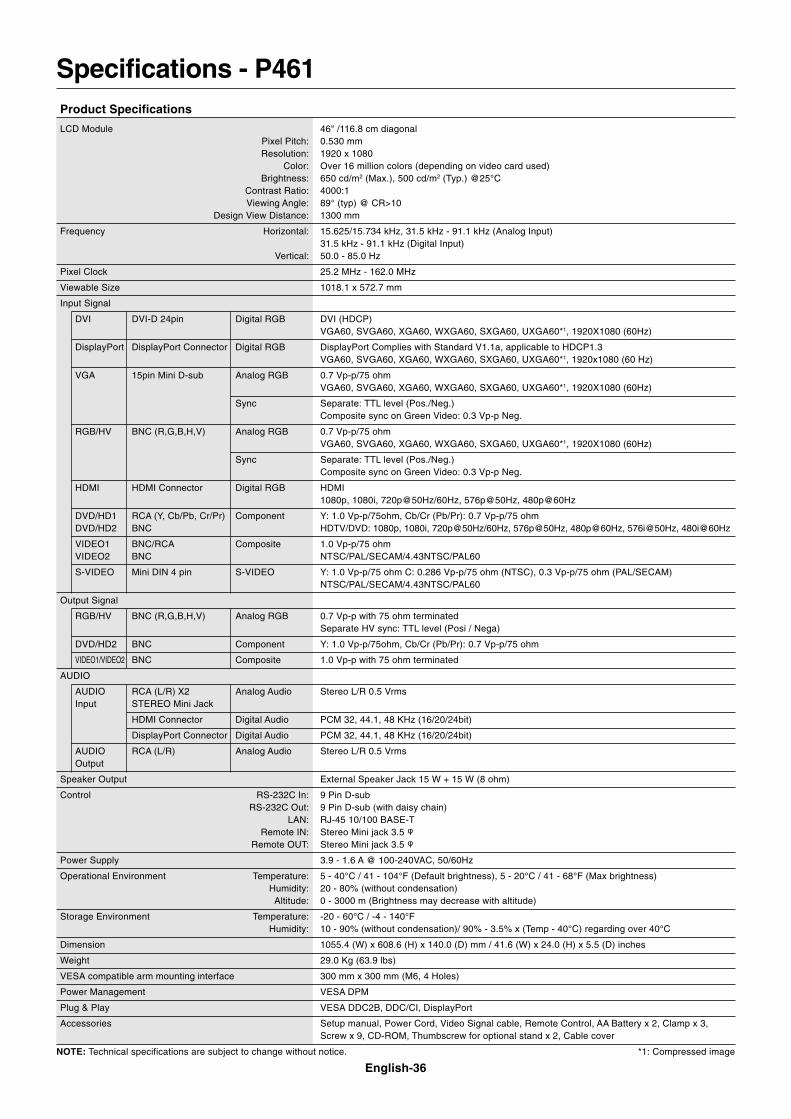
English-36
Specifications - P461Product Specifications
LCD Module 46" /116.8 cm diagonalPixel Pitch: 0.530 mmResolution: 1920 x 1080
Color: Over 16 million colors (depending on video card used)Brightness: 650 cd/m2 (Max.), 500 cd/m2 (Typ.) @25°C
Contrast Ratio: 4000:1Viewing Angle: 89° (typ) @ CR>10
Design View Distance: 1300 mm
Frequency Horizontal: 15.625/15.734 kHz, 31.5 kHz - 91.1 kHz (Analog Input)31.5 kHz - 91.1 kHz (Digital Input)
Vertical: 50.0 - 85.0 Hz
Pixel Clock 25.2 MHz - 162.0 MHz
Viewable Size 1018.1 x 572.7 mm
Input Signal
DVI DVI-D 24pin Digital RGB DVI (HDCP)VGA60, SVGA60, XGA60, WXGA60, SXGA60, UXGA60*1, 1920X1080 (60Hz)
DisplayPort DisplayPort Connector Digital RGB DisplayPort Complies with Standard V1.1a, applicable to HDCP1.3VGA60, SVGA60, XGA60, WXGA60, SXGA60, UXGA60*1, 1920x1080 (60 Hz)
VGA 15pin Mini D-sub Analog RGB 0.7 Vp-p/75 ohmVGA60, SVGA60, XGA60, WXGA60, SXGA60, UXGA60*1, 1920X1080 (60Hz)
Sync Separate: TTL level (Pos./Neg.)Composite sync on Green Video: 0.3 Vp-p Neg.
RGB/HV BNC (R,G,B,H,V) Analog RGB 0.7 Vp-p/75 ohmVGA60, SVGA60, XGA60, WXGA60, SXGA60, UXGA60*1, 1920X1080 (60Hz)
Sync Separate: TTL level (Pos./Neg.)Composite sync on Green Video: 0.3 Vp-p Neg.
HDMI HDMI Connector Digital RGB HDMI1080p, 1080i, 720p@50Hz/60Hz, 576p@50Hz, 480p@60Hz
DVD/HD1 RCA (Y, Cb/Pb, Cr/Pr) Component Y: 1.0 Vp-p/75ohm, Cb/Cr (Pb/Pr): 0.7 Vp-p/75 ohmDVD/HD2 BNC HDTV/DVD: 1080p, 1080i, 720p@50Hz/60Hz, 576p@50Hz, 480p@60Hz, 576i@50Hz, 480i@60Hz
VIDEO1 BNC/RCA Composite 1.0 Vp-p/75 ohmVIDEO2 BNC NTSC/PAL/SECAM/4.43NTSC/PAL60
S-VIDEO Mini DIN 4 pin S-VIDEO Y: 1.0 Vp-p/75 ohm C: 0.286 Vp-p/75 ohm (NTSC), 0.3 Vp-p/75 ohm (PAL/SECAM)NTSC/PAL/SECAM/4.43NTSC/PAL60
Output Signal
RGB/HV BNC (R,G,B,H,V) Analog RGB 0.7 Vp-p with 75 ohm terminatedSeparate HV sync: TTL level (Posi / Nega)
DVD/HD2 BNC Component Y: 1.0 Vp-p/75ohm, Cb/Cr (Pb/Pr): 0.7 Vp-p/75 ohm
VIDEO1/VIDEO2 BNC Composite 1.0 Vp-p with 75 ohm terminated
AUDIO
AUDIO RCA (L/R) X2 Analog Audio Stereo L/R 0.5 VrmsInput STEREO Mini Jack
HDMI Connector Digital Audio PCM 32, 44.1, 48 KHz (16/20/24bit)
DisplayPort Connector Digital Audio PCM 32, 44.1, 48 KHz (16/20/24bit)
AUDIO RCA (L/R) Analog Audio Stereo L/R 0.5 VrmsOutput
Speaker Output External Speaker Jack 15 W + 15 W (8 ohm)
Control RS-232C In: 9 Pin D-subRS-232C Out: 9 Pin D-sub (with daisy chain)
LAN: RJ-45 10/100 BASE-TRemote IN: Stereo Mini jack 3.5
Remote OUT: Stereo Mini jack 3.5
Power Supply 3.9 - 1.6 A @ 100-240VAC, 50/60Hz
Operational Environment Temperature: 5 - 40°C / 41 - 104°F (Default brightness), 5 - 20°C / 41 - 68°F (Max brightness)Humidity: 20 - 80% (without condensation)
Altitude: 0 - 3000 m (Brightness may decrease with altitude)
Storage Environment Temperature: -20 - 60°C / -4 - 140°FHumidity: 10 - 90% (without condensation)/ 90% - 3.5% x (Temp - 40°C) regarding over 40°C
Dimension 1055.4 (W) x 608.6 (H) x 140.0 (D) mm / 41.6 (W) x 24.0 (H) x 5.5 (D) inches
Weight 29.0 Kg (63.9 lbs)
VESA compatible arm mounting interface 300 mm x 300 mm (M6, 4 Holes)
Power Management VESA DPM
Plug & Play VESA DDC2B, DDC/CI, DisplayPort
Accessories Setup manual, Power Cord, Video Signal cable, Remote Control, AA Battery x 2, Clamp x 3,Screw x 9, CD-ROM, Thumbscrew for optional stand x 2, Cable cover
NOTE: Technical specifications are subject to change without notice. *1: Compressed image
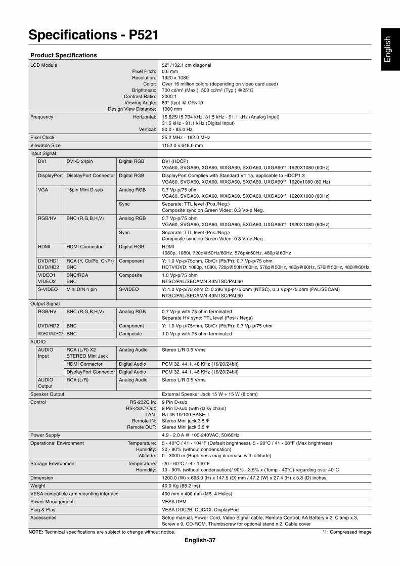
English-37
Eng
lishSpecifications - P521
Product Specifications
LCD Module 52" /132.1 cm diagonalPixel Pitch: 0.6 mmResolution: 1920 x 1080
Color: Over 16 million colors (depending on video card used)Brightness: 700 cd/m2 (Max.), 500 cd/m2 (Typ.) @25°C
Contrast Ratio: 2000:1Viewing Angle: 89° (typ) @ CR>10
Design View Distance: 1300 mm
Frequency Horizontal: 15.625/15.734 kHz, 31.5 kHz - 91.1 kHz (Analog Input)31.5 kHz - 91.1 kHz (Digital Input)
Vertical: 50.0 - 85.0 Hz
Pixel Clock 25.2 MHz - 162.0 MHz
Viewable Size 1152.0 x 648.0 mm
Input Signal
DVI DVI-D 24pin Digital RGB DVI (HDCP)VGA60, SVGA60, XGA60, WXGA60, SXGA60, UXGA60*1, 1920X1080 (60Hz)
DisplayPort DisplayPort Connector Digital RGB DisplayPort Complies with Standard V1.1a, applicable to HDCP1.3VGA60, SVGA60, XGA60, WXGA60, SXGA60, UXGA60*1, 1920x1080 (60 Hz)
VGA 15pin Mini D-sub Analog RGB 0.7 Vp-p/75 ohmVGA60, SVGA60, XGA60, WXGA60, SXGA60, UXGA60*1, 1920X1080 (60Hz)
Sync Separate: TTL level (Pos./Neg.)Composite sync on Green Video: 0.3 Vp-p Neg.
RGB/HV BNC (R,G,B,H,V) Analog RGB 0.7 Vp-p/75 ohmVGA60, SVGA60, XGA60, WXGA60, SXGA60, UXGA60*1, 1920X1080 (60Hz)
Sync Separate: TTL level (Pos./Neg.)Composite sync on Green Video: 0.3 Vp-p Neg.
HDMI HDMI Connector Digital RGB HDMI1080p, 1080i, 720p@50Hz/60Hz, 576p@50Hz, 480p@60Hz
DVD/HD1 RCA (Y, Cb/Pb, Cr/Pr) Component Y: 1.0 Vp-p/75ohm, Cb/Cr (Pb/Pr): 0.7 Vp-p/75 ohmDVD/HD2 BNC HDTV/DVD: 1080p, 1080i, 720p@50Hz/60Hz, 576p@50Hz, 480p@60Hz, 576i@50Hz, 480i@60Hz
VIDEO1 BNC/RCA Composite 1.0 Vp-p/75 ohmVIDEO2 BNC NTSC/PAL/SECAM/4.43NTSC/PAL60
S-VIDEO Mini DIN 4 pin S-VIDEO Y: 1.0 Vp-p/75 ohm C: 0.286 Vp-p/75 ohm (NTSC), 0.3 Vp-p/75 ohm (PAL/SECAM)NTSC/PAL/SECAM/4.43NTSC/PAL60
Output Signal
RGB/HV BNC (R,G,B,H,V) Analog RGB 0.7 Vp-p with 75 ohm terminatedSeparate HV sync: TTL level (Posi / Nega)
DVD/HD2 BNC Component Y: 1.0 Vp-p/75ohm, Cb/Cr (Pb/Pr): 0.7 Vp-p/75 ohm
VIDEO1/VIDEO2 BNC Composite 1.0 Vp-p with 75 ohm terminated
AUDIO
AUDIO RCA (L/R) X2 Analog Audio Stereo L/R 0.5 VrmsInput STEREO Mini Jack
HDMI Connector Digital Audio PCM 32, 44.1, 48 KHz (16/20/24bit)
DisplayPort Connector Digital Audio PCM 32, 44.1, 48 KHz (16/20/24bit)
AUDIO RCA (L/R) Analog Audio Stereo L/R 0.5 VrmsOutput
Speaker Output External Speaker Jack 15 W + 15 W (8 ohm)
Control RS-232C In: 9 Pin D-subRS-232C Out: 9 Pin D-sub (with daisy chain)
LAN: RJ-45 10/100 BASE-TRemote IN: Stereo Mini jack 3.5
Remote OUT: Stereo Mini jack 3.5
Power Supply 4.9 - 2.0 A @ 100-240VAC, 50/60Hz
Operational Environment Temperature: 5 - 40°C / 41 - 104°F (Default brightness), 5 - 20°C / 41 - 68°F (Max brightness)Humidity: 20 - 80% (without condensation)
Altitude: 0 - 3000 m (Brightness may decrease with altitude)
Storage Environment Temperature: -20 - 60°C / -4 - 140°FHumidity: 10 - 90% (without condensation)/ 90% - 3.5% x (Temp - 40°C) regarding over 40°C
Dimension 1200.0 (W) x 696.0 (H) x 147.5 (D) mm / 47.2 (W) x 27.4 (H) x 5.8 (D) inches
Weight 40.0 Kg (88.2 lbs)
VESA compatible arm mounting interface 400 mm x 400 mm (M6, 4 Holes)
Power Management VESA DPM
Plug & Play VESA DDC2B, DDC/CI, DisplayPort
Accessories Setup manual, Power Cord, Video Signal cable, Remote Control, AA Battery x 2, Clamp x 3,Screw x 9, CD-ROM, Thumbscrew for optional stand x 2, Cable cover
NOTE: Technical specifications are subject to change without notice. *1: Compressed image
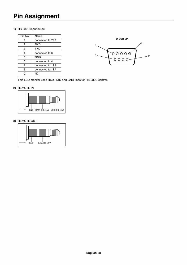
English-38
1) RS-232C input/output
Pin No Name
1 connected to 7&8
2 RXD
3 TXD
4 connected to 6
5 GND
6 connected to 4
7 connected to 1&8
8 connected to 1&7
9 NC
1
6
5
9
D-SUB 9P
This LCD monitor uses RXD, TXD and GND lines for RS-232C control.
2) REMOTE IN
Pin Assignment
3) REMOTE OUT
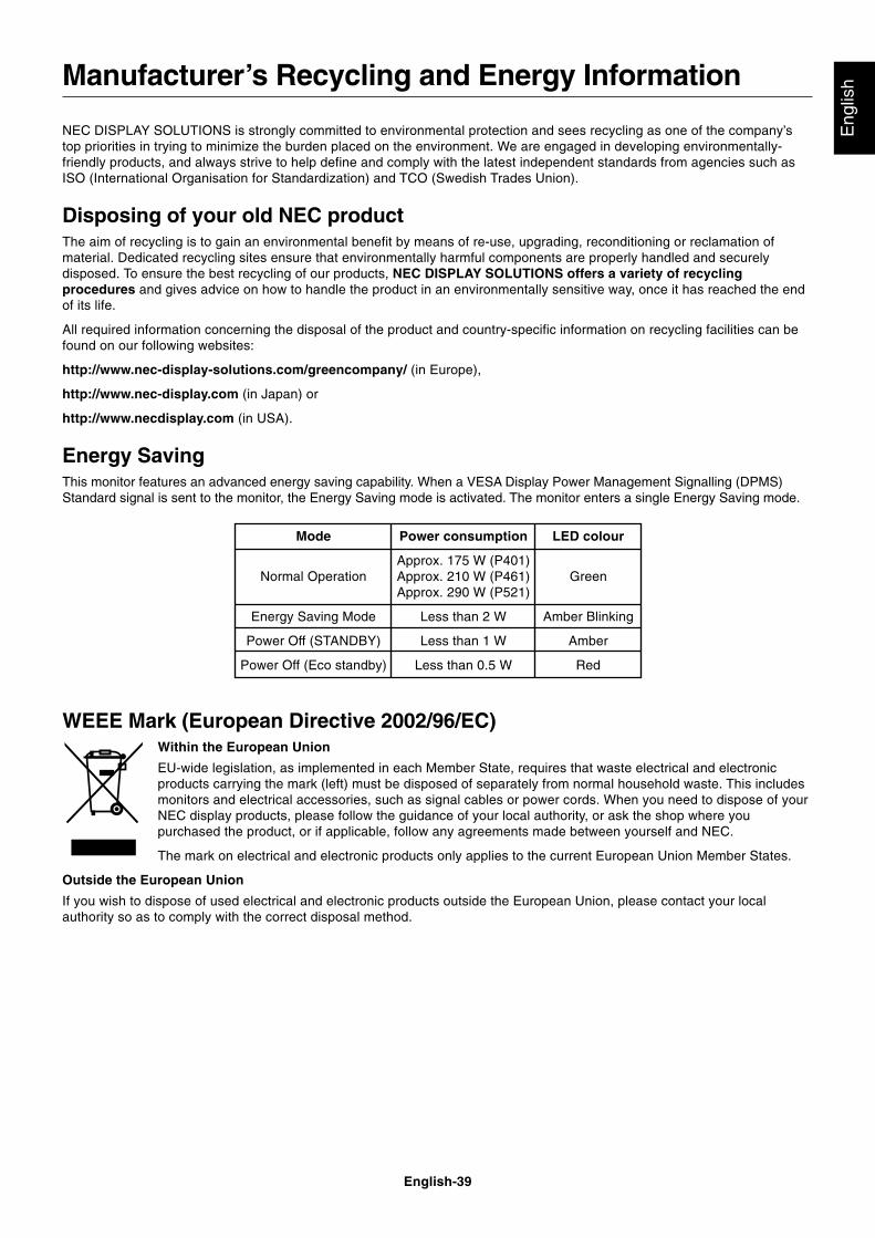
English-39
Eng
lish
NEC DISPLAY SOLUTIONS is strongly committed to environmental protection and sees recycling as one of the company’stop priorities in trying to minimize the burden placed on the environment. We are engaged in developing environmentally-friendly products, and always strive to help define and comply with the latest independent standards from agencies such asISO (International Organisation for Standardization) and TCO (Swedish Trades Union).
Disposing of your old NEC productThe aim of recycling is to gain an environmental benefit by means of re-use, upgrading, reconditioning or reclamation ofmaterial. Dedicated recycling sites ensure that environmentally harmful components are properly handled and securelydisposed. To ensure the best recycling of our products, NEC DISPLAY SOLUTIONS offers a variety of recyclingprocedures and gives advice on how to handle the product in an environmentally sensitive way, once it has reached the endof its life.
All required information concerning the disposal of the product and country-specific information on recycling facilities can befound on our following websites:
http://www.nec-display-solutions.com/greencompany/ (in Europe),
http://www.nec-display.com (in Japan) or
http://www.necdisplay.com (in USA).
Energy SavingThis monitor features an advanced energy saving capability. When a VESA Display Power Management Signalling (DPMS)Standard signal is sent to the monitor, the Energy Saving mode is activated. The monitor enters a single Energy Saving mode.
Manufacturer’s Recycling and Energy Information
WEEE Mark (European Directive 2002/96/EC)Within the European Union
EU-wide legislation, as implemented in each Member State, requires that waste electrical and electronicproducts carrying the mark (left) must be disposed of separately from normal household waste. This includesmonitors and electrical accessories, such as signal cables or power cords. When you need to dispose of yourNEC display products, please follow the guidance of your local authority, or ask the shop where youpurchased the product, or if applicable, follow any agreements made between yourself and NEC.
The mark on electrical and electronic products only applies to the current European Union Member States.
Outside the European Union
If you wish to dispose of used electrical and electronic products outside the European Union, please contact your localauthority so as to comply with the correct disposal method.
Mode
Normal Operation
Energy Saving Mode
Power Off (STANDBY)
Power Off (Eco standby)
LED colour
Green
Amber Blinking
Amber
Red
Power consumption
Approx. 175 W (P401)Approx. 210 W (P461)Approx. 290 W (P521)
Less than 2 W
Less than 1 W
Less than 0.5 W