multitask on pic16f877a
TRANSCRIPT
M AN777Multi-Tasking on the PIC16F877 with the Salvo™ RTOS
INTRODUCTION
This application note covers a Real-Time OperatingSystem (RTOS) running on a PIC16F877. The applica-tion is written in C using the HI-TECH C compiler.MPLAB® IDE is used as the Integrated DevelopmentEnvironment. This RTOS is unique, in that it is intendedfor microcontroller applications where memory isseverely limited. The application runs on a prototypePCB that monitors temperature, accepts user input anddisplays important temperature information.
RTOS OVERVIEW
Salvo™ is a full featured, cooperative, event driven,priority based, multi-tasking RTOS with highly efficientmemory utilization. It is ideally suited for use onMicrochip PICmicro® devices. Written in C, it is veryeasy to use, employing standardized RTOS methodsand terminology. This RTOS makes PICmicroprogramming a breeze, and includes:
• Over 40 callable user services in its API• Up to 16 separate dynamic task priority levels
• Support for multiple event types • Timer-based services • Minimal call … return stack usage
• Low interrupt latency and fast context switching
Every Salvo application must adhere to two “goldenrules”:
1. Each task must have at least one context switch.
2. Context switches may only occur in tasks.
For this application, Salvo was user-configured to pro-vide the basic multi-tasking kernel, along with binarysemaphore and message event services, as well astimer based delays. It automatically manages complexissues, like task scheduling, access to sharedresources, intertask communication, real-time delays,PICmicro RAM banking and interrupt control. With thismulti-tasking RTOS foundation in place, the applicationprogrammer can concentrate on quickly and efficientlyimplementing the desired system functionality.
SYSTEM DESCRIPTION
The prototype's hardware includes a 20 MHz crystal,four thermistors, four potentiometers, a serial port,EEPROM, four 7-segment LEDs, 16-button keypadand a piezo beeper. The phrase, “normal conditions,”will be used frequently in this application note, indicat-ing the demo board is in temperature monitoring modewith no alarm or user functions being executed.
The time-base is a 2 ms periodic interrupt derived fromTimer1. There are a total of eight tasks, four of whichare in the waiting state under normal conditions. Thereare five events, four of which are dependent upon thestatus of outside conditions (e.g., keypad entry, alarm)and one is required for resource control.
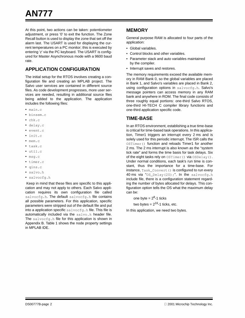
The thermistors are divided up into four zones (Z1, Z2,Z3, Z4). Each zone will be monitored to check if thetemperature is between the low and high thresholdtemperature range (set by user). The user sets the lowand high threshold temperatures by pressing theLow-High program button (see Figure 1).
FIGURE 1: KEYPAD CONFIGURATION
The low temperature is entered first, then the high;each entry is followed by a quick display of the enteredtemperature. A zone that is not within these parameterswill set off the Piezo alarm, simultaneously displayingthe zone number that set off the alarm. An alarm con-dition will also signal Task_Weeprom() with the zonenumber. Under normal conditions, once selected, theLEDs will always have a zone temperature displayed.The particular zone on display is dependent uponwhich zone button was pressed. Buttons 1 through 4have two functions (see Figure 1), potentiometer selec-tion and numerical. When one of these buttons ispressed (under normal conditions), the current potenti-ometer value is displayed on the LEDs.
Authors: Chris Valenti Microchip Technology Inc.
Andrew E. Kalman, Ph.D.Pumpkin, Inc.
SET POT-1 SET POT-2 SET POT-3 DISPLAYZONE 11 2 3
SET POT-4 5 6 DISPLAYZONE 24
7 8 9 DISPLAYZONE 3
LOW-HIGH PROGRAM
EXIT POT SETTING
ZONE RECALL
DISPLAYZONE 4
0
2001 Microchip Technology Inc. DS00777B-page 1
AN777
At this point, two actions can be taken: potentiometeradjustment, or press ‘0’ to exit the function. The ZoneRecall button is used to display the zone that set off thealarm last. The USART is used for displaying the cur-rent temperatures on a PC monitor; this is executed byentering 'z' via the PC keyboard. The USART is config-ured for Master Asynchronous mode with a 9600 baudrate.
APPLICATION CONFIGURATION
The initial setup for the RTOS involves creating a con-figuration file and creating an MPLAB project. TheSalvo user services are contained in different sourcefiles. As code development progresses, more user ser-vices are needed, resulting in additional source filesbeing added to the application. The applicationincludes the following files:
• main.c • binsem.c
• chk.c • delay.c • event.c
• init.c • mem.c • task.c
• util.c • msg.c • timer.c
• qins.c • salvo.h • salvocfg.h
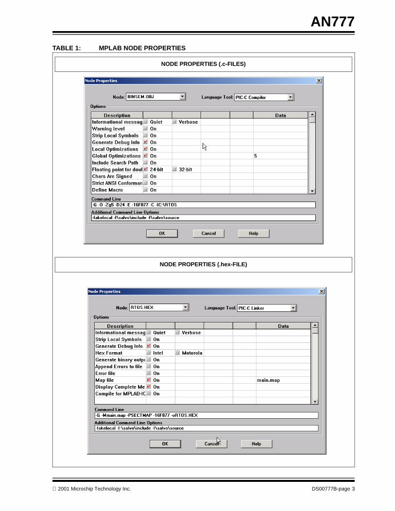
Keep in mind that these files are specific to this appli-cation and may not apply to others. Each Salvo appli-cation requires its own configuration file calledsalvocfg.h. The default salvocfg.h file containsall possible parameters. For this application, specificparameters were stripped out of the default file and putinto a application specific salvocfg.h file. This file isautomatically included via the salvo.h header file.The salvocfg.h file for this application is shown inAppendix B. Table 1 shows the node property settingsin MPLAB IDE.
MEMORY
General purpose RAM is allocated to four parts of theapplication:
• Global variables.
• Control blocks and other variables. • Parameter stack and auto variables maintained
by the compiler. • Interrupt saves and restores.
The memory requirements exceed the available mem-ory in RAM Bank 0, so the global variables are placedin Bank 1, and Salvo's variables are placed in Bank 2,using configuration options in salvocfg.h. Salvo'smessage pointers can access memory in any RAMbank and anywhere in ROM. The final code consists ofthree roughly equal portions: one-third Salvo RTOS,one-third HI-TECH C compiler library functions andone-third application specific code.
TIME-BASE
In an RTOS environment, establishing a true time-baseis critical for time-based task operations. In this applica-tion, Timer1 triggers an interrupt every 2 ms and issolely used for this periodic interrupt. The ISR calls theOSTimer() function and reloads Timer1 for another2 ms. The 2 ms interrupt is also known as the “systemtick rate” and forms the time basis for task delays. Sixof the eight tasks rely on OSTimer() via OSDelay().Under normal conditions, each task's run time is con-stant, thus the importance for a time-base. Forinstance, Task_Convert() is configured to run every40 ms via "OS_Delay(20);". In the salvocfg.hinclude file, there is a configuration statement regard-ing the number of bytes allocated for delays. This con-figuration option tells the OS what the maximum delaycan be:
one byte = 28-1 ticks
two bytes = 216-1 ticks, etc.
In this application, we need two bytes.
DS00777B-page 2 2001 Microchip Technology Inc.
AN777
TABLE 1: MPLAB NODE PROPERTIES
NODE PROPERTIES (.c-FILES)
NODE PROPERTIES (.hex-FILE)
2001 Microchip Technology Inc. DS00777B-page 3
AN777
TASK CONFIGURATION
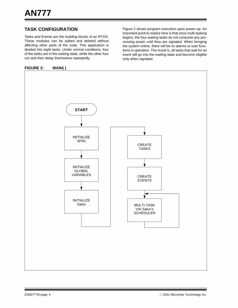
Tasks and Events are the building blocks of an RTOS.These modules can be added and deleted withoutaffecting other parts of the code. This application isdivided into eight tasks. Under normal conditions, fourof the tasks are in the waiting state, while the other fourrun and then delay themselves repeatedly.
Figure 2 shows program execution upon power-up. Animportant point to realize here is that once multi-taskingbegins, the four waiting tasks do not consume any pro-cessing power until they are signaled. When bringingthe system online, there will be no alarms or user func-tions in operation. The result is, all tasks that wait for anevent will go into the waiting state and become eligibleonly when signaled.
FIGURE 2: MAIN( )
START
INITIALIZESFRs
INITIALIZE
INITIALIZE
GLOBAL
Salvo
CREATE
MULTI-TASKVIA Salvo’s
SCHEDULER
VARIABLES
CREATE
EVENTS
TASKS
DS00777B-page 4 2001 Microchip Technology Inc.

AN777
The following is a detailed description of each task’spriorities, status, and responsibilities.
Task_Convert()
Priority: 1 Task has a priority of ‘1’ because we must determinethermistor temperatures to decide whether an alarmcondition exists.
Status: Runs every 40 milliseconds.
Responsibilities:
1. Converts the analog thermistor voltage into adigital value, then translates this value into aFahrenheit temperature.
2. This value is compared against the low and highthreshold temperatures [via ConvertTemp()]to determine if an alarm is necessary.
3. If no alarm is called then the other thermistorzones are converted.
Task_Alarm_On()
Priority: 1 This task also has a priority of ‘1’, but runs afterTask_Convert() in a round-robin fashion. Afterdetermining temperature, checking for zone alarms ismost important.
Status: Waits for an event.
Responsibilities:
1. Has the same priority as, and runs immediatelyafter, Task_Convert()at start-up.
2. Displays the zone number in alarm.
3. Turns the piezo beeper on and off.
Task_Display()
Priority: 2 Enables temperatures to be read from the display.
Status: Runs every 2 milliseconds.
Responsibilities:
1. Converts the temperature value to a format nec-essary for displaying on the LEDs.
2. Displays each converted digit.
Task_KeyPad()
Priority: 3 Keypad entry is infrequent and should not supercedethe prior tasks.
Status: Runs every 20 milliseconds.
Responsibilities:
1. Scans for the low-high entry.2. Scans for potentiometer adjustment entry.3. Scans for EEPROM recall entry.
4. Scans for zone display entry.
Task_Usart()
Priority: 4 Remote PC monitoring is only performed occasionallybecause usage is low.
Status: Runs every 800 milliseconds.
Responsibilities:
1. Scans for a PC keyboard entry (z).2. Prepares each zone temperature for PC monitor
display.3. Writes the Z1 string out to the HyperTerminal via
the USART.
Task_Weeprom()
Priority: 5 This task is only active when an alarm has occurred;therefore, it is used very little.
Status: Waits for an event.
Responsibilities:
1. Receives the zone number in alarm.2. Writes zone number to EEPROM.
3. I2C communication between the microcontrollerand EEPROM.
Task_Reeprom()
Priority: 6 This task is dependent upon Task_KeyPad() and isindependent of temperature and alarm status; there-fore, it is a very low priority.
Status: Waits for an event.
Responsibilities:
1. Reads the last address that Task_Weeprom()wrote to.
2. Reads the data within this address.
3. Displays the contents of the EEPROM addresson the LEDs (zone number).
Task_Pots()
Priority: 7 This task is least important because it is only used forsetting potentiometers, which do not affect any temper-ature or alarm statuses.
Status: Waits for an event.
Responsibilities:
1. According to the value passed to the local vari-able pot_val, the appropriate pot is selected foradjustment while displaying the current potenti-ometer A/D value on the LEDs.
2001 Microchip Technology Inc. DS00777B-page 5
AN777
EVENT CONFIGURATION
Semaphores and messages can represent events andthese methods of intertask communication are used intwo ways. The first and more obvious is done by signal-ing tasks. When a task is signaled, it transitions from awaiting state to an eligible state and finally a runningstate. ALARM, REEPROM, POTVAL and WEEPROM areused in this fashion. The DISPLAY event is used tocontrol a resource, quite different from the otherevents. Because the LED display is used by multipletasks and the LEDs and keypad both operate out ofPORTB on the microcontroller, PORTB has to be con-figured differently for both. The DISPLAY event is usedto manage access to PORTB. When control ofDISPLAY is placed around a group of statements, itcreates a sequence whereby a resource is acquired,used, and then released.
The process flow for Task_Alarm_On(), has the taskin one of three states: running, delayed, or waiting for anevent. Salvo manages task execution so the PICmicroalways runs the highest priority, eligible task. Whenevera particular task is running in this application, all othertasks are either delayed, waiting for an event, or eligibleto run.
Looking at Task_Alarm_On()when the code reachesOS_WaitBinSem (DISPLAY), if DISPLAY = 1, thenOS_WaitBinSem() flips it to ‘0’, and the followingcode is executed. When Salvo context switches viaOS_Delay(), any piece of the code that waits forDISPLAY will not run (DISPLAY = 0). After bothTask_Alarm_ON() and OS_Delay() are completed,DISPLAY is signaled (DISPLAY = 1) and allows thenext piece of code waiting for DISPLAY to run.
ALARM
Type: Message
Purpose: Signal Task_Alarm_On() from withinTask_Convert()(ConvertTemp()), with a mes-sage containing the zone number in alarm.
WEEPROM
Type: Message
Purpose: Signal Task_Weeprom() with a messagecontaining the zone number in alarm. This messageonly happens if there is an alarm and after the signalingof Task_Alarm_On().
REEPROM
Type: Binary Semaphore
Purpose: Signal Task_Reeprom() from withinTask_KeyPad() that the read EEPROM button hasbeen pressed. Signaling the binary semaphore causesthe waiting task to run.
POTVAL
Type: Message
Purpose: Signal Task_Pots() from withinTask_KeyPad() that a potentiometer adjustment but-ton has been pressed. Passes information containingthe potentiometer number to set for adjustment mode.
DISPLAY
Type: Binary Semaphore
Purpose: This semaphore is used to control aresource, this may be the function of the LEDs or thekeypad.
TIMING PERFORMANCE
Time management is a major responsibility for anRTOS. An application's response is dependent upontask execution times. The actual time between succes-sive executions of Task_Convert() was measuredas 40 milliseconds, with less than one system tick(2 ms) of timing jitter. When task delay times are calcu-lated, the time necessary for instructions within the taskmust also be taken into consideration.
SUMMARY
This application note demonstrates how easy it is toimplement a common embedded application into anRTOS environment. The temperature applicationshown here is just one of the many ways in which anRTOS can be applied. Some RTOS features that havenot been discussed may be what your applicationrequires. This includes counting semaphores and mes-sage queues, which are extended versions of the userservices used in this application. Only one interruptwas used (to maintain a time-base), but additionalinterrupt sources can be included for added real-timeresponse. After establishing an understanding of RTOSuser services, it's just a matter of adding more tasksand events to suit the demands of your application.
WEBSITES
Microchip Technology Inc. ............ www.microchip.com
Pumpkin, Inc.............................. www.pumpkininc.com
HI-TECH Software...............................www.htsoft.com
DS00777B-page 6 2001 Microchip Technology Inc.
AN777
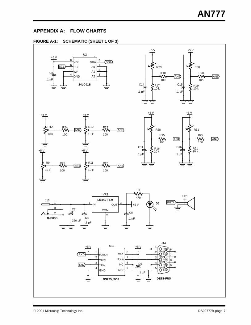
APPENDIX A: FLOW CHARTS
FIGURE A-1: SCHEMATIC (SHEET 1 OF 3)
AN2
SDA
R9
10 k
+5 V
C8
.1 µF
+5 V
+5 V
SCL
+5 V
C11
.1 µF
+5 V
C14
.1 µF
+5 V
C16
.1 µF
+5 V
C15
.1 µF
+5 V
1
3
2
J13
DJ005B
+5 V
R12
10 k
.1 µF
C4220 µF
C7
R28
R1610 k
R29
R1710 k
100
R26
100
R25 R11
10 k
100
R23
100
R24
+5 V
+5 V
100
R15
100
R18
C5
.1 µF
3OUT
1IN
2
COM
VR1
LM340T-5.0
+5 V
R10
10 k
D2
C6
.1 µF
R31
R2110 k
9PIN9
8PIN8
7PIN7
6PIN6
1PIN1
2PIN2
3PIN3
4PIN4
5PIN5
J14
DE9S-FRS
4GND
1RXOUT
2VDRV
3TXIN
5TXOUT
6NC
7RXIN
8VCC
U13
DS275_SO8
SP1
R30
R1910 k
470
R3
100
R22
100
R20
5SDA
1A0
2A1
3A2
4GND
7WP
6SCL
8VCC
U2
24LC01B
PIZO
AN0
AN1 AN3
AN5 AN6
AN7AN4
RXD
TXD
2001 Microchip Technology Inc. DS00777B-page 7
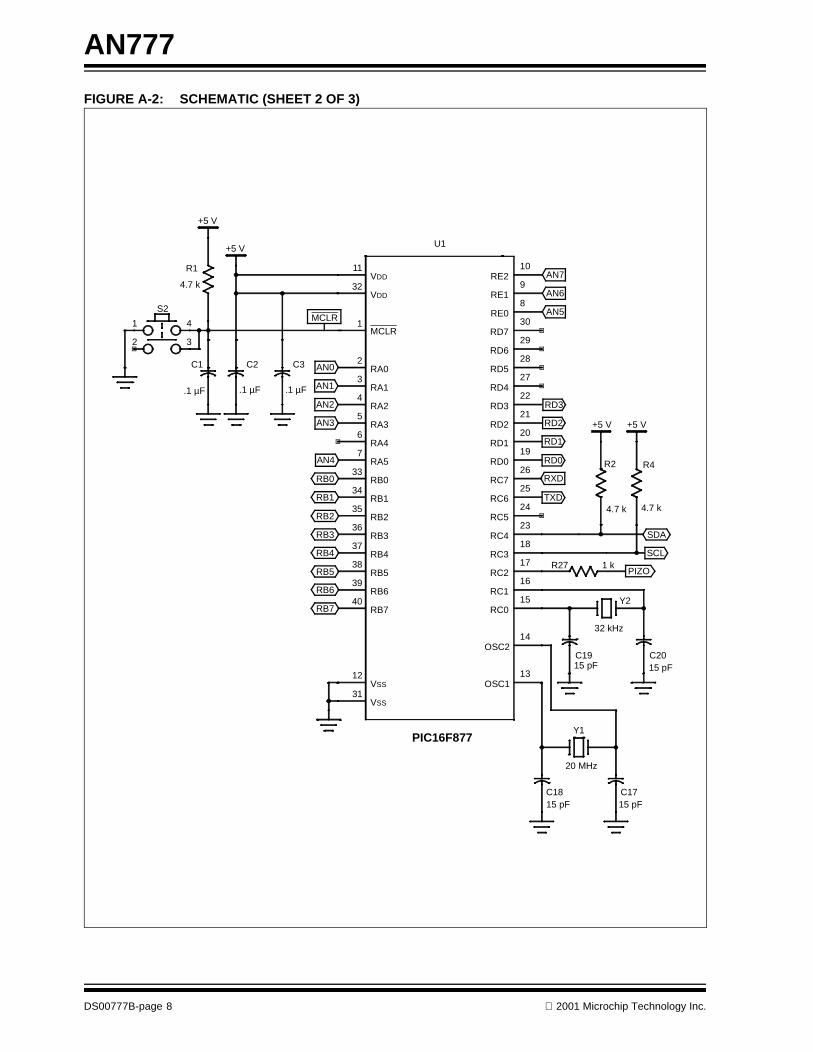
AN777
FIGURE A-2: SCHEMATIC (SHEET 2 OF 3)
MCLR
.1 µF
C2
+5 V
20 MHz
Y1
+5 V +5 V
4
32
1
S2
15 pFC18
15 pFC19
C1715 pF
R27 1 k
4.7 k
R2
.1 µF
C1
.1 µF
C3
4.7 k
R1
+5 V
C2015 pF
31VSS
32VDD
11VDD
1MCLR
2RA0
3RA1
4RA2
5RA3
6RA4
7RA5
33RB0
34RB1
35RB2
36RB3
37RB4
38RB5
39RB6
40RB7
12VSS
13OSC1
14OSC2
15RC0
16RC1
17RC2
18RC3
23RC4
24RC5
25RC6
26RC7
19RD0
20RD1
21RD2
22RD3
27RD4
28RD5
29RD6
30RD7
10RE2
9RE1
8RE0
U1
PIC16F877
R4
4.7 k
32 kHz
Y2
RB0
AN0
AN1
AN2
AN3
AN4
RB1
RB2
RB3
RB4
RB5
RB6
RB7
AN7
AN6
AN5
RD3
RD2
RD1
RD0
TXD
RXD
SDA
PIZO
SCL
DS00777B-page 8 2001 Microchip Technology Inc.
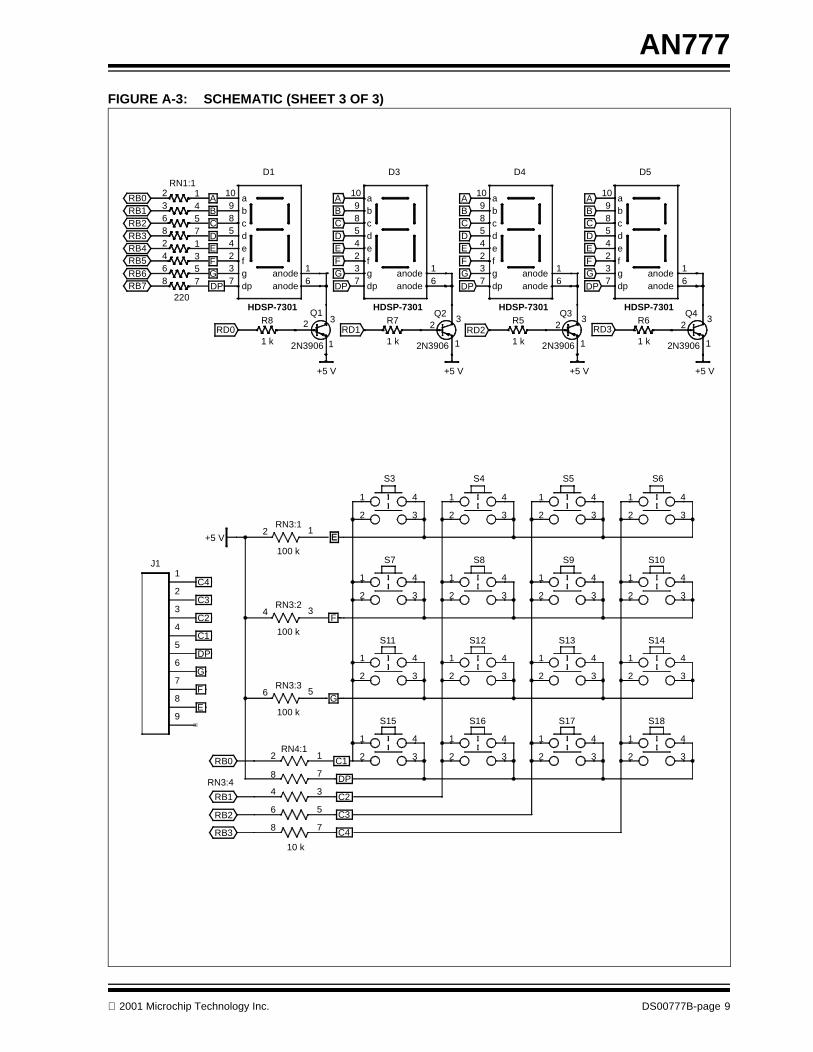
AN777
FIGURE A-3: SCHEMATIC (SHEET 3 OF 3)
2
1
3Q1
2N3906
2
1
3Q2
2N3906
2
1
3Q4
2N3906
+5 V +5 V +5 V +5 V
4 3
56
1 k
R8
6 5
7812
3 42 1
RN1:1
2
1
3Q3
2N39061 k
R7
1 k
R5
1 k
R6
8 7
220
9 b
5 d4 e2 f3 g7 dp
8 c
10 a
1anode6anode
D4
HDSP-7301
9 b
5 d4 e2 f3 g7 dp
8 c
10 a
1anode6anode
D3
HDSP-7301
9 b
5 d4 e2 f3 g7 dp
8 c
10 a
1anode6anode
D1
HDSP-7301
9 b
5 d4 e2 f3 g7 dp
8 c
10 a
1anode6anode
D5
HDSP-7301
RB0
RD0 RD1 RD2 RD3
ABCDEFGDP
RB1RB2RB3RB4RB5RB6RB7
A
DP
BCDEFG
A
DP
BCDEFG
ABCDEFG
+5 V
4
32
1
S16
4
32
1
S17
4
32
1
S18
4
32
1
S8
4
32
1
S4
4
32
1
S9
4
32
1
S5
4
32
1
S10
4
32
1
S6
4
32
1
S12
4
32
1
S13
4
32
1
S14
4 3
6 5
8 7
10 k
4
32
1
S15
2 1RN4:1
4 3RN3:2
100 k
2 1RN3:1
100 k
6 5RN3:3
100 k
4
32
1
S7
4
32
1
S3
1
2
3
4
5
6
7
8
9
J1
4
32
1
S11
8 7RN3:4
RB0
C4
EG
F
E
DP
G
C3
C2
DP
C1
C4
C3
C2
C1
F
RB1
RB2
RB3
DP
E
2001 Microchip Technology Inc. DS00777B-page 9
AN777
Software License Agreement
The software supplied herewith by Microchip Technology Incorporated (the “Company”) for its PICmicro® Microcontroller isintended and supplied to you, the Company’s customer, for use solely and exclusively on Microchip PICmicro Microcontroller prod-ucts.The software is owned by the Company and/or its supplier, and is protected under applicable copyright laws. All rights are reserved.Any use in violation of the foregoing restrictions may subject the user to criminal sanctions under applicable laws, as well as to civilliability for the breach of the terms and conditions of this license.THIS SOFTWARE IS PROVIDED IN AN “AS IS” CONDITION. NO WARRANTIES, WHETHER EXPRESS, IMPLIED OR STATU-TORY, INCLUDING, BUT NOT LIMITED TO, IMPLIED WARRANTIES OF MERCHANTABILITY AND FITNESS FOR A PARTICU-LAR PURPOSE APPLY TO THIS SOFTWARE. THE COMPANY SHALL NOT, IN ANY CIRCUMSTANCES, BE LIABLE FORSPECIAL, INCIDENTAL OR CONSEQUENTIAL DAMAGES, FOR ANY REASON WHATSOEVER.
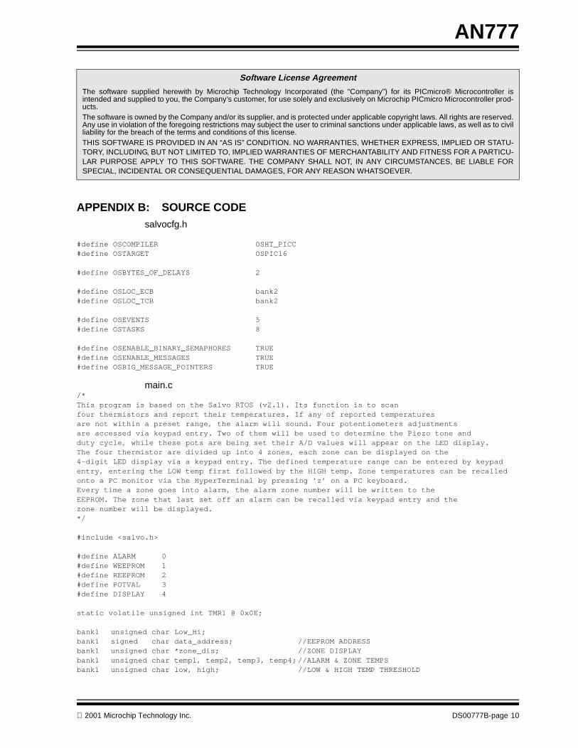
APPENDIX B: SOURCE CODEsalvocfg.h
#define OSCOMPILER OSHT_PICC#define OSTARGET OSPIC16
#define OSBYTES_OF_DELAYS 2
#define OSLOC_ECB bank2#define OSLOC_TCB bank2
#define OSEVENTS 5#define OSTASKS 8
#define OSENABLE_BINARY_SEMAPHORES TRUE#define OSENABLE_MESSAGES TRUE#define OSBIG_MESSAGE_POINTERS TRUE
main.c/*This program is based on the Salvo RTOS (v2.1). Its function is to scan four thermistors and report their temperatures. If any of reported temperaturesare not within a preset range, the alarm will sound. Four potentiometers adjustments are accessed via keypad entry. Two of them will be used to determine the Piezo tone and duty cycle, while these pots are being set their A/D values will appear on the LED display. The four thermistor are divided up into 4 zones, each zone can be displayed on the 4-digit LED display via a keypad entry. The defined temperature range can be entered by keypad entry, entering the LOW temp first followed by the HIGH temp. Zone temperatures can be recalledonto a PC monitor via the HyperTerminal by pressing ’z’ on a PC keyboard.Every time a zone goes into alarm, the alarm zone number will be written to the EEPROM. The zone that last set off an alarm can be recalled via keypad entry and thezone number will be displayed.*/
#include <salvo.h>
#define ALARM 0#define WEEPROM 1#define REEPROM 2#define POTVAL 3#define DISPLAY 4
static volatile unsigned int TMR1 @ 0x0E;
bank1 unsigned char Low_Hi;bank1 signed char data_address; //EEPROM ADDRESSbank1 unsigned char *zone_dis; //ZONE DISPLAYbank1 unsigned char temp1, temp2, temp3, temp4;//ALARM & ZONE TEMPSbank1 unsigned char low, high; //LOW & HIGH TEMP THRESHOLD
2001 Microchip Technology Inc. DS00777B-page 10
AN777
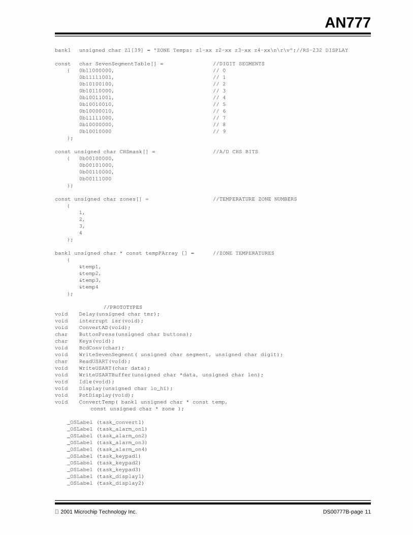
bank1 unsigned char Z1[39] = "ZONE Temps: z1-xx z2-xx z3-xx z4-xx\n\r\v";//RS-232 DISPLAY
const char SevenSegmentTable[] = //DIGIT SEGMENTS{ 0b11000000, // 0
0b11111001, // 10b10100100, // 20b10110000, // 30b10011001, // 40b10010010, // 50b10000010, // 60b11111000, // 70b10000000, // 80b10010000 // 9
}; const unsigned char CHSmask[] = //A/D CHS BITS
{ 0b00100000,0b00101000,0b00110000,0b00111000
};
const unsigned char zones[] = //TEMPERATURE ZONE NUMBERS{
1,2,3,4
};
bank1 unsigned char * const tempPArray [] = //ZONE TEMPERATURES{
&temp1,&temp2,&temp3,&temp4
};
//PROTOTYPESvoid Delay(unsigned char tmr);void interrupt isr(void);void ConvertAD(void);char ButtonPress(unsigned char buttons);char Keys(void);void BcdConv(char);void WriteSevenSegment( unsigned char segment, unsigned char digit);char ReadUSART(void);void WriteUSART(char data);void WriteUSARTBuffer(unsigned char *data, unsigned char len);void Idle(void);void Display(unsigned char lo_hi);void PotDisplay(void);void ConvertTemp( bank1 unsigned char * const temp, const unsigned char * zone );
_OSLabel (task_convert1)_OSLabel (task_alarm_on1)_OSLabel (task_alarm_on2)_OSLabel (task_alarm_on3)_OSLabel (task_alarm_on4)_OSLabel (task_keypad1)_OSLabel (task_keypad2)_OSLabel (task_keypad3)_OSLabel (task_display1)_OSLabel (task_display2)
2001 Microchip Technology Inc. DS00777B-page 11

AN777
_OSLabel (task_usart1)_OSLabel (task_weeprom1)_OSLabel (task_reeprom1)_OSLabel (task_reeprom2)_OSLabel (task_reeprom3)_OSLabel (task_pots1)_OSLabel (task_pots2)
//**************************( FUNCTIONS )****************************************
void Delay(unsigned char tmr) //TIMER0 MAX TIMEOUT = 13ms{
TMR0 = 255 - tmr;T0IF = 0;while(T0IF==0);
}
#pragma interrupt_level 0void interrupt isr(void) //TIMER1 2ms PERIODIC INTERRUPT{
if(TMR1IF){
TMR1IF = 0;TMR1 -= 5000;OSTimer();
}}
void ConvertAD(void) //A/D CONVERSION{
Delay(1); ADGO = 1; while(ADGO);
}
char ButtonPress(unsigned char buttons){
unsigned char Col_Row; //FIND BUTTON PRESSPORTB = buttons;Delay(55);Col_Row = PORTB;return Col_Row;
}
char Keys(void) //NUMBER SELECTION{
char KeyVal = 10; //BUTTON NUMBER PRESSED PORTD = 0x0F; //LEDs OFFTRISB = 0xF0; //RB7:RB4=INPUTS,RB3:RB0=OUTPUTS
while(KeyVal == 10){
switch(ButtonPress(0b00001110)){case 0xEE:
KeyVal = 0b00000001; //#1break;
case 0xDE:KeyVal = 0b00000100; //#4break;
DS00777B-page 12 2001 Microchip Technology Inc.
AN777
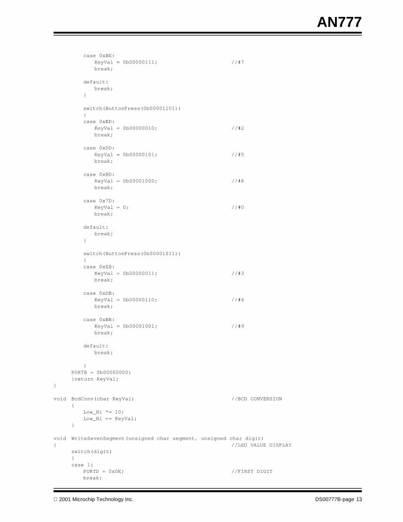
case 0xBE:KeyVal = 0b00000111; //#7break;
default:break;
}
switch(ButtonPress(0b00001101)){case 0xED:
KeyVal = 0b00000010; //#2break;
case 0xDD:KeyVal = 0b00000101; //#5break;
case 0xBD:KeyVal = 0b00001000; //#8break;
case 0x7D:KeyVal = 0; //#0break;
default:break;
}
switch(ButtonPress(0b00001011)){case 0xEB:
KeyVal = 0b00000011; //#3break;
case 0xDB:KeyVal = 0b00000110; //#6break;
case 0xBB:KeyVal = 0b00001001; //#9break;
default:break;
}PORTB = 0b00000000;}return KeyVal;
}
void BcdConv(char KeyVal) //BCD CONVERSION{
Low_Hi *= 10;Low_Hi += KeyVal;
}
void WriteSevenSegment(unsigned char segment, unsigned char digit){ //LED VALUE DISPLAY
switch(digit){case 1:
PORTD = 0x0E; //FIRST DIGITbreak;
2001 Microchip Technology Inc. DS00777B-page 13
AN777
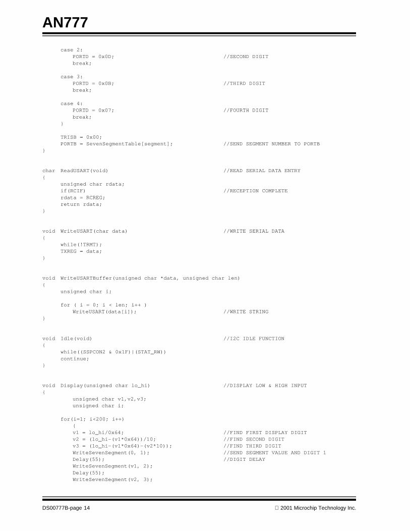
case 2:PORTD = 0x0D; //SECOND DIGITbreak;
case 3: PORTD = 0x0B; //THIRD DIGITbreak;
case 4:PORTD = 0x07; //FOURTH DIGITbreak;
}
TRISB = 0x00;PORTB = SevenSegmentTable[segment]; //SEND SEGMENT NUMBER TO PORTB
}
char ReadUSART(void) //READ SERIAL DATA ENTRY{
unsigned char rdata;if(RCIF) //RECEPTION COMPLETErdata = RCREG;return rdata;
}
void WriteUSART(char data) //WRITE SERIAL DATA{
while(!TRMT);TXREG = data;
}
void WriteUSARTBuffer(unsigned char *data, unsigned char len){
unsigned char i;
for ( i = 0; i < len; i++ )WriteUSART(data[i]); //WRITE STRING
}
void Idle(void) //I2C IDLE FUNCTION{
while((SSPCON2 & 0x1F)|(STAT_RW)) continue;
}
void Display(unsigned char lo_hi) //DISPLAY LOW & HIGH INPUT{
unsigned char v1,v2,v3;unsigned char i;
for(i=1; i<200; i++){v1 = lo_hi/0x64; //FIND FIRST DISPLAY DIGITv2 = (lo_hi-(v1*0x64))/10; //FIND SECOND DIGITv3 = (lo_hi-(v1*0x64)-(v2*10)); //FIND THIRD DIGIT WriteSevenSegment(0, 1); //SEND SEGMENT VALUE AND DIGIT 1Delay(55); //DIGIT DELAYWriteSevenSegment(v1, 2);Delay(55);WriteSevenSegment(v2, 3);
DS00777B-page 14 2001 Microchip Technology Inc.
AN777
Delay(55);WriteSevenSegment(v3, 4);Delay(55);}
}
void PotDisplay(void){
unsigned char v1,v2,v3;for(;;){
ConvertAD();v1 = ADRESH/0x64; //FIND FIRST DISPLAY DIGITv2 = (ADRESH-(v1*0x64))/10; //FIND SECOND DIGITv3 = (ADRESH-(v1*0x64)-(v2*10)); //FIND THIRD DIGIT ;WriteSevenSegment(v1, 2); //SEND SEGMENT VALUE AND DIGIT 2Delay(15);WriteSevenSegment(v2, 3); //SEND SEGMENT VALUE AND DIGIT 3Delay(15);WriteSevenSegment(v3, 4); //SEND SEGMENT VALUE AND DIGIT 4Delay(15);
PORTD = 0x0F; //PREPARE FOR KEYPAD USETRISB = 0xF0;if(ButtonPress(0b00001101) == 0x7D)break;
}}
void ConvertTemp( bank1 unsigned char * const temp, const unsigned char * zone ){ float adresh;
adresh = ADRESH;*temp = ( (.538) + (.444*(adresh) ) + (.001*(adresh)*(adresh) ) );
if ( ( low > *temp ) || ( *temp > high ) ) {
OSSignalMsg(ALARM, (OStypeMsgP) zone); //SIGNAL task_alarm() W/ ZONE #OSSignalMsg(WEEPROM, (OStypeMsgP) zone); //SIGNAL task_weeprom() W/ ZONE #
}}
//**************************( TASKS )*******************************************//**********************************************************************************
void Task_Convert(void){
static unsigned char i = 0;
for(;;){
ADCON0 &= ~0b00111000; //CLEAR CHS BITSADCON0 |= CHSmask[i]; //SELECT CHSConvertAD(); //CONVERT CHSConvertTemp(tempPArray[i], &zones[i] );
if ( ++i > 3 ) i = 0;
OS_Delay(20,task_convert1); //DELAYED FOR 40ms}
}
2001 Microchip Technology Inc. DS00777B-page 15
AN777
void Task_Alarm_On(void) //WAITING TASK{
OStypeMsgP msgP;
for(;;){
OS_WaitMsg(ALARM, &msgP, task_alarm_on1);OS_WaitBinSem(DISPLAY, task_alarm_on2);WriteSevenSegment(* ( const unsigned char *) msgP, 4);//DISPLAY ALARM ZONECCP1CON = 0x0F;OS_Delay(200, task_alarm_on3);CCP1CON = 0;OS_Delay(200, task_alarm_on4);OSSignalBinSem(DISPLAY);
}}
void Task_Keypad(void){
static char pot;for(;;){
OS_WaitBinSem(DISPLAY, task_keypad1);PORTD = 0x0F; //LEDs OFFTRISB = 0xF0; //RB7:RB4 = INPUTS,RB3:RB0 = OUTPUTS
switch(ButtonPress(0b00001110) ){case 0x7E: //SET LOW AND HIGH TEMPS
PORTD = 0x00; //TURN ON DIGITS TOTRISB = 0x00; // SHOW TEMP SETTINGPORTB = 0x00; // ACTIVATIONOS_Delay(200, task_keypad2);
//GET LOW TEMPERATURE LIMITPEIE = 0; //INTERRUPT DISABLED
Low_Hi = 0;BcdConv(Keys()); //GET 1ST DIGITwhile( PORTB != 0xF0 );
BcdConv(Keys()); //GET 2ND DIGITwhile( PORTB != 0xF0 );
BcdConv(Keys()); //GET 3RD DIGITlow = Low_Hi;
Display(low); //DISPLAY LOW TEMPPORTD = 0x0F; //LEDs OFFTRISB = 0xF0; //RB7:RB4 = INPUTS,RB3:RB0 = OUTPUTS
//GET HIGH TEMPERATURE LIMIT
Low_Hi = 0;BcdConv(Keys()); //GET 1ST DIGITwhile( PORTB != 0xF0 );
BcdConv(Keys()); //GET 2ND DIGITwhile( PORTB != 0xF0 );
BcdConv(Keys()); //GET 3RD DIGIThigh = Low_Hi;Display(high); //DISPLAY HIGH TEMPPEIE = 1; //INTERRUPT RE-ENABLEDbreak;
DS00777B-page 16 2001 Microchip Technology Inc.
AN777
//POTENTIOMETER SELECTION
case 0xEE: //#1pot = 1;OSSignalMsg(POTVAL,(OStypeMsgP)&pot); //SIGNAL task_pots() W/ POT-1break;
case 0xDE: //#4pot = 4;OSSignalMsg(POTVAL,(OStypeMsgP)&pot); //SIGNAL task_pots() W/ POT-4break;
default:break;
}
if(ButtonPress(0b00001101) == 0xED) //#2{
pot = 2;OSSignalMsg(POTVAL,(OStypeMsgP)&pot); //SIGNAL task_pots() W/ POT-2
}
switch(ButtonPress(0b00001011) ){case 0xEB:
pot = 3; //#3 OSSignalMsg(POTVAL,(OStypeMsgP)&pot); //SIGNAL task_pots() W/ POT-3break;
//EEPROM BUTTONcase 0x7B:
OSSignalBinSem(REEPROM); //SIGNAL task_reeprom()break;
default:break;
}
//ZONE BUTTONS
switch(ButtonPress(0b00000111)){case 0xE7:
zone_dis = &temp1; //ZONE 1 BUTTONbreak;
case 0xD7:zone_dis = &temp2; //ZONE 2 BUTTONbreak;
case 0xB7:zone_dis = &temp3; //ZONE 3 BUTTONbreak;
case 0x77:zone_dis = &temp4; //ZONE 4 BUTTONbreak;
default:break;
}
2001 Microchip Technology Inc. DS00777B-page 17
AN777
OSSignalBinSem(DISPLAY);OS_Delay(10,task_keypad3); //DELAYED FOR 20ms
}}
void Task_Display(void){
unsigned char v1,v2,v3;unsigned char dis_temp;
for(;;){
OS_WaitBinSem(DISPLAY, task_display1);
dis_temp = *zone_dis;v1 = dis_temp/0x64; //FIND FIRST DISPLAY DIGITv2 = (dis_temp-(v1*0x64))/10; //FIND SECOND DIGITv3 = (dis_temp-(v1*0x64)-(v2*10)); //FIND THIRD DIGIT WriteSevenSegment(0, 1); //SEND SEGMENT VALUE AND DIGIT 1Delay(100); //DIGIT-ON DELAYWriteSevenSegment(v1, 2);Delay(100);WriteSevenSegment(v2, 3);Delay(100);WriteSevenSegment(v3, 4);Delay(100);PORTB = 0xFF; // TURN OFF LAST DIGIT
OSSignalBinSem(DISPLAY);OS_Delay(1, task_display2); // DELAYED FOR 2ms
}}
void Task_Usart(void){
unsigned char v1,v2,v3,v2A,v3A,v2B,v3B,v2C,v3C,v2D,v3D;for(;;){
ReadUSART();if(ReadUSART() == 0x7A) // ASCII CHARACTER z{v1 = temp1 / 0x64; // CONVERT TEMP1 FOR DISPLAYv2 = (temp1 - (v1*0x64))/10;v3 = (temp1 - (v1*0x64) - (v2*10));v2A = v2, v3A = v3;
v1 = temp2 / 0x64; // TEMP2 v2 = (temp2 - (v1*0x64))/10;v3 = (temp2 - (v1*0x64) - (v2*10));v2B = v2, v3B = v3;
v1 = temp3 / 0x64; // TEMP3 v2 = (temp3 - (v1*0x64))/10;v3 = (temp3 - (v1*0x64) - (v2*10));v2C = v2, v3C = v3;
v1 = temp4 / 0x64; // TEMP4 v2 = (temp4 - (v1*0x64))/10;v3 = (temp4 - (v1*0x64) - (v2*10));v2D = v2, v3D = v3;
DS00777B-page 18 2001 Microchip Technology Inc.
AN777
Z1[15] = v2A + ’0’;Z1[16] = v3A + ’0’;Z1[21] = v2B + ’0’;Z1[22] = v3B + ’0’;Z1[27] = v2C + ’0’;Z1[28] = v3C + ’0’;Z1[33] = v2D + ’0’;Z1[34] = v3D + ’0’;WriteUSARTBuffer(Z1,39); //WRITE STRING Z1 FOR 39 BYTES
}
OS_Delay(400, task_usart1); //DELAYED FOR 800ms}
}
void Task_Weeprom(void) //WAITING TASK{
OStypeMsgPalarm_zoneP;char word;
for(;;){
OS_WaitMsg(WEEPROM, &alarm_zoneP, task_weeprom1);word = *(const unsigned char*) alarm_zoneP;
SEN = 1; //START ENABLEDwhile(SEN); //WAIT UNTIL START IS OVERSSPBUF = 0b10100000; //CONTROL BYTEIdle(); //ENSURE MODULE IS IDLEif(!ACKSTAT); //LOOK FOR ACKelse
break;
SSPBUF = data_address; //ADDRESS BYTEIdle(); //ENSURE MODULE IS IDLEif(!ACKSTAT); //LOOK FOR ACKelse
break;
SSPBUF = word; //DATA BYTE (ZONES: 1,2,3 or 4)Idle(); //ENSURE MODULE IS IDLEif(!ACKSTAT) //LOOK FOR ACK{ PEN = 1; //STOP ENABLED
while(PEN); //WAIT UNTIL STOP IS OVER}else
break;}
}
void Task_Reeprom(void){
char word;for(;;) //WAITING TASK{
OS_WaitBinSem(REEPROM,task_reeprom1);
Idle(); //ENSURE MODULE IS IDLESEN = 1; //START ENABLEDwhile(SEN); //WAIT UNTIL START IS OVER
SSPBUF = 0b10100000; //CONTROL BYTE (write)Idle(); //ENSURE MODULE IS IDLEif(!ACKSTAT); //LOOK FOR ACK
2001 Microchip Technology Inc. DS00777B-page 19
AN777
elsebreak;
SSPBUF = data_address; //ADDRESS BYTE (write)Idle(); //ENSURE MODULE IS IDLEif(!ACKSTAT); //LOOK FOR ACKelse
break;RSEN = 1; //REPEAT START CONDITIONwhile(RSEN); //WAIT UNTIL RESTART IS OVER
SSPBUF = 0b10100001; //CONTROL BYTE (read)Idle(); //ENSURE MODULE IS IDLEif(!ACKSTAT); //LOOK FOR ACKelse
break;
RCEN = 1; //ENABLE RECEIVEwhile(RCEN); //WAIT UNTIL RECEIVE IS OVER
ACKDT = 1; //NO ACKACKEN = 1;while(ACKEN); //WAIT UNTIL ACK IS FINISHED
PEN = 1; //STOP ENABLEDwhile(PEN); //WAIT UNTIL STOP IS OVER
word = SSPBUF; //WRITE DATA TO VARIABLE++data_address; //MOVE ADDRESS TO NEXT SPACE
OS_WaitBinSem(DISPLAY, task_reeprom2);WriteSevenSegment(word, 3); //DISPLAY ZONE OF LAST ALARMOS_Delay(200, task_reeprom3);OSSignalBinSem(DISPLAY);
}}void Task_Pots(void) //WAITING TASK{
OStypeMsgP pot_valP;char pot_val;
for(;;){
OS_WaitMsg(POTVAL, &pot_valP, task_pots1);pot_val = *(char*) pot_valP;OS_WaitBinSem(DISPLAY, task_pots2);
switch(pot_val){
case 1:CHS2=0, CHS1=0, CHS0=0; //AN0 - PIEZO "TONE" (PWM PERIOD)PotDisplay();PR2 = ADRESH;break;
case 2:CHS2=0, CHS1=0, CHS0=1; //DISPLAY A/D VALUEPotDisplay();break;
case 3:CHS2=0, CHS1=1, CHS0=0; //DISPLAY A/D VALUEPotDisplay();break;
case 4:CHS2=0, CHS1=1, CHS0=1; // AN3 - FOR PIEZO DUTY CYCLEPotDisplay();CCPR1L = ADRESH;
DS00777B-page 20 2001 Microchip Technology Inc.
AN777
break;}
OSSignalBinSem(DISPLAY);}
}
//*****************************( MAIN )****************************************//*******************************************************************************
void main(void){
TXSTA = 0b10100100; //TRANSMIT RCSTA = 0b10010000; //RECEIVE SPBRG = 0x81; //BAUD RATETRISC6 = 0,TRISC7 = 1; //TXD OUTPUT & RXD INPUT
TRISC3 = 1,TRISC4 = 1; //SCL & SDA - I2CSSPADD = 0x32; //I2C BAUD RATE (MASTER MODE)SSPCON = 0b00101000; //ENABLE SDA & SCL, S-PORT MODE-MASTER
ADCON0 = 0b01000001; //A/D CONFIG
OPTION = 0b10000101; //TIMER0 CONFIG
T1CON = 0b00010101; //TIMER1 CONFIG (system tick rate)TMR1IE = 1; //ENABLE INTERRUPTTMR1IF = 0; //CLEAR FLAG
TRISC2 = 0; //PIEZOCCPR1L = 0x80,CCP1X=0,CCP1Y=0; //PWM DUTY CYCLET2CON = 0b00000101; //TIMER2 PRESCALE = 4 (PWM)
GIE = 1, PEIE = 1; //ENABLE GLOBAL & PERIPHERAL INTERRUPTS
TRISD = 0x00; //PORTD OUTPUT-DIGITSlow=20,high=170; //INITIAL TEMPERATURE RANGEdata_address = 0x00; //FIRST EEPROM WRITE
OSInit(); //ID PRIORITY
OSCreateTask(Task_Convert, 0, 1);OSCreateTask(Task_Alarm_On, 1, 1);OSCreateTask(Task_Keypad, 2, 3);OSCreateTask(Task_Display, 3, 2);OSCreateTask(Task_Usart, 4, 4);OSCreateTask(Task_Weeprom, 5, 5);OSCreateTask(Task_Reeprom, 6, 6);OSCreateTask(Task_Pots, 7, 7);
OSCreateMsg(ALARM, (OStypeMsgP) 0);OSCreateMsg(WEEPROM,(OStypeMsgP) 0);OSCreateBinSem(REEPROM, 0);OSCreateMsg(POTVAL, (OStypeMsgP) 0);OSCreateBinSem(DISPLAY, 1);
for(;;)OSSched();
}
2001 Microchip Technology Inc. DS00777B-page 21
AN777
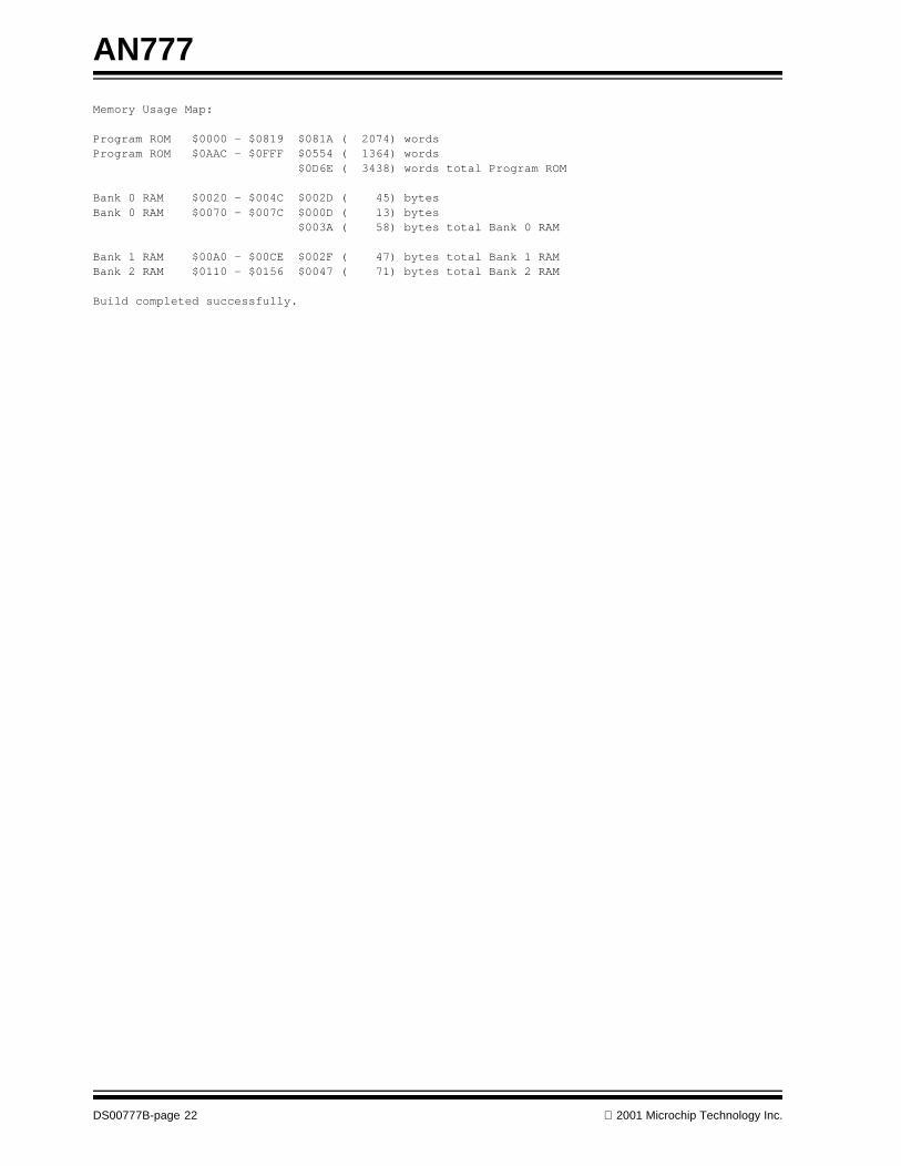
Memory Usage Map:
Program ROM $0000 - $0819 $081A ( 2074) wordsProgram ROM $0AAC - $0FFF $0554 ( 1364) words $0D6E ( 3438) words total Program ROM
Bank 0 RAM $0020 - $004C $002D ( 45) bytesBank 0 RAM $0070 - $007C $000D ( 13) bytes $003A ( 58) bytes total Bank 0 RAM
Bank 1 RAM $00A0 - $00CE $002F ( 47) bytes total Bank 1 RAM Bank 2 RAM $0110 - $0156 $0047 ( 71) bytes total Bank 2 RAM
Build completed successfully.
DS00777B-page 22 2001 Microchip Technology Inc.
Note the following details of the code protection feature on PICmicro® MCUs.
• The PICmicro family meets the specifications contained in the Microchip Data Sheet.• Microchip believes that its family of PICmicro microcontrollers is one of the most secure products of its kind on the market today,
when used in the intended manner and under normal conditions.• There are dishonest and possibly illegal methods used to breach the code protection feature. All of these methods, to our knowl-
edge, require using the PICmicro microcontroller in a manner outside the operating specifications contained in the data sheet. The person doing so may be engaged in theft of intellectual property.
• Microchip is willing to work with the customer who is concerned about the integrity of their code.• Neither Microchip nor any other semiconductor manufacturer can guarantee the security of their code. Code protection does not
mean that we are guaranteeing the product as “unbreakable”.• Code protection is constantly evolving. We at Microchip are committed to continuously improving the code protection features of
our product.
If you have any further questions about this matter, please contact the local sales office nearest to you.
Information contained in this publication regarding deviceapplications and the like is intended through suggestion onlyand may be superseded by updates. It is your responsibility toensure that your application meets with your specifications.No representation or warranty is given and no liability isassumed by Microchip Technology Incorporated with respectto the accuracy or use of such information, or infringement ofpatents or other intellectual property rights arising from suchuse or otherwise. Use of Microchip’s products as critical com-ponents in life support systems is not authorized except withexpress written approval by Microchip. No licenses are con-veyed, implicitly or otherwise, under any intellectual propertyrights.
2001 Microchip Technology Inc.
Trademarks
The Microchip name and logo, the Microchip logo, PIC, PICmicro,PICMASTER, PICSTART, PRO MATE, KEELOQ, SEEVAL,MPLAB and The Embedded Control Solutions Company are reg-istered trademarks of Microchip Technology Incorporated in theU.S.A. and other countries.
Total Endurance, ICSP, In-Circuit Serial Programming, FilterLab,MXDEV, microID, FlexROM, fuzzyLAB, MPASM, MPLINK,MPLIB, PICC, PICDEM, PICDEM.net, ICEPIC, MigratableMemory, FanSense, ECONOMONITOR, Select Mode, dsPIC,rfPIC and microPort are trademarks of Microchip TechnologyIncorporated in the U.S.A.
Serialized Quick Term Programming (SQTP) is a service markof Microchip Technology Incorporated in the U.S.A.
All other trademarks mentioned herein are property of theirrespective companies.
© 2001, Microchip Technology Incorporated, Printed in theU.S.A., All Rights Reserved.
Printed on recycled paper.
DS00777B - page 23
Microchip received QS-9000 quality system certification for its worldwide headquarters, design and wafer fabrication facilities in Chandler and Tempe, Arizona in July 1999. The Company’s quality system processes and procedures are QS-9000 compliant for its PICmicro® 8-bit MCUs, KEELOQ® code hopping devices, Serial EEPROMs and microperipheral products. In addition, Microchip’s quality system for the design and manufacture of development systems is ISO 9001 certified.

DS00777B-page 24 2001 Microchip Technology Inc.
MAMERICASCorporate Office2355 West Chandler Blvd.Chandler, AZ 85224-6199Tel: 480-792-7200 Fax: 480-792-7277Technical Support: 480-792-7627Web Address: http://www.microchip.comRocky Mountain2355 West Chandler Blvd.Chandler, AZ 85224-6199Tel: 480-792-7966 Fax: 480-792-7456
Atlanta500 Sugar Mill Road, Suite 200BAtlanta, GA 30350Tel: 770-640-0034 Fax: 770-640-0307Austin - Analog13740 North Highway 183Building J, Suite 4Austin, TX 78750Tel: 512-257-3370 Fax: 512-257-8526Boston2 Lan Drive, Suite 120Westford, MA 01886Tel: 978-692-3848 Fax: 978-692-3821Boston - AnalogUnit A-8-1 Millbrook Tarry Condominium97 Lowell RoadConcord, MA 01742Tel: 978-371-6400 Fax: 978-371-0050Chicago333 Pierce Road, Suite 180Itasca, IL 60143Tel: 630-285-0071 Fax: 630-285-0075Dallas4570 Westgrove Drive, Suite 160Addison, TX 75001Tel: 972-818-7423 Fax: 972-818-2924DaytonTwo Prestige Place, Suite 130Miamisburg, OH 45342Tel: 937-291-1654 Fax: 937-291-9175DetroitTri-Atria Office Building 32255 Northwestern Highway, Suite 190Farmington Hills, MI 48334Tel: 248-538-2250 Fax: 248-538-2260Los Angeles18201 Von Karman, Suite 1090Irvine, CA 92612Tel: 949-263-1888 Fax: 949-263-1338New York150 Motor Parkway, Suite 202Hauppauge, NY 11788Tel: 631-273-5305 Fax: 631-273-5335San JoseMicrochip Technology Inc.2107 North First Street, Suite 590San Jose, CA 95131Tel: 408-436-7950 Fax: 408-436-7955Toronto6285 Northam Drive, Suite 108Mississauga, Ontario L4V 1X5, CanadaTel: 905-673-0699 Fax: 905-673-6509
ASIA/PACIFICAustraliaMicrochip Technology Australia Pty LtdSuite 22, 41 Rawson StreetEpping 2121, NSWAustraliaTel: 61-2-9868-6733 Fax: 61-2-9868-6755China - BeijingMicrochip Technology Consulting (Shanghai)Co., Ltd., Beijing Liaison OfficeUnit 915Bei Hai Wan Tai Bldg.No. 6 Chaoyangmen Beidajie Beijing, 100027, No. ChinaTel: 86-10-85282100 Fax: 86-10-85282104China - ChengduMicrochip Technology Consulting (Shanghai)Co., Ltd., Chengdu Liaison OfficeRm. 2401, 24th Floor, Ming Xing Financial TowerNo. 88 TIDU StreetChengdu 610016, ChinaTel: 86-28-6766200 Fax: 86-28-6766599China - FuzhouMicrochip Technology Consulting (Shanghai)Co., Ltd., Fuzhou Liaison OfficeRm. 531, North BuildingFujian Foreign Trade Center Hotel73 Wusi RoadFuzhou 350001, ChinaTel: 86-591-7557563 Fax: 86-591-7557572China - ShanghaiMicrochip Technology Consulting (Shanghai)Co., Ltd.Room 701, Bldg. BFar East International PlazaNo. 317 Xian Xia RoadShanghai, 200051Tel: 86-21-6275-5700 Fax: 86-21-6275-5060China - ShenzhenMicrochip Technology Consulting (Shanghai)Co., Ltd., Shenzhen Liaison OfficeRm. 1315, 13/F, Shenzhen Kerry Centre,Renminnan LuShenzhen 518001, ChinaTel: 86-755-2350361 Fax: 86-755-2366086Hong KongMicrochip Technology Hongkong Ltd.Unit 901-6, Tower 2, Metroplaza223 Hing Fong RoadKwai Fong, N.T., Hong KongTel: 852-2401-1200 Fax: 852-2401-3431IndiaMicrochip Technology Inc.India Liaison OfficeDivyasree Chambers1 Floor, Wing A (A3/A4)No. 11, O’Shaugnessey RoadBangalore, 560 025, IndiaTel: 91-80-2290061 Fax: 91-80-2290062
JapanMicrochip Technology Japan K.K.Benex S-1 6F3-18-20, ShinyokohamaKohoku-Ku, Yokohama-shiKanagawa, 222-0033, JapanTel: 81-45-471- 6166 Fax: 81-45-471-6122KoreaMicrochip Technology Korea168-1, Youngbo Bldg. 3 FloorSamsung-Dong, Kangnam-KuSeoul, Korea 135-882Tel: 82-2-554-7200 Fax: 82-2-558-5934SingaporeMicrochip Technology Singapore Pte Ltd.200 Middle Road#07-02 Prime CentreSingapore, 188980Tel: 65-334-8870 Fax: 65-334-8850TaiwanMicrochip Technology Taiwan11F-3, No. 207Tung Hua North RoadTaipei, 105, TaiwanTel: 886-2-2717-7175 Fax: 886-2-2545-0139
EUROPEDenmarkMicrochip Technology Denmark ApSRegus Business CentreLautrup hoj 1-3Ballerup DK-2750 DenmarkTel: 45 4420 9895 Fax: 45 4420 9910FranceArizona Microchip Technology SARLParc d’Activite du Moulin de Massy43 Rue du Saule TrapuBatiment A - ler Etage91300 Massy, FranceTel: 33-1-69-53-63-20 Fax: 33-1-69-30-90-79GermanyArizona Microchip Technology GmbHGustav-Heinemann Ring 125D-81739 Munich, GermanyTel: 49-89-627-144 0 Fax: 49-89-627-144-44Germany - AnalogLochhamer Strasse 13D-82152 Martinsried, GermanyTel: 49-89-895650-0 Fax: 49-89-895650-22ItalyArizona Microchip Technology SRLCentro Direzionale Colleoni Palazzo Taurus 1 V. Le Colleoni 120041 Agrate BrianzaMilan, Italy Tel: 39-039-65791-1 Fax: 39-039-6899883United KingdomArizona Microchip Technology Ltd.505 Eskdale RoadWinnersh TriangleWokingham Berkshire, England RG41 5TUTel: 44 118 921 5869 Fax: 44-118 921-5820
08/01/01
WORLDWIDE SALES AND SERVICE