multiview imaging and 3dtv - microsoft.com · these sections will aid the reader in understanding...
TRANSCRIPT
©B
RA
ND
X P
ICT
UR
ES
Multiview imaging (MVI) has attracted increasing attention, thanks to the rap-idly dropping cost of digital cameras. This opens a wide variety of interestingnew research topics and applications, such as virtual view synthesis, high-performance imaging, image/video segmentation, object tracking/recogni-tion, environmental surveillance, remote education, industrial inspection,
3DTV, and free viewpoint TV (FTV) [9], [10]. While some of these tasks can be handled with con-ventional single view images/video, the availability of multiple views of the scene significantlybroadens the field of applications, while enhancing performance and user experience.
3DTV and FTV are some of the most important applications of MVI and are new types ofmedia that expand the user experience beyond what is offered by traditional media. They havebeen developed by the convergence of new technologies from computer graphics, computervision, multimedia, and related fields. 3DTV, also referred to as stereo TV, offers a three-dime-sional (3-D) depth impression of the observed scene, while FTV allows for an interactive
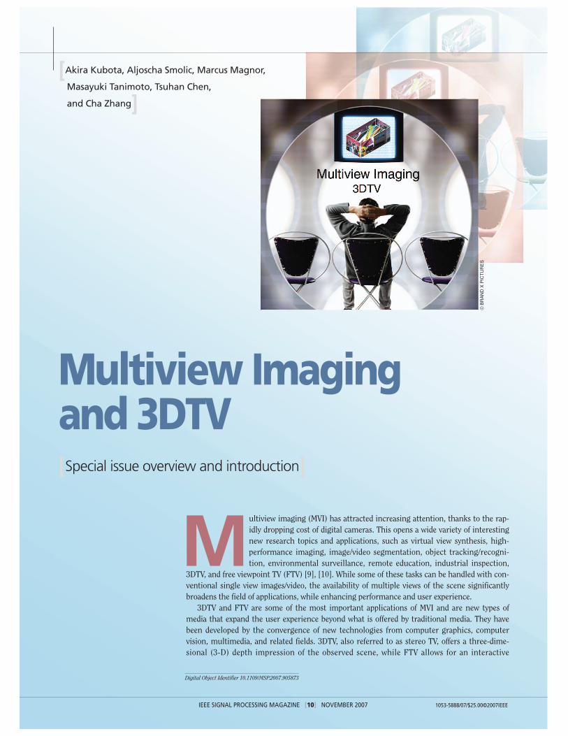
Multiview Imaging and 3DTV[Special issue overview and introduction]
[Akira Kubota, Aljoscha Smolic, Marcus Magnor,
Masayuki Tanimoto, Tsuhan Chen,
and Cha Zhang]
Digital Object Identifier 10.1109/MSP.2007.905873
IEEE SIGNAL PROCESSING MAGAZINE [10] NOVEMBER 2007 1053-5888/07/$25.00©2007IEEE
IEEE SIGNAL PROCESSING MAGAZINE [11] NOVEMBER 2007
selection of viewpoint and direction withina certain operating range. 3DTV and FTVare not mutually exclusive. On the con-trary, they can be very well combined with-in a single system as they are both basedon a suitable 3-D scene representation. Inother words, given a 3-D representation ofa scene, if a stereo pair of images corre-sponding to the human eyes can be ren-dered, the functionality of 3DTV isprovided. If a virtual view (i.e., not an actual camera view) corre-sponding to an arbitrary viewpoint and viewing direction can berendered, the functionality of FTV is provided.
As seen in the movie The Matrix, successive switching ofmultiple real images captured at different angles can give thesensation of a flying viewpoint. In a similar way, Eye Vision [11]realized a flying virtual camera for a scene in a Super Bowlgame. It used 33 cameras arranged around the stadium and con-trolled the camera directions mechanically to track the targetscene. In these systems, however, no new virtual images aregenerated, and the movement of the viewpoint is limited to thepredefined original camera positions; hence functionalities of3DTV/FTV are not provided. It is in fact extremely challenging torealize these functionalities using a small number of sparselypositioned cameras in a large 3-D space such as a stadium.
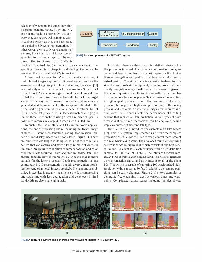
To enable the use of 3DTV and FTV in real-world applica-tions, the entire processing chain, including multiview imagecapture, 3-D scene representation, coding, transmission, ren-dering, and display, needs to be considered (Figure 1). Thereare numerous challenges in doing so. It is not easy to build asystem that can capture and store a large number of videos inreal time. An accurate calibration of camera position and colorproperty is also required. From acquired multiview data, oneshould consider how to represent a 3-D scene that is moresuitable for the latter processes. Depth reconstruction is onecentral task in 3-D representation but still a very difficult prob-lem for rendering novel images precisely. The amount of mul-tiview image data is usually huge, hence the data compressingand streaming with less degradation and delay over limitedbandwidth are also challenging tasks.
In addition, there are also strong interrelations between all ofthe processes involved. The camera configuration (array ordome) and density (number of cameras) impose practical limita-tions on navigation and quality of rendered views at a certainvirtual position. Therefore, there is a classical trade-off to con-sider between costs (for equipment, cameras, processors) andquality (navigation range, quality of virtual views). In general,the denser capturing of multiview images with a larger numberof cameras provides a more precise 3-D representation, resultingin higher quality views through the rendering and displayprocesses but requires a higher compression rate in the codingprocess, and vice versa. An interactive display that requires ran-dom access to 3-D data affects the performance of a codingscheme that is based on data prediction. Various types of quitediverse 3-D scene representations can be employed, whichimplies a number of different data types.
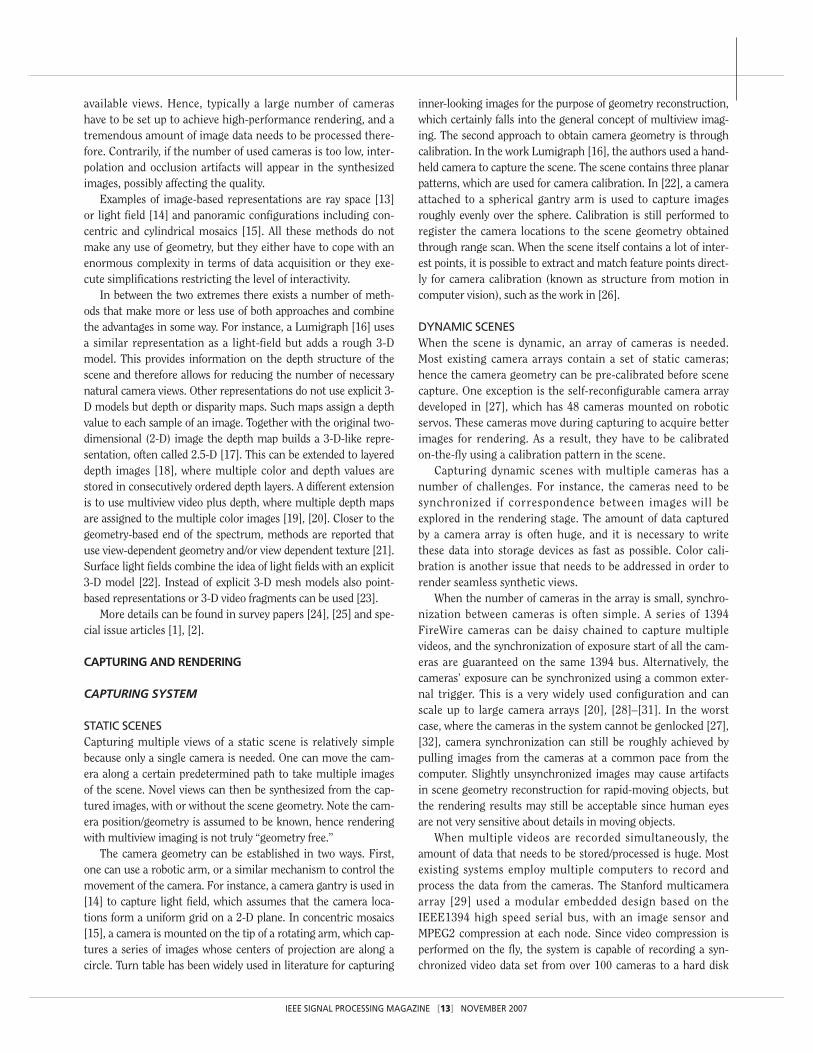
Here, let us briefly introduce one example of an FTV system[12]. This FTV system, implemented as a real-time completeprocessing chain, allows the user to freely control the viewpointof a real dynamic 3-D scene. The developed multiview capturingsystem is shown in Figure 2(a), which consists of one host-serv-er PC and 100 client PCs, each equipped with a high-definitioncamera (JAI PULNiX TM-1400CL). The interface between cam-era and PCs is created with Camera-Link. The host PC generatesa synchronization signal and distributes it to all of the clientPCs. This system is capable of capturing 100 synchronized high-resolution video signals at 30 fps. In addition, the camera posi-tions can be easily changed. Figure 2(b) shows examples ofgenerated free viewpoint images at various times and view-points. Complicated natural scenes including complex objects
[FIG1] Basic components of a 3DTV/FTV system.
MultiviewImage Capture
3-D Representation Coding
Transmission Rendering Display
3-D Scene
Its Replica!
[FIG2] A capturing system and generated free viewpoint images in FTV system [12].
(a) (b)

such as small moving fishes, bubbles, and reflection of lightfrom the aquarium glass are reproduced with high quality.
This special issue aims to provide a comprehensive overviewand tutorial of the basic concepts and recent developments of3DTV/FTV. We have selected eight articles in addition to thisintroductory article. Various challenging tasks involved in thecapturing, representation and rendering processes and theirstate-of-the-art technical solutions are broadly reviewed in“Image-Based Rendering and Synthesis” [1]. The following arti-cle, titled “Plenoptic Manifolds” [2], provides an overview ofimage-based representation and introduces a new 3-D represen-tation, Plenoptic Manifolds, based on analysis of structuralcoherence among multiview images. Model-based renderingapproaches are reviewed in “High Quality Reconstruction fromMultiview Video Streams” [3], where a sophisticated solution thatcan be applied to human actors for real-time rendering free-viewpoint video is described in detail. The next two articles focuson the compression process, “Compressing Time-Varying VisualContent” [4] broadly reviews coding techniques based on varioustypes of 3-D representation, and “Multiview Compression” [5]provides a review of multiview video compression based on spa-tial and temporal similarity between multiview video. Thestreaming process is addressed in the article “3DTV over IP” [6],where the emphasis is placed on a tutorial overview of streamingof multiview video over the Internet Protocol (IP) for various 3-Ddisplay clients. Finally, the last two articles focus on 3-D display.A sampling problem in 3-D display technique based on ray-spacerepresentation is addressed in “Resampling, Antialiasing, andCompression in Multiview 3-D Displays” [7]. The other article,titled “3-D Displays and Signal Processing” [8], provides a com-prehensive overview of various types of 3-D display.
3DTV/FTV is a state-of-the-art imaging system. In the past,image systems such as photography, film, and TV were distinctsystems. At present, they are being digitized more and more,allowing them to be handled on the same platform as pixel-basedsystems. These pixel-based systems are undergoing rapid devel-opment toward increasing the number of pixels. Although superhigh-definition TV has about 100 times the number of pixels ofstandard-definition TV, still only one view is used. In the future,the demand for more pixels will level off and will be replacedwith a demand for more views (i.e., more light rays in 3-D space).This is an evolution from pixel-based systems with a single imageto ray-based systems with multiview images. The technologiesfor light ray capturing and display are making rapid progress andhave created a huge opportunity for 3DTV/FTV to enter the con-sumer mass market in the near future. MVI will open the way toray-based image engineering that provides breakthrough tech-nologies to treat rays one by one.
In the following sections, this article provides the readerwith a brief introduction to the sequence of fundamental pro-cessing steps required for 3DTV and FTV: 3-D scene represen-tation, multiview image capturing and rendering, coding,and displaying of a 3-D scene. We hope that reading throughthese sections will aid the reader in understanding the arti-cles in this issue.
3-D SCENE REPRESENTATIONThe choice of a 3-D scene representation format is of centralimportance for the design of any 3DTV system. On one hand, thescene representation sets the requirements for multiview imagecapturing and processing. For instance using an image-basedrepresentation (see below) implies using a dense camera setting.A relatively sparse camera setting would only give poor renderingresults of virtual views. Using a geometry-based representation(see below) in contrary implies the need for sophisticated anderror prone image processing algorithms such as object segmen-tation and 3-D geometry reconstruction. On the other hand, the3-D scene representation determines the rendering algorithms(and with that also navigation range, quality, etc.), interactivity,as well as compression and transmission if necessary.
In computer graphics literature, methods for 3-D scene rep-resentation are often classified as a continuum in between twoextremes. The one extreme is represented by classical 3-D com-puter graphics. This approach can also be called geometry-basedmodeling. In most cases scene geometry is described on thebasis of 3-D meshes. Real world objects are reproduced usinggeometric 3-D surfaces with an associated texture mapped ontothem. More sophisticated attributes can be assigned as well. Forinstance, appearance properties (opacity, reflectance, specularlights, etc.) can significantly enhance the realism of the models.
Geometry-based modeling is used in applications such asgames, Internet, TV, and movies. The achievable performancewith these models might be excellent, typically if the scenes arepurely computer generated. The available technology for bothproduction and rendering has been highly optimized over thelast few years, especially in the case of common 3-D mesh repre-sentations. In addition, state-of-the-art PC graphics cards areable to render highly complex scenes with an impressive qualityin terms of refresh rate, levels of detail, spatial resolution, repro-duction of motion, and accuracy of textures.
A drawback of this approach is that typically high costs andhuman assistance are required for content creation. Aiming atphotorealism, 3-D scene and object modeling is often complexand time consuming, and it becomes even more complex ifdynamically changing scenes are considered. Furthermore, anautomatic 3-D object and scene reconstruction implies anestimation of camera geometry, depth structures, and 3-Dshapes. With some likelihood, all these estimation processesgenerate errors in the geometric model. These errors thenhave an impact on the rendered images. Therefore, high-qual-ity production of geometry model, e.g., for movies, is typicallydone user assisted.
The other extreme in 3-D scene representations is calledimage-based modeling and does not use any 3-D geometry atall. In this case virtual intermediate views are generated fromavailable natural camera views by interpolation. The mainadvantage is a potentially high quality of virtual view synthesisavoiding any 3-D scene reconstruction. However, this benefithas to be paid by dense sampling of the real world with a suffi-ciently large number of natural camera view images. Ingeneral, the synthesis quality increases with the number of
IEEE SIGNAL PROCESSING MAGAZINE [12] NOVEMBER 2007
IEEE SIGNAL PROCESSING MAGAZINE [13] NOVEMBER 2007
available views. Hence, typically a large number of camerashave to be set up to achieve high-performance rendering, and atremendous amount of image data needs to be processed there-fore. Contrarily, if the number of used cameras is too low, inter-polation and occlusion artifacts will appear in the synthesizedimages, possibly affecting the quality.
Examples of image-based representations are ray space [13]or light field [14] and panoramic configurations including con-centric and cylindrical mosaics [15]. All these methods do notmake any use of geometry, but they either have to cope with anenormous complexity in terms of data acquisition or they exe-cute simplifications restricting the level of interactivity.
In between the two extremes there exists a number of meth-ods that make more or less use of both approaches and combinethe advantages in some way. For instance, a Lumigraph [16] usesa similar representation as a light-field but adds a rough 3-Dmodel. This provides information on the depth structure of thescene and therefore allows for reducing the number of necessarynatural camera views. Other representations do not use explicit 3-D models but depth or disparity maps. Such maps assign a depthvalue to each sample of an image. Together with the original two-dimensional (2-D) image the depth map builds a 3-D-like repre-sentation, often called 2.5-D [17]. This can be extended to layereddepth images [18], where multiple color and depth values arestored in consecutively ordered depth layers. A different extensionis to use multiview video plus depth, where multiple depth mapsare assigned to the multiple color images [19], [20]. Closer to thegeometry-based end of the spectrum, methods are reported thatuse view-dependent geometry and/or view dependent texture [21].Surface light fields combine the idea of light fields with an explicit3-D model [22]. Instead of explicit 3-D mesh models also point-based representations or 3-D video fragments can be used [23].
More details can be found in survey papers [24], [25] and spe-cial issue articles [1], [2].
CAPTURING AND RENDERING
CAPTURING SYSTEM
STATIC SCENESCapturing multiple views of a static scene is relatively simplebecause only a single camera is needed. One can move the cam-era along a certain predetermined path to take multiple imagesof the scene. Novel views can then be synthesized from the cap-tured images, with or without the scene geometry. Note the cam-era position/geometry is assumed to be known, hence renderingwith multiview imaging is not truly “geometry free.”
The camera geometry can be established in two ways. First,one can use a robotic arm, or a similar mechanism to control themovement of the camera. For instance, a camera gantry is used in[14] to capture light field, which assumes that the camera loca-tions form a uniform grid on a 2-D plane. In concentric mosaics[15], a camera is mounted on the tip of a rotating arm, which cap-tures a series of images whose centers of projection are along acircle. Turn table has been widely used in literature for capturing
inner-looking images for the purpose of geometry reconstruction,which certainly falls into the general concept of multiview imag-ing. The second approach to obtain camera geometry is throughcalibration. In the work Lumigraph [16], the authors used a hand-held camera to capture the scene. The scene contains three planarpatterns, which are used for camera calibration. In [22], a cameraattached to a spherical gantry arm is used to capture imagesroughly evenly over the sphere. Calibration is still performed toregister the camera locations to the scene geometry obtainedthrough range scan. When the scene itself contains a lot of inter-est points, it is possible to extract and match feature points direct-ly for camera calibration (known as structure from motion incomputer vision), such as the work in [26].
DYNAMIC SCENESWhen the scene is dynamic, an array of cameras is needed.Most existing camera arrays contain a set of static cameras;hence the camera geometry can be pre-calibrated before scenecapture. One exception is the self-reconfigurable camera arraydeveloped in [27], which has 48 cameras mounted on roboticservos. These cameras move during capturing to acquire betterimages for rendering. As a result, they have to be calibratedon-the-fly using a calibration pattern in the scene.
Capturing dynamic scenes with multiple cameras has anumber of challenges. For instance, the cameras need to besynchronized if correspondence between images will beexplored in the rendering stage. The amount of data capturedby a camera array is often huge, and it is necessary to writethese data into storage devices as fast as possible. Color cali-bration is another issue that needs to be addressed in order torender seamless synthetic views.
When the number of cameras in the array is small, synchro-nization between cameras is often simple. A series of 1394FireWire cameras can be daisy chained to capture multiplevideos, and the synchronization of exposure start of all the cam-eras are guaranteed on the same 1394 bus. Alternatively, thecameras’ exposure can be synchronized using a common exter-nal trigger. This is a very widely used configuration and canscale up to large camera arrays [20], [28]–[31]. In the worstcase, where the cameras in the system cannot be genlocked [27],[32], camera synchronization can still be roughly achieved bypulling images from the cameras at a common pace from thecomputer. Slightly unsynchronized images may cause artifactsin scene geometry reconstruction for rapid-moving objects, butthe rendering results may still be acceptable since human eyesare not very sensitive about details in moving objects.
When multiple videos are recorded simultaneously, theamount of data that needs to be stored/processed is huge. Mostexisting systems employ multiple computers to record andprocess the data from the cameras. The Stanford multicameraarray [29] used a modular embedded design based on theIEEE1394 high speed serial bus, with an image sensor andMPEG2 compression at each node. Since video compression isperformed on the fly, the system is capable of recording a syn-chronized video data set from over 100 cameras to a hard disk

array using as few as one PC per 50 image sensors. The work in[32] introduced an interesting concept called distributed lightfield camera. Multiple computers are used to serve the data tothe renderer upon request. Ideally, these computers can be inte-grated with the cameras, so that each camera can serve a fewrandom light rays (pixels) when they are needed for rendering.This design minimizes the bandwidth required between thecameras and renderers, which is critical when hundreds of cam-eras are employed.
For low-cost camera arrays, it is difficult to guarantee that allcameras have the same color when capturing the same object.Color inconsistency across cameras may cause incorrect view-dependent color variation during rendering. The color calibra-tion issue was rarely studied in literature. In [33], Joshi et al.proposed an iterative scheme to calibrate the sensors to matcheach other rather than a common standard. This yields bettercolor consistency between cameras, which is more suitable formultiview imaging applications.
SCENE GEOMETRYThe geometry of the scene is usually very useful during the ren-dering of 3DTV or FTV. In this section we briefly review a fewmechanisms that can be used to obtain the scene geometrydirectly instead of deriving from images.
One well-known depth discovery technique is based on trian-gulation. A laser stripe is scanned across the scene, which is cap-tured by a camera positioned at a distance from the laser pointer.The range of the scene is then determined by the focal length ofthe camera, the distance between the camera and the laser point-er, and the observed stripe position in the captured image. Due to
the limited sweeping speed of the stripe lights, this method isoften used to capture the geometry of static scenes. Recentimprovements in the triangulation method can use multiplestripe patterns to recover scene depth with one single image.However, its application in 3DTV or FTV is still limited becausethe stripe pattern may change the scene color/texture whenimages are simultaneously captured for rendering.
For dynamic scenes, most commercially available 3-D cam-eras are based on the time-of-flight principle. Laser beams(often in the infrared spectrum) are emitted to the scene, andthe reflections are collected by the device to measure the timeof flight. Broadly speaking, time-of-flight range sensors can bedivided into two main categories: pulsed wave and continuousmodulated wave. Pulsed-wave sensors measure the time ofdelay directly, while continuous modulated-wave sensorsmeasure the phase shift between the emitted and receivedlaser beams to determine the scene depth. One example ofpulsed wave sensors is the 3-D terrestrial laser scanner sys-tems manufactured by Riegl (http://www.riegl.com/).Continuous modulated wave sensors include SwissRanger(http://www.swissranger.ch/) and ZCam Depth Camera from3DV Systems (http://www.3dvsystems.com/).
IMAGE-BASED RENDERING
LIGHT FIELD REPRESENTATION AND RENDERINGImagine that it is possible to record all light rays traveling from anobject’s surface to arbitrary observer positions. In this case, wecould create correct novel views from various perspectives simplyby selecting the necessary light rays from the recorded rays. This is
obvious; however this concept has brought us a new para-digm, called image-based rendering (IBR), and IBRresearch has attracted much attention since the early1990s. The main reason is that it allows photo-realisticrendering with a much lighter computation load, inde-pendent of the scene complexity. The history of this con-cept is briefly described in [34].
The plenoptic function [35] was introduced to describethese light rays in seven dimensions (7-D), using theparameters of 3-D position, 2-D direction, wave-length(color) and time. Consider the case of fixed color compo-nent and time, it reduces to a five-dimensional function.Furthermore, since it can be assumed that light intensityremains constant along its trajectory, an arbitrary light raycan be described with a 4-D plenoptic function. This repre-sentation of light rays is called ray space [13] or light field[14], which is the most useful and practical representa-tion. The light field is usually acquired with a 2-D planerarray of cameras (Figure 3). In this case, each light ray canbe parameterized by the 2-D camera position and the 2-Dpixel position. If we have light field data densely sampledon a plane, we can generate a novel view correctly byselecting (resampling) the necessary light rays. Variousdimensionally reduced versions of the plenoptic functionhave been surveyed in [24], [25], and [2].[FIG3] Light field capturing and rendering.
Dense Camera Array
Novel Observer Position(Novel View)Captured Light Rays
(4-D Plenoptic Functions)
Selected Light Rays
Omitted Light Raysfrom the Object Surface
Object
IEEE SIGNAL PROCESSING MAGAZINE [14] NOVEMBER 2007
We can consider this capturing problem in IBR as a samplingproblem of the plenoptic function for the object. The goal is tosample the plenoptic function densely enough to reconstruct theoriginal continuous plenoptic function through resampling thesampled function. Sampling theory provides us with an answeras to how densely we need to capture the light field. Shum et al.[36] applied this theory to the light field and theoretically derivedthe minimum camera spacing density and the interpolation fil-ter. Although it has been possible to build a camera array systemwith more than 100 cameras, it is unfortunately impossible tospace cameras densely enough for most practical applications,due to camera size. Instead of using multiple cameras, it is alsopossible to acquire a much denser light field through the use ofan array of micro lenses and a single camera; however the rangeof viewing positions and directions is much more limited. It ispossible to acquire light fields densely and correctly for staticscenes by moving a hand-held video camera, however the cameraposition must be precisely obtained.
VIEW INTERPOLATION FROMSPARSELY SAMPLED LIGHT FIELDAs mentioned above, equipment is not yet developed for practi-cal applications that can acquire light fields or the plenopticfunction with the required density. For novel view generationusing light fields sampled with insufficient density, we need tointerpolate the missing light rays. The intensity of the desiredmissing ray is computed by blending a small number (typicallyfour) of acquired rays. Here, we take the average (i.e., the meanvalue) of the acquired rays in the blending process. The problemis that of which rays should be used for this average. If the depthof the missing ray is known, then we can easilyselect and use the rays corresponding to this depth.Hence, we need to estimate the depth beforehand.
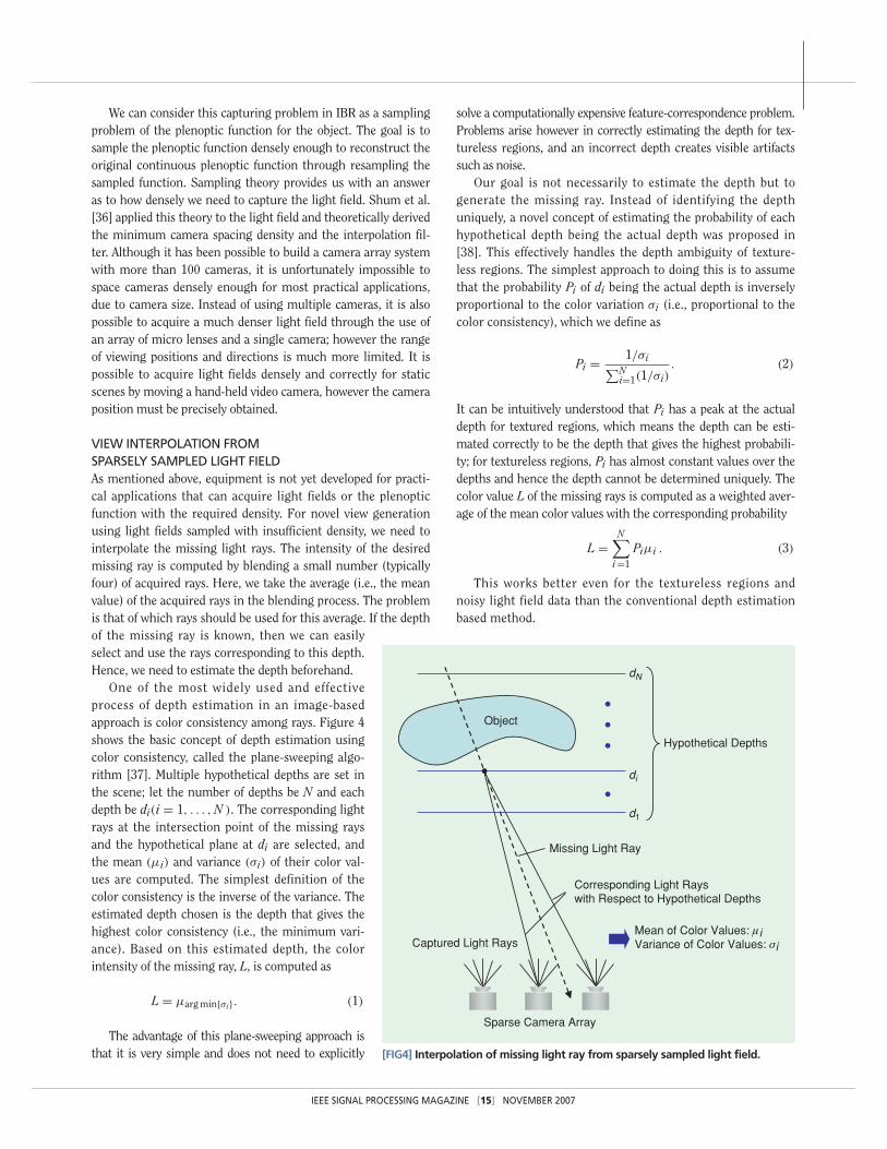
One of the most widely used and effectiveprocess of depth estimation in an image-basedapproach is color consistency among rays. Figure 4shows the basic concept of depth estimation usingcolor consistency, called the plane-sweeping algo-rithm [37]. Multiple hypothetical depths are set inthe scene; let the number of depths be N and eachdepth be di(i = 1, . . . , N ). The corresponding lightrays at the intersection point of the missing raysand the hypothetical plane at di are selected, andthe mean (μi) and variance (σi) of their color val-ues are computed. The simplest definition of thecolor consistency is the inverse of the variance. Theestimated depth chosen is the depth that gives thehighest color consistency (i.e., the minimum vari-ance). Based on this estimated depth, the colorintensity of the missing ray, L, is computed as
L = μarg min{σi}. (1)
The advantage of this plane-sweeping approach isthat it is very simple and does not need to explicitly
solve a computationally expensive feature-correspondence problem.Problems arise however in correctly estimating the depth for tex-tureless regions, and an incorrect depth creates visible artifactssuch as noise.
Our goal is not necessarily to estimate the depth but togenerate the missing ray. Instead of identifying the depthuniquely, a novel concept of estimating the probability of eachhypothetical depth being the actual depth was proposed in[38]. This effectively handles the depth ambiguity of texture-less regions. The simplest approach to doing this is to assumethat the probability Pi of di being the actual depth is inverselyproportional to the color variation σi (i.e., proportional to thecolor consistency), which we define as
Pi = 1/σi∑Ni=1(1/σi)
. (2)
It can be intuitively understood that Pi has a peak at the actualdepth for textured regions, which means the depth can be esti-mated correctly to be the depth that gives the highest probabili-ty; for textureless regions, Pi has almost constant values over thedepths and hence the depth cannot be determined uniquely. Thecolor value L of the missing rays is computed as a weighted aver-age of the mean color values with the corresponding probability
L =N∑
i =1
Piμi . (3)
This works better even for the textureless regions andnoisy light field data than the conventional depth estimationbased method.
[FIG4] Interpolation of missing light ray from sparsely sampled light field.
Mean of Color Values: μi Variance of Color Values: σi
Sparse Camera Array
Captured Light Rays
Missing Light Ray
Hypothetical Depths
Object
Corresponding Light Rayswith Respect to Hypothetical Depths
d1
di
dN
IEEE SIGNAL PROCESSING MAGAZINE [15] NOVEMBER 2007

The above method, using Pi as a coefficient, fuses color meanvalues μi into the missing color value L. Since Pi depends uponthe scene and needs to be computed for every frame for dynamicscenes. A different fusion method was presented in [39] thatdoes not need to estimate any scene information, although itrequires a denser camera arrangement than the depth-probabili-ty method above. Assuming texture si exists on each hypotheti-cal plane, this method models the missing color value L as thesum of the textures
L =N∑
i =1
si. (4)
The mean color value μi is modeled as a linear combination ofthe assumed textures with blending artifacts:
⎧⎪⎪⎪⎪⎪⎪⎪⎪⎪⎨⎪⎪⎪⎪⎪⎪⎪⎪⎪⎩
μ1 = s1 + h12(s2) + h13(s3)
+ · · · + h1N(sN)
μ2 = h21(s1) + s2 + h23(s3)
+ · · · + h2N(sN)...
μN = hN1(s1) + · · ·+ hNN−1(sN−1) + sN.
(5)
The function hij(·) denotes a point spread function (PSF)that causes blending artifacts on the j th texturessj( j = 1, 2, . . . , N ). All PSFs are spatially varying filters but canbe simply determined in such a way that we assume a point lightsource at depth dj and compute the mean value μi on differentdepth di. The resulting mean value is the filter hij(·). This com-putation can be done beforehand, independent of the scene. Thissimultaneous equation for the textures is iteratively solvedusing the Gauss-Seidel method starting from arbitrary initialsolutions. Solving this simultaneous equation is ill conditionedand scene textures cannot be obtained correctly; the obtainedeach texture contains blurry textures that are supposed to existat other depths. The sum of these solutions however provides agood approximation to the missing ray L.
These image-fusion approaches are effective for scenesthat consist of a nonoccluded surface possessing theLambertian property (reflected light intensity is constant forevery direction). Various IBR approaches for general scenesis reviewed in [1].
MODEL-BASED RENDERING
MODEL-BASED FTV ACQUISITIONIn many FTV scenarios, the object that is being recorded isknown in advance. Suitably implemented, such a priori know-ledge can be used to bias the scene reconstruction outcometowards plausible results only. Of course, a suitable model ofthe recorded object(s) must be available. A model also enablesenforcing low-level as well as high-level constraints about theobject’s motion, from temporally coherent movement to anato-
my-consistent motion. Another advantage of model-based FTVis that a priori model geometry can be highly detailed, whichfacilitates high-quality rendering results and circumvents ren-dering inaccuracies due to poorly resolved geometry. In gener-al, model-based FTV methods are able to achieve more robustand authentic rendering results than methods ignorant ofrecorded scene content.
While for motion capture purposes, it is sufficient to recovermodel animation parameters, FTV imposes the additionaldemand that the resulting model must be able to produce con-vincing rendering results. The challenge in model-based FTVtherefore is how to automatically, robustly, and visually consis-tently match a parameterized 3-D geometry model to recordedimage content.
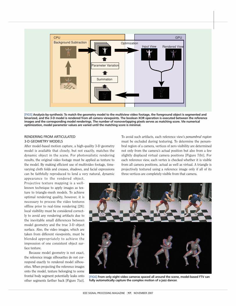
One model-based FTV method that is suitable for synchro-nized multiview video footage consists of matching model toobject silhouettes based on an analysis-by-synthesis approach[28], as shown in Figure 5. The object’s silhouettes, as seenfrom the different camera viewpoints, are used to match themodel to the recorded video images: The foreground in allvideo images is segmented and binarized. At the same time,the 3-D object model is rendered from all camera viewpointsusing conventional graphic hardware, after which the ren-dered images are thresholded to yield binary masks of themodel’s silhouettes. Then, the rendered model silhouettes arecompared to the corresponding image silhouettes: as compar-ison measure, or matching score, the number of silhouettepixels is used that do not overlap when putting the renderedsilhouette on top of the recorded silhouette. Conveniently, thelogical exclusive-or (XOR) operation between the renderedimage and the recorded image yields those silhouette pixelsthat are not overlapping. By summing over the nonoverlap-ping pixels for all images, the matching score is obtained.This matching score can be evaluated very efficiently on con-temporary graphics hardware. To adapt model parameter val-ues such that the matching score becomes minimal, astandard numerical nonlinear optimization algorithm, e.g.the Powell optimization method [40], runs on the CPU. Foreach new set of model parameter values, the optimizationroutine evokes the matching score evaluation routine on thegraphics card which can be evaluated many hundred timesper second. After convergence, object texture can be addition-ally exploited for pose refinement [41].
One advantage of model-based analysis is the low-dimension-al parameter space when compared to general reconstructionmethods (Figure 6): The parameterized 3-D model may provideonly a few dozen degrees of freedom that need to be determined,which greatly reduces the number of potential local minima.Many high-level constraints are already implicitly incorporatedinto the model, such as kinematic capabilities. Additional con-straints can be easily enforced by making sure that all parametervalues stay within their anatomically plausible range duringoptimization. Finally, temporal coherence is straightforwardlymaintained by allowing only some maximal rate of change inparameter value from one time step to the next.
IEEE SIGNAL PROCESSING MAGAZINE [16] NOVEMBER 2007
RENDERING FROM ARTICULATED 3-D GEOMETRY MODELSAfter model-based motion capture, a high-quality 3-D geometrymodel is available that closely, but not exactly, matches thedynamic object in the scene. For photorealistic renderingresults, the original video footage must be applied as texture tothe model. By making efficient use of multivideo footage, time-varying cloth folds and creases, shadows, and facial expressionscan be faithfully reproduced to lend a very natural, dynamicappearance to the rendered object.Projective texture mapping is a well-known technique to apply images as tex-ture to triangle-mesh models. To achieveoptimal rendering quality, however, it isnecessary to process the video texturesoffline prior to real-time rendering [28]:local visibility must be considered correct-ly to avoid any rendering artifacts due tothe inevitable small differences betweenmodel geometry and the true 3-D objectsurface. Also, the video images, which aretaken from different viewpoints, must beblended appropriately to achieve theimpression of one consistent object sur-face texture.
Because model geometry is not exact,the reference image silhouettes do not cor-respond exactly to rendered model silhou-ettes. When projecting the reference imagesonto the model, texture belonging to somefrontal body segment potentially leaks ontoother segments farther back [Figure 7(a)].
To avoid such artifacts, each reference view’s penumbral regionmust be excluded during texturing. To determine the penum-bral region of a camera, vertices of zero visibility are determinednot only from the camera’s actual position but also from a fewslightly displaced virtual camera positions [Figure 7(b)]. Foreach reference view, each vertex is checked whether it is visiblefrom all camera positions, actual as well as virtual. A triangle isprojectively textured using a reference image only if all of itsthree vertices are completely visible from that camera.
[FIG6] From only eight video cameras spaced all around the scene, model-based FTV canfully automatically capture the complex motion of a jazz dancer.
[FIG5] Analysis-by-synthesis: To match the geometry model to the multiview video footage, the foreground object is segmented andbinarized, and the 3-D model is rendered from all camera viewpoints. The boolean XOR operation is executed between the referenceimages and the corresponding model renderings. The number of nonoverlapping pixels serves as matching score. VIe numericaloptimization, model parameter values are varied until the matching score is minimal.
CPU
Background Subtraction
Parameter Variation
Summation
OptimizationInput View Rendered View
GPU
IEEE SIGNAL PROCESSING MAGAZINE [17] NOVEMBER 2007

Most surface areas of the model are seen from more than onecamera. If the model geometry corresponded exactly to that ofthe recorded object, all camera views could be weighted accord-ing to their proximity to the desired viewing direction andblended without loss of detail. However, model geometry hasbeen adapted to the recorded person by optimizing only a com-paratively small number of free parameters. The model is alsocomposed of rigid body elements which is clearly an approxima-tion whose validity varies, e.g., with the person’s apparel. Insummary, the available model surface can be expected to locallydeviate from true object geometry. Accordingly, projectively tex-turing the model by simply blending multiple reference imagescauses blurred rendering results, and model texture varies dis-continuously when the viewpoint is moving. Instead, by takinginto account triangle orientation with respect to camera direc-tion, high-quality rendering results can still be obtained for pre-dominantly diffuse surfaces [28].
After uploading the 3-D model mesh and video cameras’ pro-jection matrices to the graphics card, the animated model is readyto be interactively rendered. During rendering, the multiviewimagery, predetermined model pose parameter values, visibilityinformation, and blending coefficients must be continuously
uploaded, while the view-dependent texture weights are comput-ed on the fly on the GPU. Easily achieving real-time renderingframe rates, views of the object from arbitrary perspective are pos-sible, as well as freeze-and-rotate shots, fly-around sequences,close-ups, slow motion, fast forward, or reverse play (Figure 8).More detail can be given in [3] in this issue.
CODINGThree-dimensional scene representation formats integrate vari-ous types of data, such as multiview video, and geometry data inform of depth or 3-D meshes. In general, these results in atremendous amount of data that needs to be transmitted orstored. Therefore, efficient compression is a key condition forthe success of such applications. Further, the availability of openinternational standards is in general an important enabling fac-tor for the development of markets in the media business.ISO/IEC JTC 1/SC 29/WG 11 (Moving Picture Experts Group—MPEG) is one of the international standardization bodies thatplay an important role in digital media standardization [42].
The compression of 3-D data has recently received a lot ofattention in research and development. Technology has reacheda good level of maturation, however, since the field is still very
young compared for instance to classical2-D video coding, there is still a lot ofroom for improvement and optimization.The area of 3-D compression may be cate-gorized into 3-D meshes and pixel-typedata, such as multiview images, video anddepth or disparity. Associated data such asexternal and internal camera parametersdefining the 3-D space and 2-D–3-D rela-tions need to be considered in addition.
Three-dimensional mesh compressioncan be divided into static and dynamic.Static 3-D mesh compression has beenstudied extensively. Efficient algorithmsare available; some providing extendedfunctionality such as progressive decoding.Dynamic 3-D meshes describe movingobjects and change over time. This is more
interesting for multiview video and 3DTV applica-tions as studied in this special issue. Thisresearch area has gained significant attentionrecently and various algorithms have been pro-posed. More details can be found in [43] and [4].
Multiview video coding (MVC) has also gainedsignificant attention recently. Numerous papershave been published and significant progress hasbeen made. Multiview video shows the same 3-Dscene from different viewpoint, resulting in atremendous amount of raw video data. However,the different camera signals contain a largeamount of statistical dependencies. The key forefficient MVC lies in exploitation of these inter-view redundancies in addition to temporal
[FIG8] Model-based FTV: The user can freely move around the dynamic object at real-time rendering frame rates.
[FIG7] Penumbral region determination: (a) Small differences between object silhouetteand model outline can cause texture of frontal model segments to leak onto segmentsfarther back. (b) By projecting each reference image onto the model also from slightlydisplaced camera positions, regions of dubious visibility are determined. These areexcluded from texturing by the respective reference image. ((a) reprinted from [28]©2003 ACM).
(a) (b)
IEEE SIGNAL PROCESSING MAGAZINE [18] NOVEMBER 2007
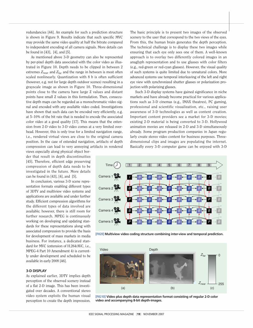
redundancies [44]. An example for such a prediction structureis shown in Figure 9. Results indicate that such specific MVCmay provide the same video quality at half the bitrate comparedto independent encoding of all camera signals. More details canbe found in [43], [4], and [5].
As mentioned above 3-D geometry can also be representedby per-pixel depth data associated with the color video as illus-trated in Figure 10. Depth needs to be clipped in between 2extremes Znear and Zfar and the range in between is most oftenscaled nonlinearly. Quantization with 8 b is often sufficient(however, e.g. not for large depth outdoor scenes) resulting in agrayscale image as shown in Figure 10. Three-dimensionalpoints close to the camera have large Z values and distantpoints have small Z values in this formulation. Then, consecu-tive depth maps can be regarded as a monochromatic video sig-nal and encoded with any available video coded. Investigationshave shown that such data can be encoded very efficiently, e.g.at 5–10% of the bit rate that is needed to encode the associatedcolor video at a good quality [17]. This means that the exten-sion from 2-D video to 3-D video comes at a very limited over-head. However, this is only true for a limited navigation range,i.e., rendered virtual views are close to the original cameraposition. In the case of extended navigation, artifacts of depthcompression can lead to very annoying artifacts in renderedviews especially along physical object bor-der that result in depth discontinuities[45]. Therefore, efficient edge preservingcompression of depth data needs to beinvestigated in the future. More detailscan be found in [43], [4], and [5].
In conclusion, various 3-D scene repre-sentation formats enabling different typesof 3DTV and multiview video systems andapplications are available and under furtherstudy. Efficient compression algorithms forthe different types of data involved areavailable; however, there is still room forfurther research. MPEG is continuouslyworking on developing and updating stan-dards for these representations along withassociated compression to provide the basisfor development of mass markets in mediabusiness. For instance, a dedicated stan-dard for MVC (extension of H.264/AVC, i.e.,MPEG-4 Part 10 Amendment 4) is current-ly under development and scheduled to beavailable in early 2008 [46].
3-D DISPLAYAs explained earlier, 3DTV implies depthperception of the observed scenery insteadof a flat 2-D image. This has been investi-gated over decades. A conventional stereovideo system exploits the human visualperception to create the depth impression.
The basic principle is to present two images of the observedscenery to the user that correspond to the two views of the eyes.From this, the human brain generates the depth perception.The technical challenge is to display these two images whileensuring that each eye only sees one of them. A well-knownapproach is to overlay two differently colored images in ananaglyph representation and to use glasses with color filters(e.g., red-green or red-cyan glasses). However, the visual qualityof such systems is quite limited due to unnatural colors. Moreadvanced systems use temporal interleaving of the left and righteye view with synchronized shutter glasses or polarization pro-jection with polarizing glasses.
Such 3-D display systems have gained significance in nichemarkets and have already become practical for various applica-tions such as 3-D cinemas (e.g., IMAX theatres), PC gaming,professional and scientific visualization, etc., raising userawareness of 3-D technologies as well as content creation.Important content providers see a market for 3-D movies;existing 2-D material is being converted to 3-D. Hollywoodanimation movies are released in 2-D and 3-D simultaneouslyalready. Some program production companies in Japan regu-larly create stereo video content for business purposes. Three-dimensional clips and images are populating the internet.Basically every 3-D computer game can be enjoyed with 3-D
[FIG9] Multiview video coding structure combining inter-view and temporal prediction.
1 2 3 4 5 6 7 8 9
Camera 1
Time
Camera 2
Camera 3
Camera 4
Camera 5
I B B B B B B B I B
B B B B B B B B B
P
B B B B B B B B B
P B B B B B B B P B
B
B B B B B B B P B
B
[FIG10] Video plus depth data representation format consisting of regular 2-D colorvideo and accompanying 8-bit depth-images.
0
255
Zfar
Znear
Video
(a) (b) (c)
Depth
IEEE SIGNAL PROCESSING MAGAZINE [19] NOVEMBER 2007
perception with very limited hardware costs to upgrade anycommon end-user PC.
However, conventional stereo video systems require wearingspecific glasses, which is among other reasons considered to bethe main obstacle for development of wide 3DTV user markets.A living room environment requires new concepts for 3-D dis-plays, for watching TV with family and friends. So-called auto-stereoscopic displays may overcome this situation in the verynear future. Such displays provide 3-D depth perception with-out the necessity of wearing glasses. Technology is based onlenticular screens or parallax barrier systems and is alreadyquite advanced. Displays are on the market, so far mainly forprofessional customers, but some manufacturers plan introduc-ing them to broad end-user markets in the near future.Backward compatible concepts for introduction of 3DTV viabroadcast or DVD are developed.
The multiview display principle has been used to constructauto-stereoscopic displays. With this approach, parallax images,which are perspective projections of three-dimensional objects,are displayed to converge to the corresponding view points.Signal processing for multiview 3-D displays is reviewed in thespecial issue paper [7].
More recently, the directional display technique has come tobe used. With this technique, directional images, which areorthographic projections of objects, are displayed with nearlyparallel rays [47]. The directional display technique providesmore natural motion parallax than the multiview technique.The 3-D impression becomes free from the visual fatigue effectcaused by the accommodation-convergence conflict.
However, these systems still rely on a fake of the humanvisual system. Real 3-D images can be generated by even moreadvanced approaches such as volumetric or holographic dis-plays, which will most probably provide us with real 3-D sensa-tion in the mid term future. So far such systems are underdevelopment and not yet mature enough. A detailed overview of3-D display technology can be found in [8].
ACKNOWLEDGEMENTThis issue attracted much attention from many researchers invarious fields, and we received more than 60 paper proposals.Due to limited schedule and allocated pages for such a largenumber of submissions, we had to select papers within a shorttime. We would like to thank all of authors who submitted theirproposal to this special issue and to express many thanks to allthe reviewers as well. We also express thanks to Prof. Douglas BWilliams, Special Sections area editor, for his great support andhelp. We would further like to thank the Interactive VisualMedia Group of Microsoft Research for providing theBreakdancers data sets used in Figure 10.
GUEST EDITORSAkira Kubota received the B.E. degree in electrical engineer-ing from Oita University, Japan, in 1997, the M.E. and Dr.E.degrees in electrical engineering from the University ofTokyo, Japan, in 1999 and 2002, respectively. He is an assis-
tant professor at the Department of Information Processingat Tokyo Institute of Technology, Yokohama, Japan. FromSeptember 2003 to July 2004, he was with the AdvancedMultimedia Processing Laboratory at Carnegie MellonUniversity as a research associate. His research interestsinclude image-based rendering and visual reconstruction.
Aljoscha Smolic received the Dr.-Ing. degree from AachenUniversity of Technology in 2001. Since 1994 he has beenwith Fraunhofer HHI, Berlin, Germany. He conductedresearch in various fields of video processing, video coding,computer vision and computer graphics. He is an adjunct pro-fessor at the Technical University of Berlin. He is an area edi-tor for Signal Processing: Image Communication and guesteditor for IEEE Transactions on Circuits and Systems forVideo Technology and IEEE Signal Processing Magazine. Hechaired the MPEG ad hoc group on 3DAV pioneering stan-dards for 3-D video. Currently he is editor of the MultiviewVideo Coding (MVC) standard.
Marcus Magnor heads the Computer Graphics Lab of thecomputer science department at the Technical UniversityBraunschweig. He received his B.A. (1995) and M.S. (1997) inphysics from the Wurzburg University and the University of NewMexico, respectively, and his Ph.D. (2000) in electrical engineer-ing from Erlangen University. His research interests include thecomplete visual information processing pipeline, from imageformation, acquisition, and analysis to view synthesis, percep-tion, and cognition.
Masayuki Tanimoto received B.E., M.E. and Dr.E. degreesin electronic engineering from the University of Tokyo in 1970,1972, and 1976, respectively. Since 1991, he has been a profes-sor at the Graduate School of Engineering, Nagoya University.He was vice president of ITE, chairperson of Technical Groupon Communication Systems of IEICE, chairperson of thesteering committee of Picture Coding Symposium of Japan,IEICE councilor, ITE councilor, and Tokai Section chair ofIEICE. He received IEICE Fellow Award, IEICE AchievementAward, ITE Fellow Award and Commendation for Science andTechnology by the Minister of Education, Culture, Sports,Science, and Technology.
Tsuhan Chen received the B.S. degree in electrical engi-neering from the National Taiwan University in 1987, and theM.S. and Ph.D. degrees in electrical engineering from theCalifornia Institute of Technology, Pasadena, California, in1990 and 1993, respectively. He has been with the Departmentof Electrical and Computer Engineering, Carnegie MellonUniversity, Pittsburgh, Pennsylvania, since October 1997,where he is currently a professor. He directs the AdvancedMultimedia Processing Laboratory. He helped create theTechnical Committee on Multimedia Signal Processing, as thefounding chair, and the Multimedia Signal ProcessingWorkshop. His endeavor later evolved into founding of theIEEE Transactions on Multimedia and the IEEE InternationalConference on Multimedia and Expo. He was editor-in-chieffor IEEE Transactions on Multimedia for 2002–2004. He is aFellow of the IEEE.
IEEE SIGNAL PROCESSING MAGAZINE [20] NOVEMBER 2007

AUTHORCha Zhang received his B.S. and M.S. degrees from TsinghuaUniversity, Beijing, China in 1998 and 2000, respectively, both inelectronic engineering, and the Ph.D. degree in electrical andcomputer engineering from Carnegie Mellon University, in 2004.Since 2004, he has been a researcher with Microsoft Research.His current research focuses on automated lecture rooms,audio/video processing for multimedia collaboration, computervision, etc. He has also worked on image-based rendering (com-pression/sampling/rendering), 3-D model retrieval, active learn-ing, and peer-to-peer networking.
REFERENCES[1] S.C. Chan, H.Y. Shum, and K.T. Ng, “Image-based rendering and synthesis,”IEEE Signal Processing Mag. vol. 24, no. 7, pp. 22–33, Nov. 2007.
[2] J. Berent and P. Luigi Dragotti, “Plenoptic manifolds,” IEEE Signal ProcessingMag., vol. 24, no. 7, pp. 34–44, Nov. 2007.
[3] C. Theobalt, N. Ahmed, G. Ziegler, and H.-P. Seidel, “High-quality reconstruc-tion from multiview video streams,” IEEE Signal Processing Mag., vol. 24, no. 7,pp. 45–57, Nov. 2007.
[4] K. Müller, P. Merkle, and T. Wiegand, “Compressing time-varying visual con-tent,” IEEE Signal Processing Mag., vol. 24, no. 7, pp. 58–67, Nov. 2007.
[5] M. Flierl and B. Girod, “Multiview video compression,” IEEE Signal ProcessingMag., vol. 24, no. 7, pp. 66–76, Nov. 2007.
[6] A. Murat Tekalp, E. Kurutepe, and M. Reha Civanlar, “3DTV over IP,” IEEESignal Processing Mag., vol. 24, no. 7, pp. 77–87, Nov. 2007.
[7] M. Zwicker, A. Vetro, S. Yea, W. Matusik, H. Pfister “Resampling, antialiasing,and compression in multiview 3-D displays,” IEEE Signal Processing Mag., vol. 24,no. 7, pp. 88–96, Nov. 2007.
[8] J. Konrad and M. Halle, “3-D displays and signal processing,” IEEE SignalProcessing Mag., vol. 24, no. 7, pp. 97–111, Nov. 2007.
[9] M. Tanimoto, “Free viewpoint television,” J. Three Dimensional Images, vol.15, no. 3, pp. 17–22, Sept. 2001 (in Japanese).
[10] M. Tanimoto, “Free viewpoint television—FTV,” in Proc. Picture CodingSymp. 2004, Dec. 2004.
[11] CBS Broadcasting Inc., http://www.cbs.com/.
[12] M. Tanimoto, “Overview of free viewpoint Television,” Signal Process. ImageCommun., vol. 21, no. 6, pp. 454–461, July 2006.
[13] T. Fujii, T. Kimoto, and M. Tanimoto, “Ray space coding for 3D visual commu-nication,” Picture Coding Symp. 1996, Mar. 1996, pp. 447–451.
[14] M. Levoy and P. Hanrahan, “Light field rendering,” in Proc. ACM SIGGRAPH,Aug. 1996, pp. 31–42.
[15] H.Y. Shum and L.W. He, “Rendering with concentric mosaics,” in Proc. ACMSIGGRAPH, Aug. 1999, pp. 299–306.
[16] S.J. Gortler, R. Grzesczuk, R. Szeliski, and M.F. Cohen, “The Lumigraph,”in Proc. ACM SIGGRAPH’96, Aug. 1996, pp. 43–54.
[17] C. Fehn, P. Kauff, M. Op de Beeck, F. Ernst, W. Ijsselsteijn, M. Pollefeys, L.Vangool, E. Ofek, and I. Sexton, “An evolutionary and optimised approach on 3D-TV,” IBC 2002, Int. Broadcast Convention, Amsterdam, Netherlands, Sept. 2002.
[18] J. Shade, S. Gortler, L.W. He, and R. Szeliski, “Layered Depth Images,” inProc. SIGGRAPH’98, Orlando, FL, July 1998.
[19] P. Kauff, N. Atzpadin, C. Fehn, M. Müller, O. Schreer, A. Smolic, and R. Tanger,“Depth map creation and image based rendering for advanced 3DTV services pro-viding interoperability and scalability,” Signal Process. Image Commun., SpecialIssue on 3DTV, Feb. 2007.
[20] C.L. Zitnick, S.B. Kang, M. Uyttendaele, S. Winder, and R. Szeliski, “High-quality video view interpolation using a layered representation,” in Proc. ACM SIG-GRAPH and ACM Trans. Graphics, Los Angeles, CA, Aug. 2004.
[21] P. Debevec, C. Taylor, and J. Malik, “Modeling and rendering architecture fromphotographs: A hybrid geometry- and image-based approach,” in Proc. SIGGRAPH1996, 1996, pp. 11–20.
[22] D. Wood, D. Azuma, W. Aldinger, B. Curless, T. Duchamp, D. Salesin, and W.Stuetzle, “Surface Light Fields for 3D Photography,” in Proc. SIGGRAPH 2000.
[23] S. Wurmlin, E. Lamboray, and M. Gross, “3D video fragments: Dynamic pointsamples for real-time free-viewpoint video,” Comput. Graph., (Special issue oncoding, compression and streaming techniques for 3D and multimedia data), vol.28, no. 1, pp. 3–14, 2004.
[24] H.-Y. Shum, S.B. He, and S.-C. Chan, “Survey of image-based representationsand compression techniques,” IEEE Trans. Circuits Syst. Video Technol., vol. 13,no. 11, pp. 1020–1037, 2003.
[25] C. Zhang and T. Chen, “A survey on image-based rendering—Representation,sampling and compression,” EURASIP Signal Process. Image Commun., vol. 19,pp. 1–28, Jan. 2004.
[26] M. Pollefeys, L. Van Gool, M. Vergauwen, F. Verbiest, K. Cornelis, J. Tops, R.Koch, “Visual modeling with a hand-held camera,” Int. J. Comput. Vis., vol. 59, no.3, pp. 207–232, 2004.
[27] C. Zhang and T. Chen, “A self-reconfigurable camera array,” Eurograph. Symp.Rendering 2004, Norrkoping, Sweden, Jun. 2004.
[28] J. Carranza, C. Theobalt, M. Magnor, and H.-P. Seidel, “Free-viewpoint videoof human actors,” in Proc. ACM Conf. Comput. Graph. (SIGGRAPH’03), 2003,pp. 569–577.
[29] B. Wilburn, M. Smulski, H.-H. K. Lee, M. Horowitz, “The light field videocamera,” in Proc. Media Processors 2002, SPIE Electronic Imaging, 2002.
[30] T. Kanade, H. Saito, S. Vedula, “The 3D room: Digitizing time-varying 3Devents by synchronized multiple video streams,” Tech. Rep. CMU-RITR-98-34, 1998.
[31] T. Fujii, K. Mori, K. Takeda, K. Mase, M. Tanimoto, and Y. Suenaga,“Multipoint measuring system for video and sound: 100-camera and microphonesystem,” IEEE 2006 Int. Conf. Multimedia & Expo, July 2006, pp. 437–440.
[32] J.C. Yang, M. Everett, C. Buehler, and L. McMillan, “A real-time distributed lightfield camera,” in Proc. Eurograph. Workshop Rendering 2002, (2002), pp. 1–10.
[33] N. Joshi, B. Wilburn, V. Vaish, M. Levoy, and M. Horowitz, “Automatic color cal-ibration for large camera arrays,” UCSD CSE Tech. Rep. CS2005-0821, May 2005.
[34] M. Levoy, “Light fields and computational imaging,” IEEE Computer, vol. 39,no. 8, pp. 46–55, Aug., 2006.
[35] E.H. Adelson, J.R. Bergen, “The plenoptic function and the elements of earlyvision,” in Computational Models of Visual Processing. Cambridge, MA: MITPress, 1991.
[36] J.-X. Chai, X. Tong, S.-C. Chany, H.-Y. Shum, “Plenoptic sampling,” in Proc.SIGGRAPH 2000, 2000, pp. 307–318.
[37] R.T. Collins, “Space-sweep approach to true multi-image matching,” in Proc.of CVPR’96, pp. 358–363, 1996.
[38] Y. Kunita, M. Ueno, and K. Tanaka, “Layered probability maps: Basic frame-work and prototype system,” in Proc. of the ACM symposium on Virtual realitysoftware and technology (VRST’06), pp. 181–188, 2006.
[39] A. Kubota, K. Takahashi, K. Aizawa, T. Chen, “All-focused light field render-ing,” in Proc. of Eurographics Symposium on Rendering (EGSR2004), pp.235–242, 2004.
[40] W. Press, B. Flannery, S. Teukolsky, and W. Vetterling, Numerical Recipes in C,Cambridge Univ. Press, ISBN 0521431085, 1992.
[41] C. Theobalt, J. Carranza, M. Magnor, J. Lang, and H.-P. Seidel, “Combining 3Dflow fields with silhouette-based human motion capture for immersive video,”Graphical Models (Special issue pacific graph. ’03), vol. 66, no. 6, pp. 333–351, 2004.
[42] A. Smolic, K. Müller, P. Merkle, C. Fehn, P. Kauff, P. Eisert, and T. Wiegand, “3Dvideo and free viewpoint video—Technologies, applications and MPEG standards,” inProc. IEEE Int. Conf. Multimedia Expo, Toronto, Ontario, Canada, July 2006.
[43] A. Smolic, K. Müeller, N. Stefanoski, J. Ostermann, A. Gotchev, G.B. Akar, G.Triantafyllidis, A. Koz, “Coding algorithms for 3DTV—A survey,” IEEE Trans.Circuits Syst. Video Technol., (Special Issue 3DTV MVC), Oct. 2007.
[44] P. Merkle, A. Smolic, K. Müller, and T. Wiegand, “Efficient prediction struc-tures for multiview video coding,” IEEE Trans. Circuits Syst. Video Technol.,(Special Issue 3DTV MVC), Oct. 2007.
[45] P. Merkle, A. Smolic, K. Müller, and T. Wiegand, “Multi-view video plus depth rep-resentation and coding,” in Proc. EEE Int. Conf. Image Processing 2007, Oct. 2007.
[46] A. Vetro, Y. Su, H. Kimata, and A. Smolic, “Joint draft 2.0 on multi-view videocoding,” Joint Video Team, Doc. JVT-V209, Marrakech, Morocco, Jan. 2007.
[47] T. Saishu, S. Numazaki, K. Taira, R. Fukushima, A. Morishita, Y. Hirayama,“Flatbed-type autostereoscopic display system and its image format for encoding,”Electronic Imaging 2006, 6055A-27, Jan. 2006.
IEEE SIGNAL PROCESSING MAGAZINE [21] NOVEMBER 2007
[SP]