munchkinâ„¢ high efficiency heater with - munchkin boilers
TRANSCRIPT

HEAT TRANSFER PRODUCTS, INC.120 BRALEY RD., E. FREETOWN, MA 02717
Installing, Operating & MaintainingMUNCHKIN™ HIGH EFFICIENCY HEATER
with the “925” Controller
Do not store or use gasoline or other flammable vapors andliquids in the vicinity of this or any other appliance.
WHAT TO DO IF YOU SMELL GAS• Do not try to light any appliance.• Do not touch any electrical switch: do not use any phone in
your building.• Immediately call your gas supplier from a neighbor's phone.
Follow the gas supplier's instructions.• If you cannot reach your gas supplier, call the fire department.
Installation and service must be performed by a qualifiedinstaller, service agency or the gas supplier.
WARNING If the information in this manual is not followed exactly, a fire or explosion mayresult causing property damage, personal injury or loss of life.
WARNING This manual must only be used by a qualified heating installer / servicetechnician. Failure to comply could result in severe personal injury, death orsubstantial property damage. It is also important to keep these Instructionswith the appliance.
MH27745
CONTROLS

USING THIS MANUAL
2
SPECIAL ATTENTION BOXES Throughout this manual you will see thesespecial attention boxes similar to this one,which are intended to supplement theinstructions and make special notice ofpotential hazards. These categories mean, inthe judgement of Heat Transfer Products, Inc.:
NOTICE Heat Transfer Products manufactures bothASME and Non-ASME boilers. It is theresponsibility of the installer that the correctmodel has been selected for jurisdictionrequirements.
WARNINGS• THIS UNIT IS FOR CATEGORY IV VENTING - 2 PIPE ONLY. THIS IS A SEALED
COMBUSTION APPLIANCE. • THIS HEATER INSTALLATION MUST CONFORM TO THE LATEST EDITION OF THE
“NATIONAL FUEL GAS CODE” ANSI Z223.1 NFPA 54 AND OR CAN/CGA B149INSTALLATION CODES. STATE AND LOCAL CODES MIGHT ALSO APPLY TOINSTALLATION.
• WHERE REQUIRED BY THE AUTHORITY HAVING JURISDICTION, THEINSTALLATION MUST CONFORM TO THE STANDARDS FOR CONTROLS ANDSAFETY DEVICES FOR AUTOMATICALLY FIRED HEATERS, ANSI/ASME HEATERAND PRESSURE VESSEL CODE, Section IV, ALONG WITH CSD1.
• THE HEATER, GAS PIPING, WATER PIPING, VENTING AND ELECTRICAL MUST BEINSTALLED BY TRAINED & QUALIFIED PERSONNEL FAMILIAR WITHINSTALLATION PRACTICES, LOCAL CODE, LICENSING REQUIREMENTS.
• IF THE INFORMATION IN THESE INSTRUCTIONS ARE NOT FOLLOWED EXACTLY,A FIRE OR EXPLOSION MAY RESULT; CAUSING PROPERTY DAMAGE, PERSONALINJURY, OR DEATH.
• DO NOT STORE OR USE GASOLINE OR OTHER FLAMMABLE VAPORS ANDLIQUIDS IN THE VICINITY OF THIS OR ANY OTHER APPLIANCE;
• THE USE OF A LOW WATER CUT-OFF DEVICE MAY BE REQUIRED BY STATE ORLOCAL CODES IF THE MUNCHKIN IS INSTALLED ABOVE RADIATION LEVELS.
USING THIS MANUALDANGER
DANGER indicates an imminently hazardoussituation which, if not avoided, will result indeath or serious injury.
WARNING WARNING indicates a potentially hazardoussituation which, if not avoided, could result indeath or serious injury.
CAUTION CAUTION Indicates a potentially hazardoussitutation which, if not avoided, may result inminor or moderate injury.
CAUTIONCAUTION used without the safety alert symbolindicates a potentially hazardous situation which,if not avoided, may result in property damage.
TABLE OF CONTENTS
3
TABLE OF CONTENTS PART 1 . . . . . . . . . . . . . . . . . . . . . .4 thru 8
GENERAL INFORMATION
A How It Operates . . . . . . . . . . . . . . . . . .4B Munchkin Ratings and Dimensions . . .4C Pre-installation Requirements . . . . . . .8D Pressure Relief Valve . . . . . . . . . . . . . .9
PART 2 . . . . . . . . . . . . . . . . . . . . .9 thru 11
ELECTRICAL
A Electrical Connection . . . . . . . . . . . . . .9
PART 3 . . . . . . . . . . . . . . . . . . . .12 thru 13
GAS CONNECTION
A Gas Connection . . . . . . . . . . . . . . . . . .12B Gas Piping . . . . . . . . . . . . . . . . . . . . . .12C Gas Table . . . . . . . . . . . . . . . . . . . . . . .12
PART 4 . . . . . . . . . . . . . . . . . . . .14 thru 21
VENTING
A General . . . . . . . . . . . . . . . . . . . . . . . .14 B Approved Materials for Exhaust Vent
and Intake Air Pipe . . . . . . . . . . . . . . .14C Exhaust/Vent / Air Intake
Pipe Location . . . . . . . . . . . . . . . . . . . .14D Exhaust Vent and Intake Air
Pipe Sizing . . . . . . . . . . . . . . . . . . . . . .16E Exhaust Vent and Air Intake
Pipe Installation . . . . . . . . . . . . . . . . . .16F Heater Removal from a
Common Vent System . . . . . . . . . . . .18G Condensate Removal . . . . . . . . . . . . .18
PART 5 . . . . . . . . . . . . . . . . . . . .22 thru 33
PIPING
A Hydronic piping withCirculators or Zone Valves . . . . . . . . .22
B Circulator Sizing . . . . . . . . . . . . . . . . .23C Fill and Purge Heating System . . . . . .24D Piping Illustrations . . . . . . . . . . . . . . .25
PART 6 . . . . . . . . . . . . . . . . . . . .34 thru 37
START UP PROCEDURES
A Sequence of operation . . . . . . . . . . . .34B Items to be checked before
lighting the Munchkin . . . . . . . . . . . . .34C Lighting Instructions . . . . . . . . . . . . . .35D Operating Instructions . . . . . . . . . . . .35E Adjusting the Temperature
on the Munchkin Display . . . . . . . . . .36F Status Menu . . . . . . . . . . . . . . . . . . . .36G Test Mode . . . . . . . . . . . . . . . . . . . . . .37H To Turn Off Gas to Appliance . . . . . . .37
PART 7 . . . . . . . . . . . . . . . . . . . .38 thru 40
TROUBLESHOOTING
A Munchkin Error Code . . . . . . . . . . . . .38B Boiler Error . . . . . . . . . . . . . . . . . . . . .38C Boiler Fault . . . . . . . . . . . . . . . . . . . . .38
PART 8 . . . . . . . . . . . . . . . . . . . .40 thru 44
MAINTENANCE
A Maintenance Procedures . . . . . . . . . .41B Before Each Heating Season . . . . . . .41C Condensate Cleaning Instructions . . .41D Combustion Chamber
Coil Cleaning Instructions . . . . . . . . . .42E Munchkin Controller . . . . . . . . . . . . . .43F Components Diagrams . . . . . . . . .44–45
GENERAL INFORMATION
4
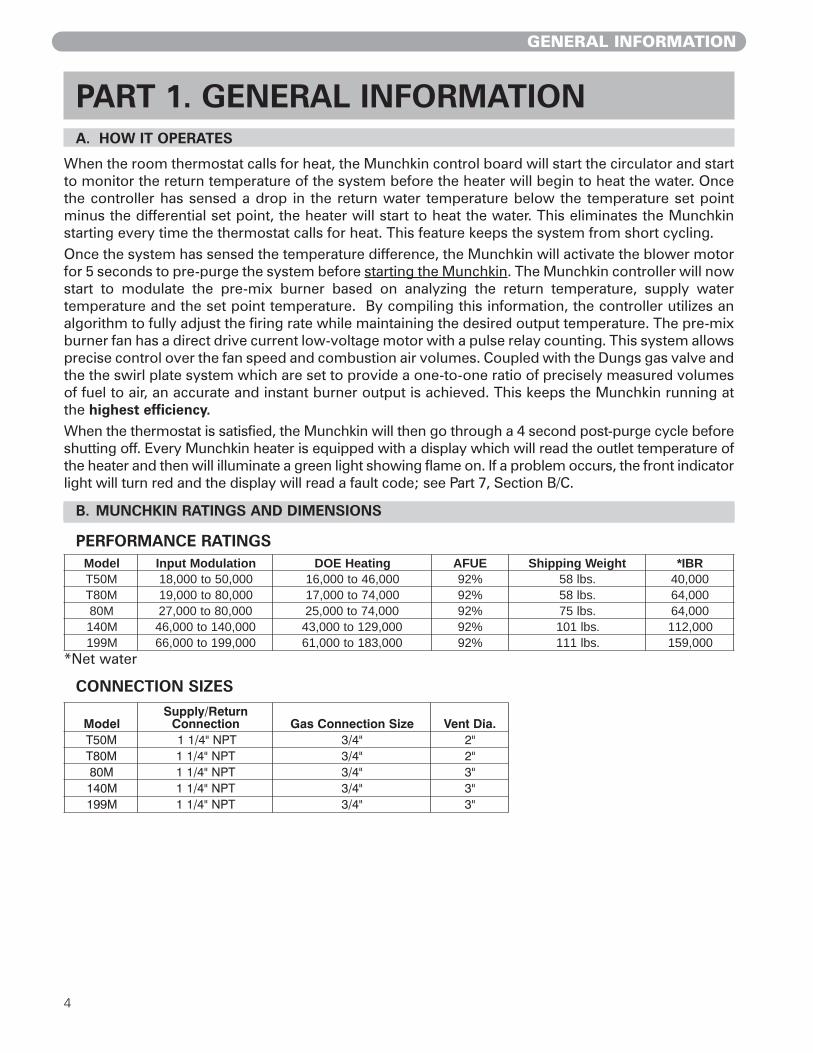
B. MUNCHKIN RATINGS AND DIMENSIONS
PERFORMANCE RATINGS
*Net water
CONNECTION SIZES
ledoM noitaludoMtupnI gnitaeHEOD EUFA thgieWgnippihS RBI*M05T 000,05ot000,81 000,64ot000,61 %29 .sbl85 000,04M08T 000,08ot000,91 000,47ot000,71 %29 .sbl85 000,46
M08 000,08ot000,72 000,47ot000,52 %29 .sbl57 000,46M041 000,041ot000,64 000,921ot000,34 %29 .sbl101 000,211M991 000,991ot000,66 000,381ot000,16 %29 .sbl111 000,951
PART 1. GENERAL INFORMATIONA. HOW IT OPERATES
When the room thermostat calls for heat, the Munchkin control board will start the circulator and startto monitor the return temperature of the system before the heater will begin to heat the water. Oncethe controller has sensed a drop in the return water temperature below the temperature set pointminus the differential set point, the heater will start to heat the water. This eliminates the Munchkinstarting every time the thermostat calls for heat. This feature keeps the system from short cycling.Once the system has sensed the temperature difference, the Munchkin will activate the blower motorfor 5 seconds to pre-purge the system before starting the Munchkin. The Munchkin controller will nowstart to modulate the pre-mix burner based on analyzing the return temperature, supply watertemperature and the set point temperature. By compiling this information, the controller utilizes analgorithm to fully adjust the firing rate while maintaining the desired output temperature. The pre-mixburner fan has a direct drive current low-voltage motor with a pulse relay counting. This system allowsprecise control over the fan speed and combustion air volumes. Coupled with the Dungs gas valve andthe the swirl plate system which are set to provide a one-to-one ratio of precisely measured volumesof fuel to air, an accurate and instant burner output is achieved. This keeps the Munchkin running atthe highest efficiency.When the thermostat is satisfied, the Munchkin will then go through a 4 second post-purge cycle beforeshutting off. Every Munchkin heater is equipped with a display which will read the outlet temperature ofthe heater and then will illuminate a green light showing flame on. If a problem occurs, the front indicatorlight will turn red and the display will read a fault code; see Part 7, Section B/C.
B. MUNCHKIN RATINGS AND DIMENSIONS
ledoMnruteR/ylppuS
noitcennoC eziSnoitcennoCsaG .aiDtneVM05T TPN"4/11 "4/3 "2M08T TPN"4/11 "4/3 "2M08 TPN"4/11 "4/3 "3M041 TPN"4/11 "4/3 "3M991 TPN"4/11 "4/3 "3

GENERAL INFORMATION
5
Figure 1-1
(NOTE: The Munchkin is rated atzero clearance to combustibles.)
80M/140M/199M
T50M/T80M
RECOMMENDED SERVICE CLEARANCES
Figure 1-2

GENERAL INFORMATION
6
Figure 1-3
T50M/T80MDIMENSIONS
GENERAL INFORMATION
7
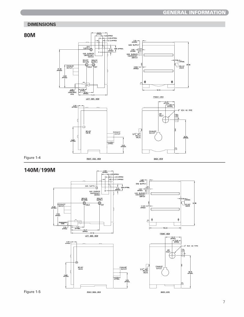
DIMENSIONS
80M
140M/199M
Figure 1-4
Figure 1-5

GENERAL INFORMATION
8
C. PRE-INSTALLATION REQUIREMENT
GENERAL
1. Munchkin Boilers are supplied complete-ly assembled as packaged boilers. Thepackage should be inspected for damageupon receipt and any damage to the unitshould be reported to the shipping com-pany and wholesaler. This boiler shouldbe stored in a clean, dry area.
2. Carefully read these instructions and besure to understand the function of allconnections prior to beginning installa-tion. Contact your Munchkin SalesRepresentative or the Heat TransferProducts, Inc. Customer ServiceDepartment for help in answering ques-tions.
3. This boiler must be installed by a quali-fied contractor. The boiler warranty maybe voided if the boiler is not installed cor-rectly.
4. This boiler needs to be installed on alevel floor. If the floor is not level, theboiler must be pitched back (1/4” pitchfor the 80M and 3/8” for the 140/199M.)This will assure proper flow to conden-sate drain in the bottom of the boiler.
CODES & REGULATIONS
Installation and repairs are to be performed instrict accordance with the requirements of stateand local regulating agencies and codes dealingwith boiler and gas appliance installation.
ACCESSIBILITY CLEARANCES
1. The Munchkin Boiler is certified for clos-et installations with zero clearance tocombustible construction. In addition, itis design certified for use on combustiblefloors.
2. Refer to Figure 1.1 and Figure 1.2 for therecommended clearance to allow for rea-sonable access to the boiler. Local codesor special conditions may require greaterclearances.
COMBUSTION AND VENTILATION AIR
1. The Munchkin Boiler is designed only foroperation with combustion air pipedfrom outside (sealed combustion). PVCpipe must be supplied between the airinlet connection at the rear of the boilerthrough an outside wall.
2. No additional combustion or ventilationair is required for this appliance.
3. Refer to Section 4 of this manual,Venting, for specific instructions for pip-ing combustion air.
PLANNING THE LAYOUT
1. Prepare sketches and notes showing thelayout of the boiler installation to mini-mize the possibility of interferences withnew or existing equipment, piping, vent-ing and wiring.
2. The following sections of this manualshould be reviewed for consideration oflimitations with respect to: a. Electrical Wiring: Part 2 b. Gas Connection: Part 3 c. Venting: Part 4 f. Piping: Part 5
Note: It is important to refer to thesite installation checklist in the backof this manual to assure proper andeffective installation.
WARNING Liquefied Petroleum (LP) Gas orPropane is heavier than air and, in theevent of a leak, may collect in lowareas such as basements or floordrains. The gas may then igniteresulting in a fire or explosion.
CAUTION Do not install this boiler on carpeting.

GENERAL INFORMATION / ELECTRICAL
9
Note: Service clearance of the Munchkin: See Section 1, Figures 1-1 and 1-2.If the Munchkin is set up for liquefied petroleum (LP) gas, some geographic areas follow the UniformMechanical Code, section 304.6, “Liquefied petroleum gas burning appliances shall not be installed ina pit, basement or similar location where heavier-than-air gas might collect. Appliances so fueled, shallnot be installed in a below grade under-floor space or basement unless such location is provided withan approved means for removal of unburned gas.”
PART 2. ELECTRICALA. ELECTRICAL CONNECTION
The electrical connection for the Munchkin is on the left hand side of the unit. There is a ½” knockoutlocation for an electrical connection for both the incoming power and the central heating circulatorconnection. All electrical wiring must be performed by a qualified licensed electrician in accordancewith National Electrical Code ANSI Z223.1//NFPA 54 to and/or the Canadian Electrical Code, Part 1 CSAC22.1, or to the applicable codes and standards. For your convenience, we have labeled all the wiresthat need to be connected to operate the Munchkin.
CAUTION The Munchkin is certified as an indoor appliance. Do not install the Munchkinoutdoors or locate where it will be exposed to freezing temperature. This includes allrelated piping and components. If the Munchkin is subjected to flood water orsubmersed in water, the Munchkin must be replaced.
CAUTION Condensation removal: This is a condensing high efficiency appliance, thereforecondensation removal must be addressed to avoid damage to surrounding area orappliance. See Part (4) Section E for Condensate Requirements.
WARNING
D. PRESSURE RELIEF VALVE
A pressure relief valve is installed into the front right side manifold. We recommend a WATTS ¾"M 335 MI valve or equivalent and meets the requirements of ANSI/ASME Heater and PressureVessel Code, Section IV or CSA B51; Heater, Pressure Vessel and Piping Code as applicable forheating heaters. A ¾" pipe must be directed to a floor drain or suitable location within 6" of a drainor floor. Protect from freezing, do not plug or cap pressure relief valve. Serious explosion causingproperty damage and or loss of life could result. Under no circumstances should the relief valvebe eliminated, capped or plugged.

10
ELECTRICAL
The electrical requirements are for standard 120 volts, 60 Hz 15 Amp service. This unit is wired with#18 awg and fused for no more than 15 Amps.
There are two ground points in the electrical compartment that must be connected to the buildingground system. Connect the building ground to the green ground screw and the green ground wireinside electrical box provided.
The Incoming Power Supply is connected to the Black (Hot) and the White (Neutral).The MunchkinControl board is polarity sensitive. If the polarity is reversed, the Munchkin control will not sense aflame and lock out the system. The Orange and Brown wire are provided to the supply of 120 volts tothe Central Heating Circulator. Connect the Orange (Hot) and the Brown (Neutral) directly to the CentralHeating Circulator.
Connect the gray wires to your heating thermostat (TT) connection. Your thermostat heat anticipatorsetting is .056 amp.
It is important that the electrical power is not turned on at this time. Double check all connections and thenturn the power on. The display that is provided with the Munchkin should now be reading the outlettemperature. Note: see Part 6/Startup Procedure section in the manual to change the temperature settingor run the heater.
CAUTION Electrical wiring on the Incoming Power and Central Heating Circulator shall beconnected directly to the intended connection source and not be connected togetherinside the electric box provided. An Electrical Short will result and the Control boardwill have to be replaced! If Electrical Requirements of the Central Heating Circulatorexceeds 4 amps (or 3 amps on HA models only) please follow the wiring diagrams onFigures 2-1, 2-2 and 2-3 (this section).
DANGER IT IS EXTREMELY IMPORTANT THAT THIS UNIT BE PROPERLY GROUNDED!
DANGER IT IS VERY IMPORTANT THAT THE BUILDING GROUND IS INSPECTED BY AQUALIFIED ELECTRICIAN PRIOR TO MAKING THIS CONNECTION!
DANGER The Orange wire for the Central Heating Circulator is Switched Hot and must have awire nut if not connected to the Central Heating Circulator. Failure to follow thisinstruction will result in a short, and the Control Board will have to be replaced.
CAUTION Do not power zone valves directly from the heater transformer. Doing so will greatlyreduce the life of the transformer. Use a separate transformer sized to handle the totalelectric load of all zone valves.

11
ELECTRICAL
NORMALLY OPEN
T
T
GROUNDBUS
SWITCH JUNCTION BOX120V 60 HZ
ELECTRICALSWITCH JUNCTION BOX
120V 60 HZ
ELECTRICAL
NORMALLY OPENTHERMOSTATCONNECTION
WIRING DIAGRAM WITHOUT CONNECTION TO CIRCULATOR
GREEN(GROUND)
GRAY
GRAY
CONNECTIONTHERMOSTAT
(NEUTRAL)WHITE
BLACK(HOT)
GRAY
T
TGRAY
WIRING DIAGRAM CONNECTING TO CIRCULATOR
BLACK
WHITE (NEUTRAL)
GREEN (GROUND)
DIAGRAM "A"
(HOT)BLACK
GREEN(GROUND)
(NEUTRAL)WHITE
DIAGRAM "B"
BRO
WN
(N
EU
TRAL)
ORAN
GE (
HO
T)
GREEN
(G
RO
UN
D)
ORAN
GE (
HO
T)
BRO
WN
(N
EU
TRAL)
GREEN
(G
RO
UN
D)
IMPORTANT NOTE:BE CERTAIN THAT THE ORANGEWIRE IS SECURELY CAPED.FAILURE TO DO SO COULD RESULT IN INJURY OR FIRE AND COULD DAMAGE THE CONTROL.
ORA
NGE
BROW
NGRE
EN
Figure 2-1: Connection Wiring Directly toCentral Heating Circulator
Figure 2-2: Connection Wiring without WiringCentral Heating Circulator
Note to Electrical Contractor: The orangewire is 120 Volt/4 Amp maximum for centralheating circulator only. Loads greater than 4amps or 3 amps for HA models only will blow thefuse on the board. The brown wire is the neu-tral wire for the central heating pump only.
Figure 2-3: For circulator amp loads greaterthan 4 amps (3 amps for “HA” models) use thewiring diagram shown above. The brown andorange wires on the Munchkin boiler will not beused in this application and should beterminated so they do not cause a short circuit.
5
T
1 2
3
6 4
T
1K1 1K2
BOILER "TT"
GRAY
ZONECIRCULATOR
120 VOLTL1 HOT (BLACK)
GRAY
BOILER "TT"
THERMOSTATZONE
R845ASWITCHINGRELAY ZONE
1K1
L2 NEUTRAL(WHITE)

12
GAS CONNECTION
PART 3. GAS CONNECTION
A. GAS CONNECTION
The gas supply shall have a maximum inlet pressure of lessthan 14" water column (350 mm), ½ pound pressure (3.5 kPa),and a minimum of 3.5" water column. The entire pipingsystem, gas meter and regulator must be sized properly toprevent pressure drop greater than 0.5" as stated in the NationalFuel Gas Code. This information is listed on the rating plate. It isvery important that you are connected to the type of gas as noted onthe rating plate. "LP" for liquefied petroleum, propane gas or, "Nat"natural or city gas. All gas connections must be approved by the local gas supplier, or utility in additionto the governing authority, prior to turning the gas supply on. The nipple provided is ½" and it ismandatory that a ¾" to ½" reducing coupling (provided) is used, threaded into the branch of a ¾" tee,and a drip leg fabricated, as per the National Fuel Gas code. You must ensure that the entire gas lineto the connection at the Munchkin is no smaller than ¾". Once all the inspections have beenperformed, the piping must be leak tested. If the leak test requirement is a higher test pressure thanthe maximum inlet pressure, you must isolate the Munchkin from the gas line. In order to do this, youmust shut the gas off using factory and field-installed gas cocks (following the lighting instructions inPart 6 Section B.) This will prevent high pressure. Failure to do so may damage the gas valve. In theevent the gas valve is exposed to a pressure greater than ½ PSI, 14" water column, the gas valve mustbe replaced. Never use an open flame (match, lighter, etc.) to check gas connections.
B. GAS PIPING
1. Run the gas supply line in accordance with all applicable codes.
2. Locate and install manual shutoff valves in accordance with state and local requirements.
C. GAS TABLE
Refer to Table (1) to size the supply piping to minimize pressure drop between meter or regulatorand unit.
Maximum Capacity of Pipe in Cubic Feet of Gas per Hour for Gas Pressures of 0.5 psi or Less and aPressure Drop of 0.3 Inch water Column
(TABLE 1) (Based on a 0.60 Specific Gravity Gas)
NominalIron Pipe Internal Length of Pipe (Feet)Size Diameter(inches) (inches) 10 20 30 40 50 60 70 80 90 100 125 150 175 200.3/4 .824 278 190 152 130 115 105 96 90 84 79 72 64 59 55} BTU'S1 1.049 520 350 285 245 215 195 180 170 160 150 130 120 110 100} PER1 1/4 1.380 1,050 730 590 500 440 400 370 350 320 305 275 250 225 210} HOUR1 1/2 1.610 1,600 1,100 890 760 670 610 560 530 490 460 410 380 350 320} X 1,000
WARNING Failure to follow all precautions could result in fire, explosion or death!

13
WARNING Failure to follow all precautions could result in fire, explosion or death!
GAS CONNECTION
It is recommended that a soapy solution be used to detect leaks. Bubbles will appear on the pipe toindicate a leak is present. The gas piping must be sized for the proper flow and length of pipe, to avoidpressure drop. Both the gas meter and the gas regulator must be properly sized for the total gas load.If you experience a pressure drop greater than 1" WC, the meter, regulator or gas line is undersized orin need of service. You can attach a manometer to the incoming gas drip leg, by removing the cap andinstalling the manometer. The gas pressure must remain between 3.5" and 14" during stand-by (static)mode and while in operating (dynamic) mode. If an in-line regulator is used, it must be a minimumof 10 feet from the Munchkin. It is very important that the gas line is properly purged by the gassupplier or utility. Failure to properly purge the lines or improper line sizing, will result in ignitionfailure. This problem is especially noticeable in NEW LP installations and also in empty tank situations.This can also occur when a utility company shuts off service to an area to provide maintenance to theirlines. This gas valve must not be replaced with a conventional gas valve under any circumstances. Asan additional safety feature, this gas valve has a flanged connection to the Venturi and blower.
DUNGS GAS VALVE
THROTTLE ADJUSTER(NOTE: IF FOR ANY REASON THE THROTTLE NEEDS TO BE ADJUSTED, IT IS VERY IMPORTANT THAT A "COMBUSTION ANAYLYZER" BE USED TO ENSURE SAFE AND PROPER OPERATION. TURN THE ADJUSTER TO THE (+) TO INCREASE GAS OR THE (-) TO DECREASE THE GAS SUPPLY. THIS ADJUSTMENT COULD AFFECT CO/CO% LEVELS. MAKE SURE THE LEVELS CORRESPOND TO THE CHART IN COMBUSTION SETTINGS.)
Fig. 3-1

14
VENTING
A. GENERAL
1. Install the boiler venting system in accor-dance with these instructions and with theNational Fuel Gas Code, ANSI Z223.1/NFPA54, CAN/CGA B149, and/or applicable provi-sions of local building codes.
2. This boiler is a direct vent appliance and islisted as a Category IV appliance withUnderwriters Laboratories, Inc. VENT ANDINTAKE AIR PIPE
B. APPROVED MATERIALS FOR EXHAUSTVENT AND INTAKE AIR PIPE
1. Use only Non Foam Core venting material.The following materials are approved for useas vent pipe for this boiler:a. Non Foam Core PVC (Polyvinyl Chloride)
Pipe conforming to ASTM D-1784 Class12454-B (formerly designated Type 1, Grade1).
b. Non Foam Core CPVC (Chlorinated PolyvinylChloride) Pipe conforming to ASTM D-1784Class 23447-B (formerly designated Type IV,Grade 1).
c. Non Foam Core ABS (Acrylonitrile-Butadiene- Styrene) Pipe conforming toASTM D3965 Class 3-2-2-2-2.
2. Cellular foam core piping may be used on airinlet piping only. Never use cellular foam corematerial for exhaust piping.
C. EXHAUST/VENT / AIR INTAKE PIPE LOCATION
1. Determine exhaust vent location:a. The vent piping for this boiler is approved for
zero clearance to combustible construction.b. See Figure 4.1 for an illustration of clear-
ances for location of exit terminals of direct-vent venting systems.
c. This boiler vent system shall terminate atleast 3 feet (0.9 m) above any forced airintake located within 10 ft (3 m). Note: thisdoes not apply to the combustion air intakeof a direct-vent appliance.
d. Provide a minimum of 1 foot distance fromany door, operable window, or gravity intakeinto any building.
e. Provide a minimum of 1 foot clearance fromthe bottom of the exit terminal above theexpected snow accumulation level. Snowremoval may be necessary to maintainclearance.
f. Provide 4 feet horizontal clearance fromelectrical meters, gas meters, gas regulators,and relief equipment. In no case shall theexit terminal be above or below the afore-mentioned equipment unless the 4 foot hor-izontal distance is maintained.
g. Do not locate the exit terminal over publicwalkways where condensate could dripand/or freeze and create a nuisance or haz-ard.
h. When adjacent to a public walkway, locateexit terminal at least 7 feet above grade.
i. Do not locate the exit termination directlyunder roof overhangs to prevent iciclesfrom forming.
j. Provide 3 feet clearance from the inside cor-ner of adjacent walls.
2. Determine air intake pipe location.a. Provide 1 foot clearance from the bottom of
the air inlet pipe and the level of maximumsnow accumulation. Snow removal may benecessary to maintain clearances.
b. Do not locate air intake pipe in a parking areawhere machinery may damage the pipe.
c. When venting with a two pipe system, max-imum distance between air intake andexhaust vent is 6 feet (1.8 m). Minimum dis-tance between exhaust vent and air intakeon single boiler is 8” (0.2 m) center-to-cen-ter. Minimum distance between vents andintakes on multiple boilers is 8” (0.2 m) cen-ter-to-center. See Figure 4.2.
WARNING This vent system will operate with a positivepressure in the pipe. Do not connect ventconnectors serving appliances vented by naturaldraft into any portion of mechanical draft systemsoperating under positive pressure.
WARNING Follow these venting instructions carefully. Failureto do so may result in severe personal injury, death,or substantial property damage.
WARNING Do not use Foam Core Pipe in any portion of theexhaust piping from this boiler. Use of Foam CorePipe may result in severe personal injury, death, orsubstantial property damage.
PART 4. VENTING

15
VENTING
Location of exit terminals of mechanical draft and direct-vent venting systems.(Reference: National Fuel Gas Code ANSI Z223.1/NFPA 54 2002).
Fig. 4.2 Multiple Vent Spacing**Note: Exhaust must extend out 1 foot
Figure 4.5: Multiple Boiler Installations
Fig. 4.3 Multiple Stainless Steel Vertical VentKit Installation – Front View
Fig. 4.4 Multiple Stainless Steel Horizontal Vent Kit Installation – Front View
Fig. 4.1

16
D. EXHAUST VENT AND INTAKE AIR PIPE SIZING
1. For the T50 and T80 Boilers the exhaust ventand air intake pipes should be 2" Schedule 40or 80.
2. For the 80M, 140M, 199M the exhaust ventand air intake pipes should be 3" Schedule 40or 80.
3. The total combined equivalent length ofexhaust vent and intake air pipe should notexceed 85 feet.a. The equivalent length of elbows, tees, and
other fittings are listed in the Friction LossTable 4.1.
*Friction loss for long radius elbow is 1 foot less.b. For example: If the exhaust vent has two 90°
elbows and 10 feet of PVC pipe we will cal-culate:
Exhaust Vent Pipe Equivalent Length = (2x5)+10=20 feetFurther, if the intake air pipe has two 90°elbows, one 45° elbow and 10 feet of PVCpipe, the following calculation applies:
Air Intake Pipe Equivalent Length = (2x5)+3+10=23 feetFinally, if a concentric vent kit is used wefind:
Total Combined Equivalent Length = 20+23+3=46 feetTherefore, the total combined equivalentlength is 46 feet which is well below themaximum of 85 feet.
c. The intake air pipe and the exhaust vent areintended to penetrate the same wall or roofof the building.
d. Effort should be made to keep a minimumdifference in equivalent length between theair intake pipe and the exhaust vent.
4. The minimum combined equivalent length is16 equivalent feet.
5. The maximum combined equivalent lengthcan be extended by increasing the diameterof the vent pipe. However, the transitionsshould begin a minimum of 15 equivalent feetfrom the boiler.a. Transitions should always be made in verti-
cal sections of pipe to prevent the conden-sate from pooling in the vent pipe.
b. Use a 3” x 2” reducing coupling to transitionfrom the T50 and T80 boiler connections toa 3” vent.
c. Use a 4” x 3” reducing coupling to transitionfrom the 80M, 140M, and 199M boiler con-nections to 4” vent.
d. The maximum equivalent length for theincreased diameter vent pipes is 125 feet.
e. If the transition occurs at a distance greaterthan 15 equivalent feet from the boiler, themaximum equivalent length will be reduced.See Table 4.2. Standard Vent Pipe is 2" andOversized Vent Pipe is 3" for T50 and T80.Standard Vent Pipe is 3" and Oversized VentPipe is 4" for 80M through 199M.
E. EXHAUST VENT AND AIR INTAKE PIPEINSTALLATION
1. On the T50 and T80 the 2" exhaust vent con-nection is located on the top, right side of theboiler and the air intake is on the top, left side.See Figure 10.1. The air intake connection isintended for a slip fit. No sealant or adhesiveis required.
2. On the 80M, 140M, and 199M Boilers the 3"exhaust vent connection is located on the rearof the boiler and the air intake is higher andtoward the left side when the boiler is viewedfrom the front. The air intake connection isintended for a slip fit. No sealant or adhesiveis required.
VENTING
TransitionPoint
(ft fromboiler
TEL ofStandard 2"or 3" VentPipe (ft)
TEL ofOversized 3"
or 4" VentPipe (ft)
MaximumTEL of all
Vent Pipe (ft)
15 30 95 125
20 40 77-1/2 117-1/2
25 50 60-1/2 110-1/2
30 60 43 103
35 70 26 96
40 80 8-1/2 88-1/2
None 85 0 85TEL = Total Equivalent Length
FRICTION LOSS EQUIVALENT IN PIPING AND FITTINGS
FITTINGS OR PIPING EQUIVALENT FEET
2" 3" 4" 6"
90 DEGREE ELBOW* 5' 5' 3' 1'
45 DEGREE ELBOW 3' 3' 1' 1'
COUPLING 0' 0' 0' 0'
AIR INLET TEE 0' 0' 0' 0'
STRAIGHT PIPE 1' 1' 1' 0.5
CONCENTRIC VENT KIT 3' 3' N/A N/A
V500 2" VENT KIT 1' N/A N/A N/A
V1000 3" VENT KIT N/A 1' N/A N/A
V2000 4" VENT KIT N/A N/A 1' N/A
Table 4.2: Vent Termination Kits
Table 4.1

17
VENTING
3. Use only solid PVC, CPVC, or ABS schedule40 or 80 pipe. FOAM CORE PIPING IS NOTAPPROVED.
4. Remove all burrs and debris from joints andfittings.
5. All joints must be properly cleaned, primed,and cemented. Use only cement and primerapproved for use with the pipe material.Cement must conform to ASTM D2564 forPVC or CPVC pipe and ASTM D2235 for ABSpipe.
6. Horizontal lengths of exhaust vent must slopeback towards the boiler not less than ¼" per
foot to allow condensate to drain from thevent pipe. If the vent pipe must be pipedaround an obstacle that causes a low point inthe pipe, a drain pipe must be connected toallow condensate to drain.
7. All piping must be fully supported. Use pipehangers at a minimum of 4 foot intervals toprevent sagging of the pipe where conden-sate may form.
8. Do not use the boiler to support any piping.
9. A screened straight coupling is provided withthe boiler for use as an outside exhaust termi-nation.
10. A screened inlet air tee is provided with theboiler to be used as an outside intake termi-nation.
11. The following information on Table 4.3 areoptional intake air/exhaust vent terminationsavailable from Heat Transfer Products, Inc.
WARNING All joints of positive pressure vent systems must besealed completely to prevent leakage of flueproducts into the living space.
Description StockCode
2" PVC Concentric Vent Termination Kit KGAVT0601CVT
3" PVC Concentric Vent Termination Kit KGAVT0501CVT
2" Stainless Steel Vent Termination Kit V500
3" Stainless Steel Vent Termination Kit V1000
4" Stainless Steel Vent Termination Kit V2000
Table 4.3: Vent Termination Kits

VENTING
18
F. HEATER REMOVAL FROM A COMMON VENT SYSTEM
At the time of removal of an existing heater, the following steps shall be followed with each appli-ance remaining connected to the common venting system placed in operation, while the other appli-ances remaining connected to common venting system are not operating.
1. Seal any unused openings in the common venting system. 2. Visually inspect the venting system for proper size and horizontal pitch to determine if there
is blockage, leakage, corrosion or other deficiencies that could cause an unsafe condition.3. If practical, close all building doors, windows and all doors between the space in which the
appliance remains connected to the common venting system located and other spaces in thebuilding. Turn on clothes dryers and any appliances not connected to the common ventingsystem. Turn on any exhaust fans, such as range hoods and bathroom exhausts, at maximumspeed. Do not operate a summer exhaust fan. Close all fireplace dampers.
4. Place in operation the appliance being inspected. Follow the lighting instructions. Adjust thethermostat so the appliance will operate continuously.
5. Test for spillage at the draft hood relief opening after 5 minutes of main burner operation. Usethe flame of a match or candle or smoke from a cigarette.
6. After it has been determined that each appliance remaining connected to common ventingsystem properly vents when tested as outlined, return doors, windows, exhaust fans, fire-place dampers and any other gas burning appliance to their previous condition of use.
7. Any improper operation of the common venting system should be corrected so the installa-tion conforms with the National Fuel Gas Code, ANSI Z223.1. When resizing any portion ofthe common venting system, the common venting system should be resized to approach theminimum size as determined using the appropriate tables in Appendix G in the National FuelGas Code , ANSI Z 223.1
G. CONDENSATE REMOVAL
This is a condensing high efficiency appliance, therefore this unit has a condensate removal system.Condensate is nothing more than water vapor, derived from the combustion products, similar to anautomobile when it is initially started. It is very important that the condensate line is sloped awayfrom and down to a suitable inside drain, if the condensate outlet on the Munchkin is lower than thedrain, you must use a condensate removal pump (kit available from Heat Transfer Products, Inc.) Acondensate filter, if required by local authorities can be made up of lime crystals, marble orphosphate chips will neutralize the condensate. This can be done in the field by the installer or youmay purchase one from Heat Transfer Products, Inc. It is also very important that the condensate lineis not exposed to freezing temperatures, or any other type of blockage. Plastic tubing should be theonly material used for the condensate line. Steel, brass, copper or others will be subject to corrosionor deterioration. A second vent may be necessary to prevent condensate line vacuum lock if a longhorizontal run is used. Also, an increase in pipe size may be necessary to drain properly. Support ofthe condensation line may be necessary to avoid blockage of the condensate flow.
DANGER The Munchkin is not intended to be common vented with any other
existing appliance!

19
VENTING
GENERAL NOTE: All vent pipes must be glued, properly supported and the exhaust must be pitched aminimum of a ¼" per foot back to the heater (to allow drainage of condensate).
DIAGRAMS FOR SIDEWALL VENTING
Figure 4-1a Figure 4-2a

VENTING
20
Figure 4-3a
Figure 4-4a
GENERAL NOTE: All vent pipes must be glued, properly supported and the exhaust must be pitched aminimum of a ¼" per foot back to the heater (to allow drainage of condensate).

VENTING
21
Figure 4-5a
Figure 4-6a
DIAGRAMS FOR VERTICAL VENTING
GENERAL NOTE: All vent pipes must be glued, properly supported and the exhaust must be pitched aminimum of a ¼" per foot back to the heater (to allow drainage of condensate).
22
PIPING
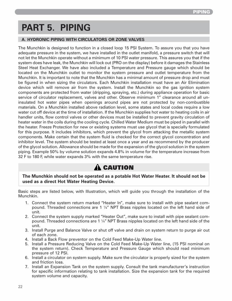
PART 5. PIPING A. HYDRONIC PIPING WITH CIRCULATORS OR ZONE VALVES
The Munchkin is designed to function in a closed loop 15 PSI System. To assure you that you haveadequate pressure in the system, we have installed in the outlet manifold, a pressure switch that willnot let the Munchkin operate without a minimum of 10 PSI water pressure. This assures you that if thesystem does have leak, the Munchkin will lock out (PRO on the display) before it damages the StainlessSteel Heat Exchanger. We have also included a Temperature and Pressure gauge which should belocated on the Munchkin outlet to monitor the system pressure and outlet temperature from theMunchkin. It is important to note that the Munchkin has a minimal amount of pressure drop and mustbe figured in when sizing the circulators. Each Munchkin installation must have an Air Eliminationdevice which will remove air from the system. Install the Munchkin so the gas ignition systemcomponents are protected from water (dripping, spraying, etc.) during appliance operation for basicservice of circulator replacement, valves and other. Observe minimum 1” clearance around all un-insulated hot water pipes when openings around pipes are not protected by non-combustiblematerials. On a Munchkin installed above radiation level, some states and local codes require a lowwater cut off device at the time of installation. If the Munchkin supplies hot water to heating coils in airhandler units, flow control valves or other devices must be installed to prevent gravity circulation ofheater water in the coils during the cooling cycle. Chilled Water Medium must be piped in parallel withthe heater. Freeze Protection for new or existing systems must use glycol that is specially formulatedfor this purpose. It includes inhibitors, which prevent the glycol from attacking the metallic systemcomponents. Make certain that the system fluid is checked for the correct glycol concentration andinhibitor level. The system should be tested at least once a year and as recommend by the producerof the glycol solution. Allowance should be made for the expansion of the glycol solution in the systempiping. Example 50% by volume solution expands 4.8% in volume for the temperature increase from32 F to 180 F, while water expands 3% with the same temperature rise.
Basic steps are listed below, with Illustration, which will guide you through the installation of theMunchkin.
1. Connect the system return marked “Heater In”, make sure to install with pipe sealant com-pound. Threaded connections are 1 ¼” NPT Brass nipples located on the left hand side ofunit.
2. Connect the system supply marked “Heater Out”, make sure to install with pipe sealant com-pound. Threaded connections are 1 ¼” NPT Brass nipples located on the left hand side of theunit.
3. Install Purge and Balance Valve or shut off valve and drain on system return to purge air outof each zone.
4. Install a Back Flow preventor on the Cold Feed Make-Up Water line.5. Install a Pressure Reducing Valve on the Cold Feed Make-Up Water line, (15 PSI nominal on
the system return). Check Temperature and Pressure Gauge which should read minimumpressure of 12 PSI.
6. Install a circulator on system supply. Make sure the circulator is properly sized for the systemand friction loss.
7. Install an Expansion Tank on the system supply. Consult the tank manufacturer’s instructionfor specific information relating to tank installation. Size the expansion tank for the requiredsystem volume and capacity.
CAUTION The Munchkin should not be operated as a potable Hot Water Heater. It should not beused as a direct Hot Water Heating Device.

23
PIPING
8. Install an Air Elimination Device on the system supply.9. Install a drain valve at the lowest point of the system. Note: The Munchkin can not be drained
completely of water without purging the unit with an air pressure 15 PSI. 10. The Safety Relief Valve is installed at the factory located on the right hand side of Munchkin.
Pipe the discharge of safety relief valve to prevent injury in the event of pressure relief. Pipethe discharge to a drain. Provide piping that is the same size as the safety relief valve outlet.Never block the outlet of safety relief valve.
11. In compliance with ASME CSD-1, a low water cut-off device should be properly connected inthe field, both electrically and mechanically.
See the piping illustrations included in this section, Figs. 5-3 to 5-11 for suggested guidelines inpiping the Munchkin heater with either zone valves or circulator pumps.*Please note that these illustrations are meant to show system piping concept only, the installeris responsible for all equipment and detailing required by local codes.
B. CIRCULATOR SIZING
The Munchkin Heat Exchanger does have pressure drop which must be considered in your systemdesign. Refer to the graph below for pressure drop through the Munchkin Heat Exchanger.
BOILER TACO P/N GRUNDFOS P/NT50M/T80M/80M 007 * UPS15-58 FC SPD 2
140M 0010 * 26-64 F199M 0011 * 26-96 F
* THE RECOMMENDED CIRCULATORS ARE BASED ON 1 GPM PER 10,000 BTU/HR W/20
0123456789
1011121314151617181920
1 2 3 4 5 6 7 8 9 10 11 12 13 14 15 16 17 18 19 20 21Flow in Gallons per Minute
Fric
tion in
Feet
of
Head
MUNCHKIN T50M MUNCHKIN T80M/80MMUNCHKIN 140M MUNCHKIN 199M
Figure 5-1
24
PIPING
C. FILL AND PURGE HEATING SYSTEM
• Attach the hose to balance and purge hose connector or drain valve and run hose to near-est drain
• Close the other side of the balance and purge valve or the shut off valve after the drain. • Open first zone balance and purge or drain valve to let water flow out the hose. If zone
valves are used, open the valves one at a time manually. (Note: please check valve manu-facturer’s instruction prior to opening valves manually, so as not to damage the valve.)
• Manually operate fill valve regulator. When water runs out of the hose, while it’s connect-ed to the balance and purge valve or drain you will see a steady stream or water (with nobubbles). Close balance and purge valve or drain to stop the water from flowing.Disconnect the hose and connect it to next zone to be purged.
• Repeat this procedure for additional zones (one at time).
Upon completion, make sure that the fill valve is in automatic position and each zone balance andpurge or shut off is in an open position and zone valves are positioned for automatic operation.
1. Glycol in hydronic applications which is specially formulated for this purpose includesinhibitors which prevent the glycol from attacking metallic system components. Make certainthat the system fluid is checked for the correct glycol concentration and inhibitor level.
2. The glycol solution should be tested at least once a year and as recommended by the glycolmanufacturer.
3. Anti-freeze solutions expand more than water. For example a 50% by volume solutionexpands 4.8% in volume for a temperature increase from 32° F to 180° F, while water expands3% with the same temperature rise. Allowances must be made for this expansion in the sys-tem design.
4. A 30% mixture of glycol will result in a BTU output loss of 15% with a 5% increase in headagainst system circulator.
5. A 50% mixture of glycol will result in a BTU output loss of 30% with a 50% increase in headagainst system circulator.
CAUTION For installation that incorporates standing Iron Radiation and systems with manualvents at the high points. Follow above section and starting with the nearest manualair vent, open vent until water flows out, then close vent. Repeat procedure, workingyour way toward furthest air vent. It may be necessary to install a basket strainer inan older system where larger amounts of sediment may be present. Annual cleaningof the strainer may be necessary.
WARNING Use only inhibited propylene glycol solutions which are specially formulated forhydronic systems. Ethylene glycol is toxic and can attack gaskets and seals used inhydronic systems.
CAUTION It is highly recommended that you carefully follow the glycol manufacturer’srecommended concentrations, expansion requirements and maintenancerecommendations (pH additive breakdown, inhibitor reduction, etc.). You mustcarefully figure the additional friction loss in the system as well as the reduction inheat transfer co-efficients.

25
PIPING
Piping Symbol Legend
circulator (w/ isolation flanges)
gate valve
globe valve
ball valve
swing-check valve
flow-check valve
spring-loaded check valve
hose bib / boiler drain
thermostatic radiator valveTRV (straight)
circuit setter
manual 3-way valve
zone valve
air separator
backflow preventer
diaphragm-type expansion tank
pressure reducing valve
diff. pressure bypass
anti-scald ratedmixing valve
pressure gauge
4-way motorized mixing valve
3-way motorized mixing valve
pressure relief valve
float -typeair vent
heat exchanger
union
Munchkin heater
radiant manifold
Super Storindirect DHW tank
vacuum breaker
thermostatic radiator valveTRV (angle)
circulator w/ integral flow check)
D. PIPING ILLUSTRATIONS
Fig. 5-2

26
PIPING
Standard Munchkin boilerRetrofit piping (zoning with valves)Space heating mode
Munchkin boiler
P1
Super Storindirect DHW tank
T/P
Drawing 1A
make-up water
zone valves
purgingvalves
NOTES:1. This drawing is meant to show system piping concept only.
Installer is responsible for all equipment & detailing required by local codes.2. Adjust flow bypass valve for the following minimum boiler flow rates in any operating mode:
Munchkin model T50M: 3 gpmMunchkin model T80M: 3 gpmMunchkin model 80M: 3 gpm Munchkin model 140M: 5 gpmMunchkin model 199M: 7 gpm
3. The minimum pipe size for connecting a Super Stor water heater is 1 inch.4. The minimum pipe size for connecting a Munchkin boiler is 1.25 inches.5. All pumps are shown with isolation flanges. The alternative is standard flanges with full port ball valves. 6. The anti-scald mixing valve is recommended if the DHW temperature is set above the factory setting of 119˚F.7. Install a minimum of 12 diameters of straight pipe upstream of all circulators.8. A purging valve may be used in lieu of the ball valve / hose bib combination shown.
V1
flowbypassvalve
anti-scaldmixing valve
coldwater
OFF
Fig. 5-3NOTE: FOR VISION PIPING APPLICATIONS, REFER TO THE VISION INSTALLATION PIPING DIAGRAMS.

27
PIPING
Standard Munchkin boilerRetrofit piping (zoning with valves)Domestic water heating mode
Munchkin boiler
P1
Super Storindirect DHW tank
T/P
Drawing 1B
make-up water
purgingvalves
V1
zone valves
flowbypassvalve
anti-scaldmixing valve
NOTES:1. This drawing is meant to show system piping concept only.
Installer is responsible for all equipment & detailing required by local codes.2. Adjust flow bypass valve for the following minimum boiler flow rates in any operating mode:
Munchkin model T50M: 3 gpmMunchkin model T80M: 3 gpmMunchkin model 80M: 3 gpm Munchkin model 140M: 5 gpmMunchkin model 199M: 7 gpm
3. The minimum pipe size for connecting a Super Stor water heater is 1 inch.4. The minimum pipe size for connecting a Munchkin boiler is 1.25 inches.5. All pumps are shown with isolation flanges. The alternative is standard flanges with full port ball valves. 6. The anti-scald mixing valve is recommended if the DHW temperature is set above the factory setting of 119˚F.7. Install a minimum of 12 diameters of straight pipe upstream of all circulators.8. A purging valve may be used in lieu of the ball valve / hose bib combination shown.
coldwater
OFF
OFF
OFF
OFF
Fig. 5-4NOTE: FOR VISION PIPING APPLICATIONS, REFER TO THE VISION INSTALLATION PIPING DIAGRAMS.

28
PIPING
Standard Munchkin boilerPreferred piping (zoning with valves)Space heating mode
Munchkin boiler
P1
Super Storindirect DHW tank
T/P
Drawing 2A
make-up water
zone valves
NOTES:1. This drawing is meant to show system piping concept only.
Installer is responsible for all equipment & detailing required by local codes.2. Adjust differential pressure bypass valve to eliminate any flow velocity noise when zone with highest pressure
drop operates by itself.3. The minimum pipe size for connecting a Super Stor water heater is 1 inch.4. The minimum pipe size for connecting a Munchkin boiler is 1.25 inches.5. All pumps are shown with isolation flanges. The alternative is standard flanges with full port ball valves. 6. The anti-scald mixing valve is recommended if the DHW temperature is set above the factory setting of 119˚F.7. Install a minimum of 12 diameters of straight pipe upstream of all circulators.8. A purging valve may be used in lieu of the ball valve / hose bib combination shown.9. A minimum of 6 pipe diameters of straight pipe shall be installed upstream and downstream
of all closely spaced tees.
V1
differentialpressurebypassvalve
anti-scaldmixing valve
purgingvalves
closelyspaced
tees
P2
coldwater
OFF
Fig. 5-5NOTE: FOR VISION PIPING APPLICATIONS, REFER TO THE VISION INSTALLATION PIPING DIAGRAMS.

29
PIPING
Standard Munchkin boilerPreferred piping (zoning with valves)Domestic water heating mode
Munchkin boiler
P1
Super Storindirect DHW tank
T/P
Drawing 2B
make-up water
V1
zone valves
anti-scaldmixing valve
purgingvalves
closelyspaced
tees
differentialpressurebypassvalve
P2
NOTES:1. This drawing is meant to show system piping concept only.
Installer is responsible for all equipment & detailing required by local codes.2. Adjust differential pressure bypass valve to eliminate any flow velocity noise when zone with highest pressure
drop operates by itself.3. The minimum pipe size for connecting a Super Stor water heater is 1 inch.4. The minimum pipe size for connecting a Munchkin boiler is 1.25 inches.5. All pumps are shown with isolation flanges. The alternative is standard flanges with full port ball valves. 6. The anti-scald mixing valve is recommended if the DHW temperature is set above the factory setting of 119˚F.7. Install a minimum of 12 diameters of straight pipe upstream of all circulators.8. A purging valve may be used in lieu of the ball valve / hose bib combination shown.9. A minimum of 6 pipe diameters of straight pipe shall be installed upstream and downstream
of all closely spaced tees.
coldwater
OFF
OFF
OFF
OFF
Fig. 5-6NOTE: FOR VISION PIPING APPLICATIONS, REFER TO THE VISION INSTALLATION PIPING DIAGRAMS.

30
PIPING
Standard Munchkin boilerPreferred piping (zoning with circulators)Space heating mode
NOTES:1. This drawing is meant to show system piping concept only.
Installer is responsible for all equipment & detailing required by local codes.2. All closely spaced tees shall be within 4 pipe diameter center to center spacing.3. A minimum of 6 pipe diameters of straight pipe shall be installed upstream and downstream
of all closely spaced tees.4. The minimum pipe size for connecting a Super Stor water heater is 1 inch.5. The minimum pipe size for connecting a Munchkin boiler shall be 1.25 inches.6. All pumps are shown with isolation flanges. The alternative is standard flanges with full port ball valves. 7. The anti-scald mixing valve is recommended if the DHW temperature is set above the factory setting of 119˚F.8. Install a minimum of 12 diameters of straight pipe upstream of all circulators.9. A purging valve may be used in lieu of the ball valve / hose bib combination shown.
Munchkin boiler
make-up water
Super Storindirect DHW tank
closelyspaced
tees
P1
P2
zonecirculators
T/P
space heating zone circuit
Drawing 2C
purgingvalves
anti-scaldmixing valve
coldwater
Fig. 5-7NOTE: FOR VISION PIPING APPLICATIONS, REFER TO THE VISION INSTALLATION PIPING DIAGRAMS.

31
PIPING
Standard Munchkin boilerPreferred piping (zoning with circulators)Domestic water heating mode
Munchkin boiler
make-up water
Super Storindirect DHW tank
closelyspaced
tees
P2
zonecirculators
T/P
space heating zone circuit
Drawing 2D
purgingvalves
NOTES:1. This drawing is meant to show system piping concept only.
Installer is responsible for all equipment & detailing required by local codes.2. All closely spaced tees shall be within 4 pipe diameter center to center spacing.3. A minimum of 6 pipe diameters of straight pipe shall be installed upstream and downstream
of all closely spaced tees.4. The minimum pipe size for connecting a Super Stor water heater is 1 inch.5. The minimum pipe size for connecting a Munchkin boiler shall be 1.25 inches.6. All pumps are shown with isolation flanges. The alternative is standard flanges with full port ball valves. 7. The anti-scald mixing valve is recommended if the DHW temperature is set above the factory setting of 119˚F.8. Install a minimum of 12 diameters of straight pipe upstream of all circulators.9. A purging valve may be used in lieu of the ball valve / hose bib combination shown.
anti-scaldmixing valve
closelyspaced
tees
P1
coldwater
Fig. 5-8NOTE: FOR VISION PIPING APPLICATIONS, REFER TO THE VISION INSTALLATION PIPING DIAGRAMS.
32
PIPING
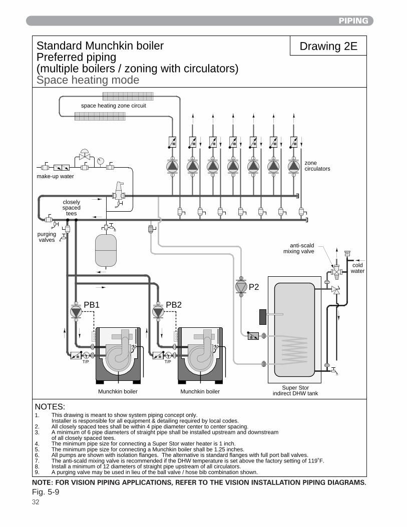
Standard Munchkin boilerPreferred piping (multiple boilers / zoning with circulators)Space heating mode
NOTES:1. This drawing is meant to show system piping concept only.
Installer is responsible for all equipment & detailing required by local codes.2. All closely spaced tees shall be within 4 pipe diameter center to center spacing.3. A minimum of 6 pipe diameters of straight pipe shall be installed upstream and downstream
of all closely spaced tees.4. The minimum pipe size for connecting a Super Stor water heater is 1 inch.5. The minimum pipe size for connecting a Munchkin boiler shall be 1.25 inches.6. All pumps are shown with isolation flanges. The alternative is standard flanges with full port ball valves. 7. The anti-scald mixing valve is recommended if the DHW temperature is set above the factory setting of 119˚F.8. Install a minimum of 12 diameters of straight pipe upstream of all circulators.9. A purging valve may be used in lieu of the ball valve / hose bib combination shown.
Drawing 2E
make-up water
closelyspaced
tees
space heating zone circuit
purgingvalves
Munchkin boiler
T/P
PB1
P2
Super Storindirect DHW tank
anti-scaldmixing valve
Munchkin boiler
T/P
PB2
zonecirculators
coldwater
Fig. 5-9NOTE: FOR VISION PIPING APPLICATIONS, REFER TO THE VISION INSTALLATION PIPING DIAGRAMS.

PIPING
33
Standard Munchkin boilerPreferred piping (multiple boilers / zoning with circulators)Domestic water heating mode
NOTES:1. This drawing is meant to show system piping concept only.
Installer is responsible for all equipment & detailing required by local codes.2. All closely spaced tees shall be within 4 pipe diameter center to center spacing.3. A minimum of 6 pipe diameters of straight pipe shall be installed upstream and downstream
of all closely spaced tees.4. The minimum pipe size for connecting a Super Stor water heater is 1 inch.5. The minimum pipe size for connecting a Munchkin boiler shall be 1.25 inches.6. All pumps are shown with isolation flanges. The alternative is standard flanges with full port ball valves. 7. The anti-scald mixing valve is recommended if the DHW temperature is set above the factory setting of 119˚F.8. Install a minimum of 12 diameters of straight pipe upstream of all circulators.9. A purging valve may be used in lieu of the ball valve / hose bib combination shown.
Drawing 2F
make-up water
closelyspaced
tees
space heating zone circuit
purgingvalves
Munchkin boiler
T/P
PB1
P2
Super Storindirect DHW tank
anti-scaldmixing valve
Munchkin boiler
T/P
PB2
zonecirculators
coldwater
Fig. 5-10NOTE: FOR VISION PIPING APPLICATIONS, REFER TO THE VISION INSTALLATION PIPING DIAGRAMS.

34
START-UP PROCEDURES
PART 6. START-UP PROCEDURES A. SEQUENCE OF OPERATION
1. When power is first applied to the control, the control display will read the outlet tempera-ture. The control will initially run through a self-diagnostic routine and then go into its oper-ating mode. If there is no call for heat, the System will go into an idle state.
2. If the thermostat is calling for heat, the control will apply power to the circulator pump. If thecontrol determines the water temperature is below the programmed set point value minusthe switching differential, the control will initiate a heating cycle.
3. The control then performs selected system diagnostic checks. If all checks are successfullypassed, a pre-purge cycle is initiated (the blower will be on maximum speed).
4. When the pre-purge period is complete, power is applied to the spark ignitor for approxi-mately 6 seconds. Approximately 2 seconds later, we verify flame. If a flame is not verifiedduring the trial-for-ignition, the gas valve is immediately closed and the control will return tostep. After three trials, if a flame is not verified, the control will go into a lockout mode. If aflame is confirmed, the control enters the heating mode. The fire rate will be based on theproprietary algorithm.
5. When water temperature reaches the temperature set point value plus 10 degrees F (or if thethermostat call-for-heat is satisfied), the gas valve is closed and the control enters a post-purge state (the blower will be on maximum speed). NOTE: If the thermostat is still callingfor heat, the circulator pump will continue to run until the thermostat call for heat is satis-fied.
6. When the post-purge is complete, the control enters an idle state while continuing to moni-tor temperature and the state of other system devices. If a call-for-heat is received, the con-trol will automatically return to step 2 in sequence and repeat the entire operating cycle.
During the idle state and heat state, if the control detects an improper operating state from externaldevices, such as the high-limit switch, the red light on the control will illuminate an error code willappear in the display.
B. ITEMS TO BE CHECKED BEFORE LIGHTING THE MUNCHKIN
It is recommended that you read the General Information Section (Part 1) to get a better under-standing how the Munchkin operates before you start the unit.
1. Make sure that you follow the Lighting instruction before running the Munchkin.
2. Make sure the unit has a minimum water supply pressure of 10 PSI or a fault code of PrO willappear in the display. While this Fault code is on the display the unit will not operate unit untilthe water pressure is brought above 10 PSI. This Fault code is caused by the Water pressureswitch being open for more than 5 seconds which is an indication your system pressure isbelow 10 PSI. Increase the water pressure in the system until the pressure gauge reads 10psi.This code will disappear once the Water Pressure switch is closed, which will allow you tostart the Munchkin.
3. Check to see if all the electrical connections are on securely.
4. Make sure that the Gas is turned on inside the cabinet and outside of the Munchkin.
5. Double check the temperature setting (Note: The Munchkin is factory set at 180 degrees)
6. Make sure the unit is properly grounded and the electrical wiring meets the requirements ofthe electrical section (Part 2).
7. Turn on the power to the Munchkin. The Temperature of the Munchkin Outlet will appear inthe display provided. If a fault code appears, correct the fault before operating. Make sure that

35
START-UP PROCEDURES
the room thermostat is connected and turn the room thermostat up above room temperatureto start the combustion blower fan to run the Munchkin. The Munchkin will now run its pre-purge cycle, then begin running, which will be indicated by the Green light illuminating under“Flame On” in your display.
C. LIGHTING INSTRUCTIONS
FOR YOUR OWN SAFETY READ BEFORE OPERATING1. This appliance does not have pilot. It is equipped with an ignition device which automatical-
ly lights the burner. Do not try to light the burner by hand.
2. BEFORE OPERATING smell all around the appliance area for gas. Be sure to smell next to thefloor because some gas is heavier than air and will settle on the floor.
WHAT TO DO IF YOU SMELL GAS• Do not try to light any appliance.• Do not touch any electric switch; do not use any phone in your building.• Immediately call your gas supplier from a neighbor's phone. Follow the gas suppliers'
instructions.• If you cannot reach your gas supplier, call the fire department.
3. Turn on gas shutoff valve (located inside of the Heater) so that the handle is aligned with thegas pipe. If the handle will not turn by hand, don't try to repair it, call a qualified service tech-nician. Force or attempted repair may result in a fire or explosion.
4. Do not use this appliance if any part has been under water. Immediately call a qualified serv-ice technician to inspect the appliance and to replace any part of the control system and anygas control which has been under water.
5. The Munchkin Boiler shall be installed so the gas ignition system components are protectedfrom water (dripping, spraying, rain, etc.) during appliance operation and service (circulatorreplacement, condensate trap, control replacement, etc.)
D. OPERATING INSTRUCTIONS
1. STOP! Read the safety information in Part 6.
2. Set the thermostat to the lowest setting.
3. Turn off all electric power to the appliance.
4. This appliance is equipped with an ignition device which automatically lights the burner. Donot try to light the burner by hand.
5. Remove front cover.
6. Turn gas shutoff valve to “off”.
7. Wait five (5) minutes to clear out any gas. If you then smell gas, STOP! Follow Part 6, SectionB/Lighting Instructions in the safety information. If you don't smell gas, go to the next step.
8. Turn the gas shutoff valve counter clockwise to “on”. The handle will be horizontal.
9. Replace the Front Cover.
10. Turn on all electric power to appliance.
11. Set the thermostat to the desired setting.
DANGER If you do not follow these instructions exactly, a fire or explosion may
result, causing property damage, personal injury or loss of life.

36
12. If the appliance will not operate, follow the instructions “To Turn Off Gas To Appliance”Section E and call your service technician or gas supplier.
E. ADJUSTING THE TEMPERATURE ON THE MUNCHKIN DISPLAY:
1. Before you can change the temperature from the factory setting of 180 degrees. You must makesure that none of the thermostats are calling for heat. The Munchkin controller will not memorize aprogram setting while in a heating cycle. To adjust the temperature to the Munchkin simply press inthe S3/Program key for three seconds until you see a flashing (C) then an alternate value of (180).This number is the factory set point of the unit, which is 180 degrees. To change the temperature,simply push either the S1/– or S2/+ on the display. The S1/– button will decrease the tempera-ture while the S2/+ will increase the temperature of the Munchkin. The temperature of theMunchkin can be set as low as 50 Degrees and as high 203 Degrees. These ranges are your maxi-mum and minimum ranges of the Munchkin. In addition to changing the temperature you are alsoallowed to change three more settings in this model (1. Munchkin differential – 2. Indirect setting(Vision System Only) – 3. Celsius to Farenheit measurement. Simply press in the S3/Program keyto get to next value, the Munchkin differential setting will appear in the display ch and alternatingvalue of 30. This allows the installer to adjust the activation of the burner based on the differentialtemperature setting of the Munchkin. The burner will not start until the outlet water temperaturereaches a temperature that is equal to the temperature setting for the Munchkin, minus the differ-ential EX: The Munchkin is set to heat at 180° F degrees and the differential is set at 20° F. The burn-er will not start until the outlet temperature of the system falls below 159° F degrees (180° – 20° F =160° F). To adjust, press either S1/– (Decrease Value) or S2/+ (Increase Value) Ranges 5° F to 30°F. Press the S3/Program key again and you will see the Indirect Setting de and an alternative valueof 119 (Vision Systems Only) To adjust, press either S1/– (Decrease Value) or S2/+ (Increase Value).
The final adjustment in this mode is the Farenheit to Celcius measurement. Press the S3/Programkey again and you will see t and alternating value of F. To change value press the S1/– or S2/+ tochoose the correct measurement.
F. STATUS MENU
Installers are also able to check the current status of the Munchkin parameters by pressing S4/RESETkey for 3 seconds. Once activated, the display will show d1 alternating value of the actual outlet tem-perature. Actual values are displayed for each function. To view the next value simply press the S/4key to go to the next displayed value. Listed below are the values which can be displayed. These val-ues cannot be changed. To exit this menu, simply press S3/Program key to resume normal operation.
Function Value
d1/ Actual Temperature from outlet sensor d2/ Actual Temperature from inlet sensor d3/ If using a standard mechanical control, the control will display 1 for closed 0 for open
If the sensor is connected to the SuperStor Indirect Fired Water Heater it will measurethe actual temperature. (Vision only.)
d4/ Not usedd5/ Actual Temperature from the outdoor sensor. (Vision only.)d6/ Actual Fan speed multiplied by 10 (Example: If fan speed displayed is
410 RPM x 10 = 4100 actual fan speed)d7/ Actual Ionization current read from Flame Rectification probed8/ Actual Status of the Central Heating Circulator Off = 0 , On = 1 . (Vision only.)d9/ Actual Status of the Indirect Fired Circulator Off = 0 , On = 1 . (Vision only.)d10/ Actual Status bus communication co = connected, no = not connected d11/ Central Heating Set Point
START-UP PROCEDURES

37
G. TEST MODE
This function is intended to simplify the gas valve adjustment if needed. Listed below are therecommended limits on each Munchkin Heater and the Combustion Settings. Automatic modulationdoes not take place when the controller is in Test mode, only temperature limitation based on theMunchkin Central Heating set point. The user will be allowed to increase or decrease the fan speedby pressing in either the S1/- or S2/+ keys.
To activate the Test mode simply press the S2/+ and S3/Program key together for 1 second. Onceactivated, you will see in the display Ser and the actual fan speed. The measurement of thecombustion levels should always be taken at the highest and lowest fan speed. After 10 minutes, theTest mode stops automatically. To exit Test Mode press S1/- and S2/+ key together for 1 second.
H. TO TURN OFF GAS TO APPLIANCE
1. Set the thermostat to lowest setting.2. Turn off all electric power to the appliance if service is to be performed.3. Remove the front cover.4. Turn gas shutoff valve to "off".5. Install front cover.
START-UP PROCEDURES / SERVICING
Fig. 6-2
DANGER Water temperature over 125 degrees F. can cause severe burnsinstantly, or death from scalds. Children, disabled, and elderlyare at highest risk of being scalded. See instruction manualbefore setting temperature at water heater. Feel water beforebathing or showering! Temperature limiting valves are available.
Fig. 6-1
COMBUSTION SETTINGS HIGH FIRING RATES and LOW FIRING RATES ON ALL MODELS
Natural Gas Propane LP
Carbon Monoxide (CO ppm)
Carbon Dioxide (CO2%)
low high low high0–20 ppm 70 ppm–135 ppm 0–20 ppm 80–150 ppm
8-1/2% – 9-1/2% 8-1/2% – 9-1/2% 9-1/2% – 10-1/2% 9-1/2% – 10-1/2%

38
CAUTION This appliance has wire function labels on allinternal wiring. Observe the position of each wirebefore removing it. Wiring errors may causeimproper and dangerous operation. Verify properoperation after servicing.
CAUTION If overheating occurs or the gas supply fails to shutoff, do not turn off electrical power to the circulatingpump. This may aggravate the problem and increasethe likelihood of boiler damage. Instead, shut off thegas supply to the boiler at the gas service valve.
Table 7-1: 925 Control Board Error Codes
PART 7. TROUBLESHOOTING
TROUBLESHOOTING
WARNING When servicing or replacing any components of thisboiler be certain that: • The gas is off. • All electrical power is disconnected
WARNING Do not use this appliance if any part has been underwater. Improper or dangerous operation may result.Contact a qualified service technician immediatelyto inspect the boiler and to repair or replace any partof the boiler which has been under water.
DANGER When servicing or replacing that are in directcontact with the boiler water, be certain that: • There is no pressure in the boiler. (Pull the releaseon the relief valve. Do not depend on the pressuregauge reading). • The boiler water is not hot • The electrical power is off
A. MUNCHKIN ERROR CODE
An error code may occur in the installation of theMunchkin. This condition may lead to a lock out con-dition of the controller, which will need to be manu-ally reset through the S4/Reset button. These tempo-rary codes will help the installer correct the problembefore going into a lock out condition, which willrequire a manual reset.
B. BOILER ERROR
1. When an error condition occurs the controllerwill display an error code on the display mod-ule.
2. These error codes and several suggested cor-rective actions are included in Table 7.1.
3. In the case of E00, E13, and E14 this error, ifuncorrected, will go into a fault condition asdescribed is Paragraph C (Boiler Fault).
C. BOILER FAULT
1. When a fault condition occurs the controllerwill illuminate the red “fault” indication lightand display a fault code in the format(Example: F00 ) on the display module.
2. Note the fault code and refer to Table 7.2 foran explanation of the fault code along withseveral suggestions for corrective actions.
3. Press the reset key to clear the fault andresume operation. Be sure to observe theoperation of the unit to prevent a recurrenceof the fault.
edoC noitpircseD noitaruD noitcAevitcerroC
00E dedeecxEtimiLhgiH .ceS05
.1
.2
.3
.noitarepopmupnoitalucrickcehCehthguorhtwolfetauqedasierehttahterussA
gnirussadnaunemsutatsehtgnisseccaybreliobnruterehtmorfesirF°05anahtsselsierehttaht
.retsimrehtylppusehtotretsimreht.ytluaffihctiwsecalpeR
31E.woLdeepSnaFnoitsubmoCnafrianoitsubmocreliobehT
.detcepxefo%07nahtsseldeeps.ceS06
.1
.2
.3
.gniriwnafrianoitsubmocehtkcehC.nafrianoitsubmocehtecalpeR
.draoblortnocehtecalpeR
41EehT.hgiHdeepSnaFnoitsubmoCsideepsnafrianoitsubmocreliob
.detcepxefo%031nahterom.ceS06
.1
.2
.3
.gniriwnafrianoitsubmocehtkcehC.nafrianoitsubmocehtecalpeR
.draoblortnocehtecalpeR
0RP nepOhctiwSerusserP litnUdetcerroC
.1
.2evobasierusserpmetsysehttahterussA 1 .gisp0
.gnipipmetsysehtniskaelrofkcehC
ULF nepOhctiwSerusserPtneVdekcolB litnUdetcerroC
.1
.2dekcolbtonsitnevehttahterussA
.repmujagniylppaybnoitarepohctiwsehtkcehC).tiecalper,ylreporpgninoitcnuftonsihctiwsehtfI(

TROUBLESHOOTING
39
Table 7-2: 925 Control Board FAULT Codes
edoC noitpircseD ydemeR
00F .dedeecxEtimiLhgiH
.1
.2
.3
noitarepopmupnoitalucrickcehCehtgnisseccaybreliobehthguorhtwolfetauqedasierehttahterussA
ehtmorfesirF°05anahtsselsierehttahtgnirussadnaunemsutats.retsimrehtylppusehtotretsimrehtnruter
.ytluaffihctiwsecalpeR.retsimrehtylppusnognidaerretsimrehtkcehC
10F .dedeecxEtimiLerutarepmeTtneV
.1
.2
.3
.hctiwsehtnonottubteserderehthsuPnoitsubmocagnisunoitarepogniruderutarepmeteulfehtkcehC
.rezylana.ytluaffihctiwsehtecalpeR
20F detrohSrodetpurretnI.retsimrehT)teltuO(ylppuS
.1
.2.dlofinamteltuoehtnoretsimrehtehtotnoitcennoclacirtceleehtkcehC
.yrassecenfiretsimrehtecalpeR
30F detrohSrodetpurretnI.retsimrehT)telnI(nruteR
.1
.2.dlofinamtelniehtnoretsimrehtehtotnoitcennoclacirtceleehtkcehC
.yrassecenfiretsimrehtecalpeR
50F )teltuO(ylppuS.F°032sdeecxeerutarepmeT
.1
.2.noitarepopmupnoitalucrickcehC
ehtgnisseccaybreliobehthguorhtwolfetauqedasierehttahterussAehtmorfesirF°05anahtsselsierehttahtgnirussadnaunemsutats
.retsimrehtylppusehtotretsimrehtnruter
60F erutarepmeT)telnI(nruteR.F°032dedeecxE
.1
.2.noitarepopmupnoitalucrickcehC
ehtgnisseccaybreliobehthguorhtwolfetauqedasierehttahterussAehtmorfesirF°05anahtsselsierehttahtgnirussadnaunemsutats
.retsimrehtylppusehtotretsimrehtnruter
90F
lliwreliobehT–detcetedemalfoNnoitingitastpmettaeerhtekamsihtotniseoglortnocehterofeb
.noitidnoctuokcol
.1
.2
.3
.4
.5
.6
.dedivorpwodniwnoitavresboehthguorhtretingiehthctaW.pag”¼reporpehtrofedortcelekrapsehtkcehc,krapsonsierehtfI
.eborpreifitceremalfdnadortcelekrapsehtmorfnoisorrocynaevomeR.reliobehtotylppussagehtkcehc,emalfontubkrapsasierehtfI
.rosnesemalfehtkcehc,emalfasierehtfI.skcolbetasnednocroegakcolbeulfynakcehC
01F
reliobehT–langiSemalFfossoLehterofebsemit4thgilerlliwtuokcolsihtotniseoglortnoc
.noitidnoc
.1
.2
.3
.4
.5
.6
.noitareponielihwtinuehtoterusserpsagehtrotinoM.tilnehwelbatssiemalfehttahterussA
ehtelihwtuosieludomyalpsidehtnothgilneergehtfieesotkcehC.gninnursireliob
kcehcnoitarepognirudffoseogronoemoct’nseodthgilneergehtfI.unemsutatsehtnolangisemalfeht
reifitceremalfehtnaelc,erepmaorcim1nahtsselsdaerlangisehtfI.eborp
.tiecalper,woldaerotseunitnoceborpreifitceremalfehtfI
11FlliwreliobehT–langiSemalFeslaF
langisemalfasesnestifituokcol.tneserpenonebdluohserehtnehw
.1
.2
.3
.4
.5
.evlavecivresehttatinuehtotffosagehtnruT.retingiehtecalpertneserpllitssilangisemalfehtfI
kcehc,ylppussagehtffogninrutretfatneserptonsilangisemalfehtfI.noitcennoclacirtceleevlavsageht
rofkcehcdnaevlavehtevomer,evlavsagehtotrewoponsierehtfI.evlavsagehtecalperrotaesevlavehtninoitcurtsbo
.nekatsinoitcaevitcerrocretfaevlavecivresehttanosagehtnruT
31F
ehT–woLdeepSnaFnoitsubmoCtahtsesnestifituokcollliwreliobfo%07nahtsselsideepsnafeht
06nahteromrofetardetcepxe.sdnoces
.1
.2
.3
.gniriwnafrianoitsubmocehtkcehC.nafrianoitsubmocehtecalpeR
.draoblortnocehtecalpeR
41F
ehT–hgiHdeepSnaFnoitsubmoCsideepsnafehtfituokcollliwreliob
etardetcepxefo%031nahterom.sdnoces06nahteromrof
.1
.2
.3
.gniriwnafrianoitsubmocehtkcehC.nafrianoitsubmocehtecalpeR
.draoblortnocehtecalpeR
81F rorrEevlaVsaG
.1
.2
.3
.4
.evlavsagehtotdetcennocyltcerrocsirotcennocehterusekaM.draoblortnocehtotevlavehtmorfgniriwlacirtceleehtkcehC
.ylbmessassenrahgniriwegatlovwolehtecalpeR.draoblortnocecalpeR
03F godhctaW .ecnatsissarehtrufrofyrotcafllaC13F yromeMretemaraP .ecnatsissarehtrufrofyrotcafllaC23F rorrEetirWyromeMretemaraP .ecnatsissarehtrufrofyrotcafllaC33F rorrEgnimmargorP .ecnatsissarehtrufrofyrotcafllaC

TROUBLESHOOTING
40

41
MAINTENANCE
PART 8. MAINTENANCEA. MAINTENANCE PROCEDURES
Periodic maintenance should be performed once a year by a qualified service technician to assurethat all the equipment is in safe efficient operation. The owner can make necessary arrangementswith a qualified heating contractor for periodic maintenance of the heater. Installer must also informthe owner that the lack of proper care and maintenance of the heater may result in a hazardous con-dition. The installer should discuss the contents of the User's Information Manual with the owner.
B. BEFORE EACH HEATING SEASON:
A trained and qualified service technician should perform the inspections listed below at least oncea year.• Heater – check the heater for dust or foreign materials, which may have been drawn in from the
air intake of the heater. Simply blow out or wipe down with a dry rag.• Vent Termination – check to remove any obstructions, such as leaves, bushes, or other
sources which may interfere with the units ability to draw fresh air on the air intake or exhaustflue gas from the exhaust outlet.
• Vent Piping – make sure that all vent piping is in good condition. Check Joints for possible leaks.• Condensate – check the Condensate trap by simply starting the unit and observing the flow of
Condensate which should not be restricted in any fashion. (See instructions below.)• Heat Exchanger – in the unlikely event the heater flue passage is becoming blocked, service
must be performed only by an authorized Heat Transfer Products Representative or CertifiedInstalling Contractor. (See coil cleaning instructions Section D)
• Burner – check burner for deterioration. If deterioration is observed, replace burner.• System Water / Pressure – check pressure regulator and system pressure. Check system for
air which will create noise. Open air vents or purge system to bleed air then close once air is fullypurged from the system.
• Water Piping – check for and repair any leaks.• Gas Piping – check for and repair any leaks.
C. CONDENSATE CLEANING INSTRUCTIONS
1. Turn down the thermostat so the Munchkin will not cycle and then follow the steps below.a. Close gas valveb. Disconnect the poly hose from the combustion blower motorc. Disconnect the condensate hose from the outside connection (not from the Munchkin) so
flow can be observed.d. Block the air flow in the exhaust by temporarily plugging the exhaust from the outside vent.e. Disconnect the white, red, blue, and black connection from the Molex on the combustion
blower. (Refer to Control Wiring Layout fig. 8-1 this section.) This will cause the fan to run at100%, which will then blow out any sediment that has accumulated in the condensate line.(This process should only take a few minutes.)
f. The unit should now be ready to re-start.2. Before re-starting the Munchkin follow the steps below:
a. Reconnect the Molex connection and un-block the vent (IMPORTANT: MAKE SUREEXHAUST VENT IS NO LONGER BLOCKED!)
b. Open the gas valve and turn up the thermostatsc. Observe the boiler function to make sure you see a condensate flow.d. If you do not observe a condensate flow, repeat the above procedure.
3. If the problem is not corrected at this point, it is possible you have a material deposit problem,in which case, a qualified plumber will need to be contacted to follow the Combustion Chamber CoilCleaning Instructions (Section D) included in this section to dissolve deposit and clean condensateline.

42
MAINTENANCE
D. COMBUSTION CHAMBER COIL CLEANING INSTRUCTIONS*
*Before beginning this procedure, you must have on hand the following items:– a nylon, stainless or brass brush (not steel)– “Rydlyme” (recommended for best results) (available on line www.rydlyme.com) or “CLR”
(available at most hardware stores)– Gloves, eye protection
1. Shut down the Munchkin by using the following steps:a. Close the gas valve, shut down the unit and wait for the unit to be cool to the touchb. Disconnect the condensate hose from the outside connection, (not from the Munchkin side),
so the flow can be observed.c. Remove the (4) screws on the aluminum ½” NPT connector on the gas valve.d. Disconnect the poly hose connected to the combustion blower motor. (This does not apply
to T50/T80.)e. Remove the (6) 10MM nuts from the burner plate assembly to access the coils.f. Pull the entire burner plate assembly towards you, while removing or pushing aside any
wiring to allow the removal of the assembly.2. Using a spray bottle filled with the recommeded product “RYDLYME” or “CLR”, spray liberally on the
coils, making sure the solution penetrates and funnels down through the condensate hose. If the con-densate hose is blocked, let the chemical penetrate for at least 15 minutes or until it drains.
3. Use the nylon, stainless or brass brush (do not use steel) and scrub coils to remove any buildup, thenvacuum the debris from the coils. WARNING: Follow precautions above
4. Spray the coils with clear water, making sure to confine the spray to the area being cleaned (Try to avoidgetting the back ceramic wall of the unit wet). Flush the combustion chamber with fresh water. At thispoint, the Munchkin should be ready to power back up.
Before powering up the Munchkin follow the steps belowa. Re-install the burner assemblyb. Replace the (6) 10MM nuts to the burner platec. Re-connect the wiringd. Re-connect the poly hose to the combustion blower motor. (Does not apply to the T50 or
T80.)
DANGER IT IS EXTREMELY IMPORTANT TO MAKE SURE THE EXHAUST VENT IS NO LONGERBLOCKED. FAILURE TO DO SO MAY RESULT IN PERSONAL INJURY OR DEATH.
WARNING The combustion chamber insulation in this product contains ceramic fiber material.Ceramic fibers can be converted to cristobalite in very high temperature applications.The International Agency for Research on Cancer (IARC) has concluded, “Crystallinesilica inhaled in the form of quartz or cristobalite from occupational sources iscarcinogenic to humans (Group1).”:
Avoid breathing dust and contact with skin and eyes. • Use NIOSH certified dust respirator (N95). This
type of respirator is based on the OSHArequirements for cristobalite at the time thisdocument was written. Other types of respiratorsmay be needed depending on the job siteconditions. Current NIOSH recommendations canbe found on the NIOSH website athttp://www.cdc.gov/niosh/homepage.html.NIOSH approved respirators, manufacturers, andphone numbers are also listed on this website.
• Wear long-sleeved, loose fitting clothing, gloves,and eye protection.
Apply enough water to the combustion chamberlining to prevent dustWash potentially contaminated clothes separatelyfrom other clothing. Rinse clothes washerthoroughly.
NIOSH stated First Aid.Eye: Irrigate immediatelyBreathing: Fresh air.

MAINTENANCE
43
CONTROL WIRING LAYOUTFig. 8-1
* There is a spare 6.3 amp “slow blow” fuse included on the control cover. HTP p/n 7250-378 oryou may purchase it from Radio Shack p/n: 270-1068Caution: Do not replace with any amperage other than 6.3A
e. Replace the (4) screws on the aluminum ½” NPT connector on the gas valve. Turn the gasback on. (IMPORTANT: CHECK FOR GAS LEAKS)
f. Re-set thermostats (IMPORTANT: MAKE SURE EXHAUST VENT IS NO LONGER BLOCKED!)g. Turn the Munchkin back on** and observe condensate flow.h. Re-connect the condensate hose to the outside connection.
**NOTE: When firing up the boiler for the first few times you may experience some flut-tering of the gas burner that may result in a flame lockout. This is normal and willrequire you to re-cycle the unit until this clears up. This is caused by water still presentin the combustion chamber.
E. MUNCHKIN CONTROLLER
DANGER IT IS EXTREMELY IMPORTANT THAT YOU CHECK FOR LEAKS WHENRECONNECTING THE GAS VALVE AND MAKING SURE THE EXHAUST VENT IS NOLONGER BLOCKED. FAILURE TO DO SO MAY RESULT IN SEVERE PERSONAL INJURYOR DEATH.
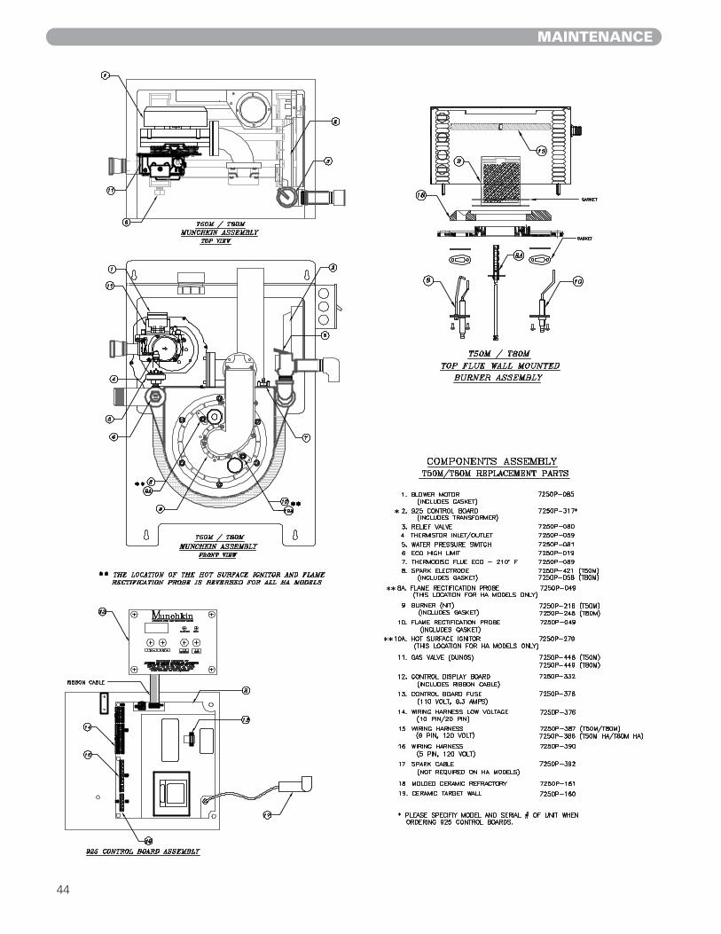
MAINTENANCE
44

MAINTENANCE
45
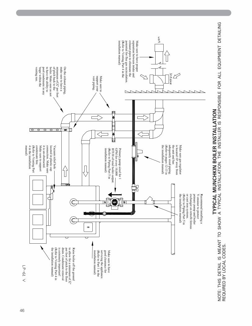
46
TY
PIC
AL
MU
NC
HK
IN B
OIL
ER IN
STA
LLA
TIO
NN
OT
E:
TH
IS D
ETA
IL I
S M
EA
NT
TO
SH
OW
A T
YP
ICA
L IN
STA
LLA
TIO
N.
TH
E I
NS
TALL
ER
IS
RE
SP
ON
SIB
LE F
OR
ALL
EQ
UIP
ME
NT
DE
TAIL
ING
RE
QU
IRE
D B
Y L
OC
AL
CO
DE
S.
47
Installation Checklist for Munchkin Boilers
Questions relating to electrical1. Is there continuous 120 volts line voltage supplied to the unit?2. Is the line power properly polarized? (Black wire is “hot” lead)3. Is there and adequate ground supplied to the heater?4. Are we correctly using the supplied wires to power the pumps? (No shared neutrals)
Questions relating to gas1. Is there continuous 120 volts line voltage supplied to the unit?2. Is the unit set up for the correct gas type? (Propane or Natural Gas)3. Is the boiler properly labeled for fuel type?4. Do we have minimum ¾” ID pipe brought to the unit? (1¼” for 399M models)5. Is the entire gas piping sized adequately, including additional appliances and same gas
line?6. Is the regulator sized properly with an adequate distance away from the appliance?7. Do we have 7” W.C. when the boiler is running?8. Does the gas pressure stay below 14” W.C.?9. Is the pressure drop between static pressure (nothing running) and dynamic pressure
(unit running) less than 2” W.C.?
Questions relating to venting1. Is all the exhaust piping pitched back to the unit at a minimum of ¼” per foot with no
areas for condensate to pool?2. Is concentric vent kit glued properly?3. Is all venting supported?4. Does exhaust vent into an open area, away from inside corners, building air intakes etc?5. Does exhaust stay clear of intake piping and have enough separation as not to re-circu-
late flue gas?
Questions relating to condensate management1. Would elevating the boiler off of the floor help the condensate run?2. Does the condensate line slope to the drain at a minimum of ¼” per foot?3. Is the condensate pump installed properly?4. Does the condensate line have an air relief? Is the hole, located in the terminating nipple,
free and clear?5. Is the condensate line free of kinks?6. Can the condensate line potentially freeze?7. Is the condensate line sized properly for multiple heaters?
Questions relating to piping1. Is the primary pump appropriately sized to handle the boilers 1 GPM per 10,000 BTUH
total boiler output, regardless of BTU zone requirements? 2. Have you taken into consideration the pressure drop of the vessel, the indirect coil, or
the normal piping restrictions when sizing your pumps?3. If installing the boiler in an existing application, is there a strainer installed to protect the
boiler from scale and particulates?4. Did we flush out and purge the system? Is the strainer free and clear upon leaving the
jobsite?5. Are you following the correct suggested piping installation drawing?
(Vision I installation -vs.- standard installation)
Questions relating to Glycol/antifreezeDid we account for possible losses in our heat transfer rate or increased head pressures when
using the boiler with an antifreeze solution?

SuperStor Ultra, SuperStor, Voyager, Voyager Sanitizer, and Everlast are registered trademarks of Heat Transfer Products, Inc.Munchkin R1
© 2006, 2005, 2004 Heat Transfer Products, Inc. LP-61 REV. 4/1/06