murata power solutions lss-t/10-w12 datasheet · distributed bus architectures (dba) ... dynamic...
TRANSCRIPT

FEATURESnVertical SIP-mount small footprint package
nOutput from 0.6 to 6 Volts up to 51 Watts
nUltra-wide 4.5 to 13.8 Vdc input range
nOutstanding thermal performance and derating
nExtensive self-protection and short circuit features with no output reverse conduction
nOn/Off control and trim functions
nHigh efficiency up to 93% with no heatsink
nFully protected against temperature and voltage limits
nDesigned to meet UL/IEC/EN60950-1 safety approvals
Fabricated on a Single Inline Package (SIP) module, the LSS-T/10-W12 series is a miniature non-iso-lated Point-of-Load (POL) switching DC/DC power converter for embedded applications. The converter offers both tight regulation and high efficiency directly at the power usage site. Typically, no extra outside components are required. The module mounts vertically, occupying a tiny board footprint. The upright mounting improves cooling airflow. Suggested applications include powering CPU’s, distributed bus architectures (DBA) with a master bus power supply, programmable logic and mixed voltage systems.
Based on synchronous buck converter topology, the extraordinary efficiency means very low heat and little electrical noise. The ultra wide input range is 4.5 to 13.8 Volts. Additional features include quick transient response to step loads and
stable no-load operation. A key feature is select-able output voltage either by precision resistor, trim pot or user’s voltage input. The output range is adjustable from 0.6 to 6 Vdc.
A wealth of protection features prevents damage to both the converter and outside circuits. Inputs are protected from undervoltage and outputs offer short circuit protection, overcurrent and excess temperature shut down. The unit is designed to meet all EMI/RFI certifications as well as HALT reliability. RoHS6 hazardous material compliance is specified as standard. All units are precision assembled in a highly automated computer-controlled surface mount facility with ISO-traceable manufacturing quality standards. Additional system functions include a remote On/Off control.
PRODUCT OVERVIEW
Simplified Block Diagram
+VIN
PWMController
SignalConditioning
OT
On/OffControl
Common
Trim
Common
+VOUT
Typical topology is shown.
Figure 1. LSS-T/10-W12 Series, 10 Amp Model
LSS-T/10-W12Adjustable Output 10 Amp SIP-mount DC/DC Converter
MDC_MDC_LSS-T10-W12.C01 Page 1 of 8
www.murata-ps.com
www.murata-ps.com/support
For full details go towww.murata-ps.com/rohs

➀Dimensions are in inches (mm).➁ All specifications are at nominal line voltage, Vout = 5V and full load, +25 °C unless otherwise
noted. See detailed specifications. Output capacitors are 2 x 0.47 µF ceramic. Input cap is 22 µF.
I/O caps are necessary for our test equipment and may not be needed for your application.➂Vin must be 2V or higher than Vout for 3.3 to 5V outputs.
ORDERING GUIDE
Root Model ➁
Output Input
Efficiency
Package
Vout (Volts)
Iout
(Amps max)
Power(Watts)
R/N (mVp-p)➁ Regulation (Max.)➂Vin Nom. (Volts)
Range (Volts)
Iin, no load
(mA)
Iin, full load (Amps) Case C72 ➀ PinoutTyp. Max. Line Load Min. Typ.
LSS-T/10-W12 0.591 – 6 10 60 45 75 ±0.2% ±1.4% 12 4.5 – 13.8 80 4.48 91.5 930.41 × 0.65 × 0.4
(10.4 × 16.5 × 10.2) P73
Performance Specifications and Ordering Guide ➁
Output Configuration: L = Unipolar Low Voltage
Maximum Rated Output Current in Amps
Non-Isolated SIP
Output Voltage Range T = Trimmable, 0.6 – 6 Volts Wide Input Voltage Range
W12 = 4.5 – 13.8 Volts (10Amp)
L SS - / W12-T 10 C-
RoHS Hazardous Substance Compliance C = RoHS6 (does not claim EU RoHS exemption 7b–lead in solder)
PART NUMBER STRUCTURE
MECHANICAL SPECIFICATIONS
0.41(10.4)
0.65(16.5)
0.05(1.3)
.032 (0.8) ±.002 OR
.025 (0.6) ±.002 TYP
0.24 MAX(6.1)
0.06 REF THK(1.5)
0.38 MAX(9.7)
0.12 (3.0)
0.067 (1.7)
0.067 (1.7)
0.134 (3.4)
0.134 (3.4)
0.205 REF(5.2)
INPUT/OUTPUT CONNECTIONS LSS-T/10-W12
Pin Function P731 Enable On/Off2 +Vin
3 Ground4 +Vout
5 Output Trim
Figure 2 . LSS-T/10-W12 SeriesComponent locations are typical.
LSS-T/10-W12Adjustable Output 10 Amp SIP-mount DC/DC Converter
MDC_MDC_LSS-T10-W12.C01 Page 2 of 8
www.murata-ps.com/support
Third Angle Projection
Dimensions are in inches (mm) shown for ref. only.
Components are shown for reference only.
Tolerances (unless otherwise specified):.XX ± 0.02 (0.5).XXX ± 0.010 (0.25)Angles ± 2˚

Input
Input Voltage Range See Ordering Guide. See note 19.
Recommended External Fuse 20 Amps
Isolation Not isolated. The input and output commons internally connected.
Start-up Voltage 4.2 Volts
Undervoltage Shutdown 3.4 Volts
Overvoltage Shutdown None
Reflected (Back) Ripple Current 20 mA pk-pk
Internal Input Filter Type Capacitive
Reverse Polarity Protection1(Note 15) See fuse information
Input Current: Full Load Conditions See Ordering Guide Inrush Transient 0.4 A2 sec Shutdown mode (Off, UV, OT) 5 mA Output Short-Circuit 60 mA No load, 5Vout 80 mA Low Line (Vin = Vmin, 5Vout) 11.95 AmpsRemote On/Off Control (Note 5) (LSS-T/10-W12, no suffix) Positive Logic On = +1.5 V to plus Vin max. or open pin Off = 0 to +0.2 V max. or ground pin Current 1 mA
Output
Minimum Loading (Note 7) No minimum load
Maximum Output Power 51 Watts (Note 11)
Accuracy (50% load) ±1.5% of V setting
Voltage Adjustment Range (Notes 13, 19) See Ordering Guide
Temperature Coefficient ±0.02% max. per °C of Vout range
Ripple/Noise (20MHz bandwidth) See Ordering Guide and Note 8
Line Load Regulation (See Tech Notes) See Ordering Guide and Note 10
Efficiency See Ordering GuideMaximum Capacitive Loading Cap-ESR = 0.001 to 0.01 Ω 5,000 µF Cap-ESR > 0.01 Ω 10,000 µF
Current Limit Inception (98% of Vout setting) (Note 12) 33 Amps (after warm up) Short Circuit Mode (Note 6, 12) Short Circuit Current Output 0.6 Amp Protection Method Hiccup autorecovery upon overload removal. (Note 16) Short Circuit Duration Continuous, no damage (output shorted to ground)
Performance/Functional SpecificationsAll specifications are typical unless noted See Note 1.
Dynamic Characteristics
Dynamic Load Response 20 µSec to within ±2% of final value (0 to 50% load step, di/dt = 10A/µSec, no external caps)
Turn-On Time 6 mSec for Vout regulated
Remote On/Off Time 6 mSec for Vout regulated
Switching Frequency 600 kHz
Environmental
Calculated MTBF (Note 4) TBC
Operating Temperature Range –45 to +85°C (Note 9) With Derating See Derating Curves (Note 18)
Storage Temperature Range –55 to +125°C
Thermal Protection Shutdown +115°C
Relative Humidity 85%/+85°C
Physical
Outline Dimensions See Mechanical Specifications
Weight 0.07 ounces (2 grams)
Electromagnetic Interference Designed to meet FCC Part 15, EN55022, (may require external filter) conducted and radiated
Safety Designed to meet UL/cUL 60950-1, CSA-C22.2 No. 60950-1, IEC/EN 60950-1
Absolute Maximum Ratings
Input Voltage Continuous or transient 15 Volts max.
Output Power 51 Watts max.
On/Off Control 0V. min to +Vin max.
Input Reverse-Polarity Protection See Fuse section
Output Current Current limited. Devices can withstand sustained output short circuits without damage.
Storage Temperature –40 to +125°C
Lead Temperature See soldering guidelines
Absolute maximums are stress ratings. Exposure of devices to greater than any of these conditions may adversely affect long-term reliability. Proper operation under conditions other than those listed in the Performance/Functional Specifications Table is not implied nor recommended.
CAUTION: This product is not internally fused. To comply with safety agency certifications and to avoid injury to personnel or equipment, the user must supply an external fast-blow fuse to the input terminals. See fuse information.
LSS-T/10-W12Adjustable Output 10 Amp SIP-mount DC/DC Converter
MDC_MDC_LSS-T10-W12.C01 Page 3 of 8
www.murata-ps.com/support

Trim Connections
RTRIM
RLOADTrim
+VOUT
Ground
RTRIM (kΩ) = 1.182 VOUT − 0.591
Note: To avoid output overvoltage shutdown,trim must always be connected.
Do not exceed maximum output power when adjusting trim.
LSS-T/10-W12
(1) All models are tested and specified with external 1||10 μF ceramic/tantalum output capacitors and a 22 μF external input capacitor. All capacitors are low ESR types. These capacitors are necessary to accommodate our test equipment and may not be required to achieve specified performance in your applications. All models are stable and regulate within spec under no-load conditions.
All specifications are typical unless noted. General conditions for Specifications are +25 °C, Vin=nominal, Vout=5V, full load. Adequate airflow must be supplied for extended testing under power.
(2) Input Ripple Current is tested and specified over a 5 Hz to 20 MHz bandwidth. Input filter-ing is Cin=2 × 100 μF, 100V tantalum, Cbus=1000 μF, 100V electrolytic, Lbus=1 μH.
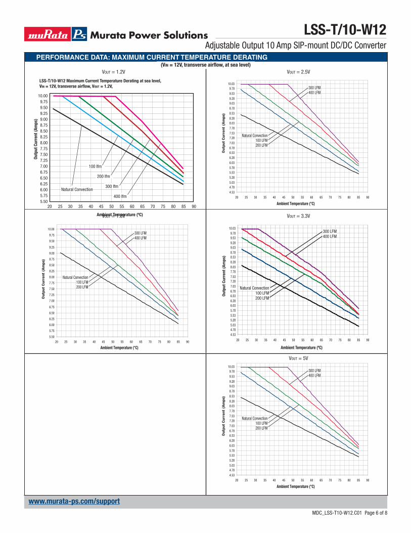
(3) Note that Maximum Power Derating curves indicate an average current at nominal input voltage. At higher temperatures and/or lower airflow, the DC/DC converter will tolerate brief full current outputs if the total RMS current over time does not exceed the Derating curve. All Derating curves are presented at sea level altitude. Be aware of reduced power dissipation with increasing density altitude.
(4) Mean Time Before Failure is calculated using the Telcordia (Belcore) SR-332 Method 1, Case 3, ground fixed conditions, Tpcboard=+25°C, full output load, natural air convec-tion.
(5) The On/Off Control is normally controlled by a switch or open collector or open drain tran-sistor. But it may also be driven with external logic or by applying appropriate external voltages which are referenced to Input Common.
(6) Short circuit shutdown begins when the output voltage degrades approximately 2% from the selected setting.
(7) The outputs are not intended to sink appreciable reverse current. This may damage the outputs.
(8) Output noise may be further reduced by adding an external filter. See I/O Filtering and Noise Reduction. Use only as much output filtering as needed and no more. Larger caps may slow transient response or degrade dynamic performance. Thoroughly test your system under full load, especially with low-ESR ceramic capacitors.
(9) All models are fully operational and meet published specifications, including “cold start” at –40°C.
(10) Regulation specifications describe the deviation as the line input voltage or output load current is varied from a nominal midpoint value to either extreme.
(11) For the LSS-T/10-W12, the maximum rated output power is 51 Watts (5.1 Volts and 10 Amps). Output adjustment up to 6 Volts must reduce current to remain within the 51 Watt output limit.
(12) Output current limit and short circuit protection is non-latching. When the overcurrent fault is removed, the converter will immediately recover.
(13) Do not exceed maximum power specifications when adjusting the output trim.
(14) At zero output current, the output may contain low frequency components which exceed the ripple specification. The output may be operated indefinitely with no load.
(15) Input Fusing: If reverse polarity is accidentally applied to the input, a body diode will become forward biased and will conduct considerable current. To ensure reverse input protection with full output load, always connect an external input fast-blow fuse in series with the +Vin input. Use approximately twice the full input current rating with nominal input voltage.
(16) “Hiccup” overcurrent operation repeatedly attempts to restart the converter with a brief, full-current output. If the overcurrent condition still exists, the restart current will be removed and then tried again. This short current pulse prevents overheating and damag-ing the converter. Once the fault is removed, the converter immediately recovers normal operation.
(17) Output accuracy is dependent on user-supplied trim resistors. To achieve high accuracy, use ±1% or better tolerance metal-film resistors.
(18) At full power, on-board component package temperatures must not exceed +128°C.
(19) Vin must be 2 Volts or higher than Vout for +3.3 to +5V outputs.
Notes
Soldering Guidelines
Murata Power Solutions recommends the specifications below when installing these converters. These specifications vary depending on the solder type. Exceeding these specifica-tions may cause damage to the product. Be cautious when there is high atmospheric humidity. We strongly recommend a mild pre-bake (100° C. for 30 minutes). Your production
environment may differ; therefore please thoroughly review these guidelines with your process engineers.
Wave Solder Operations for through-hole mounted products (THMT)
For Sn/Ag/Cu based solders: For Sn/Pb based solders:
Maximum Preheat Temperature 115° C. Maximum Preheat Temperature 105° C.
Maximum Pot Temperature 270° C. Maximum Pot Temperature 250° C.
Maximum Solder Dwell Time 7 seconds Maximum Solder Dwell Time 6 seconds
LSS-T/10-W12Adjustable Output 10 Amp SIP-mount DC/DC Converter
MDC_MDC_LSS-T10-W12.C01 Page 4 of 8
www.murata-ps.com/support

LSS-T/10-W12Adjustable Output 10 Amp SIP-mount DC/DC Converter
MDC_MDC_LSS-T10-W12.C01 Page 5 of 8
www.murata-ps.com/support
PERFORMANCE DATA: EFFICIENCY VS LINE VOLTAGE AND LOAD CURRENT
Vout = 1.2VTa = +25°C
LSS-T/10-W12Efficiency vs. Line Voltage and Load Current @ 25°C (VOUT = 1.2V)92
90
88
86
84
82
80
76
74
72
70
78
681 2 3 4 5 6 7 8 9 10
Load Current (Amps)
Effic
ienc
y (%
)
VIN = 4.5V
VIN = 12V
VIN = 14V
Vout = 3.3V
1A 2A 3A 4A 5A 6A 7A 8A 9A 10A
Load Current (Amps)
76%
78%
80%
82%
84%
86%
88%
90%
92%
94%
96%
98%
Effic
ienc
y (%
)
VIN = 14 V
VIN = 12 V
VIN = 4.5 V
Vout = 1.8V
72%
74%
76%
78%
80%
82%
84%
86%
88%
90%
92%
94%
96%
1A 2A 3A 4A 5A 6A 7A 8A 9A 10A
Load Current (Amps)
Effi
cien
cy (
%)
VIN = 14 V
VIN = 12 V
VIN = 4.5 V
Vout = 5V
78%
80%
82%
84%
86%
88%
90%
92%
94%
96%
98%
100%
1A 2A 3A 4A 5A 6A 7A 8A 9A 10A
Load Current (Amps)
Effi
cien
cy (
%)
VIN = 14 V
VIN = 12 V
VIN = 7 V
Vout = 6V
1A 2A 3A 4A 5A 6A 7A 8A 9A 10A
Load Current (Amps)
78%
80%
82%
84%
86%
88%
90%
92%
94%
96%
98%
100%
Effic
ienc
y (%
)
VIN = 14 V
VIN = 12 V
VIN = 7 V
LSS-T/10-W12Adjustable Output 10 Amp SIP-mount DC/DC Converter
MDC_MDC_LSS-T10-W12.C01 Page 6 of 8
www.murata-ps.com/support
PERFORMANCE DATA: MAXIMUM CURRENT TEMPERATURE DERATING
Vout = 1.2V(Vin = 12V, transverse airflow, at sea level)
Vout = 2.5V
20 25 30 35 40 45 50 55 60 65 70 75 80 85 90
4.53
4.785.03
5.28
5.535.78
6.03
6.28
6.536.78
7.03
7.287.53
7.78
8.038.28
8.53
8.78
9.039.28
9.53
9.7810.03
Ambient Temperature (°C)
Out
put
Cur
rent
(A
mps
)
Natural Convection100 LFM200 LFM
300 LFM400 LFM
Vout = 1.8V
20 25 30 35 40 45 50 55 60 65 70 75 80 85 90
5.50
5.75
6.00
6.25
6.50
6.75
7.00
7.25
7.50
7.75
8.00
8.25
8.50
8.75
9.00
9.25
9.50
9.75
10.00
Ambient Temperature (°C)
Out
put
Cur
rent
(A
mps
)
Natural Convection100 LFM200 LFM
300 LFM400 LFM
Vout = 3.3V
Natural Convection100 LFM200 LFM
300 LFM400 LFM
Ambient Temperature (ºC)
Out
put
Cur
rent
(A
mps
)
20 25 30 35 40 45 50 55 60 65 70 75 80 85 90
4.534.785.035.285.535.786.036.286.536.787.037.287.537.788.038.288.538.789.039.289.539.78
10.03
Vout = 5V
20 25 30 35 40 45 50 55 60 65 70 75 80 85 90
4.53
4.785.03
5.28
5.535.78
6.03
6.28
6.536.78
7.03
7.287.53
7.78
8.038.28
8.53
8.78
9.039.28
9.53
9.7810.03
Ambient Temperature (°C)
Out
put
Cur
rent
(A
mps
)
Natural Convection100 LFM200 LFM
300 LFM400 LFM
LSS-T/10-W12 Maximum Current Temperature Derating at sea level, VIN = 12V, transverse airflow, VOUT = 1.2V,
20
7.507.758.00
6.756.50
7.00
6.006.25
5.755.50
7.25
8.258.508.759.009.259.509.75
10.00
30 40 753525 705045 60 6555 908580
Ambient Temperature (ºC)
Outp
ut C
urre
nt (A
mps
)
100 lfm
200 lfm
300 lfm
400 lfm
Natural Convection

LSS-T/10-W12Adjustable Output 10 Amp SIP-mount DC/DC Converter
MDC_MDC_LSS-T10-W12.C01 Page 7 of 8
www.murata-ps.com/support
PERFORMANCE DATA: OUTPUT RIPPLE AND NOISE (PARD)
Vout = 1.2VVin = 12V
Vout = 3.3V
Vout = 1.8V Vout = 5V
Vout = 6VVout = 2.5V

LSS-T/10-W12Adjustable Output 10 Amp SIP-mount DC/DC Converter
MDC_MDC_LSS-T10-W12.C01 Page 8 of 8
www.murata-ps.com/support
Murata Power Solutions, Inc. makes no representation that the use of its products in the circuits described herein, or the use of other technical information contained herein, will not infringe upon existing or future patent rights. The descriptions contained herein do not imply the granting of licenses to make, use, or sell equipment constructed in accordance therewith. Specifications are subject to change without notice. © 2017 Murata Power Solutions, Inc.
Murata Power Solutions, Inc. 11 Cabot Boulevard, Mansfield, MA 02048-1151 U.S.A.ISO 9001 and 14001 REGISTERED
This product is subject to the following operating requirements and the Life and Safety Critical Application Sales Policy: Refer to: http://www.murata-ps.com/requirements/
PERFORMANCE DATA: TURN-ON, TURN-OFF TIMES
On/Off EnableVin = 12V
Vin Power On
On/Off Disable Vin Power Off