murata products global part numbering - anglia c · murata products global part numbering for...
TRANSCRIPT

MURATA PRODUCTSGlobal Part Numbering
For safety, you are requested to approve our product specification or transact the approval sheet for product specifications before ordering. K23E5.pdf 01.11.16

For safety, you are requested to approve our product specification or transact the approval sheet for product specifications before ordering. K23E5.pdf 01.11.16
As typified by the prevalence of business innovations such as Supply Chain Management andE-commerce, business environments are undergoing remarkable changes these days.At Murata, we consider adapting to our customer's EDP systems to be an urgent task. That iswhy we are committed to building global systems for order-receiving and production. As part ofthis effort, Murata has established a new part numbering system that is rationalized, systematicand, most importantly, globally unified. This brochure is designed to provide our valuedcustomers with an explanation of the structure of our global part numbering system that havebeen adopted since June 2001. It includes a table that explains the meaning of codes for mostMurata product categories. Please take a minute to read through and study the brochure.Please note that you can easily translate between current part numbers and their correspondingnew global equivalents using our Internet Search Engine (http://www.murata.co.jp/search/) orthe latest version (2.43) of our "2002 Murata Products" CD-ROM.If you have any questions related to our new global part numbering system, please feel free tocontact your Murata sales office, sales representative or distributor.

For safety, you are requested to approve our product specification or transact the approval sheet for product specifications before ordering. K23E5.pdf 01.11.16
CapacitorsChip Monolithic Ceramic Capacitors • • • • • • • • • • • • • • • • • • • • • • • • • 2-4Monolithic Ceramic Capacitors (lead type)• • • • • • • • • • • • • • • • • • • 5-6Ceramic Capacitors (12V-500V) • • • • • • • • • • • • • • • • • • • • • • • • • • • • • • • • 7High Voltage Ceramic Capacitors (250V-6.3kV)• • • • • • • • • • • • • • • 8Safety Standard Recognized Ceramic Capacitors• • • • • • • • • • • • • • 9High-voltage Ceramic Capacitors (over 10kV) • • • • • • • • • • • • • • • 10High-frequency Power Ceramic Capacitors• • • • • • • • • • • • • • • • • • • 11Ceramic Trimmer Capacitors • • • • • • • • • • • • • • • • • • • • • • • • • • • • • • • • • • 12C Networks (Bulk) • • • • • • • • • • • • • • • • • • • • • • • • • • • • • • • • • • • • • • • • • • • • • • 13C Networks (Small Taping Type) • • • • • • • • • • • • • • • • • • • • • • • • • • • • • • 13
Resistors/ThermistorsPTC Thermistors (POSISTORr) for Heater • • • • • • • • • • • • • • • • • • • • • 14PTC Thermistors (POSISTORr) for Circuit Protection • • • • • • • • • 14PTC Thermistors (POSISTORr) for Circuit Protection SMD Type • 15PTC Thermistors (POSISTORr) for Overheat Sensing Chip Type • 15PTC Thermistors (POSISTORr) for Circuit Protection /
for Overheat Sensing Lead Type• • • • • • • • • • • • • • • • • • • • • • • • • • • 16PTC Thermistors (POSISTORr) for Motor Starters• • • • • • • • • • • • • 17PTC Thermistors (POSISTORr) for Motor Starter Plug-on Type• • 17PTC Thermistors (POSISTORr) for Degaussing Circuits• • • • • • • 18NTC Thermistors for Temperature Compensation Chip Type• 19NTC Thermistors for Temperature Sensor Lead Type • • • • • • • • • 20NTC Thermistors for Inrush Current Suppression • • • • • • • • • • • • • 20High-voltage Resistors • • • • • • • • • • • • • • • • • • • • • • • • • • • • • • • • • • • • • • • • • 21R Network • • • • • • • • • • • • • • • • • • • • • • • • • • • • • • • • • • • • • • • • • • • • • • • • • • • • • •22Trimmer Potentiometers • • • • • • • • • • • • • • • • • • • • • • • • • • • • • • • • • • • • • • • • 23
Coils/Delay LinesChip Coils (SMD) • • • • • • • • • • • • • • • • • • • • • • • • • • • • • • • • • • • • • • • • • • • • 24-25Chip Multilayer Delay Lines• • • • • • • • • • • • • • • • • • • • • • • • • • • • • • • • • • • • 25
Noise Suppression Products/(EMIFILr)Chip EMIFILr Inductor Type• • • • • • • • • • • • • • • • • • • • • • • • • • • • • • • • • • • • 26Chip EMIFILr Capacitor Type • • • • • • • • • • • • • • • • • • • • • • • • • • • • • • • • • • 27Chip EMIFILr Capacitor Array Type• • • • • • • • • • • • • • • • • • • • • • • • • • • 28Chip EMIFILr LC Combined Type • • • • • • • • • • • • • • • • • • • • • • • • • • • • • • 29Chip EMIFILr RC Combined Type• • • • • • • • • • • • • • • • • • • • • • • • • • • • • • 30Chip EMIFILr RC Combined Array Type • • • • • • • • • • • • • • • • • • • • • • 30Chip EMIFILr Common Mode Choke Coils • • • • • • • • • • • • • • • • • • • • 31Lead Type EMIFILr Inductor Type• • • • • • • • • • • • • • • • • • • • • • • • • • • • • 32Lead Type EMIFILr Capacitor Type• • • • • • • • • • • • • • • • • • • • • • • • • • • • 33Lead Type Common Mode Choke Coils / AC Line Filters • • • • 34Chip Varistors • • • • • • • • • • • • • • • • • • • • • • • • • • • • • • • • • • • • • • • • • • • • • • • • • • 35Chip EMIGUARDr (EMIFILr with Varistor Function) • • • • • • • • • • 35Lead Type EMIGUARDr (EMIFILr with Varistor Function) • • • • • 36RC/C Module • • • • • • • • • • • • • • • • • • • • • • • • • • • • • • • • • • • • • • • • • • • • • • • • • • • 37Ferrite Cores • • • • • • • • • • • • • • • • • • • • • • • • • • • • • • • • • • • • • • • • • • • • • • • • • • • • 38
ResonatorsCERALOCKr (MHz) • • • • • • • • • • • • • • • • • • • • • • • • • • • • • • • • • • • • • • • • • • • • • 39CERALOCKr (kHz)• • • • • • • • • • • • • • • • • • • • • • • • • • • • • • • • • • • • • • • • • • • • • • 39SAW Resonators• • • • • • • • • • • • • • • • • • • • • • • • • • • • • • • • • • • • • • • • • • • • • • • • 40BGS Resonators • • • • • • • • • • • • • • • • • • • • • • • • • • • • • • • • • • • • • • • • • • • • • • • • 40
Piezoelectric Sound ComponentsPiezoelectric Speakers (CERAMITONEr ) • • • • • • • • • • • • • • • • • • • • • 41Piezoelectric Diaphragms • • • • • • • • • • • • • • • • • • • • • • • • • • • • • • • • • • • • • • 41Piezoelectric Sounders/Piezoelectric Buzzers /Piezoelectric Ringers(PIEZORINGERr)• • • • • • • • • • • • • • • • • • • • • • • • • 42SMD Piezoelectric Sounder • • • • • • • • • • • • • • • • • • • • • • • • • • • • • • • • • • • • 42SMD Piezoelectric Receiver • • • • • • • • • • • • • • • • • • • • • • • • • • • • • • • • • • • • 43
Filters for Communication EquipmentAntenna/Duplexer Dielectric Filters (GIGAFILr)for RF/Local Dielectric Filters (GIGAFILr) • • • • • • • • • • • • • • • • • • • • • 44Chip Multilayer LC Filters for RF/Local and IF • • • • • • • • • • • • • • • • 44SAW Filters for RF/Local and IF • • • • • • • • • • • • • • • • • • • • • • • • • • • • • • • 45Ceramic Filters (CERAFILr) for IF • • • • • • • • • • • • • • • • • • • • • • • • • • • • • • 45BGS Filter for IF• • • • • • • • • • • • • • • • • • • • • • • • • • • • • • • • • • • • • • • • • • • • • • • • • 46Ceramic Discriminators for IF • • • • • • • • • • • • • • • • • • • • • • • • • • • • • • • • • • 46
Microwave ComponentsIsolators • • • • • • • • • • • • • • • • • • • • • • • • • • • • • • • • • • • • • • • • • • • • • • • • • • • • • • • • •47Chip Multilayer Hybrid Couplers/Chip Multilayer Hybrid Dividers• 47Chip Multilayer Hybrid Baluns• • • • • • • • • • • • • • • • • • • • • • • • • • • • • • • • • 48Chip Dielectric Antennas • • • • • • • • • • • • • • • • • • • • • • • • • • • • • • • • • • • • • • • 48Dielectric Resonators (RESOMICSr) TE Mode • • • • • • • • • • • • • • • • • 49Dielectric Resonators (RESOMICSr) TEM Mode • • • • • • • • • • • • • • • 50High-Frequency Microchip Capacitors • • • • • • • • • • • • • • • • • • • • • • • • 51Coaxial Connectors (Chip Type Receptacle)• • • • • • • • • • • • • • • • • • • 52Coaxial Connectors (with Cable) • • • • • • • • • • • • • • • • • • • • • • • • • • • • • • 52
Microwave ModulesRF Diode Switches • • • • • • • • • • • • • • • • • • • • • • • • • • • • • • • • • • • • • • • • • • • • • • 53VCO • • • • • • • • • • • • • • • • • • • • • • • • • • • • • • • • • • • • • • • • • • • • • • • • • • • • • • • • • • • • •53PLL Modules• • • • • • • • • • • • • • • • • • • • • • • • • • • • • • • • • • • • • • • • • • • • • • • • • • • • • 53
Filters for Audio Visual EquipmentCERAFILr for AM • • • • • • • • • • • • • • • • • • • • • • • • • • • • • • • • • • • • • • • • • • • • • • • 54CERAFILr for Search-stop Signal Detection • • • • • • • • • • • • • • • • • • • 54CERAFILr for FM • • • • • • • • • • • • • • • • • • • • • • • • • • • • • • • • • • • • • • • • • • • • • • • 55Discriminators for FM • • • • • • • • • • • • • • • • • • • • • • • • • • • • • • • • • • • • • • • • • • 55CERAFILr for TV/VCR • • • • • • • • • • • • • • • • • • • • • • • • • • • • • • • • • • • • • • • • • • 56Discriminators for TV/VCR• • • • • • • • • • • • • • • • • • • • • • • • • • • • • • • • • • • • • 56Ceramic Traps • • • • • • • • • • • • • • • • • • • • • • • • • • • • • • • • • • • • • • • • • • • • • • • • • • 57BGS Traps• • • • • • • • • • • • • • • • • • • • • • • • • • • • • • • • • • • • • • • • • • • • • • • • • • • • • • •57SAW Filters for TV/VCR/Digital Broadcasting• • • • • • • • • • • • • • • • 58SAW Filters for TV/VCR Dual Type• • • • • • • • • • • • • • • • • • • • • • • • • • • • 58BGS Filters • • • • • • • • • • • • • • • • • • • • • • • • • • • • • • • • • • • • • • • • • • • • • • • • • • • • • •59
Products for Video EquipmentFocus Adjustment Resistors • • • • • • • • • • • • • • • • • • • • • • • • • • • • • • • • • • • • 60
SensorsPTC Thermistors (POSISTORr) Chip Type • • • • • • • • • • • • • • • • • • • • • 61PTC Thermistors (POSISTORr) Lead Type • • • • • • • • • • • • • • • • • • • • • 61NTC Thermistors Lead Type • • • • • • • • • • • • • • • • • • • • • • • • • • • • • • • • • • • • 62Pyroelectric Infrared Sensors • • • • • • • • • • • • • • • • • • • • • • • • • • • • • • • • • • 62Pyroelectric Infrared Sensor Modules • • • • • • • • • • • • • • • • • • • • • • • • • 62Ultrasonic Sensors• • • • • • • • • • • • • • • • • • • • • • • • • • • • • • • • • • • • • • • • • • • • • • 62Shock Sensors • • • • • • • • • • • • • • • • • • • • • • • • • • • • • • • • • • • • • • • • • • • • • • • • • • 63Built-in Circuit Acceleration Sensors • • • • • • • • • • • • • • • • • • • • • • • • • • • 63Piezoelectric Gyroscopes (GYROSTARr) • • • • • • • • • • • • • • • • • • • • • • 63Non-contact Potentiometers • • • • • • • • • • • • • • • • • • • • • • • • • • • • • • • • • • • 63Rotary Sensors • • • • • • • • • • • • • • • • • • • • • • • • • • • • • • • • • • • • • • • • • • • • • • • • • 63Magnetic Pattern Recognition Sensors • • • • • • • • • • • • • • • • • • • • • • • • 63Electric Potential Sensors• • • • • • • • • • • • • • • • • • • • • • • • • • • • • • • • • • • • • • • 63
CONTENTS
Recycled Paper

For safety, you are requested to approve our product specification or transact the approval sheet for product specifications before ordering. K23E5.pdf 01.11.16
CapacitorsCapacitors
2
(Global Part Number)
w
qProduct ID
wSeries
Chip Monolithic Ceramic Capacitors
GR
ER
GQ
GM
GN
LL
GJ
GA
M
P
F
H
A
D
M
A
M
L
6
2
2
3
Tin Plated layer
Soldering Electrode
High-frequency andhigh-power Type
High-frequency and high-power Type (Ribbon Terminal)
High-frequency Type
High-frequency Type(Ribbon Terminal)
High-frequency forFlow/Reflow Soldering
Monolithic Microchip
Capacitor Array
Low ESL Wide-width Type
Low Dissipation
Smoothing Type
for AC250V (r.m.s.)
Safety Standard Recognized Type
Product ID Code Series
GR
q
M
e
18
r
8
t
B1
y
1H
u
102
i
K
o
A01
With the array type GNM series, "Dimension(T)" indicates the number of elements.
eDimension (LgW)
!0
K
Code
0.6g0.3 mm
0.5g0.5 mm
0.8g0.8 mm
1.25g1.0 mm
1.0g0.5 mm
1.6g0.8 mm
2.0g1.25 mm
2.8g2.8 mm
3.2g1.6 mm
3.2g2.5 mm
4.5g2.0 mm
4.5g3.2 mm
5.7g2.8 mm
5.7g5.0 mm
Dimension (LgW)
0201
0202
0303
0504
0402
0603
0805
1111
1206
1210
1808
1812
2211
2220
EIA
03
05
08
11
15
18
1X
21
22
31
32
3X
42
43
52
55
A
B
C
D
E
M
N
R
Q
X
1.0 mm
1.25 mm
1.6 mm
2.0 mm
2.5 mm
1.15 mm
1.35 mm
1.8 mm
1.5 mm
Depends on individual standards.
rDimension (T)
Code
3
4
5
6
7
8
9
0.3 mm
4-elements (Array Type)
0.5 mm
0.6 mm
0.7 mm
0.8 mm
0.85 mm
Dimension (T)
Depends on individual standards.
Depends on individual standards.
Continued on the following page.
o Part Numbering
tTemperature Characteristics
Code
20 to 85°C
-55 to 125°C
-55 to 125°C
-55 to 85°C
-55 to 85°C
-55 to 85°C
TemperatureRange
+350 to -1000ppm/°C
0±30ppm/°C
0±60ppm/°C
-150±60ppm/°C
-220±60ppm/°C
-330±60ppm/°C
Capacitance Change or Temperature Coefficient
SL
C0G
C0H
P2H
R2H
S2H
TemperatureCharacteristics
1X
5C
6C
6P
6R
6S
-55 to 125°C
-55 to 125°C
-55 to 125°C
-55 to 125°C
-55 to 125°C
-55 to 125°C
Operating Temperature Range

For safety, you are requested to approve our product specification or transact the approval sheet for product specifications before ordering. K23E5.pdf 01.11.16
CapacitorsCapacitors
3
yRated Voltage
0J
1A
1C
1E
1H
2A
2D
2E
YD
2H
2J
3A
3D
3F
E2
GB
GC
GD
GF
DC6.3V
DC10V
DC16V
DC25V
DC50V
DC100V
DC200V
DC250V
DC300V
DC500V
DC630V
DC1kV
DC2kV
DC3.15kV
AC250V
X2; AC250V (Safety Standard Recognized Type GB)
X1, Y2; AC250V (Safety Standard Recognized Type GC)
Y3; AC250V (Safety Standard Recognized Type GD)
Y2; AC250V (Safety Standard Recognized Type GF)
Code Rated Voltage
uCapacitance
Expressed by three figures. The unit is pico-farad(pF). The first and second figures are significant digits, and the third figure expresses the number of zeros which follow the two numbers.If there is a decimal point, it is expressed by the capital letter "R". In this case, all figures are significant digits.
R50
1R0
100
103
Ex.)
0.5pF
1.0pF
10pF
10000pF
Code Capacitance
Continued from the preceding page.
Continued on the following page.
6T
7U
B3
E4
F5
R3
R6
R7
9E
T2H
U2J
B
Z5U
Y5V
R
X5R
X7R
ZLM
-55 to 85°C
-55 to 85°C
-25 to 85°C
10 to 85°C
-30 to 85°C
-55 to 125°C
-55 to 85°C
-55 to 125°C
-25 to 20°C
20 to 85°C
-470±60ppm/°C
-750±120ppm/°C
±10%
+22, -56%
+22, -82%
±15%
±15%
±15%
-4700+100/-2500ppm/°C
-4700+500/-1000ppm/°C
-55 to 125°C
-55 to 125°C
-25 to 85°C *
10 to 85°C
-30 to 85°C
-55 to 125°C
-55 to 85°C
-55 to 125°C
-25 to 85°C
* GRM series 630V : -55 to 125°C
iCapacitance Tolerance
Code
B
C
D
G
J
K
M
Z
R
GJ6
GRP/GRM/ERF/ERH/ERA/ERD/GQM
GJ6
GRP/GRM
ERF/ERH/ERA/ERD/GQM/GJ6
GJ6
GQM
GRP/GRM
ERF/ERH/ERA/ERD/GQM/GJ6
GRP/GRM/GA3
GRM
GMA/LLL
GA2
GRP/GRM/GJ2
Series
C∆
C∆–SL
C∆
C∆–SL
C∆
C∆
C∆
C∆–SL
C∆
B,R,X7R,X5R,ZLM
Z5U
B,R,X7R
B
F,Y5V
TC
±0.1pF
±0.25pF
±0.5pF
±2%
±5%
±10%
±20%
+80%, -20%
Capacitance Tolerance
V5pF
V5pF
<10pF
6.0 to 9.0pF
5.1 to 9.1pF
U10pF
U10pF
U10pF
U10pF
E24 Series,1pF
* 1pF
E24 Series,1pF
* 1pF
E24 Series
E12 Series
E24 Series
E12 Series
E24 Series
Capacitance Step
E6 Series
E3 Series
E6 Series
E3 Series
E3 Series
Depends on individual standards.
* E24 series is also available.

For safety, you are requested to approve our product specification or transact the approval sheet for product specifications before ordering. K23E5.pdf 01.11.16
CapacitorsCapacitors
4
oIndividual Specification Code
Code Series Individual SpecificationTemperature
CharacteristicsType *4
Inner ElectrodeUnder coat
metal of OuterElectrode
!0Packaging
Code
E
F
L
D
K
J
B
C
T
ø178mm 2mm Pitch Paper Taping
ø330mm 2mm Pitch Paper Taping
ø178mm 4mm Pitch Plastic Taping
ø178mm 4mm Pitch Paper Taping
ø330mm 4mm Pitch Plastic Taping
ø330mm 4mm Pitch Paper Taping
Bulk
Bulk Case
Bulk Tray
Packaging
Continued from the preceding page.
*1 Apply to rated voltage 100V and under.*2 Apply to rated voltage 200/500V.*3 Apply to rated voltage 250V, 630V to 3.15kV.*4 "TC"means Temperature Conpensating Type and "Hik"means High Dielectric Type.
Standard Type
Special Dimension Type (Tolerances of LgWgT are ±0.15mm)
Special Characteristics (Under special control)
Standard Type
Standard Type
Special Dimension Type (Tolerances of LgW are ±0.2mm, others)
Special Dimension Type (Length is 3.2±0.2,
Width is 1.6±0.2mm, Thickness is 1.2 ±0.1mm)
Standard Type (Non-coated type for ERH series)
Standard Type (Coated with Resin)
Standard Type (Ceramic Material of Relaxor Type)
Standard Type (New Ceramic Material)
Standard Type
Special Dimension Type (Tolerance of Thickness is ±0.3mm)
Special Dimension Type (Tolerance of Thickness is ±0.2mm)
Standard Type
Special Dimension Type (Tolerance of Thickness is ±0.3mm)
Special Dimension Type (Thickness is 2.7+0/-0.3mm)
Special Dimension Type (Thickness is 2.7±0.3mm)
Standard Type
Special Dimension Type (Thickness is 1.8±0.2mm)
Special Dimension Type (Thickness is 0.25±0.05mm)
Special Dimension Type (Thickness is 2.2±0.3mm)
Special Characteristics (Applied Voltage is g1.25 of Rated Voltage
at High Temperature Load Test)
TC
HiK
HiK
HiK
HiK
TC
HiK
HiK
HiK
TC
TC
HiK
TC
HiK
HiK
TC
HiK
TC
HiK
TC
HiK
HiK
TC
HiK
HiK
TC
HiK
HiK
TC
Base Metal
Base Metal
Base Metal
Base Metal
Base Metal (Cu)
Base Metal
Base Metal
Base Metal
Precious Metal
Precious Metal
Precious Metal
Precious Metal
Precious Metal
Base Metal
Base Metal
Base Metal
Precious Metal
Precious Metal
Precious Metal
Precious Metal
Precious Metal
Base Metal
Base Metal
Base Metal
Base Metal
Base Metal
Precious Metal
Precious Metal
Precious Metal
Precious Metal
Precious Metal
Precious Metal
Precious Metal
Precious Metal
Base Metal
Base Metal
Base Metal
Precious Metal
Precious Metal
Precious Metal
Precious Metal
Precious Metal
A01
A11
A12
A61
B01
C01
C11
C12
D01
D02
D11
D12
V01
W01
W02
W03
Y01
Y02
Y05
Y06
Y21
GRM *1
GRM *1
GRM *1
GRM *1
GRM *1
GRM *1
ERH
GRP
GJ2
GRP
GJ2
GA3
GA3
GRM *1/GRP/LLL
GJ6/GQM
GRM *1
ERA/ERD/ERF/ERH
GRM *1/GRP
GRM *1/GJ2/GMA/GRP/LLL
GRM *2
GRM *3/GA3
GRM *3
GRM *3
GRM *3
GRM *3
GA2/GA3
GRM *3
GRM *3
GRM *2
Standard Type (New Ceramic Material) TC Precious Metal Precious MetalZ01 GRM *1/GRP

For safety, you are requested to approve our product specification or transact the approval sheet for product specifications before ordering. K23E5.pdf 01.11.16
CapacitorsCapacitors
5
(Global Part Number)
w
qProduct ID
wSeries/Terminal
RP EMonolithic Ceramic
Capacitors Lead Type
Product ID Series/Terminal
RP
q
E
e
R1
r
1H
t
104
u
2
i
M1
y
K
o
A01
!0
A
tCapacitance
Expressed by three figures. The unit is pico-farad(pF). The first and second figures are significant digits, and the third figure expresses the number of zeros which follow the two numbers.If there is a decimal point, it is expressed by the capital letter "R". In this case, all figures are significant digits.
yCapacitance Tolerance
Code
C
D
J
K
M
Z
C0G,R2H,U2J
X7R
Z5U
Y5V
Monolithic Ceramic Capacitors (lead type)
eTemperature Characteristics
Code
-55 to 125°C
-55 to 85°C
-55 to 85°C
10 to 85°C
-30 to 85°C
-55 to 125°C
TemperatureRange
0±30ppm/°C
-220±60ppm/°C
-750±120ppm/°C
+22, -56%
+22, -82%
±15%
Capacitance Change orTemperature Coeffficent
-55 to 125°C
-55 to 125°C
-55 to 125°C
10 to 85°C
-30 to 85°C
-55 to 125°C
OperatingTemperature Range
C0G
R2H
U2J
Z5U
Y5V
X7R
TemperatureCharcteristics
5C
6R
7U
E4
F5
R7
rRated Voltage
Code
1E
1H
2A
2D
DC25V
DC50V
DC100V
DC200V
Rated Voltage
uSize
Code
1
2
3
4
5
6
7
3.5g3.0 mm
5.0g3.5 mm
5.0g4.5 mm
7.5g5.0 mm
7.5g7.5 mm
10.0g10.0 mm
12.5g12.5 mm
Temperature Characteristics
V5pF : 1pF Step
6 to 9pF : 1pF Step
U10 : E12 Series
E6 Series
E3 Series
E3 Series
CapacitanceStep
±0.25pF
±0.5pF
±5%
±10%
±20%
+80%, -20%
CapacitanceTolerance
iLead Type
Code Lead Type Lead Space
A*
B*
C*
E*
K*
M*
P*
S*
F=2.5mm
F=5.0mm
other than above
F=5.0mm
F=5.0mm
F=5.0mm
F=2.5mm
F=2.5mm
Straight Long Bulk
Straight Long Bulk
Straight Long Bulk
Straight Taping
Incrimp Bulk
Incrimp Taping
Outcrimp Bulk
Outcrimp Taping
Size
Lead style depends on individual standards. * indicates a figure.
Continued on the following page.

For safety, you are requested to approve our product specification or transact the approval sheet for product specifications before ordering. K23E5.pdf 01.11.16
CapacitorsCapacitors
6
oIndividual Specification Code
IndividualSpecification
CodeSeries (size)
TemperatureCharacteristics
TypeIndividual Specification Inner
Electrode
!0Packaging
Code
A
B
Ammo Pack
Bulk
Packaging
Continued from the preceding page.
A01
B01
C02
C03
D02
D03
E12
F03
F14
F12
X03
X13
Y03
HiK
HiK
HiK
HiK
HiK
TC/HiK
HiK
TC/HiK
HiK
TC
TC
TC
TC/HiK
Standard Type (small internal chip size of 2.0x1.25mm)
Standard Type (small internal chip size of 2.0x1.25mm)
Standard Type (Steel lead wire)
Standard Type
Standard Type (Steel lead wire)
Standard Type
Special Dimension Type (Special size of internal chip)
Standard Type (Special size of internal chip)
Special Dimension Type (LxW size of 10x8.5 is availalbe.)
Special Dimension Type (LxW size of 10x8.5 is availalbe.)
Standard Type (New Ceramic Material),
(Special size of internal chip)
Special Dimension Type (New Ceramic Material),
(LxW size of 10x8.5 is availalbe.)
Standard Type (New Ceramic Material)
Base Metal
Precious Metal
Base Metal
Base Metal
Precious Metal
Precious Metal
Base Metal
Precious Metal
Precious Metal
Precious Metal
Precious Metal
Precious Metal
Precious Metal
RPE_2 (5.0x3.5mm)
RPE_2 (5.0x3.5mm)
RPE_1 (3.5x3.0mm)
RPE_2 (5.0x3.5mm)
RPE_3 (5.0x4.5mm)
RPE_1 (3.5x3.0mm)
RPE_1 (3.5x3.0mm)
RPE_2 (5.0x3.5mm)
RPE_3 (5.0x4.5mm)
RPE_4 (7.5x5.0mm)
RPE_4 (7.5x5.0mm)
RPE_5 (7.5x7.5mm)
RPE_6 (10.0x10.0mm)
RPE_7 (12.5x12.5mm)
RPE_6 (10.0x10.0mm)
RPE_6 (10.0x10.0mm)
RPE_4 (7.5x5.0mm)
RPE_5 (7.5x7.5mm)
RPE_6 (10.0x10.0mm)
RPE_7 (12.5x12.5mm)
RPE_6 (10.0x10.0mm)
RPE_1 (3.5x3.0mm)
RPE_2 (5.0x3.5mm)
RPE_3 (5.0x4.5mm)

For safety, you are requested to approve our product specification or transact the approval sheet for product specifications before ordering. K23E5.pdf 01.11.16
q
DD
t
B
t
B
t
F
u
K
u
Z
u
K
i
500
i
25
i
50
q
DD
e
05
e
04
e
04
q
DD
y
223
y
101
y
101
w
3
w
1
r
-63
r
-63
r
-63
qProduct ID
wSeries Category
tTemperature Characteristics
uCapacitance Tolerance
Capacitance ToleranceCode
C
D
J
K
M
P
Z
T0.25pF
T0.5pF
T5%
T10%
T20%
W100%, Y0%
W80%, Y20%
Series (Type)Code
None
1
3
4
DD10 Series (500V)
DD100 Series (50V)
DD300 Series (Surface Layer Type BC Capacitors)
DD400 Series (Boundary Layer Type BC Capacitors)
rLead Style
Lead StyleCode
-63
-64
-989
-999
-959
Inside Crimp
Inside Crimp Taping
eBody Diameter
Body DiameterCode
04
05
06
07
08
09
10
11
12
14
16
18
4mm
5mm
6mm
7.5mm
8mm
9.5mm
10.5mm
11mm
12.5mm
14.5mm
16.5mm
18.5mm
DD100/10 Series
4mm
5mm
6.3mm
7mm
8mm
Y
10mm
Y
12.5mm
Y
Y
Y
DD300/400 Series
Cap. Change or Temp. Coeff.Code
CK
CJ
CH
SL
B
E
F
SR
0T250ppm/D
0T120ppm/D
0T60ppm/D
W350 to Y1000ppm/D
T10%
W20%, Y55%
W30%, Y80%
T15%
Temperature Range
Y25 to W85D
W20 to W85D
Y25 to W85D
Product ID
DD Ceramic Capacitors (12V-500V)
iRated Voltage
DC Rated VoltageCode
12
16
25
50
500
12V
16V
25V
50V
500V
yCapacitance
Expressed by three figures. The unit is pico-farad(pF). The first and second figures are significant digits, and the third figure expresses the number of zeros which follow the two numbers.If there is a decimal point, it is expressed by the capital letter "R". In this case, all figures are significant digits.
CapacitorsCapacitors
7
(Global Part Number)
Ceramic Capacitors (12V-500V)

For safety, you are requested to approve our product specification or transact the approval sheet for product specifications before ordering. K23E5.pdf 01.11.16
t
102
y
K
q
DE
u
N2
r
3A
e
B3
w
B
i
A
qProduct ID
wSeries Category
eTemperature Characteristics
rRated Voltage
Code
2E
2H
3A
3D
3F
3J
yCapacitance Tolerance
Capacitance ToleranceCode
J
K
Z
T5%
T10%
W80%, Y20%
ContentsOutlineCode
A
B
C
H
Cap.Changeor Temp. Coeff.
TemperatureRange
TemperatureCharacteristics
Rated Voltage
Code
B3
E3
F3
C3
R3
1X
T10%
W20%,Y55%
W30%,Y80%
T20%
W15%,Y30%
T15%
W15%,Y30%
W350 to Y1000ppm/D
Y25 to W85D
Y25 to W85D
W85 to W125D
Y25 to W85D
W85 to W125D
W20 to W85D
B
E
F
C
R
SL
High-Voltage
Class1 (char. SL) DC1-3.15kV Rated
Class2 DC1-3.15kV Rated
Class 1,2 DC6.3kV Rated
High Temperature Guaranteed, Low-dissipation Factor (char. R, C)
DC250V
DC500V
DC1kV
DC2kV
DC3.15kV
DC6.3kV
Product ID
DEHigh-voltage (250V - 6.3kV) /
Safety Standard Recognized Ceramic Capaictors
uLead Style
LeadStyleCode
A2
A3
A4
B2
B3
B4
C1
C3
C4
CD
D1
D3
DD
N2
N3
N7
P2
P3
LeadSpacing
Pitch ofComponents
Lead Diameter
Dimensions(mm)
5
7.5
10
5
7.5
10
5
7.5
10
7.5
5
7.5
7.5
5
7.5
7.5
5
7.5
ø0.6T0.05
ø0.6T0.05
ø0.5T0.05
ø0.6T0.05
ø0.5T0.05
ø0.5T0.05
ø0.6T0.05
ø0.5T0.05
ø0.6T0.05
ø0.6T0.05
Y
Y
Y
Y
12.7
15
30
12.7
15
iPackaging
PackagingCode
A
B
Ammo Pack
Bulk
CapacitorsCapacitors
8
(Global Part Number)
High Voltage Ceramic Capacitors (250V-6.3kV)
tCapacitance
Expressed by three figures. The unit is pico-farad(pF). The first and second figures are significant digits, and the third figure expresses the number of zeros which follow the two numbers.If there is a decimal point, it is expressed by the capital letter "R". In this case, all figures are significant digits.
First three digit (qProduct ID and wSeries Category) express "Series Name".
VerticalCrimpLong
VerticalCrimpShort
StraightLong
StraightShort
VerticalCrimpTaping
StraightTaping

For safety, you are requested to approve our product specification or transact the approval sheet for product specifications before ordering. K23E5.pdf 01.11.16
t
102
y
M
q
DE
u
N3
r
KH
e
E3
w
2
i
A
o
qProduct ID
wSeries Category
eTemperature Characteristics
rRated Voltage/Safety Standard Recognized Type
Code
E2
KH
KY
KX
yCapacitance Tolerance
Capacitance ToleranceCode
K
M
Z
T10%
T20%
W80%, Y20%
ContentsOutlineCode
1
2
J
Cap.Changeor Temp. Coeff.
TemperatureRange
TemperatureCharacteristics
Rated Voltage
Code
B3
E3
F3
1X
T10%
W20%,Y55%
W30%,Y80%
W350 to Y1000ppm/D
Y25 to W85D
W20 to W85D
B
E
F
SL
Safety StandardRecognized
AC250V(r.m.s.)
IEC60384-14 Class X1, Y1
IEC60384-14 Class X1, Y2
"Products which are based on the Electrical Appliance and
Material Control Law of Japan"
AC250V
X1, Y2; AC250V, (Safety Standard Recognized Type KH)
X1, Y2; AC250V, (Safety Standard Recognized Type KY)
X1, Y1; AC250V, (Safety Standard Recognized Type KX)
Product ID
DEHigh-voltage (250V - 6.3kV) /
Safety Standard Recognized Ceramic Capaictors
uLead Style
LeadStyleCode
A2
A3
A5
B2
B3
B5
C3
D3
N2
N3
N5
N7
P3
LeadSpacing
Pitch ofComponents
Lead Diameter
Dimensions(mm)
5
7.5
10
5
7.5
10
7.5
7.5
5
7.5
10
7.5
7.5
ø0.6T0.05
ø0.6W0.1,Y0.05
ø0.6T0.05
ø0.6W0.1, Y0.05
ø0.6T0.05
ø0.6T0.05
ø0.6T0.05
ø0.6W0.1, Y0.05
ø0.6T0.05
ø0.6T0.05
Y
Y
Y
Y
12.7
15
25.4
30
15
iPackaging
PackagingCode
A
B
Ammo Pack
Bulk
CapacitorsCapacitors
9
(Global Part Number)
Safety Standard Recognized Ceramic Capacitors
tCapacitance
Expressed by three figures. The unit is pico-farad(pF). The first and second figures are significant digits, and the third figure expresses the number of zeros which follow the two numbers.If there is a decimal point, it is expressed by the capital letter "R". In this case, all figures are significant digits.
oIndividual Specification
In case part number cannot be identified without "Individual Specification", it is added at the end of part number.
In case of Electrical Appliance and Material Control Law of Japan, first three digit (qProduct ID and wSeries Category) express "Series Name".In case of Safety Recognized Capacitors, first three digit express product code. The following forth figure expresses recognized type shown in rSafety Standard Recognized type column.
VerticalCrimpLong
VerticalCrimpLong
VerticalCrimpShort
Straight Long
Straight Short
VerticalCrimpTaping
Straight Taping
ApplicationIndividual SpecificationCode
A01
M01
Small size
New marking,
Dielectric strength : AC2000V
Type KX
Type KY

For safety, you are requested to approve our product specification or transact the approval sheet for product specifications before ordering. K23E5.pdf 01.11.16
t
101
y
M
q
DH
u
2B
r
4A
e
B3
w
R
i
B
qProduct ID
CodeTemp.Char.
Temp.Range
B
Z5V
ZM
N4700
B3
F4
4E
T10%
W22%, Y82%
Y4700T1000ppm/D
Y25 to W85D
W10 to W85D
W20 to W85D
Cap. Changeor Temp. Coeff.
eTemperature Characteristics
wSeries Category
rRated Voltage
Rated VoltageCode
4A
4B
4C
4D
4F
4G
DC10kV
DC12kV
DC15kV
DC20kV
DC30kV
DC40kV
yCapacitance Tolerance
uLead Type (DHR Series)
iPackaging
ContentsCode
R
S
Radial Type
Mold Type
Capacitance ToleranceCode
K
M
Z
T10%
T20%
W80%, Y20%
Lead TypeCode
2B
2FStraight Long
Lead Spacing
9.5mm
12.7mm
Lead Diameter
ø0.65mm
ø0.8mm
Product ID
DH High-voltage Ceramic Capacitors (over 10kV)
PackagingCode
B Bulk
uBody Diameter and Terminal Type (DHS Series)
Body DiameterCode
CX
DX
HX
LX
NX
RX
TX
20mm
24mm
30mm
38mm
43mm
52mm
60mm
Terminal Type
No.8-32 Tapped Holes
CapacitorsCapacitors
10
(Global Part Number)
High-voltage Ceramic Capacitors (over 10kV)
tCapacitance
Expressed by three figures. The unit is pico-farad(pF). The first and second figures are significant digits, and the third figure expresses the number of zeros which follow the two numbers.If there is a decimal point, it is expressed by the capital letter "R". In this case, all figures are significant digits.
First three digit of part number (qProduct ID and wSeries Category) express "Series Name".

For safety, you are requested to approve our product specification or transact the approval sheet for product specifications before ordering. K23E5.pdf 01.11.16
t
501
y
K
q
DC
u
B4
r
AF
e
3U
w
T
i
B
qProduct ID
CodeTemp.Char.
Temp. Range
F
AH
CH
UJ
F3
2A
2C
3U
W30%, Y80%
W100T60ppm/D
0T60ppm/D
Y750T120ppm/D
Y25 to W85D
Cap. Changeor Temp. Coeff.
eTemperature Characteristics
wSeries Categoly
rRated Voltage
Rated VoltageCode
D3
AT
B4
AF
C4
AX
D4
E4
F4
AZ
3D
3G
3H
AD
4C
HF2kV
HF9kV
HF12kV
HF14kV
HF15kV
HF16kV
HF20kV
HF25kV
HF30kV
HF31.5kV
DC2kV
DC4kV
DC5kV
DC7.5kV
DC15kV
yCapacitance Tolerance
uShape
iPackaging
ContentsCode
A
T
W
5
6
Disc Type
Flange Type
Water-cooling Type
Small Type
Small Size Feed-thru Type
Capacitance ToleranceCode
D
K
M
P
T0.5pF
T10%
T20%
W100%, Y0%
ShapeCode
A2
B3
B4
B5
B6
B8
C1
C3
C4
C6
C8
E1
E2
F1
F2
F3
Dia. 40mm
Dia. 60mm
Dia. 80mm
Dia. 110mm
Dia. 140mm
Dia. 200mm
Dia. 12mm
Dia. 6.3mm
Dia. 30mm
Dia. 20mm
Dia. 20mm
Dia. 40mm
Dia. 60mm
Dia. 100mm
Dia. 125mm
Dia. 135mm
Application
DCA Series
DCT Series
DC5 Series
DC6 Series
DCW Series
Product ID
DC High-frequency Power Ceramic Capacitors
PackagingCode
B Bulk
CapacitorsCapacitors
11
(Global Part Number)
High-frequency Power Ceramic Capacitors
tCapacitance
Expressed by three figures. The unit is pico-farad(pF). The first and second figures are significant digits, and the third figure expresses the number of zeros which follow the two numbers.If there is a decimal point, it is expressed by the capital letter "R". In this case, all figures are significant digits.
First three digit of part number (qProduct ID and wSeries Category) express "Series Name".

For safety, you are requested to approve our product specification or transact the approval sheet for product specifications before ordering. K23E5.pdf 01.11.16
t
A
y
001
q
TZ
u
R00
r
200
e
R
w
Y2
CapacitorsCapacitors
12
(Global Part Number)
qProduct ID
TZ Trimmer Capacitors
Product ID
rMaximum Capacitance
Expressed by three figures. The unit is pico-farad(pF). The first and second figures are significant digits, and the third figure expresses the number of zeros which follow the two numbers.If there is a decimal point, it is expressed by the capital letter "R". In this case, all figures are significant digits.
Ceramic Trimmer Capacitors
tTerminal Shape
Code Terminal Shape
A
B
C
D
E
F
N
T
Y
Top Adjustment;
Top Adjustment; Rear Adjustment;
Top Adjustment;
Rear Adjustment;
Top Adjustment; Rear Adjustment;
Top Adjustment;
Rear Adjustment;
Top Adjustment;
Side Adjustment;
TZR1,TZS2,TZY2,TZV2,TZC3,TZB4 (Chip Type)
TZB4 (Chip Type),TZ03 (Lead Type)
TZB4 (Lead Type)
TZB4 (Lead Type)
TZ03 (Lead Type), TZB4 (Chip Type)
TZ03 (Lead Type)
TZ03 (Lead Type)
TZ03 (Taping Type)
TZ03 (Lead Type)
uPackaging
Code
A00
B00
M00
R00
R01
Ammo Pack (Radial Taping)
Bulk
Magazine
Reel (Taping ø180mm)
Reel (Taping ø330mm)
Packaging
wSeries/Terminal
Code
03
B4
C3
S2
Y2
V2
R1
6mm Size Lead Type
4mm Size Chip/Lead Type
3mm Size Chip Type
2mm Size Chip Type (Height 1.0mm)
2mm Size Chip Type (Height 1.25mm)
2mm Size Chip Type (Height 1.45mm)
1mm Size Chip Type (Height 0.90mm)
Series/Terminal
eTemperature Characteristics
Code
Z
S
N
T
R
K
P
NP0 ppm/°C
N150ppm/°C
N200ppm/°C
N450ppm/°C
N750ppm/°C
N1000ppm/°C
N1200ppm/°C
Temperature Characteristics
Please refer to dimensions for terminals in detail.
yIndividual Specification
Code
001
110
169
310
A10
B10
TZR1,TZS2,TZY2 Standard Type
TZV2,TZC3 (Minus Slot) Standard Type
TZ03 Standard Type
TZC3 (Plus Slot) Standard Type
TZB4 No-cover Film Standard Type
TZB4 with Cover Film Standard Type
Individual Specifications
Please refer to ratings for tolerance of temperature characteristics.

For safety, you are requested to approve our product specification or transact the approval sheet for product specifications before ordering. K23E5.pdf 01.11.16
t
-33N
q
B
r
0127
e
RC
w
5
CapacitorsCapacitors
13
(Global Part Number)
qProduct ID
B C Network Bulk
Product ID
C Networks (Bulk)
wNumber of Terminals
Code
5
7
8
9
5 Terminals (4 Elements)
7 Terminals (6 Elements)
8 Terminals (7 Elements)
9 Terminals (8 Elements)
Number of Terminals
eAppearance/Structure
Code
RC
ZC
XC
HC
Unit Size; 15.3g9.5mm
Unit Size; 19.8g9.5mm
Unit Size; 21.0g8.0mm
Unit Size; 24.0g9.5mm
Appearance/Structure
rSerial Number
tTerminal Structure
-33N 2.5mm Pitch, Straight
Code Terminal Structure
t
102
y
M
u
-T21
q
CG
r
X
e
8
w
SD(Global Part Number)
qProduct ID
CG C Network Low-Profile
Product ID
C Networks (Small Taping Type)
wStructure
Code
SD Terminal Pitch:2.54mm, Height:6.5mm max.
Structure
eNumber of Elements
Code
4
6
8
4 Elements
6 Elements
8 Elements
Number of Elements
uPakaging
-T21 Three-pins, Taping
Code PakagingrCircuit
Code
X Pull up, Pull down Circuit
Circuit
yCapacitance Tolerance
Code
M
N
±20%
±30%
Capacitance Tolerance
tCapacitance
Expressed by three figures. The unit is pico-farad(pF). The first and second figures are significant digits, and the third figure expresses the number of zeros which follow the two numbers.
101
103
Ex.)
100pF
10000pF
Code Capacitance

For safety, you are requested to approve our product specification or transact the approval sheet for product specifications before ordering. K23E5.pdf 01.11.16
(Global Part Number)
y
260
e
AS
w
WSB1
r
201
t
T
u
A00
qProduct ID
wSeries
eTemperature Characteristics
tResistance Tolerance
uIndividual Specifications
PTC Thermistors (POSISTORr) for Heater
PT PTC Thermistors
Y
WSB1
WSB2
WTA1
Heater Standard Type B1 Series
Heater Standard Type B2 Series
High-temperature Heater A1 Series
AD
AG
AH
AS
BC
Curie Point 280°C
Curie Point 225°C
Curie Point 205°C
Curie Point 135°C
Curie Point 90°C
Special Tolerance
260V
Temperature Characteristics
A00
Individual Specifications
Product ID
Code
Code
Code
yMaximum Voltage
260
Code
Series
Resistance Tolerance
Maximum Voltage
Code
PT
q
rResistance
Expressed by three figures. The unit is ohm (Ω). The first and second figures are signficant digits, and the third figure expresses the number of zeros which follow the two figures. If there is a decimal point, it is expressed by the capital letter "R". In this case, all figures are significant digits.
201
Ex.)
200Ω
Code Resistance
Structure, others
Resistors/ThermistorsResistors/Thermistors
14
y
M
e
18
w
G
r
BB
t
470
u
B1
i
RBPR
q
qProduct ID
wSeries
rTemperature Characteristics
yResistance Tolerance
uIndividual Specifications
PTC Thermistors (POSISTORr) for Circuit Protection
PR PTC Thermistors Chip Type
M
Q
G for Overcurrent Protection
BB Curie Point 100°C
±20%
Special Tolerance
Temperature Characteristics
B1
Individual Specifications
Product ID
Code
Code
Code
Series
Resistance Tolerance
Code
(Global Part Number)
tResistance
Expressed by three figures. The unit is ohm (Ω). The first and second figures are signficant digits, and the third figure expresses the number of zeros which follow the two figures. If there is a decimal point, it is expressed by the capital letter "R". In this case, all figures are significant digits.
470
471
Ex.)
47Ω
470Ω
Code Resistance
Structure, others
eDimensions (LgW)
18 1.60g0.80
Code Dimensions (LgW)
iPackaging
RB
PackagingCode
Paper Taping (4mm Pitch)
o Part Numbering

For safety, you are requested to approve our product specification or transact the approval sheet for product specifications before ordering. K23E5.pdf 01.11.16
qProduct ID
wSeries
rTemperature Characteristics
yResistance Tolerance
uIndividual Specifications
PTC Thermistors (POSISTORr) for Circuit Protection SMD Type
PD PTC Thermistors SMD Type
M
G for Overcurrent Protection
AR
BB
Curie Point 120°C
Curie Point 100°C
±20%
Temperature Characteristics
A0
Individual Specifications
Product ID
Code
Code
Code
Series
Resistance Tolerance
Code
(Global Part Number)
tResistance
Expressed by three figures. The unit is ohm (Ω). The first and second figures are signficant digits, and the third figure expresses the number of zeros which follow the two figures. If there is a decimal point, it is expressed by the capital letter "R". In this case, all figures are significant digits.
100
200
Ex.)
10Ω
20Ω
Code Resistance
Structure, others
eDimensions (LgW)
A0 Special (10.0g8.0mm)
Code Dimensions (LgW)
iPackaging
RS
PackagingCode
Plastic Taping 12mm Pitch
y
M
e
A8
w
G
r
AR
t
200
u
A0
i
RSPD
q
y
Q
e
18
w
F
r
BB
t
471
u
B1
i
RBPR
q
qProduct ID
wSeries
rTemperature Characteristics
yResistance Tolerance
uIndividual Specifications
PTC Thermistors (POSISTORr) for Overheat Sensing Chip Type
PR PTC Thermistors Chip Type
Q
F for Overheat Sensing
AR
AS
BA
BB
BC
BD
BE
Curie Point 120°C
Curie Point 130°C
Curie Point 110°C
Curie Point 100°C
Curie Point 90°C
Curie Point 80°C
Curie Point 70°C
Special Tolerance
Temperature Characteristics
B1
Individual Specifications
Product ID
Code
Code
Code
Series
Resistance Tolerance
Code
(Global Part Number)
tResistance
Expressed by three figures. The unit is ohm (Ω). The first and second figures are signficant digits, and the third figure expresses the number of zeros which follow the two figures. If there is a decimal point, it is expressed by the capital letter "R". In this case, all figures are significant digits.
471
Ex.)
470Ω
Code Resistance
Structure, others
eDimensions (LgW)
18 1.60g0.80
Code Dimensions (LgW)
iPackaging
RB
PackagingCode
Paper Taping (4mm Pitch)
Resistors/ThermistorsResistors/Thermistors
15

For safety, you are requested to approve our product specification or transact the approval sheet for product specifications before ordering. K23E5.pdf 01.11.16
u
3P51
r
AR
w
GL
t
220
y
M
i
A0PT
q e
07
Resistors/ThermistorsResistors/Thermistors
16
qProduct ID
eDimensions
rTemperature Characteristics
yResistance Tolerance
uIndividual Specifications
PTC Thermistors (POSISTORr) for Circuit Protection / for Overheat Sensing Lead Type
PT PTC Thermistors
H
N
M
Q
04
05
07
09
10
12
13
14
16
18
S5
S6
S7
AR
BA
BB
BC
BD
BE
BF
BG
BH
Curie Point 120°C
Curie Point 110°C
Curie Point 100°C
Curie Point 90°C
Curie Point 80°C
Curie Point 70°C
Curie Point 60°C
Curie Point 50°C
Curie Point 40°C
±25%
±30%
±20%
Special Tolerance
Temperature Characteristics
3P51
Individual Specifications
Product ID
Code
Code
CodeDimensions Resistance Tolerance
Code
(Global Part Number)
tResistance
Expressed by three figures. The unit is ohm (Ω). The first and second figures are signficant digits, and the third figure expresses the number of zeros which follow the two figures. If there is a decimal point, it is expressed by the capital letter "R". In this case, all figures are significant digits.
R22
2R2
220
Ex.)
0.22Ω
2.2Ω
22Ω
Code Resistance
Lead Type, others
iPackaging
A0
B0
PackagingCode
Ammo Pack
Bulk
Nominal Body Dimameter 4mm Series
Nominal Body Dimameter 5mm Series
Nominal Body Dimameter 7mm Series
Nominal Body Dimameter 9mm Series
Nominal Body Dimameter 10mm Series
Nominal Body Dimameter 12mm Series
Nominal Body Dimameter 13mm Series
Nominal Body Dimameter 14mm Series
Nominal Body Dimameter 16mm Series
Nominal Body Dimameter 18mm Series
Nominal 5mm Rectangular Series
Nominal 6mm Rectangular Series
Nominal 7mm Rectangular Series
wSeries
FL
FM
GL
for Overheat Sensing Lead Type
for Overheat Sensing with Lug-terminal
for Circuit Protection Lead Type
Code Series

For safety, you are requested to approve our product specification or transact the approval sheet for product specifications before ordering. K23E5.pdf 01.11.16
y
225
e
AR
w
HGA1
r
100
t
N
u
-00PT
q
e
100
w
H7M
r
M
t
C1PT
q y
-00
Resistors/ThermistorsResistors/Thermistors
17
qProduct ID
wSeries
eTemperature Characteristics
tResistance Tolerance
uIndividual Specifications
PTC Thermistors (POSISTORr) for Motor Starters
PT PTC Thermistors N
HGA1
AR Curie Point 120°C
±30%
Temperature Characteristics
-00
Individual Specifications
Product ID
Code
Code
Code
Series
Resistance Tolerance
Code
(Global Part Number)
rResistance
Expressed by three figures. The unit is ohm (Ω). The first and second figures are signficant digits, and the third figure expresses the number of zeros which follow the two figures. If there is a decimal point, it is expressed by the capital letter "R". In this case, all figures are significant digits.
3R3
330
Ex.)
3.3Ω
33Ω
Code Resistance
Structure, others
yMaximum Voltage
225Expressed by three significant digits.The unit is in volts (V).
Code Maximum Voltage
for Motor Starter Case Type
qProduct ID
wSeries
rResistance Tolerance
tStarting Circuit
PTC Thermistors (POSISTORr) for Motor Starter Plug-on Type
PT PTC Thermistors M
H7M
H8M
±20%
B3
C1
C2
D2
D3
Starting Circuit
Product ID
Code
Code
Series
Resistance Tolerance
Code
(Global Part Number)
eResistance
Expressed by three figures. The unit is ohm (Ω). The first and second figures are signficant digits, and the third figure expresses the number of zeros which follow the two figures. If there is a decimal point, it is expressed by the capital letter "R". In this case, all figures are significant digits.
Please contact us for details.
4R7
470
Ex.)
4.7Ω
47Ω
Code Resistance
Starting Circuit : CSR 3Pin
Starting Circuit : RSIR 1Pin
Starting Circuit : RSIR 2Pin
Starting Circuit : RSCR 2Pin
Starting Circuit : RSCR 3Pin
for Motor Starter Plug-on Type (Size ø16mm)
for Motor Starter Plug-on Type (Size ø20mm)
yIndividual Specifications
-00 Structures, others
Code Individual Specifications

For safety, you are requested to approve our product specification or transact the approval sheet for product specifications before ordering. K23E5.pdf 01.11.16
y
200
e
BF
r
4R5
t
QPT
q w
DAA1
Resistors/ThermistorsResistors/Thermistors
18
qProduct ID
wSeries
tResistance Tolerance
yIndividual Specifications
PTC Thermistors (POSISTORr) for Degaussing Circuits
PT PTC Thermistors M
N
Q
DAA1
DCA1
DL7P
±20%
±30%
Special Tolerance
100
200
Individual Specifications
Product ID
Code
Code
Series
Resistance Tolerance
Code
(Global Part Number)
rResistance
Expressed by three figures. The unit is ohm (Ω). The first and second figures are signficant digits, and the third figure expresses the number of zeros which follow the two figures. If there is a decimal point, it is expressed by the capital letter "R". In this case, all figures are significant digits.
Please contact us for details.
3R0
4R5
140
Ex.)
3Ω
4.5Ω
14Ω
Code Resistance
1st Digit : Voltage (100V Type)2nd-3rd Digits : Others
1st Digit : Voltage (200V Type)2nd-3rd Digits : Others
2-terminals Case Type
3-terminals Case Type
Lead Type
eTemperature Characteristics
BF
Code Temperature Characteristics
Curie Point 60˚C

For safety, you are requested to approve our product specification or transact the approval sheet for product specifications before ordering. K23E5.pdf 01.11.16
y
J
e
18
w
P
r
XH
t
103
u
03
i
RBNC
q
Resistors/ThermistorsResistors/Thermistors
19
qProduct ID
wSeries
yResistance Tolerance
uIndividual Specifications
NTC Thermistors for Temperature Compensation Chip Type
NC NTC Thermistors Chip Type F
J
K
P
±1%
±5%
±10%
03
Individual Specifications
Product ID
Code
Code
Series
Resistance Tolerance
Code
(Global Part Number)
tResistance
Expressed by three figures. The unit is ohm (Ω). The first and second figures are signficant digits, and the third figure expresses the number of zeros which follow the two figures. If there is a decimal point, it is expressed by the capital letter "R". In this case, all figures are significant digits.
Please contact us for details.
102
103
104
Ex.)
1kΩ
10kΩ
100kΩ
Code Resistance
Sturcture, others
iPackaging
RA
RB
RC
RD
Plastic Taping 8mm Pitch
Paper Taping 4mm Pitch
Paper Taping 2mm Pitch (10000 pcs.)
Paper Taping 2mm Pitch (15000 pcs.)
Code Packaging
Plated Termination Series
eDimensions (LgW )
03
15
18
21
Code Dimensions (LgW )
0.60g0.30mm
1.00g0.50mm
1.60g0.80mm
2.00g1.25mm
EIA
0201
0402
0603
0805
rTemperature Characteristics
WB
WD
WF
WM
XF
XQ
XH
XM
XV
XW
Code Temperature Characteristics
Nominal B-Constant 4050e4099K
Nominal B-Constant 4150e4199K
Nominal B-Constant 4250e4299K
Nominal B-Constant 4500e4549K
Nominal B-Constant 3250e3299K
Nominal B-Constant 3650e3699K
Nominal B-Constant 3350e3399K
Nominal B-Constant 3500e3549K
Nominal B-Constant 3900e3949K
Nominal B-Constant 3950e3999K

For safety, you are requested to approve our product specification or transact the approval sheet for product specifications before ordering. K23E5.pdf 01.11.16
t
F
w
SA0
e
XH
r
103
y
E1
u
B0NT
q
Resistors/ThermistorsResistors/Thermistors
20
qProduct ID
wSeries
tResistance Tolerance
yIndividual Specifications
NTC Thermistors for Temperature Sensor Lead Type
NT NTC Thermistors
E
F
±3%
±1%
E1
Individual Specifications
Product ID
Code Resistance Tolerance
Code
(Global Part Number)
rResistance
Expressed by three figures. The unit is ohm (Ω). The first and second figures are signficant digits, and the third figure expresses the number of zeros which follow the two figures. If there is a decimal point, it is expressed by the capital letter "R". In this case, all figures are significant digits.
202
203
Ex.)
2kΩ
20kΩ
Code Resistance
Lead Style, others
SA0
SD0
for Temperature Sensors No Lead-coating Type
for Temperature Sensors Lead-coating Type
Code
uPackaging
A0
B0
Ammo Pack
Bulk
Code Packaging
Series
eTemperature Characteristics
WB
WC
WD
WF
XM
XH
XR
XV
Nominal B-Constant 4050e4099K
Nominal B-Constant 4100e4149K
Nominal B-Constant 4150e4199K
Nominal B-Constant 4250e4299K
Nominal B-Constant 3500e3549K
Nominal B-Constant 3350e3399K
Nominal B-Constant 3700e3749K
Nominal B-Constant 3900e3949K
Code Temperature Characteristics
y
B0
e
160
r
L
t
BMNT
q w
PA7
qProduct ID
wSeries
rResistance Tolerance
tIndividual Specifications
NTC Thermistors for Inrush Current Suppression
NT NTC Thermistors L
PA7
PAA
PAD
PAJ
PAN
±15%
BM
Individual Specifications
Product ID
Code
Code
Series
Resistance Tolerance
Code
(Global Part Number)
eResistance
Expressed by three figures. The unit is ohm (Ω). The first and second figures are signficant digits, and the third figure expresses the number of zeros which follow the two figures. If there is a decimal point, it is expressed by the capital letter "R". In this case, all figures are significant digits.
3R0
100
Ex.)
3Ω
10Ω
Code Resistance
Lead Style, others
yPackaging
A0
B0
Ammo Pack
Bulk
Code Packaging
Inrush CurrentSuppressionLead Type
7mm
10mm
13mm
18mm
22mm
Nominal Body Diameter

For safety, you are requested to approve our product specification or transact the approval sheet for product specifications before ordering. K23E5.pdf 01.11.16
y
J
e
S
w
0409
r
A
t
107
u
60
i
T7MHR
q
Resistors/ThermistorsResistors/Thermistors
21
qProduct ID yResistance Tolerance
uIndividual Specifications
High-voltage Resistors
MHR High-voltage Resistors G
J
K
M
±2%
±5%
±10%
±20%
Product ID Code Resistance Tolerance
(Global Part Number)
tResistance
Expressed by three figures. The unit is ohm (Ω). The first and second figures are significant digits, and the third figure expresses the number of zeros which follow the two figures.
406
207
Ex.)
40MΩ
200MΩ
Code Resistance
wBoard (WgL) Dimensions
0409
0609
0830
Ex.)
4g9mm
6g9mm
8g30mm
Code Dimensions
iPackaging
T7 Taping
Code Packaging
eType
S
P
Code Type
Hoop Terminal, Blue Epoxy Resin
øpin, Semitransparent Epoxy Resin
rCircuit
A
B
Code Circuit
Single Element
Two Elements, Series Circuit
Two digits indicate other specifications.

For safety, you are requested to approve our product specification or transact the approval sheet for product specifications before ordering. K23E5.pdf 01.11.16
y
J
o
T2
e
8
r
X
t
103RG
q w
LD
y
J
u
104e
8
r
M
t
103RG
q w
LD
i
J
o
T2
X, Y, L Circuit
Z, M Circuit
Resistors/ThermistorsResistors/Thermistors
22
qProduct ID yResistance Tolerance (Z, M Circuit : RA)
uNominal Resistance (Z, M Circuit : RB)
R Network
RG R Networks J
G
±5%
±2%(22Ω min.)
Product ID Code Resistance Tolerance
(Global Part Number)
tNominal Resistance (Z, M Circuit : RA)
Expressed by three figures. The unit is ohm (Ω). The first and second figures are significant digits, and the third figure expresses the number of zeros which follow the two figures.
Expressed by three figures. The unit is ohm (Ω). The first and second figures are significant digits, and the third figure expresses the number of zeros which follow the two figures.
150
103
Ex.)
15Ω
10kΩ
Code Nominal Resistance
iResistance Tolerance (Z, M Circuit : RB)
J
G
±5%
±2%(22Ω min.)
Code Resistance Tolerance
oPackaging
T2 3pins Taping
Code Packaging
wStructure
LD
LE
SD
Code Structure
Terminal Pitch : 2.54mm, Height : 5.0mm max.
Terminal Pitch : 1.78mm, Height : 5.0mm max.
Terminal Pitch : 2.54mm, Height : 6.5mm max.
eNumber of Element
8
Code Number of Element
1 or 2 digits shows the number of element.
rCircuit
X
Y
Z
M
L
Code Circuit
Pull-up, Pull-down Circuit
Isolated Circuit
Double Terminator Circuit
Divider Circuit
R/2R Ladder Circuit
150
104
Nominal ResistanceCode
15Ω
100kΩIf RA and RB values are the same, u and i remain blanks, and the corresponding code is omitted.
Ex.)

For safety, you are requested to approve our product specification or transact the approval sheet for product specifications before ordering. K23E5.pdf 01.11.16
y
R00
e
A
t
A01
r
103PV
q w
Z3
Resistors/ThermistorsResistors/Thermistors
23
qProduct ID
Trimmer Potentiometers
PV Trimmer Potentiometers
Product ID
(Global Part Number)
wSeries
eLead Type /Adjustment Direction
Z2
Z3
S3
A3
M4
F2
G3
G5
01
C6
32
34
12
22
Code Series
2mm Size
3mm Size
3mm Size with Stopper Low-profile
3mm Size
Closed 4mm Size
Closed 2mm Size
Closed 3mm Size
SMD 11-turns 5 Size
SMD 12-turns
Single-turn Closed Type 6mm Size
Single-turn ClosedType 6mm Size
Single-turn Closed Type
4-turn Closed Type
22-turn Closed Type
A
K
A
K
A
A
A
A
A
G
A
H
P
W
X
A
D
E
G
H
M
Q
H
P
R
N
T
S
F
P
H
X
W
H
P
T
S
L
S
Y
CodeLead Type/
Adjustment Direction
Top
Rear
Top
Rear
Top
Top
Top
Top
Top, J-hook
Top, Gull-wing
Top
Side
Side
Top
Side
Top, Triangle
Top, Triangle
Side , Triangle
Side , Triangle
Side , Triangle
Top, Inline
Side , Inline
Top, Triangle
Top, Triangle
Top, Inline
Side , Triangle
Side , Triangle
Side , Triangle
Top, Triangle
Top, Triangle
Side , Triangle
Side , Triangle
Side , Inline
Top, Triangle
Top, Triangle
Side , Triangle
Side , Triangle
Side
Side , Inline
Side , Triangle
23
36
37
15-turn Closed Type
25-turn Closed Type
12-turn Closed Type
P
Y
W
Y
P
X
Z
W
Y
P
X
Z
Side , Triangle
Side , Triangle
Top, Inline
Top, Triangle
Side , Triangle
Side , Inline
Side , Triangle
Top, Triangle
Top, Inline
Side , Triangle
Side , Triangle
Side , Inline
tIndividual Specification Code
A01
B01
B01
A31
A04
A11
A41
A81
A51
A91
Code Series Individual Specification Code
Standard
Heat-resitance Type
High-liability Type
Radial Taping
Radial Taping
Y
PVZ3
PVM4
PV36/PV37
PVC6
PVF2
PVF2
PVF2
PVF2
PVF2
rAll Resistance
Expressed by three figures. The unit is ohm. The first and second figures are significant digits, and the third figure expresses the number of zeros which follow the two figures.
100
102
104
Ex.)
100ohm
1000ohm
100000ohm (=100kohm)
Code All Resistance
yPackaging
Ammo Pack
Bulk
Magazine
Reel
Code Packaging
A00
B00
M00*
R00
* M02 for PV01 series
Starndard Type (Resistance Change Characteristics : Lenear)
Starndard Type (Resistance Change Characteristics : Log curve)
Starndard Type (Resistance Change Characteristics : Log curve)
Starndard Type (Resistance Change Characteristics : Log-log curve)
Starndard Type (Resistance Change Characteristics : Log-log curve)

For safety, you are requested to approve our product specification or transact the approval sheet for product specifications before ordering. K23E5.pdf 01.11.16
t
N
y
331
q
LQ
u
K
r
M
e
32 1
o !0
L
w
H
i
2(Global Part Number)
Chip Coils (SMD)
uInductance Tolerance
eDimension (LgW)
Code
0.60g0.30mm
1.00g0.50mm
1.60g0.80mm
2.00g1.25mm
2.00g1.50mm
3.20g1.60mm
3.20g2.50mm
3.50g3.20mm
3.30g3.30mm
4.50g3.20mm
5.70g5.00mm
6.30g6.30mm
Dimension (LgW)
0201
0402
0603
0805
0805
1206
1210
1214
1212
1812
2220
2525
EIA
03
15
18
21
2B
31
32
3E
3K
43
55
66
Code
B
C
D
G
H
J
K
M
N
S
W
±0.1nH
±0.2nH
±0.5nH
±2%
±3%
±5%
±10%
±20%
±30%
±0.3nH
±0.05nH
Inductance Tolerance
qProduct ID
LQ Chip Coils
Product ID
wStructure
Code
G
H
M
P
W
Monolithic Type (Air-core Coil)
Winding Type (Ferrite Core)
Monolithic (Ferriet Core)
Film Type
Winding Type (Air-core Coil)
Structure
rApplications and Characteristics
Code
Monolithic Air-core
for Resonant Circuit
for Choke(Low-current DC Power Supplies)
for Choke (DC Power Supplies)
Film Type
Film Type (Low DC Resistance Type)
High Q Type (UFH-SHF)
High Q Type (VHF-UHF)
for Resonant Circuit
for Resonant Circuit (Coating Type)
for Resonant Circuit(Magnetically Shielded Type)
for Choke
for Choke (Coating Type)
for Choke (Magnetically Shielded Type)
for High-frequency Resonant Circuit
Applications and Characteristics
H
N
D
F
M
T
A
H
N
M
R
D
C
S
H
Series
LQG
LQM
LQP
LQW
LQH
tCategory
N Standard Type
Code
yInductance
Expressed by three figures. The unit is micro-henry (µH). The first and second figures are significant digits, and the third figure expresses the number of zero which follow the two figures. If there is a decimal point, it is expressed by capital letter "R". In this case, all figures are significant digits. If inductance is less than 0.1µH, the inductance code is expressed by combination of two figures are capital letter "N", and the unit of inductance is nano-henry (nH).Capital letter "N" indicates the unit of "nH", and also expresses a decimal point. In this case, all figure are significant digits.
iFeatures
0
1
2
Solder etc
Ni alloy + Solder
Sn
Code Electrode
Category
Expressed by a figure from "0" to "2".
0
Ex.)
Standard Type
Code Fetures
oElectrode
Continued on the following page.
Coils/Delay LinesCoils/Delay Lines
24
o Part Numbering

For safety, you are requested to approve our product specification or transact the approval sheet for product specifications before ordering. K23E5.pdf 01.11.16
t
A
y
A
u
A
q
LD
r
100P
e
65
w
H
i
-400
t
N
y
331
q
LQ
u
K
r
M
e
32 1
o !0
L
w
H
i
2(Global Part Number)
!0Pakaging
K
L
B
J
D
LQM*1 /LQH*2 /LQW2B
LQH/LQM*3
All series exept LQH/LQW2B/LQW31/LQP03
LQG/LQM*4 /LQW*5
LQG/LQP/LQM*6
Plastic Taping (ø330mm Reel)
Plastic Taping (ø180mm Reel)
Bulk
Paper Taping (ø330mm Reel)
Paper Taping (ø180mm Reel)
Code Pakaging Series
Continued from the preceding page.
*1 LQM31F/LQM21N(2.7 - 4.7µH)/LQM21D(22 - 47µH)/LQM21F(4.7 - 47µH) series only.*2 Except LQH3ER/LQH43C/LQH66S*3 LQM31F/LQM21N(2.7 - 4.7µH)/LQM21D(22 - 47µH)/LQM21F(4.7 - 47µH) series only.*4 LQM21N(0.1 - 2.2µH)/LQM21D(1 - 10µH)/LQM21F(1 - 2.2µH) series only.*5 Except LQW15A*6 LQM21N(0.1 - 2.2µH)/LQM21D(1 - 10µH)/LQM21F(1 - 2.2µH) series only.
(Global Part Number)
Chip Multilayer Delay Lines
iIndividual Specification Code (2)
eDimension (LgW)
Code
2.00g1.25mm
3.20g1.60mm
3.20g2.50mm
5.00g4.00mm
6.30g5.00mm
10.0g6.3mm
Dimension (LgW)
0805
1206
1210
–
–
–
EIA
21
31
32
54
65
A2
qProduct ID
LD Chip Multilayer Devices
Product ID
wFunction
Code
H Delay Lines
Function
yIndividual Specification Code (1)
A Standard
Code
rDelay Time
Three figures and a capital letter express the nominal value. If the unit is "nano-second", a decimal point is expressed by the capital letter "N". If the unit is "pico-second", the letter "P".
A hyphen (-), figures, alphabets, express the specifications or characteristics or others.
uDesign
Code
AAn alphabet expresses identificationof design type for each function.
Design
tDelay Time Tolerance
A
B
C
K
L
±0.05ns
±0.1ns
±0.2ns
±10%
±15%
Code Delay Time Tolerance
Individual Specification Code (1)
Coils/Delay LinesCoils/Delay Lines
25

For safety, you are requested to approve our product specification or transact the approval sheet for product specifications before ordering. K23E5.pdf 01.11.16
t y
102
q
BL
u
S
r
AG
e
18 1
o
D
w
M
i
N(Global Part Number)
Chip EMIFILr Inductor Type
eDimension (LgW)
Code
1.00g0.50mm
1.60g0.80mm
2.00g1.25mm
3.20g1.60mm
4.50g1.60mm
Dimension (LgW)
0402
0603
0805
1206
1806
EIA
15
18
21
31
41
qProduct ID
BL Chip Ferrite Beads
Product ID
wType
A
M
Array Type
Monolithic Type
Code Type
rCharacteristics/Applications
Code *1
for General Use
Characteristics/Applications
AF
tImpedance
Expressed by three figures. The unit is in ohm (Ω). The first and second figures are significant digits, and the third figure expresses the number of zeros which follow the two figures.
yPerformance
Expressed by an alphabet.
uCategory
N
H
Standard Type
for Automotive Electoronics
Code Category
S Sn Plating
Code Performance
iNumbers of Circuit
1
4
1Circuit
4Circuit
Code Numbers of Circuit
oPackaging
K
L
B
J
D
C
BLM31/BLM41
AG BLM15/BLM18/BLM21/BLM31/BLA31
AJ BLM21/BLM31
AH BLM21
for High-speed Signal Lines
for Power Supplies
for Digital Interface
BA BLM18
BB BLM15/BLM18/BLM21
BD BLM15/BLM18/BLM21/BLA31
BE BLM31
PF BLM41
PG
RK
BLM18/BLM21/BLM31/BLM41
BLM18/BLM21
for GHz Band General UseHG BLM18
for GHz Band High-speed Signal LineHD BLM18
for GHz Band Digital InterfaceHK BLM18
BLM31/BLM41/BLM21 *1
All series
BLM15/BLM18/BLM21*2 /BLA31
BLM15/BLM18
Plastic Taping (ø330mm Reel)
Plastic Taping (ø180mm Reel)
Bulk
Paper Taping (ø330mm Reel)
Paper Taping (ø180mm Reel)
Bulk Case
Code Packaging
Series
Series
*1 Frequency characteristics is varied with each code.
*1 BLM21BD222SN1/BLM21BD272SN1/BLM21BD252SN1 only.*2 Except BLM21BD222SN1/BLM21BD272SN1/BLM21BD252SN1
Ex.)
Noise Suppression Products/(EMIFILr)Noise Suppression Products/(EMIFILr)
26
o Part Numbering
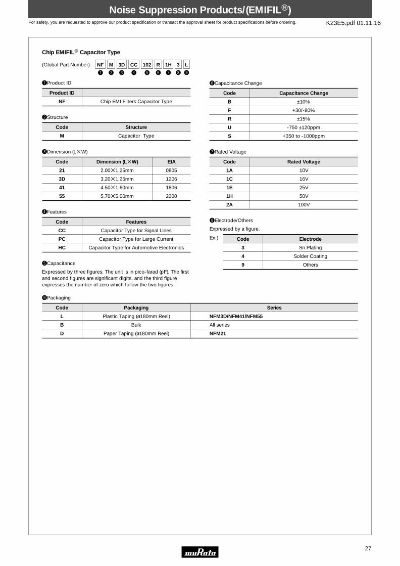
For safety, you are requested to approve our product specification or transact the approval sheet for product specifications before ordering. K23E5.pdf 01.11.16
t
102
q
NF
y
R
r
CC
e
3D
w
M
u
1H
i
3
o
L(Global Part Number)
Chip EMIFILr Capacitor Type
eDimension (LgW)
Code
2.00g1.25mm
3.20g1.25mm
4.50g1.60mm
5.70g5.00mm
Dimension (LgW)
0805
1206
1806
2200
EIA
21
3D
41
55
qProduct ID
NF Chip EMI Filters Capacitor Type
Product ID
wStructure
M Capacitor Type
Code Structure
rFeatures
Code
Capacitor Type for Signal Lines
Capacitor Type for Large Current
Capacitor Type for Automotive Electronics
Features
CC
PC
HC
tCapacitance
Expressed by three figures. The unit is in pico-farad (pF). The first and second figures are significant digits, and the third figure expresses the number of zero which follow the two figures.
yCapacitance Change
B
F
R
U
S
±10%
+30/-80%
±15%
-750 ±120ppm
+350 to -1000ppm
Code Capacitance Change
oPackaging
L
B
D
NFM3D/NFM41/NFM55
All series
NFM21
Plastic Taping (ø180mm Reel)
Bulk
Paper Taping (ø180mm Reel)
Code Packaging Series
3
4
9
Sn Plating
Solder Coating
Others
Code Electrode
uRated Voltage
1A
1C
1E
1H
2A
10V
16V
25V
50V
100V
Code Rated Voltage
iElectrode/Others
Expressed by a figure.
Ex.)
Noise Suppression Products/(EMIFILr)Noise Suppression Products/(EMIFILr)
27

For safety, you are requested to approve our product specification or transact the approval sheet for product specifications before ordering. K23E5.pdf 01.11.16
t
101
q
NF
y
S
r
CC
e
31
w
A
u
1E
i
4
o
B(Global Part Number)
Chip EMIFILr Capacitor Array Type
eDimension (LgW)
Code
3.20g1.60mm
Dimension (LgW)
31
qProduct ID
NF Chip EMI Filters Capacitor Type
Product ID
wStructure
A Array Type
Code Structure
rFeatures
Code
Capacitor Type for Signal Lines
Features
CC
tCapacitance
Expressed by three figures. The unit is in pico-farad (pF). The first and second figures are significant digits, and the third figure expresses the number of zero which follow the two figures.
yCapacitance Change
R
S
±15%
+350 to -1000ppm
Code Capacitance Change
oPackaging
B
D
Bulk
Paper Taping (ø180mm Reel)
Code Packaging
4 4 circuit
Code Number of Circuit
uRated Voltage
1C
1E
16V
25V
Code Rated Voltage
iNumbers of Circuit
Noise Suppression Products/(EMIFILr)Noise Suppression Products/(EMIFILr)
28

For safety, you are requested to approve our product specification or transact the approval sheet for product specifications before ordering. K23E5.pdf 01.11.16
(Global Part Number)
Chip EMIFILr LC Combined Type
eDimension (LgW)
Code
2.0g1.25mm
3.20g1.60mm
6.80g1.60mm
Dimension (LgW)
0805
1206
2606
EIA
21
31
61
qProduct ID
NF Chip EMI Filters LC Combined Type
Product ID
wStructure
L
W
E
Monolithic, LC Combined Type
Winding, LC Combined Type
Block, LC Combined Type
Code Structure
yCharacteristics (NFL/NFW Series)
X Cut off Frequency
Code Characteristics
oPackaging
K
L
B
D
NFW31/NFE
NFW31/NFE
NFL21/NFE
NFL21
Plastic Taping (ø330mm Reel)
Plastic Taping (ø180mm Reel)
Bulk
Paper Taping (ø180mm Reel)
Code Packaging Series
0
3
4
9
Ag / Pd Outer Electrode
Sn Plating
Solder Coating
Others
Code Electrode
uRated Voltage
1C
1E
1H
2A
16V
25V
50V
100V
Code Rated Voltage
tCut-off Frequency (NFL/NFW Series)
Expressed by three figures. The unit is in hertz (Hz). The first and second figures are significant digits, and the third figure expresses the number of zeros which follow the two figures.
rFeatures
Code
π Circuit for Signal Lines
T Circuit for Large Current
π Circuit for Automotive Electronics
T Circuit for Automotive Electronics
Features
SP
PT
HP
HTiElectrode
Expressed by a figure.
Ex.)
yCapacitance Change (NFE Series)
B
C
D
E
F
R
U
Z
±10%
±20%, ±22%
+20/-30%, +22/-33%
+20/-55%, +22/-56%
+30/-80%, +22/-82%
±15%
-750 ±120ppm/ ˚C
Other
Code Capacitance Change
tCapacitance (NFE Series)
Expressed by three figures. The unit is in pico-farad (pF). The first and second figures are significant digits, and the third figure expresses the number of zero which follow the two figures.
t
206
q
NF
y
X
r
SP
e
31 4
i o
L
w
W
u
1E
Noise Suppression Products/(EMIFILr)Noise Suppression Products/(EMIFILr)
29

For safety, you are requested to approve our product specification or transact the approval sheet for product specifications before ordering. K23E5.pdf 01.11.16
(Global Part Number)
Chip EMIFILr RC Combined Type
eDimension (LgW)
Code
2.00g1.25mm
Dimension (LgW)
21
qProduct ID
NF EMIFILr
Product ID
wStructure
R RC Combined Type
Code Structure
iPackaging
L
B
Plastic Taping (ø180mm Reel)
Bulk
Code Packaging
1
2
Ag Plating
Sn Plating
Code Electrode
tCapacitance
Expressed by three figures. The unit is in pico-farad (pF). The first and second figures are significant digits, and the third figure expresses the number of zero which follow the two figures. If there is a decimal point, it is expressed by capital letter "R". In this case, all figure are significant digits.
rFeatures
Code
RC Combined Type for Signal Lines
Features
GD
yResistance
Expressed by three figures. The unit is in ohm (Ω). The first and second figures are significant digits, and the third figure expresses the number of zero which follow the two figures. If there is a decimal point, it is expressed by capital letter "R". In this case, all figures are significant digits.
uElectrode/Others
t
470
y
470
q
NF
r
GD
e
21
w
R
u
2
i
L
0805
EIA
Noise Suppression Products/(EMIFILr)Noise Suppression Products/(EMIFILr)
30
t
100
y
101
q
NF
r
GD
e
31
w
A
u
4
i
D(Global Part Number)
Chip EMIFILr RC Combined Array Type
eDimension (LgW)
Code
3.20g1.60mm
Dimension (LgW)
31
qProduct ID
NF EMIFILr
Product ID
wStructure
A Array Type
Code Structure
iPackaging
B
D
Bulk
Paper Taping (ø180mm Reel)
Code Packaging
4 4 Circuit
Code Numbers of Circuit
tCapacitance
Expressed by three figures. The unit is in pico-farad (pF). The first and second figures are significant digits, and the third figure expresses the number of zero which follow the two figures. If there is a decimal point, it is expressed by capital letter "R". In this case, all figure are significant digits.
rFeatures
Code
RC Combined Type for Signal Lines
Features
GD
yResistance
Expressed by three figures. The unit is in ohm (Ω). The first and second figures are significant digits, and the third figure expresses the number of zero which follow the two figures. If there is a decimal point, it is expressed by capital letter "R". In this case, all figures are significant digits.
uNumbers of Circuit

For safety, you are requested to approve our product specification or transact the approval sheet for product specifications before ordering. K23E5.pdf 01.11.16
t
N
y
281
q
DL
u
S
r
K
e
31 2
o !0
L
w
M
i
J(Global Part Number)
Chip EMIFILr Common Mode Choke Coils
eDimension (LgW)
Code
2.00g1.20mm
3.20g1.60mm
2.50g2.00mm
5.00g3.60mm
5.00g5.00mm
Dimension (LgW)
0805
1206
–
–
–
EIA
21
31
2H
5A
5B
qProduct ID
DL Chip Common Mode Choke Coils
Product ID
wStructure
W
M
P
Monolithic Type
Winding Type
Film Type
Code Structure
tCategory
N Standard Type
Code Category
S
D
H
K
G
Magnetically Shielded One Circuit Type
Magnetically Shielded Two Circuit Type
Open Magnetic One Circuit Type
Magnetically Monolithic Type (bifilar winding)
Magnetically Monolithic Type (sectional winding)
Code Type
!0Packaging
K
L
B
DLW5AH/DLW5BS
All series
All series except DLM2H
Plastic Taping (ø330mm Reel)
Plastic Taping (ø180mm Reel)
Bulk
Code Packaging Series
2
3
4
Two Lines
Three Lines
Four Lines
Code Number of Signal Line
iFeatures
Expressed by an alphabet.
rType
yImpedance
Typical impedance at 100MHz is expressed by three figures. The unit is in ohm (Ω). The first and second figures are significant digits, and the third figure expresses the number of zero which follow the two figures.
uCircuit
S Standard Type
Code Circuit
oNumbers of Signal Line
Ex.)
Noise Suppression Products/(EMIFILr)Noise Suppression Products/(EMIFILr)
31

For safety, you are requested to approve our product specification or transact the approval sheet for product specifications before ordering. K23E5.pdf 01.11.16
t
R1
y
M
q
BL
r
2
e
RN
w
02
u
2
i
B(Global Part Number)
Lead Type EMIFILr Inductor Type
eBeads Core Material
Code
Standard Type
Beads Core Material
RN
qProduct ID
BL Ferrite Beads Inductors
Product ID
wSeries
01
02
03
Beads ø3.6
Beads ø3.4
Beads ø2.3 max.
Code Series
tLead Type
A1
A2
R1
R2
Axial Straight Type
Axial Crimp Type
Radial Straight Type
Radial Straight and wave formed Leads Type
Code Lead Type
iPackaging
A
B
J
BL01RN1A1E1A/BL02/BL03
All series
BL01RN1A1F1J
Ammo Pack
Bulk
Corrugated Reel (ø320mm)
Code Packaging Series
uLead Diameter
1
2
ø0.60mm
ø0.65mm
Code Lead Diameter
rNumbers of Beads Core
Code
1
2
Numbers of Beads Core
1
2
yLead Length, Space
A
B
C
D
E
F
G
H
J
K
L
M
N
P
Q
Bulk, Axial Type, 3.7mm
Bulk, Axial Type, 4.6mm
Bulk, Axial Type, 10.0mm
Bulk, Axial Type, 47.0mm
Taping Axial Type, 26.0mm
Taping, Axial Type, 52.0mm
Bulk, Radial Type, 3.5mm
Bulk, Radial Type, 4.0mm
Bulk, Radial Type, 5.0mm
Bulk, Radial Type, 6.0mm
Bulk, Radial Type, 8.0mm
Bulk, Radial Type, 10.0mm
Taping, Radial Type, 16.5mm
Taping, Radial Type, 18.5mm
Taping, Radial Type, 20.0mm
Code Lead Length, Space
Noise Suppression Products/(EMIFILr)Noise Suppression Products/(EMIFILr)
32

For safety, you are requested to approve our product specification or transact the approval sheet for product specifications before ordering. K23E5.pdf 01.11.16
t
B3
y
2E
q
DS
u
271
r
H
e
9 B
ow
S
i
Q55(Global Part Number)
Lead Type EMIFILr Capacitor Type
eStyle
Code
Diameter 8.0mm Type
Diameter 9.5mm Type
Style
6
9
qProduct ID
DS Three-terminals Capacitor
Product ID
wStructure
N
S
T
No Ferrite Beads Type
Built-in Ferrite Beads Type
with Ferrite Beads Type
Code Structure
tTemperature Characteristics
B3
D3
E3
F3
Z8
±10% (Temperature Range : -25˚C to +85˚C)
+20/-30% (Temperature Range : -25˚C to +85˚C)
+20/-55% (Temperature Range : -25˚C to +85˚C)
+30/-80% (Temperature Range : -25˚C to +85˚C)
+30/-85% (Temperature Range : -10˚C to +60˚C)
Code Temperature Characteristics
oPackaging
A
B
J
All series except DSS9
All series
DSS9
Ammo Pack
Bulk
Corrugated Reel (ø320mm)
Code Packaging Series
yRated Voltage
1C
1H
2A
2E
16V
50V
100V
250V
Code Rated Voltage
rCategory
Code
for General Use
for Heavy-duty
Category
N
H
uCapacitance
Expressed by three figures. The unit is in pico-farad (pF). The first and second figures are significant digits, and the third figure expresses the number of zero which follow the two figures.
iLead Type
Qpp
Tpp, Upp
Straight Type
Others
Code Lead Type
Noise Suppression Products/(EMIFILr)Noise Suppression Products/(EMIFILr)
33

For safety, you are requested to approve our product specification or transact the approval sheet for product specifications before ordering. K23E5.pdf 01.11.16
y
152
t
S
u
2R0
q
PL
r
A
e
10
w
A
i
R
o
2
!0
B(Global Part Number)
Lead Type Common Mode Choke Coils / AC Line Filters
eApplications
Code
for DC Line
for DC Line High-frequency Type
for AC Line
Applications
08
09
10
Code
Core Vertical Type
Core Horizontal Type
Case Type
Structure
A
H
C
qProduct ID
PL Common Mode Choke Coils
Product ID
wType
T
A
H
Y
DC Type
Standard Type
High-freqency Type
Hybrid Choke Coils Type
Code Type
!0Packaging
B
M
All series
PLT All series
Bulk
Magazine Package
Code Packaging Series
iWinding Mode
D
R
P
T
Sectional Winding Type
Standard Type
Aligned Winding Type
Troidal Type
Code Winding Mode
uRated Current
Expressed by three figures. The unit is in ampere (A). A decimal point is expressed capital letter "R". In this case, all figures are significant digits.
oLead Dimensions
2
1
0
3
3.5mm
5mm
4mm (PLT)
4mm (Except for PLT)
Code Lead Dimensions
rStructure
Code
Safety Recognized
General Use
Features
S
N
tFeatures
yInductance
Expressed by three figures. The unit is micro-henry (µH). The first and second figures are significant digits, and the third figure expresses the number of zero which follow the two figures. If there is a decimal point, it is expressed by capital letter "R". In this case, all figures are significant digits. If inductance is less than 0.1 µH, the inductance code is expressed by combination of two figures and capital letter "N", and the unit of inductance is nano-henry (nH). Capital letter "N" indicates the unit of "nH", and also expresses a decimal point. In this case, all figure are significant digits.
•Please contact us for FKOB type.
Noise Suppression Products/(EMIFILr)Noise Suppression Products/(EMIFILr)
34

For safety, you are requested to approve our product specification or transact the approval sheet for product specifications before ordering. K23E5.pdf 01.11.16
t
N
y
180
q
VC
u
D
r
R
e
18 1
o
L
!0w
M
i
S
t
N
y
222
q
VF
u
N
r
R
e
41 L
ow
M
i
1C
(Global Part Number)
Chip Varistors
qProduct ID
VC Chip Varistor
Product ID
wStructure
M Monolithic Type
Code Structure
iCharacteristics
S Standard Type
Code Characteristics
D
S
Ag/Pd
Sn
Code Electrode
uElectrode
Expressed by a figure.
yRated Voltage
eDimension (LgW)
Code
1.60g0.80mm
2.00g1.25mm
Dimension (LgW)
18
21
tCategory
Code
Standard Type
Category
N!0Packaging
L
B
Plastic Taping (ø180mm Reel)
Bulk
Code Packaging
rStyle
Code
Standard Type
Style
R
Expressed by three figures. The unit is in volts (V). The first and second figures are significant digits, and the third figure expresses the number of zero which follow the two figures. If there is a decimal point, it is expressed by capital letter "R". In this case, all figures are significant digits.
oNumber of Circuit
1 1 Circuit
Code Number of Circuit
Ex.)
(Global Part Number)
Chip EMIGUARDr (EMIFILr with Varistor Function)
eDimension (LgW)
Code
4.50g1.60mm
Dimension (LgW)
41
qProduct ID
VF Chip Solid EMIGUARDr
Product ID
wStructure
M Monolithic Type
Code Structure
uCapacitance Tolerance
N ±30%
Code Capacitance Tolerance
yCapacitance
Expressed by three figures. The unit is in pico-farad (pF). The first and second figures are significant digits, and the third figure expresses the number of zero which follow the two figures.
iRated Voltage
1C 16V
Code Rated Voltage
rOuter Electrode
Code
Standard Type
Outer Electrode
R
StandardN
tCategory
Code Category
oPackaging
L
B
Plastic Taping (ø180mm Reel)
Bulk
Code Packaging
0603
0805
EIA
Noise Suppression Products/(EMIFILr)Noise Suppression Products/(EMIFILr)
35
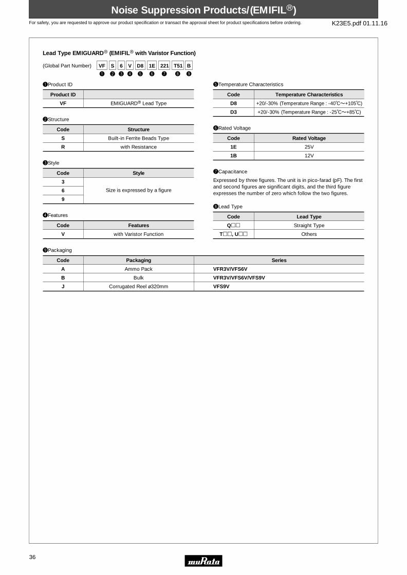
For safety, you are requested to approve our product specification or transact the approval sheet for product specifications before ordering. K23E5.pdf 01.11.16
t
D8
y
1E
q
VF
r
V
e
6
w
S
u
221
i
T51
o
B(Global Part Number)
Lead Type EMIGUARDr (EMIFILr with Varistor Function)
qProduct ID
VF EMIGUARDr Lead Type
Product ID
wStructure
S
R
Built-in Ferrite Beads Type
with Resistance
Code Structure
iLead Type
Qpp
Tpp, Upp
Straight Type
Others
Code Lead Type
uCapacitance
Expressed by three figures. The unit is in pico-farad (pF). The first and second figures are significant digits, and the third figure expresses the number of zero which follow the two figures.
yRated Voltage
1E
1B
25V
12V
Code Rated Voltage
rFeatures
Code
with Varistor Function
Features
V
tTemperature Characteristics
Code
+20/-30% (Temperature Range : -40˚Cb+105˚C)
+20/-30% (Temperature Range : -25˚Cb+85˚C)
Temperature Characteristics
D8
D3
oPackaging
A
B
J
VFR3V/VFS6V/VFS9V
VFS9V
VFR3V/VFS6VAmmo Pack
Bulk
Corrugated Reel ø320mm
Code Packaging Series
eStyle
3
6
9
Size is expressed by a figure
Code Style
Noise Suppression Products/(EMIFILr)Noise Suppression Products/(EMIFILr)
36

For safety, you are requested to approve our product specification or transact the approval sheet for product specifications before ordering. K23E5.pdf 01.11.16
wSeries
y
103
q
AR
q
CN
e
8
w
CL
e
8
w
TL
r
L
r
X
i
t
W
t
S
u
102
iu
102M
RC/C Module
SeriesCode
C
CL
TL
AR
CN
Standard (H : 7.6mm max.)
Low-profile Standard (H : 5.5mm max.)
Low-profile Standard (H : 5.5mm max.)
iOther Specifications
Lead PitchCode
None
W
S Shrink Pitch
AR Series
CNTL Series
Inch Pitch
Inch Pitch
qProduct ID
Product ID
RC Module
C Module
yResistance and Tolerance (RC Module)
rCircuit Type
tLead Pitch
Expressed by an alphabet.
eNumber of Lead Terminal
Expressed by one or two figures.
Expressed by three figures.
103 10000ΩT5%
Code Resistance and Tolerance
uCapacitance and Tolerance
RC Module : Expressed by three figures.C Module : Expressed by three figures and an alphabet.
102
102M
1000pF
1000pF, M : T20%
Code Capacitance and Tolerance
RC Module
C Module
RC Module
C Module
Please contact us for any other tolerance.
As for the tolerance of RC Modules.
(Global Part Number)
Ex.)
Ex.)
Noise Suppression Products/(EMIFILr)Noise Suppression Products/(EMIFILr)
37

For safety, you are requested to approve our product specification or transact the approval sheet for product specifications before ordering. K23E5.pdf 01.11.16
t
060
y
RT
q
FS
r
1
e
12
w
RB
u
B0
i
0
o
T
120
050
A50
B50
Z50
Z55
12.0mm
5.0mm
1.50mm
2.50mm
0.50mm
0.55mm
Expressed by three figures or combination of an alphabet and two figures. A to J (except I) indicates one to nine. Z indicates Zero.
(Global Part Number)
Ferrite Cores
qProduct ID
FS Ferrite
Product ID
wSeries
RH
RB
RC
MA
SA
Beads Core
Ring Core
for Flat Cable
Mutli-hole Core
Plate Core
Code Series
yMaterial
RN
RT
RX
Code Material
rOuter Dimension Suppliment Code
Code
Serial number is added in case their internal diameters are the same.
Outer Dimension Suppliment Code
0
iIndividual Specification Code
0 Standard Type
Code Individual Specification Code
eDimensions
Code
Approximately 12mm
Approximately 5mm
Dimensions
12
05
uProcess
00
B0
F0
Standard Type
Barrel Type
Separate Type
Code Process
tLength
Code Length
oPackaging
B
T
Bulk
Tray
Code Packaging
Ni-Zn µ=550
Ni-Zn µ=1600
Ni-Zn µ=750
Noise Suppression Products/(EMIFILr)Noise Suppression Products/(EMIFILr)
38

For safety, you are requested to approve our product specification or transact the approval sheet for product specifications before ordering. K23E5.pdf 01.11.16
ResonatorsResonators
39
qProduct ID
wFrequency/Capacitance
eStructure/Size
tDesign
uPackaging
CERALOCKr (MHz)
CS Ceramic Resontors
Gpp
T/Vpp
Xpp
A
T
MHz No capacitance built-in
MHz Built-in Capacitance
LA
LS
CC
CR/CE/CG
CV
CW
Lead Type
Round Lead Type
Cap Chip Type
Small-cap Chip Type
Monolithic Chip Type
Small Monolithic Chip Type
Thickness Shear mode
Thickness Expander mode
Thickness Expander mode (3rd overtone)
Three-digit alphanumerics express"Individual Specification".
Structure/Size
-B0
-A0
-A1
-R0
-R1
Packaging
Product ID
Code
Code
Code
yIndividual Specification
***
Code
Frequency/Capacitance
Design
Individual Specification
Code
(Global Part Number)
rNominal Center Frequency
Expressed by four-digit alphanumerics. The unit is in hertz (MHz). Decimal point is expressed by capital letter "M".
With standard products, "yIndividual Specification" is omitted, and "uPackage Specification Code" is carried up.
Bulk
Radial Taping H0=18mm
Radial Taping H0=16mm
Plastic Taping ø=180mm
Plastic Taping ø=330mm
y
***
e
CV
w
T
r
16M0
t
X53
u
-R0
q
CS
pp indicates initial frequency tolerance and load capacity.
Radial taping is applied to lead type and plastic taping to chip type.
y
***
e
FB
w
B
r
1M00
t
J58
u
-R1
q
CS
qProduct ID
wFrequency/Capacitance
eStructure/Size
rNominal Center Frequency
tDesign
uPackaging
CERALOCKr (kHz)
CS Ceramic Resontors Epp
Jpp
B kHz No capacitance built-in
LA
FB
Two-Terminal Lead Type
SMD Type
Area Expansion mode
Area Expansion mode (Closed Type)
Three-digit alphanumerics express "Individual Specification".Structure/Size
-B0
-R1
Packaging
Product ID
Code
Code
Code
yIndividual Specification
***
Code
Frequency/Capacitance
Design
Individual Specification
Code
(Global Part Number)
Expressed by four-digit alphanumerics. The unit is in hertz (Hz). Capital letter "K" following three figures expresses the unit of "kHz".
With standard products, "yIndividual Specification" is omitted, and "uPackage Specification Code" is carried up.
Bulk
Plastic Taping ø=330mm
pp indicates initial frequency tolerance and load capacitance.
o Part Numbering
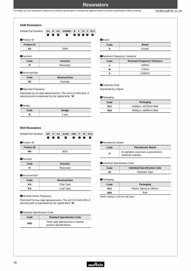
For safety, you are requested to approve our product specification or transact the approval sheet for product specifications before ordering. K23E5.pdf 01.11.16
ResonatorsResonators
40
y
X
e
UK
w
R
r
433M92
t
B
u
M
i
0
o
R11
q
SA
qProduct ID
wFunction
eStructure/Size
rResonant Frequency
tDesign
uResonant Frequency Tolerance
SAW Resonators
SA SAW
B
R Resonator
UK Package
1 port
Crystal
Structure/Size
L
M
P
Resonant Frequency Tolerance
Product ID
Code
Code
Code
yBoard
X
Code
Function
Design
Board
Code
(Global Part Number)
±50kHz
±75kHz
±100kHz
iCustomer Code
1000pcs. /ø178mm Reel
4000pcs. /ø330mm Reel
oPackaging
R11
R04
Code Packaging
Expressed by a figure.
y
P
e
KA
w
R
r
81M0
t
AB0
u
00
i
R11
q
MK
qProduct ID
wFunction
eStructure/Size
rNominal Center Frequency
tStandard Specification Code
uIndividual Specification Code
BGS Resonators
MK BGS
AB0
R Resonator
KA
GA
Chip Type
Lead Type
Three-digit alphanumerics expressproduct specifications.
An alphabet expresses a piezoelectric substrate material.
Structure/Size
00
Individual Specification Code
Product ID
Code
Code
Code
yPiezoelectric Board
P
Code
Function
Standard Specification Code
Piezoelectric Board
Code
(Global Part Number)
Standard Type
Plastic Taping ø=180mm
Bulk
iPackaging
R11
B05
Code Packaging
Plastic taping is only for chip type.
Expressed by six-digit alphanumerics. The unit is in hertz (Hz). A decimal point is expressed by the capital letter "M".
Expressed by four-digit alphanumerics. The unit is in hertz (Hz). A decimal point is expressed by the capital letter "M".

For safety, you are requested to approve our product specification or transact the approval sheet for product specifications before ordering. K23E5.pdf 01.11.16
Piezoelectric Sound ComponentsPiezoelectric Sound Components
41
y
-1R5
e
B
w
N
r
-31R2
t
DM
u i
A
o
10
q
7
qProduct ID(1)
wProduct(2)
eProduct
uWith Feedback Electrode
oIndividual Specification Code
Piezoelectric Diaphragms
7 A2
C
e
B
N
M
S
Brass
Nickel Alloy
Ni Plated Iron
SUS
B Piezoelectric Diaphragms
Two digits express shape of ceramics.
With Feedback Electrode
without Feedback Electrode
With lead
No lead (omitted)
Product
10
Individual Specification Code
Product ID(1) Ceramic Material
Product ID(2) Metal Plate Material
Code
Code
iProduct Specification
A
e
Code
With Feedback Electrode
Product Specification
Code
(Global Part Number)
rMetal Plate Diameter
-31R2
Metal Plate DiameterCode
A hyphen (-) plus four-digit alphanumerics express metal plate outer dimensions. A decimal point is expressed by the capital letter "R".
tForm of Piezoelectric Style
DM
Form of Piezoelectric StyleCode
yResonant Frequency Type
-1R5
Resonant Frequency (kHz)Code
A hyphen (-) and three-digit alphanumerics express resonant frequency. A decimal point is expressed by the capital letter "R".
These digits express a lead length, lead number, and presence/absence of a connector. If there is no decimal point, the decimal point code is omitted.
For an Ag electrode, this digit remains blank, the corresponding code is omitted.
If there is no decimal point, the decimal point is omitted.
If the product has no individual specification, the corresponding code is omitted.
qProduct ID
wProduct
eOuter Dimensions
yResonant Frequency Type
iNumbers of Ceramic
Piezoelectric Speakers (CERAMITONEr )
VS Piezoelectric Speakers
-03
-07
B Piezoelectric Diaphragms
35
50
ø35mm
ø50mm
1st Resonant Freqeuncy : 300Hz
1st Resonant Freqeuncy : 700Hz
Characteristics, Style, others
Outer Dimensions
B
Numbers of Ceramic
Product ID
Code
Code
Code
uIndividual Specification Code
01
Code
Product Resonant Frequency
Individual Specification Code
Code
(Global Part Number)
Two Elements (The code is omitted when element is one.)
rDrive
E External Drive
DriveCode
tOuter Electrode Style
W Lead Wire Type
Outer Electrode StyleCode
y
-07
e
35
w
B
r
E
t
W
u
01
i
B
q
VS
o Part Numbering

For safety, you are requested to approve our product specification or transact the approval sheet for product specifications before ordering. K23E5.pdf 01.11.16
Piezoelectric Sound ComponentsPiezoelectric Sound Components
42
y
Y
e
13
w
M
r
E
t
P
u
-40
i
00
o
P
!0
-A0
q
PK
qProduct ID
wProduct
yStructure
iIndividual Specification Code
Piezoelectric Sounders/Piezoelectric Buzzers/Piezoelectric Ringers(PIEZORINGERr)
PK Piezoelectric Sound Components
T
P
Y
C
M
B
Sounder, Ringer
Buzzer
Standing Type
Flat Type Auto-assemble
Flat Type/Available for Taping
Flat Type/Semi-auto-assemble
Product
00
Individual Specification Code
Product ID
Code
Code
uOscillating Frequency Type
Structure
Code
(Global Part Number)
Pin Type
Lead Wire Type
eOuter Dimensions
rDrive
E
S
DriveCode
tOuter Electrode Style
P
W
Outer Electrode StyleCode
Post Plated Terminal
Omitted
oSpecial Quality Guarantee
P
Y
Special Quality GuaranteeCode
Bulk
Radial Taping
Magazine
!0Packaging
-B0
-A0
-M0
PackagingCode
Two digits express specific specification in characteristics.
Expressed by two figures in mm.
13
Ex.)
ø12.6mm
External-Drive
Self-Drive
Code Outer Dimensions
Radial taping or magazine are not available for all types.Please contact us.
-40
Oscillating Frequency TypeCode
A hyphen (-) plus two-digit figures express Oscillating Frequency type.
If there is no decimal point, the decimal point is omitted.
qProduct ID
SMD Piezoelectric Sounder
PK Piezoelectric Sound Components
Product ID
(Global Part Number)
y
01
e
1212
w
LCS
r
E
t
40
u
-R1
q
PK
wProduct
LCS SMD Sounder
Code Product
eDimensions
1212 p12mm
Code Outer Dimensions
rDrive
E External Drive
Code
tOscillating Frequency Type
40A hyphen (-) plus two-digit figures expressOscillating Frequency type.
Code
yIndividual Specification Code
01Two digit express specific specification in characteristics.
Code Individual Specification Code
uPackaging
-B0
-R1
Bulk
Plastic taping
Code Packaging

For safety, you are requested to approve our product specification or transact the approval sheet for product specifications before ordering. K23E5.pdf 01.11.16
Piezoelectric Sound ComponentsPiezoelectric Sound Components
43
qProduct ID
SMD Piezoelectric Receiver
PK Piezoelectric Sound Components
Product ID
(Global Part Number)
y
00
e
1212
w
LCD
r
E
t
10
u
-R1
q
PK
wProduct
LCD SMD Receiver
Code Product
eDimensions
1212 p12mm
Code Outer Dimensions
rDrive
R Receiver
Code
tOscillating Frequency Type
10A hyphen (-) plus two-digit figures expressOscillating Frequency type.
Code
yIndividual Specification Code
00Two digit express specific specification in characteristics.
Code Individual Specification Code
uPackaging
-B0
-R1
Bulk
Plastic taping
Code Packaging

For safety, you are requested to approve our product specification or transact the approval sheet for product specifications before ordering. K23E5.pdf 01.11.16
Filters for Communication EquipmentFilters for Communication Equipment
44
(Global Part Number)
qProduct ID
wSeries
Antenna/Duplexer Dielectric Filters (GIGAFILr)
for RF/Local Dielectric Filters (GIGAFILr)
DF Microwave Filters (GIGAFILr)
Tray
Reel
Product ID
tPackaging
T**
R**
Code PackagingTwo capital letters and an alphabet express the series name.
rIndividual Specification Code
Expressed by five alphabets plus a hyphen.
eNominal Center Frequency
Expressed by four-digit alphanumerics. If the unit is "MHz", it is expressed by three figures plus "M". If the unit is "GHz", a decimal point is expressed by capital letter "G".
Packaging varies on each product type. Please contact us for details.
LBNBB-
ew
YK6
r t
1G95 TT1
q
DF
y
1
e
32
w
B
r
836M
t
SA
u
-747
q
LF(Global Part Number)
qProduct ID
Chip Multilayer LC Filters for RF/Local and IF
LF Chip Multilayer LC Filters
Two capital letters express the series name.
Product ID
tSeries
SA
Code Series
rNominal Center Frequency
Expressed by four-digit alphanumerics. If the unit is "MHz", it is expressed by three figures plus "M". If the unit is "GHz", a decimal point is expressed by capital letter "G".
A figure expresses identificationof the series design type.
yDesign
1
Code Design
Specification, Characteristics, others
uIndividual Specification Code
-747
Code Individual Specification Code
Band-pass Filters
Low-pass Filters
Multi-function Filters
Trap
wFunction
B
L
D
E
Code Function
1.60g0.80mm
2.00g1.25mm
3.20g1.60mm
3.20g2.50mm
4.50g3.20mm
5.70g5.00mm
eDimensions (LgW)
18
21
31
32
43
55
Code Dimensions (LgW)
o Part Numbering

For safety, you are requested to approve our product specification or transact the approval sheet for product specifications before ordering. K23E5.pdf 01.11.16
Filters for Communication EquipmentFilters for Communication Equipment
45
y
T
e
CC
w
F
r
942M
t
VM0
u
00
i
R05
q
SA(Global Part Number)
qProduct ID
SAW Filters for RF/Local and IF
SA SAW
Product ID
tCharacter Design
VM0
Code Character Design
rNominal Center Frequency
yBoard
T
Code Board
e
uIndividual Specification
00
Code Individual Specification
10000 pcs./ø330mm Reel
5000 pcs./ø330mm Reel
1000 pcs./ø180mm Reel
iPackaging
R00
R05
R11
Code Packaging
Single Filter
Dual Filter
wFunction
F
W
Code Function
Package Type
eStructure/Size
CC
Code Structure/Size
A serial number expresses the design version.
Expressed by four-digit alphanumerics. The unit is hertz (Hz). If the unit is "MHz", it is expressed by three figures plus "M". If the unit is "GHz", a decimal point is expressed by capital letter "G".
Expresses the substrate being used.
y
001
e
CA
w
X
r
450K
t
CFA
u
-R0
q
CF
CAP 455K D4A -R0SF
00CSE 10M8 PF00 -R0SF
(Global Part Number)
qProduct ID
wOscillating/Element
Ceramic Filters (CERAFILr) for IF
CF
SF
U
W
X
P
E
S
J
CERAFILr forCommunicationEquipment
Three alphabets express pass band width, center frequency tolerance and design type.
Product ID
tProduct Specification
CFA
Code Product Specification
rNominal Center Frequency
Expressed by four-digit alphanumerics. The unit is hertz (Hz). If the unit is "kHz", it is expressed by three figures plus "K". If the unit is "MHz", a decimal point is expressed by the capital letter "M".
p is "A" or subsequent code, which indicates the size. It varies depending on vibration mode and number of elements.
Expressed by three-digit alphanumerics.
yIndividual Specification
001
Code Individual Specification Code
Bulk
Plastic Taping ø=180mm
Plastic Taping ø=330mm
Magazine
uPackaging
-B0
-R0
-R1
-M0
Code Packaging
Oscillating/Element
Chip Type
Lead Type
eStructure/Size
Cp
Lp
Code Structure/Size
4 Elements Area Expansion mode
6 Elements Area Expansion mode
4 Elements Length mode
4 Elements Area Expansion mode
2 Elements Thickness Expansion mode
2 Elements Thickness Shear mode
4 Elements Thickness Shear mode
Magazine casette is applied to lead type and plastic taping to chip type.

For safety, you are requested to approve our product specification or transact the approval sheet for product specifications before ordering. K23E5.pdf 01.11.16
Filters for Communication EquipmentFilters for Communication Equipment
46
y
P
e
KB
w
F
r
51M7
t
JA0
u
00
i
R11
q
MK(Global Part Number)
qProduct ID
BGS Filter for IF
MK BGS Expressed by three figures.
Product ID
tProduct Specification
JA0
Code Product Specification
rNominal Center Frequency
Expressed by four-digit alphanumerics. The unit is hertz (Hz). If the unit is "MHz", it is expressed by three figures plus "M".
Expressed by an alphabet.
yPiezoelectric Board Material
P
Code Piezoelectric Board Material
Standard
uIndividual Specification Code
00
Code Individual Specification Code
Plastic Taping ø=180mm
iPackaging
R11
Code Packaging
Filter
wFunction
F
Code Function
Chip Type
eStructure/Size
KB
Code Structure/Size
y
A
e
LB
w
B
r
450K
t
C
u
X
i
16
o
-B0
q
CD(Global Part Number)
qProduct ID
Ceramic Discriminators for IF
CD Ceramic Discriminators
Quadrature Detection
Product ID
tDetection
C
Code Detection
Magazine casette is applied to lead type and plastic taping to chip type. With non-standard products, one alphabet indicating "Individual Specification" is added between "iApplicable IC" and "oPackage Specification code".
p is "A" or subsequent code, which indicates the size. It varies depending on vibration mode and number of elements.
Standard
Application with coil
yApplication
A
L
Code Application
Low-capacitance
High-capacitance
uElement Type
X
Y
Code Element Type
Applicable IC Control code
iIC
16
Code IC
Bulk
Plastic Taping ø=180mm
Plastic Taping ø=330mm
Magazine
oPackaging
-B0
-R0
-R1
-M0
Code Packaging
Area Expansion mode
wOscillating
B
Code Oscillating
Chip Type
Lead Type
eStructure/Size
Cp
Lp
Code Structure/Size
rNominal Center Frequency
Expressed by four-digit alphanumerics. The unit is in hertz (Hz). Capital letter "K" following three figures expresses the unit of "kHz".

For safety, you are requested to approve our product specification or transact the approval sheet for product specifications before ordering. K23E5.pdf 01.11.16
Microwave ComponentsMicrowave Components
47
y
B
u
-027
e
21
w
C
r
897M
t
20
q
LD(Global Part Number)
qProduct ID
wFunction
Chip Multilayer Hybrid Couplers/Chip Multilayer Hybrid Dividers
LD
Product ID
Spcification, Characteristics, others
uIndividual Specification Code
-027
Code Individual Specification Code
Couplers
Dividers
Chip Multilayer Devices
C
D
Code Function
1.60g0.80mm
2.00g1.25mm
3.20g1.60mm
3.20g2.50mm
4.50g3.20mm
5.70g5.00mm
18
21
31
32
43
55
Code Dimension (LgW)
0603
0805
1206
1210
1812
2220
EIA
eDimension (LgW)
tCoupling
yDesign
Couplers Single Type
with Integrated LPF
with Integrated LPF
Dividers Standard Type
B
H
L
A
Code Design
03
14
20
Ex.)
3dB
14dB
20dB
Code Coupling
Expressed by two figures.
rNominal Center Frequency
Expressed by four figures. If the unit is "MHz", it is expressed by three figures plus "M". If the unit is "GHz", a decimal point is expressed by capital letter "G".
(Global Part Number)
qProduct ID
wSeries
Isolators
CE Isolators
Bulk
250 pcs. /Reel (CE053, CE073)
1000 pcs. /Reel (CE053, CE073)
500 pcs. /Reel (CE040, CE041)
2000 pcs. /Reel (CE040, CE041)
Product ID
tPackaging
TT1
RCA
RD1
RAB
RB2
Code Packaging
rIndividual Specification Code
Expressed by three alphabets and three digits serial number.
eNominal Center Frequency
Expressed by four-digits alphanumerics. If the unit is "MHz", it is expressed by three figures plus "M". If the unit is "GHz", a decimal point is expressed by capital letter "G".
5g5g2mm
7g7g2mm
4g4g2mm
4g4g1.7mm
053
073
040
041
Code Series
e
1G95
w
040
r
DCB000
q
CE
t
RAB
o Part Numbering

For safety, you are requested to approve our product specification or transact the approval sheet for product specifications before ordering. K23E5.pdf 01.11.16
Microwave ComponentsMicrowave Components
48
yPackage Product ID
uPackage Detail(1)
iPackage Detail(2)
R
T
Reel
Tray
Code Package Product ID
F
D
T
Tape Width 24mm ø330mm
Tape Width 16mm ø330mm
Tray Specification
Code Package Detail(1)
1
1
Package Quantity per Reel(Ex: 1=1000pcs/reel)
Tray Specification
Code Package Detail(2)
(Global Part Number)
qProduct ID
wFunction
Chip Multilayer Hybrid Baluns
LD
Product ID
Spcification, Characteristics, others
uIndividual Specification Code
-001
Code Individual Specification Code
Baluns
Chip Multilayer Devices
B
Code Function
21
31
Code
eDimension (LgW)
tBalanceport Impedance
yDesign
StandardC
Code Design
50Ω
100Ω
200Ω
05
10
20
Code Balanceport Impedance
rNominal Center Frequency
Expressed by four figures. If the unit is "MHz", it is expressed by three figures plus "M". If the unit is "GHz", a decimal point is expressed by capital letter "G".
y
C
u
-001
e
21
w
B
r
836M
t
20
q
LD
y
R
u
F
e
G1
w
C
i
1SAA003
tq
AN 1G48
r
(Global Part Number)
qProduct ID
wFunction
Chip Dielectric Antennas
AN
Product ID
Chip Dielectric Antennas
Dielectric Antennas
C
Code Function
eSeries
tIndividual Specification Code
Expressed by an alphabet and a figure.
Expressed by three alphabets and a three-digit serial number.
rNominal Center Frequency
Expressed by four figures. If the unit is "MHz", it is expressed by three figures plus "M". If the unit is "GHz", a decimal point is expressed by capital letter "G".
2.00g1.25mm
3.20g1.60mm
Dimension (LgW)
0805
1206
EIA

For safety, you are requested to approve our product specification or transact the approval sheet for product specifications before ordering. K23E5.pdf 01.11.16
Microwave ComponentsMicrowave Components
49
(Global Part Number)
qProduct ID
wProduct
Dielectric Resonators (RESOMICSr) TE Mode
DR
Product ID
uResonant Frequency Temperature Characteristics(Tf) Tolerance
TE Mode (Disc Type)
TE Mode (Tube Type)
Dielectric Resonators(RESOMICSr)
D
T
Code Product
Expressed by three figures. The unit is 1/10mm.055
Code Outer Diameter
Expressed by four figures. The unit is 1/100mm.0244
Code Thickness
eOuter Diameter
tMaterials
yResonant Frequency Temperature Characteristics(Tf)
±2 ppm/˚C
±1 ppm/˚C
±0.5ppm/˚C
Z
A
B
CodeResonant Frequency
Temperature Characteristics(Tf) Tolerance
U Series
M Series
V Series
R Series
B Series
E Series
F Series
U
M
V
R
B
E
F
Code Materials
rThickness
Standard Type00
Code Individual Specification Code (Serial)
iIndividual Specification Code (Serial)
Bulk
Taping
T
R
Code Packaging
oPackaging
C0
20
Ex.)
Y2.0 ppm/˚C
2.0 ppm/˚C
CodeResonant Frequency
Temperature Characteristics(Tf) Tolerance
Expressed by two figures or combination of an alphabet and a figure.
y
20
u
B
i
00
o
R
e
055
w
D
r
0244
t
M
q
DR

For safety, you are requested to approve our product specification or transact the approval sheet for product specifications before ordering. K23E5.pdf 01.11.16
Microwave ComponentsMicrowave Components
50
(Global Part Number)
qProduct ID
wProduct
Dielectric Resonators (RESOMICSr) TEM Mode
DR
Product ID
uElectrode
TEM Mode
Dielectric Resonators(RESOMICSr)
R
Code Product
2.0g2.0mm
3.0g3.0mm
4.0g4.0mm
6.0g6.0mm
020
030
040
060
Code Outer Diameter
eOuter Diameter
tMaterials
yWave Length
U Series
K Series
P Series
U
K
P
Code Materials
rNominal Center Frequency
Expressed by five figures. If the unit is "MHz", it is expressed by three figures plus "M". If the unit is "GHz", a decimal point is expressed by capital letter "G".
900M0
1G200
Ex.)
900MHz
1200MHz
Code Nominal Center Frequency
Standard00
Code Individual Specification Code (Serial)
iIndividual Specification Code (Serial)
Bulk
Taping
T
R
Code Packaging
λ /4
λ /2
T
P
Code Wave Length
Copper
Silver
C
S
Code Electrode
oPackaging
y
T
u
C
i
00
o
R
e
020
w
R
r
1G590
t
K
q
DR

For safety, you are requested to approve our product specification or transact the approval sheet for product specifications before ordering. K23E5.pdf 01.11.16
Microwave ComponentsMicrowave Components
51
(Global Part Number)
qProduct ID
wSeries
High-Frequency Microchip Capacitors
CL High-Frequency Microchip Capacitors
-25 to 85˚C
-25 to 85˚C
-25 to 85˚C
-25 to 85˚C
-25 to 85˚C
-25 to 85˚C
0±30ppm/˚C
-750±60ppm/˚C
-2200±500ppm/˚C
±10%
+30,-80%
+30,-90%
Product ID
rTemperature Characteristics
5C
6U
7K
B5
F9
W1
Code Temperature Range Capacitance Change
tCapacitance
Expressed by three figures. The unit is pico-farad (pF). The first and second figures are significant digits, and the third figure expresses the number of zeros which follow the two numbers.If there is a decimal point, it is expressed by the capital letter "R". In this case, all figures are significant digits.
±0.1pF
±10%
±20%
+80%, -20%
yCapacitance Tolerance
B
K
M
Z
Code Capacitance Tolerance
1
3
4
5
uNumbers of Electrode
1
3
4
5
Code Number of Electrode
Standard
iIndividual Specification Code
000
Code Individual Specification Code
Tray
oPackaging
TC1
Code Packaging
with Border on Both SidesB
Code Series
eSize
0.25g0.25mm
0.30g0.25mm
0.35g0.25mm
0.38g0.38mm
0.55g0.38mm
0.71g0.38mm
0.50g0.50mm
0.70g0.50mm
0.90g0.50mm
0.64g0.64mm
1.00g0.64mm
0.76g0.76mm
1.09g0.76mm
0.90g0.90mm
1.49g0.90mm
1.27g1.27mm
1.73g1.27mm
2.19g1.27mm
1.78g1.78mm
2.95g1.78mm
2.29g2.29mm
3.71g2.29mm
0A
0B
0C
0D
0E
0H
05
0G
0K
0F
1A
0J
1B
09
1E
1C
1G
2C
1H
2L
2E
3G
Code Size
y
K
e
05
w
B
r
B5
t
390
u
1
i
000
o
TC1
q
CL
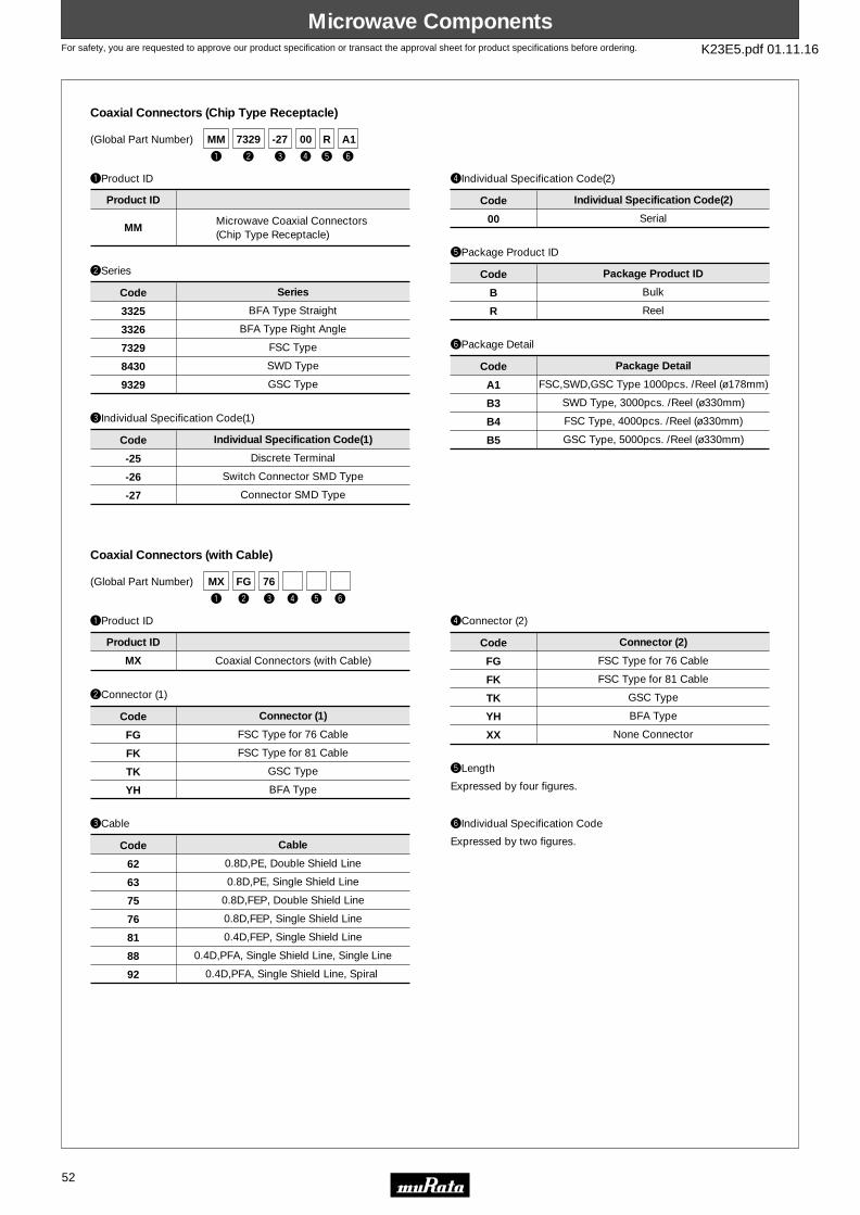
For safety, you are requested to approve our product specification or transact the approval sheet for product specifications before ordering. K23E5.pdf 01.11.16
Microwave ComponentsMicrowave Components
52
(Global Part Number)
qProduct ID
wSeries
Coaxial Connectors (Chip Type Receptacle)
MMMicrowave Coaxial Connectors (Chip Type Receptacle)
Product ID
FSC,SWD,GSC Type 1000pcs. /Reel (ø178mm)
SWD Type, 3000pcs. /Reel (ø330mm)
FSC Type, 4000pcs. /Reel (ø330mm)
GSC Type, 5000pcs. /Reel (ø330mm)
yPackage Detail
A1
B3
B4
B5
Code Package Detail
Bulk
Reel
tPackage Product ID
B
R
Code Package Product ID
BFA Type Straight
BFA Type Right Angle
FSC Type
SWD Type
GSC Type
3325
3326
7329
8430
9329
Code Series
eIndividual Specification Code(1)
Discrete Terminal
Switch Connector SMD Type
Connector SMD Type
-25
-26
-27
Code Individual Specification Code(1)
rIndividual Specification Code(2)
Serial00
Code Individual Specification Code(2)
(Global Part Number)
qProduct ID
wConnector (1)
Coaxial Connectors (with Cable)
MX
Product ID
FSC Type for 76 Cable
FSC Type for 81 Cable
GSC Type
BFA Type
Coaxial Connectors (with Cable)
FG
FK
TK
YH
Code Connector (1)
eCable
0.8D,PE, Double Shield Line
0.8D,PE, Single Shield Line
0.8D,FEP, Double Shield Line
0.8D,FEP, Single Shield Line
0.4D,FEP, Single Shield Line
0.4D,PFA, Single Shield Line, Single Line
0.4D,PFA, Single Shield Line, Spiral
62
63
75
76
81
88
92
Code Cable
rConnector (2)
FSC Type for 76 Cable
FSC Type for 81 Cable
GSC Type
BFA Type
None Connector
FG
FK
TK
YH
XX
Code Connector (2)
tLength
Expressed by four figures.
yIndividual Specification Code
Expressed by two figures.
y
A1
e
-27
w
7329
r
00
t
R
q
MM
e
76
w
FG
r t yq
MX

For safety, you are requested to approve our product specification or transact the approval sheet for product specifications before ordering. K23E5.pdf 01.11.16
Microwave ModulesMicrowave Modules
53
(Global Part Number)
qProduct ID
wFunction
RF Diode Switches
LM Multilayer Modules
Product ID
tIndividual Specification Code
rDesign
Two capital letters express identification of design type for each function.
Specificaions, Characteristics, others
RF Diode Switches
Switchplexerr
SW
SP
Code Function
eDimension (LgW)
4.50g3.20mm
6.30g5.00mm
43
65
Code Dimension (LgW)
e
43
w
SW
r
KA
t
-207
q
LM
y
R
e
11
w
W
r
2B
t
897M
u
5
q
MQ(Global Part Number)
qProduct ID
wSeries
VCO
MQ VCO
Product ID
tNominal Center Frequency
Expressed by four figures. If the unit is "MHz", it is expressed by three figures plus "M". If the unit is "GHz", a decimal point is expressed by capital letter "G".
rSerial Number
Expressed by an alphabet and a figure.
Dual VCO
7.6g5.8mm min.
5.5g4.8mm min.
5.0g4.0mm min.
W
E
K
L
Code Series
eDimension/Application
Pin Layout, Type11
Code Dimension/Application
yPackage Product ID
TapingR
Code Package Product ID
uPackage Detail
Quantity, direction of reel5
Code Package Detail
y
R
e
D31P15A
w
Q
r
01
t
A
u
5
q
HF(Global Part Number)
qProduct ID
wSeries
PLL Modules
HF Module Products
Product ID
tOthers
rSerial Number
PLL ModulesQ
Code Series
eDimension/Application
Size, SystemD31P15A
Code Dimension/Application
yPackage Product ID
TapingR
Code Package Product ID
Specification Change CodeA
Code Others
uPackage Detail
Quantity, direction of reel5
Code Package Detail
rSerial Number
Expressed by two figures.
o Part Numbering

For safety, you are requested to approve our product specification or transact the approval sheet for product specifications before ordering. K23E5.pdf 01.11.16
Filters for Audio Visual EquipmentFilters for Audio Visual Equipment
54
(Global Part Number)
qProduct ID
wOscillation/Numbers of Element
CERAFILr for AM
PF
SF
CF
Ceramic Filters
Ceramic Filters
Ceramic Filters
Standard Type
Product ID
tProduct Specification
P2A
Code Product Specification
ppA indicates standard type.
p is "A" or subsequent code, which indicates the size. It varies depending on vibration mode and number of elements.
eStructure/Size
Bulk
Plastic Taping (ø180mm)
Plastic Taping (ø330mm)
Radial Taping H0=18mm
Magazine Cassette
yPackaging
-B0
-R0
-R1
-A0
-M0
Code Packaging
Radial taping is applied to lead type and plastic taping to chip type.With non-standard products, three-digit alphanumerics indicating "Individual Specification" is added between "tProduct Specification" and "yPackaging".
1 Element Length mode
2 Elements Length mode
1 Element Area Expansion mode
2 Elements Area Expansion mode
4 Elements Area Expansion mode
S
W
U
Z
P
Code Oscillation/Numbers of Element
Lead Type
Chip Type
Lp
Cp
Code Structure/Size
y
-B0
e
LA
w
W
r
450K
t
P2A
q
PF
y
-B0
e
LA
w
U
r
450K
t
C
q
BF(Global Part Number)
qProduct ID
wOscillation/Numbers of Element
CERAFILr for Search-stop Signal Detection
BF Resonator Bandwidth
Product ID
tProduct Specification
Cp
Code Product Specification
rNominal Center Frequency
With standard type, p is omitted.
eStructure/Size
450kHz450K
Code Nominal Center Frequency
Bulk
yPackaging
-B0
Code Packaging
Radial taping is applied to lead type and plastic taping to chip type.With non-standard products, "Individual Specification (serial number)" and "Lead Shape (Lead Bend : B)" are added between "tProduct Specification" and "yPackage Specification Code" upon specification.
1 Element Area Expansion modeU
Code Oscillation/Numbers of Element
Lead Type StandardLA
Code Structure/Size
rNominal Center Frequency
Expressed by four-digit alphanumerics. The unit is in hertz (Hz). Capital letter "K"following three figures expresses the unit of "kHz".
o Part Numbering

For safety, you are requested to approve our product specification or transact the approval sheet for product specifications before ordering. K23E5.pdf 01.11.16
Filters for Audio Visual EquipmentFilters for Audio Visual Equipment
55
e
LA
w
E
q
SF
r
10M7
t
FAA0
y
-R0(Global Part Number)
qProduct ID
wOscillation/Numbers of Element
CERAFILr for FM
SF Ceramic Filters Four-digit alphanumerics expresspass-bandwidth, center frequency tolerance,rank, series, others.
Product ID
tProduct Specification
FAA0
Code Product Specification
p is expressed "A" or subsequent code, which indicates the size.
eStructure/Size
Bulk
Plastic Taping ø180mm
Plastic Taping ø330mm
1500pcs. /Radial Taping H0=18mm
1000pcs. /Radial Taping H0=18mm
yPackaging
-B0
-R0
-R1
-A0
-A1
Code Packaging
Radial taping is applied to lead type and plastic taping to chip type.With non-standard products, two-digit alphanumerics indicating "Individual Specification" is added between "tProduct Specification" and "yPackaging".
2 Elements Thickness Expander mode
3 Elements Thickness Expander mode
2 Elements Thickness Expander mode(2nd Harmonic)
2 Elements Thickness Expander mode(3rd Over Tone)
E
T
K
V
Code Oscillation/Numbers of Element
Lead Type
Chip Type
Lp
Cp
Code Structure/Size
rNominal Center Frequency
Expressed by four-digit alphanumerics. The unit is in hertz (MHz).Decimal point is expressed by capital letter "M".
e
LA
w
A
r
10M7
t
GA
u
-R0
y
001
q
CD(Global Part Number)
qProduct ID
wOscillation
Discriminators for FM
CD Discriminators
Product ID
tProduct Specification
GA
Code Product Specification
Radial taping is applied to lead type and plastic taping to chip type.With non-standard products, an alphanumerics indicating "Individual Specification" is added between "yIC" and "uPackaging".
eStructure/Size
Bulk
Radial Taping H0=18mm
Plastic Taping (ø180mm)
Plastic Taping (ø330mm)
yIC
001
Code IC
Applicable IC Control Code
uPackaging
-B0
-A0
-R0
-R1
Code Packaging
Thickness Expander modeA
Code Oscillation
Lead Type
Chip Type
Lp
Cp
Code Structure/Size
p is expressed "A" or subsequent code, which indicates the size.
Two-digit alphanumerics expresstype, center frequency, rank, others
rNominal Center Frequency
Expressed by four-digit alphanumerics . The unit is in hertz (MHz).Decimal point is expressed by capital letter "M".

For safety, you are requested to approve our product specification or transact the approval sheet for product specifications before ordering. K23E5.pdf 01.11.16
Filters for Audio Visual EquipmentFilters for Audio Visual Equipment
56
u
-B0
e
RA
w
S
r
4M50
y
00
t
CF
q
SF(Global Part Number)
qProduct ID
wOscillation/Numbers of Element
CERAFILr for TV/VCR
SF Ceramic Filters
Product ID
tProduct Specification Code (1)
AF
BF
CF
DF
EF
Code Product Specification Code (1)
Radial taping is applied to lead type and plastic taping to chip type.With non-standard products, two-digit alphanumerics indicating "Individual Specification" is added between "tProduct Specification Code (1)" and "yProduct Specification Code (2)".
eStructure/Size
Bulk
Radial Taping H0=18mm
Plastic Taping ø=330mm
Standard Bandwidth Type
Tight Bandwidth Type
Standard Bandwidth Type
Broad Bandwidth Type
Ultra-broad Bandwidth Type
yProduct Specification Code (2)
00
Code Product Specification Code (2)
Standard Type
uPackaging
-B0
-A0
-R1
Code Packaging
2 Elements Thickness Shear mode
3 Elements Thickness Expander mode
S
T
Code Oscillation/Numbers of Element
Lead Type
Chip Type
Rp
Kp
Code Structure/Size
p is expressed "A" or subsequent code, which indicates the size.
The code AF is only applied to SFT series.
rNominal Center Frequency
Expressed by four-digit alphanumerics. The unit is in hertz (MHz).Decimal point is expressed by capital letter "M".
e
RH
w
S
r
4M50
t
E
y
K
i
-A0
u
048
q
CD(Global Part Number)
qProduct ID
wOscillation
Discriminators for TV/VCR
CD Discriminators
Product ID
tProduct Specification Code (1)
C
E
Code Product Specification Code (1)
With non-standard products, an alphabet Indicating "Individual Specification" is added between "uIC" and "iPackaging".
eStructure/Size
Bulk
Radial Taping H0=18mm
Three-terminals
Two-terminals
yProduct Specification Code (2)
K
Code Product Specification Code (2)
Specification
uIC
048
Code IC
Applicable IC control code
iPackaging
-B0
-A0
Code Packaging
Thickness Shear modeS
Code Oscillation
Standard Type
Low-profile
RH
RL
Code Structure/Size
rNominal Center Frequency
Expressed by four-digit alphanumerics. The unit is in hertz (MHz).Decimal point is expressed by capital letter "M".

For safety, you are requested to approve our product specification or transact the approval sheet for product specifications before ordering. K23E5.pdf 01.11.16
Filters for Audio Visual EquipmentFilters for Audio Visual Equipment
57
y
00
u
-B0
e
RA
w
S
r
4M50
t
B
q
TP(Global Part Number)
qProduct ID
wFunction
Ceramic Traps
TP Ceramic Traps
Product ID
tProduct Specification Code (1)
B
C
Code Product Specification (1)
Radial taping is applied to lead type and plastic taping to chip type.With non-standard products, three-digit alphanumerics indicating "Individual Specification" is added between "yProduct Specification Code (2)" and "uPackaging".
eStructure/Size
Bulk
Radial Taping H0=18mm
Plastic Taping ø=330mm
Broad-bandwidth Type
Low-capacitance Type
yProduct Specification Code (2)
00
Code Product Specification Code (2)
Standard Type
uPackaging
-B0
-A0
-R1
Code Packaging
Single Traps
Triple Traps
Double Traps
S
T
W
Code Function
Lead Type
Chip Type
Rp
Kp
Code Structure/Size
p is expressed "A" or subsequent code, which indicates the size.
rNominal Center Frequency
Expressed by four-digit alphanumerics. The unit is in hertz (MHz).Decimal point is expressed by capital letter "M".
e
GA
w
T
r
47M2
t
CAH
u
00
i
B05
y
P
q
MK(Global Part Number)
qProduct ID
wFunction
BGS Traps
MK BGS
Product ID
tProduct Specification (1)
AA
CA
Code Product Specification (1)
eStructure/Size
Bulk
Radial Taping H0=18mm
Standard Bandwidth
Narrow-bandwidth
tProduct Specification (2)
H
L
Code Product Specification (2)
High-freqency side Traps
Low-freqency side Traps
yPiezoelectric Board Material
P
Code Piezoelectric Board Material
Expressed by an alphabet.
uIndividual Specification Code
00
Code Individual Specification Code
Standard
iPackaging
B05
A03
Code Packaging
TrapsT
Code Function
Lead TypeGA
Code Structure/Size
rNominal Center Frequency
Expressed by four-digit alphanumerics. The unit is in hertz (MHz).Decimal point is expressed by capital letter "M".

For safety, you are requested to approve our product specification or transact the approval sheet for product specifications before ordering. K23E5.pdf 01.11.16
Filters for Audio Visual EquipmentFilters for Audio Visual Equipment
58
y
Z
u
00
i
R02
e
JA
w
F
r
58M7
t
VBP
q
SA(Global Part Number)
qProduct ID
wFunction
SAW Filters for TV/VCR/Digital Broadcasting
SA SAW Filters
Product ID
tStandard Specification Code
VBP
Code Standard Specification Code
eStructure/Size
Bulk
1000pcs. /Plastic Taping ø=330mm
3000pcs. /Plastic Taping ø=330mm
500pcs. /Plastic Taping ø=180mm
Radial Taping H0=18mm
Three-digit alphanumerics expressed design type.
yPiezoelectric Board Material
Z
Code Piezoelectric Board Material
Expressed by an alphabet.
uIndividual Specification Code
00
Code Individual Specification Code
Standard
iPackaging
B03
R01
R03
R10
A01
Code Packaging
FiltersF
Code Function
Lead Type
Cap Chip Type
Chip Type
Gp
Jp
Cp
Code Structure/Size
p is expressed "A" or subsequent code, which indicates the size.
Radial taping is applied to lead type and plastic taping to chip type.rNominal Center Frequency
Expressed by four-digit alphanumerics. The unit is in hertz (MHz).Decimal point is expressed by capital letter "M".
e
GS
w
W
r
38M0
t
VCA
u
00
i
B03
y
Z
q
SA(Global Part Number)
qProduct ID
wFunction
SAW Filters for TV/VCR Dual Type
SA SAW Filters
Product ID
tStandard Specification Code
VCA
Code Standard Specification Code
eStructure/Size
Bulk
Radial Taping H0=18mm
Plastic Taping ø=330mm
Three-digit alphanumerics expressed design type.
yPiezoelectric Board Material
Z
Code Piezoelectric Board Material
Expressed by an alphabet.
uIndividual Specification Code
00
Code Individual Specification Code
Standard Type
iPackaging
B03
A02
R02
Code Packaging
Dual FiltersW
Code Function
Lead Type
Chip Type
GS
KE
Code Structure/Size
Radial taping is applied to lead type and plastic taping to chip type.rNominal Frequency
Expressed by four-digit alphanumerics. The unit is in hertz (MHz).Decimal point is expressed by capital letter "M".
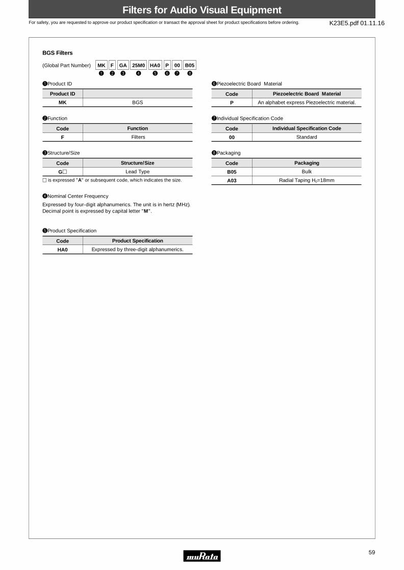
For safety, you are requested to approve our product specification or transact the approval sheet for product specifications before ordering. K23E5.pdf 01.11.16
Filters for Audio Visual EquipmentFilters for Audio Visual Equipment
59
y
P
e
GA
w
F
r
25M0
t
HA0
u
00
i
B05
q
MK(Global Part Number)
qProduct ID
wFunction
BGS Filters
MK BGS
Product ID
tProduct Specification
HA0
Code Product Specification
eStructure/Size
Bulk
Radial Taping H0=18mm
Expressed by three-digit alphanumerics.
yPiezoelectric Board Material
P
Code Piezoelectric Board Material
An alphabet express Piezoelectric material.
uIndividual Specification Code
00
Code Individual Specification Code
Standard
iPackaging
B05
A03
Code Packaging
FiltersF
Code Function
Lead TypeGp
Code Structure/Size
p is expressed "A" or subsequent code, which indicates the size.
rNominal Center Frequency
Expressed by four-digit alphanumerics. The unit is in hertz (MHz).Decimal point is expressed by capital letter "M".

For safety, you are requested to approve our product specification or transact the approval sheet for product specifications before ordering. K23E5.pdf 01.11.16
Products for Video EquipmentProducts for Video Equipment
60
qProduct ID
Focus Adjustment Resistors
MHF Focus Adjustment Blocks
Product ID
(Global Part Number)
wStyle
128
Code Style
Serial Number
eElectric Code
-24
Code Electric Code
Serial Number
rIndividual Specification Code
A
Code Individual Specification Code
An alphabet is added when other factor is specified.
e
-24
w
128
r
AMHF
q
o Part Numbering

For safety, you are requested to approve our product specification or transact the approval sheet for product specifications before ordering. K23E5.pdf 01.11.16
SensorsSensors
61
y
Q
e
18
w
F
r
AR
t
471
u
B1
i
RBPR
q
qProduct ID
wSeries
rTemperature Characteristics
yResistance Tolerance
uIndividual Specifications
PTC Thermistors (POSISTORr) Chip Type
PR PTC Thermistors Chip Type
Q
F for Overheat Sensing
AR
AS
BA
BB
BC
BD
BE
Curie Point 120°C
Curie Point 130°C
Curie Point 110°C
Curie Point 100°C
Curie Point 90°C
Curie Point 80°C
Curie Point 70°C
Special Tolerance
Temperature Characteristics
B1
Individual Specifications
Product ID
Code
Code
Code
Series
Resistance Tolerance
Code
(Global Part Number)
tResistance
Expressed by three figures. The unit is ohm (Ω). The first and second figures are signficant digits, and the third figure expresses the number of zeros which follow the two figures. If there is a decimal point, it is expressed by the capital letter "R". In this case, all figures are significant digits.
471
Ex.)
470Ω
Code Resistance
Structure, others
eDimensions (LgW)
18 1.60g0.80
Code Dimensions (LgW)
iPackaging
RB
PackagingCode
Paper Taping (4mm Pitch)
qProduct ID
eDimensions
rTemperature Characteristics
yResistance Tolerance
uIndividual Specifications
PTC Thermistors (POSISTORr) Lead Type
PT PTC Thermistors
Q04
BA
BB
BC
BD
BE
BF
BG
BH
Curie Point 110°C
Curie Point 100°C
Curie Point 90°C
Curie Point 80°C
Curie Point 70°C
Curie Point 60°C
Curie Point 50°C
Curie Point 40°C
Special Tolerance
Temperature Characteristics
2N34
Individual Specifications
Product ID
Code
Code
CodeDimensions Resistance Tolerance
Code
(Global Part Number)
tResistance
Expressed by three figures. The unit is ohm (Ω). The first and second figures are signficant digits, and the third figure expresses the number of zeros which follow the two figures. If there is a decimal point, it is expressed by the capital letter "R". In this case, all figures are significant digits.
R22
2R2
220
Ex.)
0.22Ω
2.2Ω
22Ω
Code Resistance
Lead Type, others
iPackaging
B0
PackagingCode
Bulk
Nominal Body Dimameter 4mm Series
wSeries
FL
FM
GL
for Overheat Sensing Lead Type
for Overheat Sensing with Lug-terminal
for Circuit Protection Lead Type
Code Series
u
2N34
r
BB
w
FL
t
222
y
Q
i
B0PT
q e
04
o Part Numbering

For safety, you are requested to approve our product specification or transact the approval sheet for product specifications before ordering. K23E5.pdf 01.11.16
SensorsSensors
62
qProduct ID
wSeries
tResistance Tolerance
yIndividual Specifications
NTC Thermistors Lead Type
NT NTC Thermistors
E
F
±3%
±1%
E1
Individual Specifications
Product ID
Code Resistance Tolerance
Code
(Global Part Number)
rResistance
Expressed by three figures. The unit is ohm (Ω). The first and second figures are signficant digits, and the third figure expresses the number of zeros which follow the two figures. If there is a decimal point, it is expressed by the capital letter "R". In this case, all figures are significant digits.
202
203
Ex.)
2kΩ
20kΩ
Code Resistance
Lead Style, others
SA0
SD0
for Temperature Sensors No Lead-coating Type
for Temperature Sensors Lead-coating Type
Code
uPackaging
A0
B0
Ammo Pack
Bulk
Code Packaging
Series
eTemperature Characteristics
WB
WC
WD
WF
XM
XH
XR
XV
Nominal B-Constant 4050e4099
Nominal B-Constant 4100e4149
Nominal B-Constant 4150e4199
Nominal B-Constant 4250e4299
Nominal B-Constant 3500e3549
Nominal B-Constant 3350e3399
Nominal B-Constant 3700e3749
Nominal B-Constant 3900e3949
Code Temperature Characteristics
t
F
w
SA0
e
XH
r
103
y
E1
u
B0NT
q
(Global Part Number)
qProduct ID
wType
eCharacteristics
rIndividual Specification Code
Pyroelectric Infrared Sensors
e
E710ST
w
A-
r
1
q
IR
* Global Part Number shows only an example which might be different from actual part number.* "eCharacteristics" and "rIndividual Specification Code" might have different digit number from actual Global Part Number.
(Global Part Number)
qProduct ID
wType
eCharacteristics
rIndividual Specification Code
Pyroelectric Infrared Sensor Modules
* Global Part Number shows only an example which might be different from actual part number.* "eCharacteristics" and "rIndividual Specification Code" might have different digit number from actual Global Part Number.
e
B101-
w
D-
r
01
q
IM
(Global Part Number)
qProduct ID
wSeries
eCharacteristics
rIndividual Specification Code
tPackaging
Ultrasonic Sensors
* Global Part Number shows only an example which might be different from actual part number.* Any other definitions than "qProduct ID" might have different digit numbers from actual Global Part Number.
e
14
w
40MF
r
-1N
t
-M
q
MA

For safety, you are requested to approve our product specification or transact the approval sheet for product specifications before ordering. K23E5.pdf 01.11.16
SensorsSensors
63
(Global Part Number)
qProduct ID
wSeries
eCharacteristics
rIndividual Specification Code
tPackaging
Built-in Circuit Acceleration Sensors
* Global Part Number shows only an example which might be different from actual part number.* Any other definitions than "qProduct ID" might have different digit number from actual Global Part Number.
e
60A
w
GA-S@
r t
-M
q
PK
(Global Part Number)
qProduct ID
wType
eIndividual Specification Code
rPackaging
Piezoelectric Gyroscopes (GYROSTARr)
* Global Part Number shows only an example which might be different from actual part number.* Any other definitions than "qProduct ID" might have different digit number from actual Global Part Number.
e
-02
w
C-03JA
rq
EN (Global Part Number)
qProduct ID
wType
eCharacteristics
rIndividual Specification Code
Non-contact Potentiometers
* Global Part Number shows only an example which might be different from actual part number.* Any other definitions than "qProduct ID" might have different digit number from actual Global Part Number.
e
4R1AA
w
05M
rq
LP
(Global Part Number)
qProduct ID
wType
eCharacteristics
rIndividual Specification Code
Rotary Sensors
* Global Part Number shows only an example which might be different from actual part number.* Any other definitions than "qProduct ID" might have different digit number from actual Global Part Number.
e
12AL
w
05CM
q
FR
r
(Global Part Number)
qProduct ID
wType
eCharacteristics
rIndividual Specification Code
Magnetic Pattern Recognition Sensors
* Global Part Number shows only an example which might be different from actual part number.* Any other definitions than "qProduct ID" might have different digit number from actual Global Part Number.
e
1KFAB
w
05W
q
BS
r
(Global Part Number)
qProduct ID
wSeries
eCharacteristics
rIndividual Specification Code
Electric Potential Sensors
* Global Part Number shows only an example which might be different from actual part number.* Any other definitions than "qProduct ID" might have different digit number from actual Global Part Number.
e
A
w
E05
q
PK
r
(Global Part Number)
qProduct ID
wSeries
eCharacteristics
rIndividual Specification Code
tPackaging
Shock Sensors
* Global Part Number shows only an example which might be different from actual part number.* "eCharacteristics" , "rIndividual Specification Code" and "tPackaging" might have different digit number from actual Global Part Number.
e
ME
w
GS-25
r
1
t
-R
q
PK

For safety, you are requested to approve our product specification or transact the approval sheet for product specifications before ordering. K23E5.pdf 01.11.16
Cat. No. K23E-5
Head Office2-26-10, Tenjin Nagaokakyo-shi, Kyoto 617-8555, Japan Phone:81-75-951-9111
International Division3-29-12, Shibuya, Shibuya-ku, Tokyo 150-0002, Japan Phone:81-3-5469-6123 Fax:81-3-5469-6155 E-mail:[email protected]
http://www.murata.co.jp/products/
Note:1. Export Control
<For customers outside Japan>Murata products should not be used or sold for use in the development, production, stockpiling or utilization of any conventional weapons or mass-destructiveweapons (nuclear weapons, chemical or biological weapons, or missiles), or any other weapons.<For customers in Japan>For products which are controlled items subject to the “Foreign Exchange and Foreign Trade Law” of Japan, the export license specified by the law is requiredfor export.
2. Please contact our sales representatives or product engineers before using our products listed in this catalog for the applications listed below which requireespecially high reliability for the prevention of defects which might directly cause damage to the third party's life, body or property, or when intending to use oneof our products for other applications than specified in this catalog.q Aircraft equipmentw Aerospace equipmente Undersea equipmentr Power plant equipmentt Medical equipmenty Transportation equipment (vehicles, trains, ships, etc.)u Traffic signal equipmenti Disaster prevention / crime prevention equipmento Data-processing equipment!0 Application of similar complexity and/or reliability requirements to the applications listed in the above
3. Product specifications in this catalog are as of October 2001. They are subject to change or our products in it may be discontinued without advance notice.Please check with our sales representatives or product engineers before your ordering. If there are any questions, please contact our sales representatives orproduct engineers.
4. This catalog has only typical specifications. Therefore you are requested to approve our product specification or to transact the approval sheet for productspecification, before your ordering.
5. Please note that unless otherwise specified, we shall assume no responsibility whatsoever for any conflict or dispute that may occur in connection with the effectof our and/or third party's intellectual property rights and other related rights in consideration of your using our products and/or information described orcontained in our catalogs. In this connection, no representation shall be made to the effect that any third parties are authorized to use the rights mentionedabove under licenses without our consent.
6. None of ozone depleting substances (ODS) under the Montreal Protocol is used in manufacturing process of us.