murca - murcal, the premier west coast distributor of … display active faults and ecu-stored...
TRANSCRIPT

M310-03022B page 1 of 8
DescriptionIntroducing the new M310 Series panels usingthe new PowerView System. It is available in anenclosure or stand-alone flat panel option thatcan be dropped into a dash. The PowerView is apowerful new display in a line of componentsmanufactured as part of its J1939 MurphyLink™Family. These products have been developed tomeet the needs for instrumentation and controlon electronically controlled engines communicat-ing using the SAE J1939 Controller AreaNetwork (CAN). The M310 Series Panels include the PowerViewand the Mlink™ PowerView Analog Gages. ThePowerView is a multifunction tool that enablesequipment operators to view many differentengine or transmission parameters and servicecodes. The panels provide a window into modernelectronic engines. The PowerView includes agraphical backlighted LCD screen. It has excel-lent contrast and viewing from all angles. Thedisplay can show either a single parameter or aquadrant display for viewing four parameterssimultaneously. Diagnostic capabilities includefault codes with text translation for the mostcommon fault conditions.
The PowerView has four buttons using touch-sensitive technology, which eliminates the con-cern for push button wear and failure. In additionoperators can navigate the display with ease.Enhanced alarm indication uses ultra brightalarm and shutdown LED’s (amber and red). ThePowerView has a wide operating temperaturerange of -40 to +85º C (-40 to185º F), displayviewing -40 to +75º C (-40 to 167º F), and envi-ronmental sealing to +/- 5 PSI.Other components in the panels are microproces-sor-based M-Link™ PowerView Analog Gagesfor displaying critical engine data broadcast byan electronic engine: engine RPM, oil pressure,coolant temperature, system voltage, etc. and anoptional audible alarm and relay unit for warningand shutdown annunciation. This standard panel can be ordered with or with-out an enclosure, since all of the components areassembled to a stand-a-lone flat panel. Optionalmounting kits are offered for the enclosure,which provide packagers and operators numer-ous mounting solutions to meet multiple applica-tions. Panel designs are offered to meet the needsof specific engine models. In addition,FWMurphy offers standard harnesses for quickPlug and Go operation that interface with all the2nd Generation MurphyLink™ Powerview panels.
Display ParametersThe following are some of the engine andtransmission parameters displayed by thePowerView in English or Metric units(when applicable), consult engine ortransmission manufacturer for SAE J1939supported parameters.
• Engine RPM• Engine Hours• Machine Hours• System Voltage• % Engine Load at the Current RPM• Coolant Temperature• Oil Pressure• Fuel Economy• Throttle Position• Engine Manifold Air Temperature• Current Fuel Consumption• Transmission Gear Oil Pressure• Transmission Gear Oil Temperature• Transmission Gear Position• Active Service Codes• Stored Service Codes from the Engine• Set Units for Display (English or Metric)• View Engine Configuration Parameters
M310-03022BRevised 04-04
Catalog Section 30 & 78(00-02-0533)
"Now You Know What YourEngine Is Telling You"
Standard panel designed for modern electronic enginesand equipment applications using SAE J1939 ControllerArea Network (CAN)PowerView displays over 30 standard SAE J1939 para-meters broadcast by major engine and transmissionmanufacturer’s ECU’sDisplay active faults and ECU-stored faults with textdescription on most common faults for diagnosingequipment malfunctionsStandard harnesses available for most major enginemanufacturers ECU’sEnclosed design or flat panel optionDeutsch connectors
MurphyLink™ Series M310 Panels
Typical Application Shown,Features Vary Per Engine
Application
MurphyLink 2nd
Generation Panels
MurCalCALL MURCAL TO PLACE YOUR ORDER
P:(661)272-4700 F:(661)947-7570www.murcal.com e-mail: [email protected]
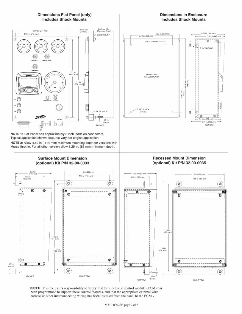
M310-03022B page 2 of 8
14 in.(356 mm)
13 in.(330 mm)
SERVICE DIAGNOSTIC
WARNING
9.50 in. (241 mm)8.50 in. (216 mm)
Dimensions Flat Panel (only)Includes Shock Mounts
Recessed Mount Dimension(optional) Kit P/N 32-00-0035
Dimensions in EnclosureIncludes Shock Mounts
NOTE 1: Flat Panel has approximately 8 inch leads on connectors.Typical application shown, features vary per engine application.NOTE 2: Allow 4.50 in.( 114 mm) minimum mounting depth for versions withMorse throttle. For all other version allow 3.25 in. (83 mm) minimum depth.
SHOCK MOUNT
See Note 2 forMounting Depth
.75 in. min(19 mm)
6.69 in(170 mm)
9 in (229 mm)5.99 in (152 mm) 9 in (229 mm)
7.50 in (190 mm)4.64 in (118 mm)7.50 in (190 mm)5.47 in
(139 mm)
16 in(406 mm)
17.10 in(434 mm)
16 in(406 mm)
17.18 in(436 mm)
SHOCK MOUNT
SIDE VIEW
FRONT VIEW
SIDE VIEW FRONT VIEW
SIDE VIEW
Surface Mount Dimension(optional) Kit P/N 32-00-0033
SHOCK MOUNT
9.93 in. (252 mm)
1.19 in. (30 mm)
7.50 in. (190 mm)
Ø .28 TYP. OF 4(7 mm)
5.15 in. (131 mm)5.91 in. (150 mm)
14.16 in.(360 m
m)
12 in.(305 m
m)
FRONT VIEWPANEL REMOVED
.25 in.(6 mm)
.25 in.(6 mm)
.25 in.(6 mm)
5.87 in. (149 mm)
NOTE : It is the user’s responsibility to verify that the electronic control module (ECM) hasbeen programmed to support these control features, and that the appropriate external wireharness or other interconnecting wiring has been installed from the panel to the ECM .
SIDE VIEW
6.62 in. (168 mm)

M310-03022B page 3 of 8
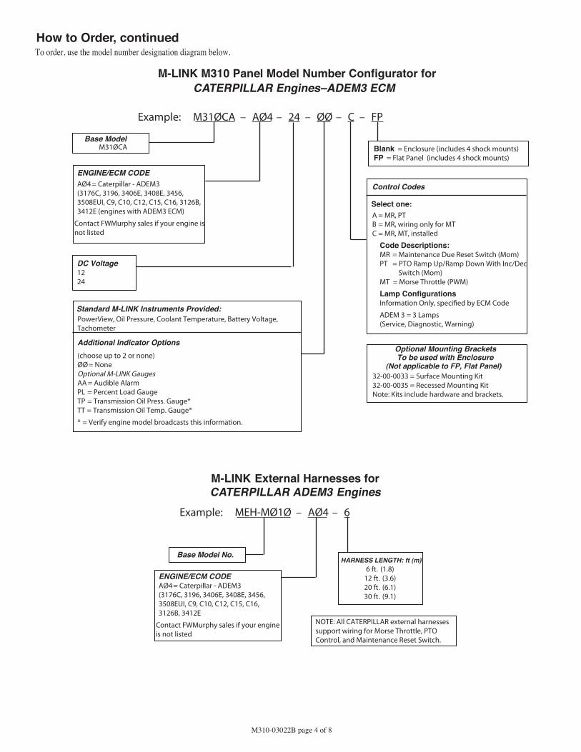
How to OrderTo order, use the model number designation diagram below.
Base Model No.M31ØCU
ENGINE/ECM CODEAØ1= Cummins QSB/QSC
(QSB5.9, QSC8.3)BØ1 = Cummins QSK
(QSK19, QSK45, QSK60)CØ1 = Cummins QSM/QSX
(QSM11, QSX15)
Contact FWMurphy sales if yourengine is not listed
HARNESS LENGTH: ft (m)6 ft. (1.8)
12 ft. (3.6)20 ft. (6.1)30 ft. (9.1)
Standard M-LINK Instruments Provided:PowerView, Oil Pressure, Coolant Temperature, Battery Voltage,Tachometer
Additional Indicator Options(choose up to 2 or none)ØØ= NoneOptional M-LINK GaugesAA = Audible AlarmPL = Percent Load GaugeTP = Transmission Oil Pressure Gauge* TT = Transmission Oil Temperature Gauge*
* = Verify engine model broadcasts this information using auxiliary J1939parameters from ECU.
*Panels not in Pricing Guide can be quoted, but may have longer lead times.
Control Codes
Select one:A = DS,IDB = DS,ID,RIC = MT,DS,ID
Code Descriptions:DS = Diagnostic Switch (Mom)ID = Increment/Decrement (Mom)RI = Run/Idle SwitchMT = Morse Throttle
Lamp Con�gurationsInformation Only, speci�ed by ECM Code
QSB/QSC = 5 Lamps(Service, Shutdown, WarningWait to Start, Water in Fuel)
QSK = 3 Lamps(Service, Shutdown, Warning)
QSM/QSX = 4 Lamps(Service, Shutdown, WarningWait to Start)
Optional Mounting BracketsTo be used with Enclosure
(Not applicable to FP, Flat Panel)32-00-0033 = Surface Mounting Kit32-00-0035 = Recessed Mounting KitNote: Kits include hardware and brackets.
Blank = Enclosure (includes 4 shock mounts)FP = Flat Panel (includes 4 shock mounts)
DC Voltage1224
Example: M31ØCU – AØ1 – 24 – ØØ– B – FP
M-LINK M310 Panel Model Number Configurator forCUMMINS Engines
Example: MEH-MØ1Ø – AØ1 – 6
M-LINK External Harnesses for CUMMINS Engines
Base Model No.
NOTE: All CUMMINS external harnessesinclude wiring for Morse Throttle, DiagnosticSwitch and Increment/Decrement Switch.
*(Please refer to Pricing Guide for available panel-models)
ENGINE/ECM CODEAØ1= Cummins QSB/QSC
(QSB5.9, QSC8.3)BØ1 = Cummins QSK
(QSK19, QSK45, QSK60)CØ1 = Cummins QSM/QSX
(QSM, QSX15)
Contact FWMurphy sales if your engine isnot listed
MurCalCALL MURCAL TO PLACE YOUR ORDER
P:(661)272-4700 F:(661)947-7570www.murcal.com e-mail: [email protected]
M310-03022B page 4 of 8
Base ModelM31ØCA
HARNESS LENGTH: ft (m)6 ft. (1.8)
12 ft. (3.6)20 ft. (6.1)30 ft. (9.1)
Control Codes
Select one:A = MR, PTB = MR, wiring only for MTC = MR, MT, installed
Code Descriptions:MR = Maintenance Due Reset Switch (Mom)PT = PTO Ramp Up/Ramp Down With Inc/Dec
Switch (Mom)MT = Morse Throttle (PWM)
Lamp ConfigurationsInformation Only, speci�ed by ECM Code
ADEM 3 = 3 Lamps(Service, Diagnostic, Warning)
DC Voltage1224
Example: M31ØCA – AØ4 – 24 – ØØ – C – FP
M-LINK M310 Panel Model Number Configurator forCATERPILLAR Engines–ADEM3 ECM
Example: MEH-MØ1Ø – AØ4 – 6
M-LINK External Harnesses for CATERPILLAR ADEM3 Engines
Base Model No.
ENGINE/ECM CODEAØ4= Caterpillar - ADEM3(3176C, 3196, 3406E, 3408E, 3456,3508EUI, C9, C10, C12, C15, C16,3126B, 3412E
Contact FWMurphy sales if your engineis not listed
How to Order, continuedTo order, use the model number designation diagram below.
NOTE: All CATERPILLAR external harnessessupport wiring for Morse Throttle, PTOControl, and Maintenance Reset Switch.
Optional Mounting BracketsTo be used with Enclosure
(Not applicable to FP, Flat Panel)32-00-0033 = Surface Mounting Kit32-00-0035 = Recessed Mounting KitNote: Kits include hardware and brackets.
Blank = Enclosure (includes 4 shock mounts)FP = Flat Panel (includes 4 shock mounts)
Standard M-LINK Instruments Provided:PowerView, Oil Pressure, Coolant Temperature, Battery Voltage,Tachometer
Additional Indicator Options(choose up to 2 or none)ØØ= NoneOptional M-LINK GaugesAA = Audible AlarmPL = Percent Load GaugeTP = Transmission Oil Press. Gauge* TT = Transmission Oil Temp. Gauge*
* = Verify engine model broadcasts this information.
ENGINE/ECM CODEAØ4= Caterpillar - ADEM3(3176C, 3196, 3406E, 3408E, 3456,3508EUI, C9, C10, C12, C15, C16, 3126B,3412E (engines with ADEM3 ECM)
Contact FWMurphy sales if your engine isnot listed

M310-03022B page 5 of 8
Engine/ECM CodeBØ3 = Perkins-1100 Series (1104, 1106)
Caterpillar-3000 Series (3054E, 3056E)
Contact FWMurphy sales if your engine is not listed
Base ModelM31ØPK
HARNESS LENGTH: ft (m)6 ft. (1.8)
12 ft. (3.6)20 ft. (6.1)30 ft. (9.1)
Control Codes
Select one:C = Single speed, no adjustE = Run/Idle speed selectF = Inc/Dec on speed
Lamp ConfigurationsInformation Only, Options C-F = 2 Lamps(Warning, Stop)
DC Voltage1224
Example: M31ØPK – BØ3 – 24 – ØØ – C – FP
M-LINK M310 Panel Model Number Configurator forPERKINS Engines–1100 Series or
CATERPILLAR–3000 Series (ADEM4 ECM)
Example: MEH-MØ1Ø – BØ3 – 6
M-LINK External Harnesses for PERKINS–1100 Series or CATERPILLAR–3000 Series (ADEM4 ECM)
Base Model No.
How to Order, continuedTo order, use the model number designation diagram below.
NOTE: All PERKINS/CATERPILLAR externalharnesses support wiring for Single Speed,Run/Idle and Increment/Decrement
Optional Mounting BracketsTo be used with Enclosure
(Not applicable to FP, Flat Panel)32-00-0033 = Surface Mounting Kit32-00-0035 = Recessed Mounting KitNote: Kits include hardware and brackets.
Blank = Enclosure (includes 4 shock mounts)FP = Flat Panel (includes 4 shock mounts)
Standard M-LINK Instruments Provided:PowerView, Oil Pressure, Coolant Temperature, Battery Voltage,Tachometer
Additional Indicator Options(choose up to 2 or none)ØØ= None
Optional M-LINK GaugesAA = Audible AlarmPL = Percent Load Gauge
ENGINE/ECM CODEBØ3** = Perkins - 1100 Series
(1104, 1106)Caterpillar - 3000 Series
(3054E, 3056E)
**HARNESS REQUIRES RELAY(S) SEEBELOW
Contact FWMurphy sales if your engineis not listed
**HARNESS REQUIRES RELAY(S)(BØ3)
00008799 = 12V Relay [1104/3054E (2) Required, 1106/3056E (1) Required]00008800 = 24V Relay [1104/3054E (2) Required, 1106/3056E (1) Required]
NOTE: Relays sold separately. Relays must have minimum 30 amp contact rating.
MurCalCALL MURCAL TO PLACE YOUR ORDER
P:(661)272-4700 F:(661)947-7570www.murcal.com e-mail: [email protected]
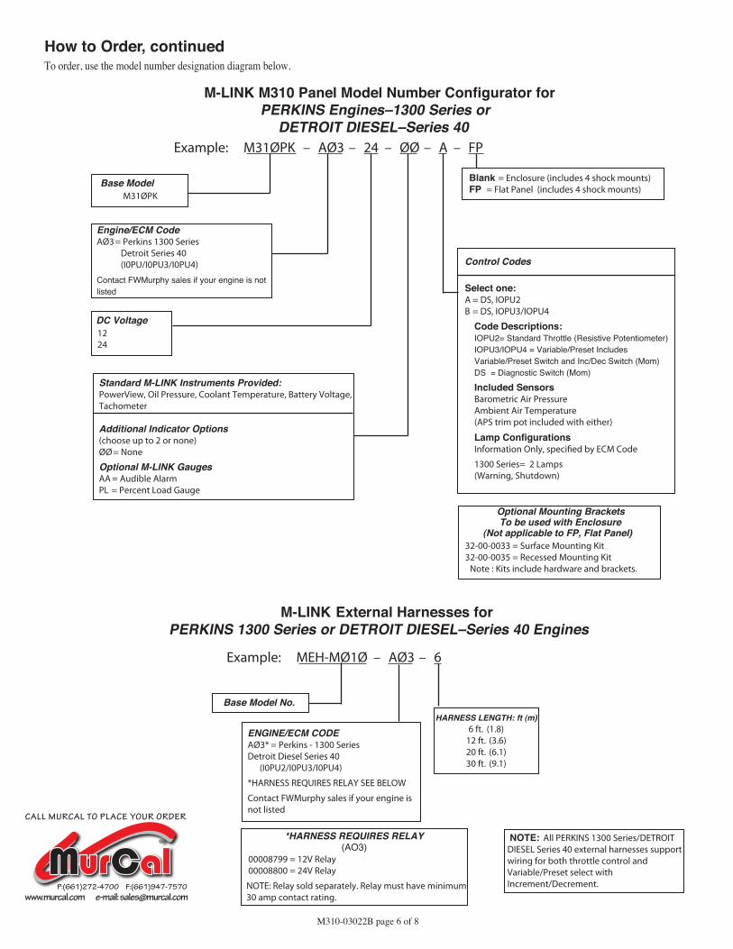
M310-03022B page 6 of 8
Engine/ECM CodeAØ3= Perkins 1300 Series
Detroit Series 40(I0PU/I0PU3/I0PU4)
Contact FWMurphy sales if your engine is notlisted
Base ModelM31ØPK
HARNESS LENGTH: ft (m)6 ft. (1.8)
12 ft. (3.6)20 ft. (6.1)30 ft. (9.1)
Control Codes
Select one:A = DS, IOPU2B = DS, IOPU3/IOPU4
Code Descriptions:IOPU2= Standard Throttle (Resistive Potentiometer)IOPU3/IOPU4 = Variable/Preset IncludesVariable/Preset Switch and Inc/Dec Switch (Mom)DS = Diagnostic Switch (Mom)
Included SensorsBarometric Air PressureAmbient Air Temperature(APS trim pot included with either)
Lamp ConfigurationsInformation Only, speci�ed by ECM Code
1300 Series= 2 Lamps(Warning, Shutdown)
DC Voltage1224
Example: M31ØPK – AØ3 – 24 – ØØ – A – FP
M-LINK M310 Panel Model Number Configurator forPERKINS Engines–1300 Series or
DETROIT DIESEL–Series 40
Example: MEH-MØ1Ø – AØ3 – 6
M-LINK External Harnesses for PERKINS 1300 Series or DETROIT DIESEL–Series 40 Engines
Base Model No.
How to Order, continuedTo order, use the model number designation diagram below.
NOTE: All PERKINS 1300 Series/DETROITDIESEL Series 40 external harnesses supportwiring for both throttle control andVariable/Preset select withIncrement/Decrement.
Optional Mounting BracketsTo be used with Enclosure
(Not applicable to FP, Flat Panel)32-00-0033 = Surface Mounting Kit32-00-0035 = Recessed Mounting Kit
Note : Kits include hardware and brackets.
Blank = Enclosure (includes 4 shock mounts)FP = Flat Panel (includes 4 shock mounts)
Standard M-LINK Instruments Provided:PowerView, Oil Pressure, Coolant Temperature, Battery Voltage,Tachometer
Additional Indicator Options(choose up to 2 or none)ØØ= None
Optional M-LINK GaugesAA = Audible AlarmPL = Percent Load Gauge
ENGINE/ECM CODEAØ3* = Perkins - 1300 SeriesDetroit Diesel Series 40
(I0PU2/I0PU3/I0PU4)
*HARNESS REQUIRES RELAY SEE BELOW
Contact FWMurphy sales if your engine isnot listed
*HARNESS REQUIRES RELAY(AO3)
00008799 = 12V Relay 00008800 = 24V Relay
NOTE: Relay sold separately. Relay must have minimum30 amp contact rating.
MurCalCALL MURCAL TO PLACE YOUR ORDER
P:(661)272-4700 F:(661)947-7570www.murcal.com e-mail: [email protected]

M310-03022B page 7 of 8
Engine/ECM CodeAØ2= DD50/60 Series
(DDEC III, DDEC IV)BØ2 = DD 2000 Series
(DDEC III, DDEC IV)
Contact FWMurphy sales if your engine is notlisted
Base ModelM31ØDD
ENGINE/ECM CODEAØ2= DETROIT DIESEL 50/60, 2000 Series
(DDEC III, DDEC IV)
Contact FWMurphy sales if your engine isnot listed
HARNESS LENGTH: ft (m)6 ft. (1.8)
12 ft. (3.6)20 ft. (6.1)30 ft. (9.1)
Control Codes
Select one:A = DS, MTB = ES, DS, MT
Code Descriptions:MT = Analog Morse ThrottleDS = Diagnostic Switch (Mom)ES = Emergency Stop Switch
Lamp ConfigurationsInformation Only, speci�ed by ECM Code
DDEC III, IV= 2 Lamps(Stop Engine, Check Engine)
DC Voltage1224
Example: M31ØDD – AØ2 – 24 – ØØ – B – FP
M-LINK M310 Panel Model Number Configurator forDETROIT DIESEL Engines–Series 50/60 and Series 2000
Example: MEH-MØ1Ø – AØ2 – 6
M-LINK External Harnesses for DETROIT DIESEL–Series 50/60 and Series 2000
Base Model No.
How to Order, continuedTo order, use the model number designation diagram below.
NOTE: DETROIT DIESEL external harnessessupport wiring for Morse throttle control andsupports the emergency-stop panel
Standard M-LINK Instruments Provided:PowerView, Oil Pressure, Coolant Temperature, Battery Voltage,Tachometer
Additional Indicator Options(choose up to 2 or none)ØØ= None
Optional M-LINK GaugesAA = Audible AlarmPL = Percent Load Gauge
Optional Mounting BracketsTo be used with Enclosure
(Not applicable to FP, Flat Panel)32-00-0033 = Surface Mounting Kit32-00-0035 = Recessed Mounting KitNote: Kits include hardware and brackets.
Blank = Enclosure (includes 4 shock mounts)FP = Flat Panel (includes 4 shock mounts)
MurCalCALL MURCAL TO PLACE YOUR ORDER
P:(661)272-4700 F:(661)947-7570www.murcal.com e-mail: [email protected]

M310-03022B page 8 of 8
REGISTERED
USA–ISO 9001:2000 FM 28221UK–ISO 9001:2000 FM 29422
Printed in U.S.A.
WarrantyA limited warranty on materials and workmanship is given with this FW Murphy product.
A copy of the warranty may be viewed or printed by going to www.fwmurphy.com/support/warranty.htm
MurCalCALL MURCAL TO PLACE YOUR ORDER
P:(661)272-4700 F:(661)947-7570www.murcal.com e-mail: [email protected]