murfi 2016 - from cars to mars: applying autonomous ...mobile/papers/2017astra_yeomans.pdf · murfi...
TRANSCRIPT

MURFI 2016 - FROM CARS TO MARS: APPLYING AUTONOMOUS VEHICLENAVIGATION METHODS TO A SPACE ROVER MISSION
Brian Yeomans1, Horia Porav1, Matthew Gadd1, Dan Barnes1, Julie Dequaire1, Tom Wilcox1, Stephen Kyberd1,Simon Venn1, and Paul Newman1
1Oxford Robotics Institute, University of Oxford, United Kingdom{brian,horia,mattgadd,dbarnes,julie,tomw,skyberd,svenn,pnewman}@robots.ox.ac.uk
ABSTRACT
The Mars Utah Rover Field Investigation (MURFI) 2016mission was a Mars Rover field analogue mission run bythe UK Space Agency (UKSA) in collaboration with theCanadian Space Agency (CSA). MURFI consisted of a“field team” at the Mars analogue site near Hanksville(Utah, USA), and an “Operations Team” based in theMission Operations Centre (MOC) at UKSA’s HarwellCampus (Oxfordshire, UK).
The Rover platform for the mission comprised the Ox-ford Robotics Institute’s (ORI) ARC Q14 Space Rover(Q14), and the mission provided a unique opportunity forORI to test the performance of several of their advancednavigation and autonomous driving algorithms in realisticplanetary exploration conditions over a period of severalweeks (Figure 1). MURFI’s core objectives included arealistic imitation of the first 10 sols of a possible futureMars Rover mission.
Following completion of the core mission, the ORI Roverteam engaged in a series of ambitious trials and data gath-ering scenarios based on ORI’s broad suite of navigationand autonomy algorithms which have been developed pri-marily for on-road terrestrial applications. The objectiveswere to (i) assess the performance of these systems inthis radically different environment, (ii) determine whatsystems modifications (if any) might be needed to op-erate effectively in a typical planetary surface scenario,and (iii) to identify which new capabilities these tech-niques might bring to the field of planetary surface nav-igation and exploration. The results of these trials werevery encouraging, showing good baseline performance ofthe techniques deployed even though these had not beenmodified in any way to reflect the change of environment,and indicating several avenues for further exploration anddevelopment of ORI’s techniques which could generatesubstantial benefits for the Space community.
During the core mission, the Rover drives for eachsol were conducted autonomously using a single mast-mounted stereo camera sensor. Waypoint files for theplanned drives were designed by the MOC, transmitted tothe field site, and uploaded to Q14 for autonomous execu-
tion using ORI’s OxfordVO visual odometry (VO) appli-cation - the same application which forms the kernel ofthe VO software for the forthcoming ExoMars mission.The accuracy in following the planned drives during thisphase was highly satisfactory, with the Rover typicallyfinishing the drive within a few centimetres of the plannedlocation.
During the post-MURFI trials programme, the team im-plemented ORI’s “Dub4” suite to provide “teach-and-repeat” (T&R) functionality. Dub4 uses a single stereocamera to create vision-based maps in highly unstruc-tured environments which are then used to localise andnavigate autonomously. This facilitates safe, rapid re-tracing of a previously driven path, enabling interestingscience sites subsequently identified through data analy-sis to be rapidly revisited by the Rover. Accuracy in fol-lowing the previously driven path was good despite largeareas of the driven environment being relatively feature-less. The use of an affordable monocular camera as aneffective localisation sensor using the feature-rich desertfloor was investigated, with encouraging results. Datawas collected so that dense reconstructions of the terrainaround the rover can be generated in a future phase ofour work. This reconstruction capability has the poten-tial to create an extremely powerful visualisation tool forgenerating rich 3-D mesh representations to be utilisedby mission scientists to more effectively focus the sci-ence effort. Future work will also concentrate on per-formance enhancements by adapting existing ORI tech-niques to the specifics of the planetary surface environ-ment, and developing enhanced machine learning auton-omy approaches along the path towards the implementa-tion of a true “robot geologist”.
Key words: robots; rover; localisation; mapping; auton-omy; teach-and-repeat.
1. INTRODUCTION
The MURFI mission was a rover field mission intendedto demonstrate the capability of the UKSA, in collabo-ration with international partners including the CSA, to
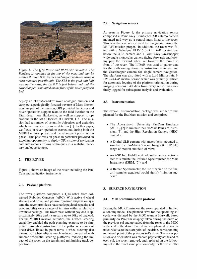
Figure 1. The Q14 Rover and PANCAM emulator. ThePanCam is mounted at the top of the mast and can berotated through 360 degrees and angled up/down using amast mounted pan/tilt unit. The XB3 is the gold unit halfway up the mast, the LIDAR is just below, and and theGrasshopper is mounted on the front of the rover platformbed.
deploy an “ExoMars-like” rover analogue mission andcarry out a geologically-focused traverse of Mars-like ter-rain. As part of the mission, ORI provided the Rover androver operations support team to the field location in theUtah desert near Hanksville, as well as support to op-erations in the MOC located at Harwell, UK. The mis-sion had a number of scientific objectives and activitieswhich are described in more detail in [1]. In this paper,we focus on rover operations carried out during both theMURFI mission proper, and the subsequent post-missionphase. This post-mission phase in particular provided anexcellent opportunity to deploy ORI’s suite of navigationand autonomous driving techniques in a realistic plane-tary analogue context.
2. THE ROVER
Figure 1 shows an image of the rover including the Pan-Cam and navigation instruments.
2.1. Payload platform
The rover platform comprised a Q14 robot from Ad-vanced Robotics Concepts (ARC). With active 4-wheelsteering and drive, and passive dynamic suspension sys-tem, the rover provides a reasonable payload capacity andgood mobility over a range of terrains within a relativelylow mass package. The rover mass without payload is ap-proximately 30kg and it can carry up to 40kg of payload.For the MURFI mission activities, the 4-wheel steeringcapability enabled the path planning exercise to be sim-plified through construction of the paths as a series oflinear drives linked by point turns. 4-wheel steering alsomeans that wheel-slip is much reduced compared withsimpler differential steering platforms, reducing the im-pact of the rover on the terrain and minimising track de-position.
2.2. Navigation sensors
As seen in Figure 1, the primary navigation sensorcomprised a Point Grey Bumblebee XB3 stereo cameramounted mid-way up a central mast fitted to the rover.This was the sole sensor used for navigation during theMURFI mission proper. In addition, the rover was fit-ted with a Velodyne VLP-16 3-D LIDAR located justbelow the XB3 camera and a Point Grey Grasshopperwide-angle monocular camera facing forwards and look-ing past the forward wheel set towards the terrain infront of the rover. The LIDAR was used to gather datafor the forthcoming dense reconstruction exercises, andthe Grasshopper camera for single-camera navigation.The platform was also fitted with a Lord Microstrain 3-DM-GX4-45 inertial sensor, which was primarily utilisedfor automatic logging of the platform orientation duringimaging sessions. All data from every sensor was rou-tinely logged for subsequent analysis and evaluation.
2.3. Instrumentation
The overall instrumentation package was similar to thatplanned for the ExoMars mission and comprised:
• The Aberystwyth University PanCam Emulator(AUPE) [2] to simulate the ExoMars PanCam instru-ment [3], and the High Resolution Camera (HRC)emulator,
• A Digital SLR camera with macro lens, mounted tosimulate the ExoMars Close-up Imager (CLUPI [4])range of motion and field-of-view,
• An ASD Inc. FieldSpec4 field reflectance spectrom-eter to simulate the Infrared Spectrometer for MarsInstrument (ISEM, [5]), and
• A Raman Spectrometer, the use of which on the finaldrill-samples acquired would signify “mission suc-cess”.
3. SURFACE NAVIGATION
3.1. MOC communication protocol
During the MURFI mission, the rover operated in limitedautonomy mode. The planned drive for the upcoming solcycle was dictated by the MOC team at Harwell, basedprimarily on PanCam imagery taken during the drive onthe previous sol and uploaded from the rover to the MOCat the end of the drive. Each drive was planned in coordi-nates relative to the start point of the drive, correspondingto the end point of the previous sol’s drive. The rover po-sition and orientation was marked physically at the end ofeach sol, the rover removed, and replaced on the follow-ing sol in the exact same position ready for the drive. The

planned drive was described simply as the (x, y) coordi-nates in metres relative to the start position of a series ofwaypoints linked by point turns. The orientation at eachpoint turn was specified, including the goal orientation.A text descriptor file was generated by the MOC, sent tothe field team, and uploaded to the rover.
3.2. Executing sol drives
When driving, the rover operated autonomously. To en-sure the rover actually drove the planned track, the roverutilised the XB3 stereo camera linked to OxfordVO [6],which generated frame-by-frame estimates of Q14’s ego-motion. This application has been selected as the VOcomponent for the forthcoming ExoMars mission, and isdescribed in more detail in [7].
Using a simple differential controller which calculatedthe difference between the rover’s actual and plannedpose, corrections were generated to ensure the rover ad-hered to the planned path. The system performance wasfound to be excellent, with the actual position at the endof each sol’s drive measured to be within just a few cen-timetres of the planned position, and no problems wereexperienced in meeting the MURFI mission rover driverequirements.
4. TEACH-AND-REPEAT WITH DUB4
“Wherever, Whenever, Whatever the Weather” (Dub4) isORI’s state-of-the-art visual navigation system. In thissection we describe an approach where the rover is firstmanually driven along a path (“teach”) and then subse-quently drives that same path autonomously (“repeat”).To do this, Dub4 consumes live images from a stereocamera and compares them to a database of previouslyrecorded locations to determine the precise position ofthe rover with respect to the “taught” path [8][9][10].
4.1. Mapping
The database is created during a first survey of the rover’sroute (an experience) by storing both visual snapshots ofthe places that it sees and the relative coordinates (rota-tion, translation) between these snapshots. As the roverundertakes more drives, many more experiences of ei-ther the same route or of different routes can be addedand fused together seamlessly in order to improve thelocalisation performance of the rover, and this accumu-lated database of information can then be used to lo-calise the rover under a diversity of viewpoint, illumina-tion, and weather conditions. The rover finds its positionalong the route by first determining which visual snap-shot (keyframe) matches best with what is currently ob-served, and then computing a metric 6DoF pose relativeto that snapshot. The rover can then compute its rela-tive position against any other snapshot recorded in the
database by examining the chain of stored poses betweensnapshots [8][9][10].
First, the rover’s trajectory is estimated using VO[11][12]: the current stereo image pair Ft is used to cre-ate and store a bank of 3-D landmarks (SURF, BRIEF,ORB), and a 6-Degree-of-Freedom (6DoF) transforma-tion is computed between Ft and the previous stereo pair,Ft−1. The 3-D landmarks and 6DoF poses between themare stored in an “experience” graph G, with nodes com-posed of 3-D landmarks and the 6DoF transforms savedas edges between nodes (see Figure 2), under the as-sumption that 6DoF transforms between nodes that areclose will be metrically accurate, while nodes that arefar away from each other will maintain only a topologi-cal ordering [13][14][8]. At localisation time, landmarksextracted from Ft are compared against the stored 3-Dlandmarks, and a 6DoF transform is computed betweenFt and the experience frame Fexpi that best matches thecurrent frame.
4.2. Localisation
During localisation, the rover’s pose is encoded as a ref-erence node Ni and a 6DoF transform TNi,Rt
betweenthe rover and this reference node. Localisation is a two-step process: Firstly, large-scale localisation (so calledplace-recognition) is done using FABMAP [15], whichdetects loop-closures using image similarity and yieldsa set of candidate nodes Ni that are most similar to thelive frame, without actually computing a pose relative toany of those nodes. Secondly, local-scale metric local-isation is performed on these candidate nodes, by solv-ing for a 6DoF transform between each candidate nodeand the live frame. Finally, Dub4 will output a 6DoFtransform with respect to the node that has the most in-liers(correct landmark correspondences between the liveframe and the keyframe stored on the node).
4.3. Path memory
However, the number of nodes that need to be checked byFABMAP will grow with each added experience, whichmight become problematic, especially when running onresource-constrained hardware such as a rover. Giventhat localisation must run in real-time or near-real-time,a naı̈ve approach would only be able to check a reducednumber of experience nodes before the next live frameis fed into the system. To increase the probability of lo-calisation success under these constraints, Dub4 uses aranking policy [8] which sorts the candidate experiencenodes by their distance to the current position estimateobtained using VO. Additionally, Dub4 ranks candidatenodes based on which experience is currently used for lo-calisation, as it is likely that the same experience will beused to localise in future frames. This probabilistic ap-proach is further explained in [8] and [16].
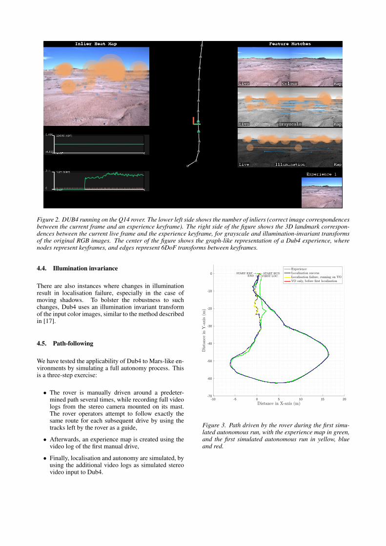
Figure 2. DUB4 running on the Q14 rover. The lower left side shows the number of inliers (correct image correspondencesbetween the current frame and an experience keyframe). The right side of the figure shows the 3D landmark correspon-dences between the current live frame and the experience keyframe, for grayscale and illumination-invariant transformsof the original RGB images. The center of the figure shows the graph-like representation of a Dub4 experience, wherenodes represent keyframes, and edges represent 6DoF transforms between keyframes.
4.4. Illumination invariance
There are also instances where changes in illuminationresult in localisation failure, especially in the case ofmoving shadows. To bolster the robustness to suchchanges, Dub4 uses an illumination invariant transformof the input color images, similar to the method describedin [17].
4.5. Path-following
We have tested the applicability of Dub4 to Mars-like en-vironments by simulating a full autonomy process. Thisis a three-step exercise:
• The rover is manually driven around a predeter-mined path several times, while recording full videologs from the stereo camera mounted on its mast.The rover operators attempt to follow exactly thesame route for each subsequent drive by using thetracks left by the rover as a guide,
• Afterwards, an experience map is created using thevideo log of the first manual drive,
• Finally, localisation and autonomy are simulated, byusing the additional video logs as simulated stereovideo input to Dub4.
-10 -5 0 5 10 15 20-70
-60
-50
-40
-30
-20
-10
0
Figure 3. Path driven by the rover during the first simu-lated autonomous run, with the experience map in green,and the first simulated autonomous run in yellow, blueand red.
0 2 4 60
10
20
30
40
0 2 40
10
20
30
40
0 2 4 60
20
40
60
0 2 40
20
40
60
0 1 2 30
10
20
30
40
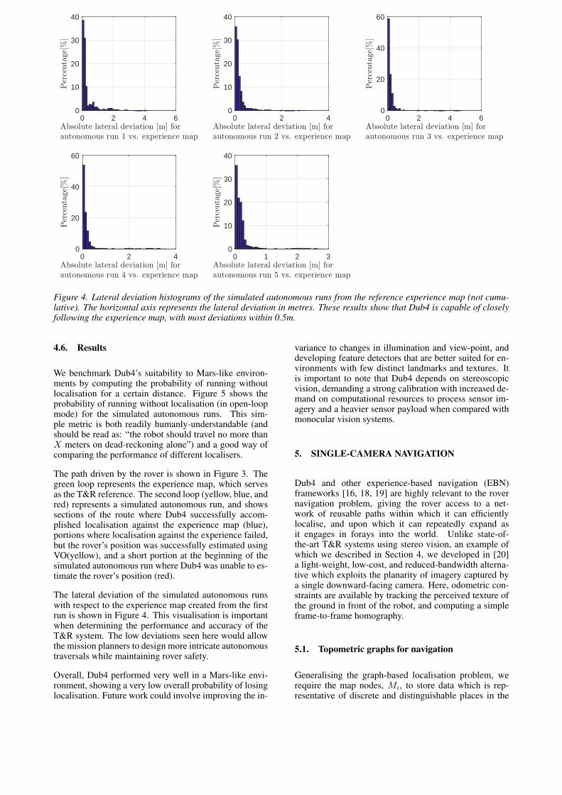
Figure 4. Lateral deviation histograms of the simulated autonomous runs from the reference experience map (not cumu-lative). The horizontal axis represents the lateral deviation in metres. These results show that Dub4 is capable of closelyfollowing the experience map, with most deviations within 0.5m.
4.6. Results
We benchmark Dub4’s suitability to Mars-like environ-ments by computing the probability of running withoutlocalisation for a certain distance. Figure 5 shows theprobability of running without localisation (in open-loopmode) for the simulated autonomous runs. This sim-ple metric is both readily humanly-understandable (andshould be read as: “the robot should travel no more thanX meters on dead-reckoning alone”) and a good way ofcomparing the performance of different localisers.
The path driven by the rover is shown in Figure 3. Thegreen loop represents the experience map, which servesas the T&R reference. The second loop (yellow, blue, andred) represents a simulated autonomous run, and showssections of the route where Dub4 successfully accom-plished localisation against the experience map (blue),portions where localisation against the experience failed,but the rover’s position was successfully estimated usingVO(yellow), and a short portion at the beginning of thesimulated autonomous run where Dub4 was unable to es-timate the rover’s position (red).
The lateral deviation of the simulated autonomous runswith respect to the experience map created from the firstrun is shown in Figure 4. This visualisation is importantwhen determining the performance and accuracy of theT&R system. The low deviations seen here would allowthe mission planners to design more intricate autonomoustraversals while maintaining rover safety.
Overall, Dub4 performed very well in a Mars-like envi-ronment, showing a very low overall probability of losinglocalisation. Future work could involve improving the in-
variance to changes in illumination and view-point, anddeveloping feature detectors that are better suited for en-vironments with few distinct landmarks and textures. Itis important to note that Dub4 depends on stereoscopicvision, demanding a strong calibration with increased de-mand on computational resources to process sensor im-agery and a heavier sensor payload when compared withmonocular vision systems.
5. SINGLE-CAMERA NAVIGATION
Dub4 and other experience-based navigation (EBN)frameworks [16, 18, 19] are highly relevant to the rovernavigation problem, giving the rover access to a net-work of reusable paths within which it can efficientlylocalise, and upon which it can repeatedly expand asit engages in forays into the world. Unlike state-of-the-art T&R systems using stereo vision, an example ofwhich we described in Section 4, we developed in [20]a light-weight, low-cost, and reduced-bandwidth alterna-tive which exploits the planarity of imagery captured bya single downward-facing camera. Here, odometric con-straints are available by tracking the perceived texture ofthe ground in front of the robot, and computing a simpleframe-to-frame homography.
5.1. Topometric graphs for navigation
Generalising the graph-based localisation problem, werequire the map nodes, Mi, to store data which is rep-resentative of discrete and distinguishable places in the

0 0.5 1 1.5 2 2.5 30
0.05
0.1
0.15
Figure 5. Probability of running without localisation (inopen-loop mode) for the simulated autonomous runs. Thehorizontal axis represents the distance travelled in open-loop. The vertical axis represents the probability of trav-elling a certain distance in open-loop mode.
world (e.g. image, laser scan, etc). An edge betweennodes i and j must characterise a relationship betweenplaces iφj . To search, we must be able to composethe edge constraints iφk = iφj ⊕ jφk . . ., along a pathP = {iφj , jφk, . . .} in the database. Finally, to decide iftwo places are close together, we need some symmetricalmetric |iφj | = |jφi| ≥ 0.
5.2. Frame-to-frame edge constraints
As the robot moves (from time k − 1 to k), it will ob-serve a point of interest (in 3-D space) at slightly dif-ferent image coordinates xk−1 and xk, due to its mo-tion. If this point is on or near an approximately planarsurface, the image coordinates are related by a (3 × 3)matrix (called a planar-induced homography) such thatxk = Hk,k−1xk−1. For every pair of frames that therover observes as it moves, we can estimate this homog-raphy by iteratively discarding points not on the plane ina RANSAC process [21]. Examples of these interestingimage pixels are shown in Figure 6, including many out-liers (e.g. points on the horizon) that need to be filteredby the estimation process.
5.3. Characterising places
Originally, we detected and matched interesting pointsusing speeded-up robust features (SURF) [22], due to itsrobustness to viewpoint changes, and broad support in the
Figure 6. Sample imagery showing interesting features(detected and described by SURF) on two subsequent im-ages captured by the rover as it moves, and matches fromframe-to-frame
software community. However, this framework leaves thedesigner free to choose place characterisation and con-nectivity. Indeed, we have successfully integrated GPUacceleration [23] and a fast binary descriptor [24].
5.4. Localisation
Having populated the database with an initial mappingrun, localisation is then achieved by optimising the met-ric for “closeness” over the set of nodes in a modest(in terms of total edges traversed) graph neighbourhoodM = {m | ρ−σ ≤ m ≤ ρ+σ} around the current pose,ρ, which can be obtained by an arbitrary graph search al-gorithm (e.g. breadth-first, depth-first). Candidates forthis metric may include a distance in homography-space(see [25]), or the overlap of the two images when the ho-mography is used to warp one of them.
5.5. Recovering motion
While localisation in this example is achieved purely inthe space of homographies, it is possible to recover therotation and (up-to-scale) translation, as the homogra-phy decomposes to Hk,k−1 = Rk−1,k + 1
dtk−1,knπT .
For this, the intrinsic camera parameters (distortion, etc)and a singular-value decomposition (SVD) are required(see [26]). Furthermore, if the camera height is well cali-brated, the absolute scale of the motion is available.
5.6. Experiments
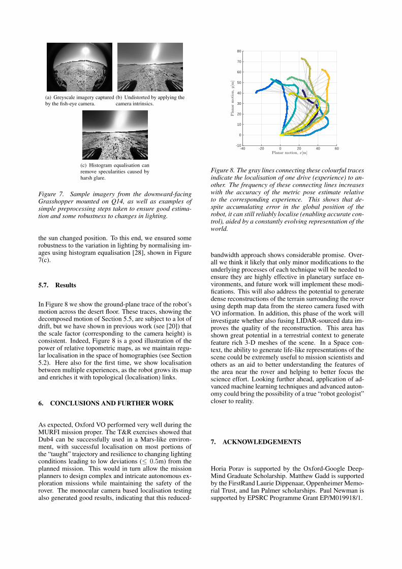
We tested this system by repeatedly driving Q14 arounda highly textured and somewhat flat area near the MURFIbase. As shown in Figure 7(a), the greyscale imagery wascaptured by a Point Grey Grasshopper monocular cameraat resolution 1036 × 1084. The camera’s intrinsics wereused to rectify images (Figure 7(b)) and was computedusing the OCamCalib toolbox [27]. The route was pilotedat regular intervals (8 traverses) over a period of 24 hours,totalling approximately 800m. As such, the data presentus with variation in environmental appearance, predomi-nantly due to the waxing and waning of available light as
(a) Greyscale imagery capturedby the fish-eye camera.
(b) Undistorted by applying thecamera intrinsics.
(c) Histogram equalisation canremove specularities caused byharsh glare.
Figure 7. Sample imagery from the downward-facingGrasshopper mounted on Q14, as well as examples ofsimple preprocessing steps taken to ensure good estima-tion and some robustness to changes in lighting.
the sun changed position. To this end, we ensured somerobustness to the variation in lighting by normalising im-ages using histogram equalisation [28], shown in Figure7(c).
5.7. Results
In Figure 8 we show the ground-plane trace of the robot’smotion across the desert floor. These traces, showing thedecomposed motion of Section 5.5, are subject to a lot ofdrift, but we have shown in previous work (see [20]) thatthe scale factor (corresponding to the camera height) isconsistent. Indeed, Figure 8 is a good illustration of thepower of relative topometric maps, as we maintain regu-lar localisation in the space of homographies (see Section5.2). Here also for the first time, we show localisationbetween multiple experiences, as the robot grows its mapand enriches it with topological (localisation) links.
6. CONCLUSIONS AND FURTHER WORK
As expected, Oxford VO performed very well during theMURFI mission proper. The T&R exercises showed thatDub4 can be successfully used in a Mars-like environ-ment, with successful localisation on most portions ofthe “taught” trajectory and resilience to changing lightingconditions leading to low deviations (≤ 0.5m) from theplanned mission. This would in turn allow the missionplanners to design complex and intricate autonomous ex-ploration missions while maintaining the safety of therover. The monocular camera based localisation testingalso generated good results, indicating that this reduced-
Planar motion, x[m]-40 -20 0 20 40 60
Pla
nar
motion,y[m
]
-10
0
10
20
30
40
50
60
70
80
Figure 8. The gray lines connecting these colourful tracesindicate the localisation of one drive (experience) to an-other. The frequency of these connecting lines increaseswith the accuracy of the metric pose estimate relativeto the corresponding experience. This shows that de-spite accumulating error in the global position of therobot, it can still reliably localise (enabling accurate con-trol), aided by a constantly evolving representation of theworld.
bandwidth approach shows considerable promise. Over-all we think it likely that only minor modifications to theunderlying processes of each technique will be needed toensure they are highly effective in planetary surface en-vironments, and future work will implement these modi-fications. This will also address the potential to generatedense reconstructions of the terrain surrounding the roverusing depth map data from the stereo camera fused withVO information. In addition, this phase of the work willinvestigate whether also fusing LIDAR-sourced data im-proves the quality of the reconstruction. This area hasshown great potential in a terrestrial context to generatefeature rich 3-D meshes of the scene. In a Space con-text, the ability to generate life-like representations of thescene could be extremely useful to mission scientists andothers as an aid to better understanding the features ofthe area near the rover and helping to better focus thescience effort. Looking further ahead, application of ad-vanced machine learning techniques and advanced auton-omy could bring the possibility of a true “robot geologist”closer to reality.
7. ACKNOWLEDGEMENTS
Horia Porav is supported by the Oxford-Google Deep-Mind Graduate Scholarship. Matthew Gadd is supportedby the FirstRand Laurie Dippenaar, Oppenheimer Memo-rial Trust, and Ian Palmer scholarships. Paul Newman issupported by EPSRC Programme Grant EP/M019918/1.

REFERENCES
[1] Balme et al. Mars Utah Rover Field Investigation2016 (MURFI 2016): Overview of Mission, Aimsand Progress. Lunar and Planetary Science XLVIII,2017.
[2] Harris et al. Remote detection of past habitabil-ity at Mars-analogue hydrothermal alteration ter-rains using an ExoMars Panoramic Camera emula-tor. Icarus, 252:284–300, 2015.
[3] Coates et al. The PanCam instrument for the Exo-Mars rover. Astrobiology, in press, 2017.
[4] Josset et al. The Close-Up Imager (CLUPI) onboard the ESA ExoMars Rover: Objectives, de-scription, operations, and science validation activ-ities. Astrobiology, in press, 2017.
[5] Koroblev et al. Infrared spectrometer for ExoMars(ISEM), a mast-mounted instrument for the rover.Astrobiology, in press, 2017.
[6] Winston Churchill. Experience Based Navigation:Theory, Practice and Implementation. PhD the-sis, University of Oxford, Oxford, United Kingdom,2012.
[7] Shaw et al. Robust visual odometry for space explo-ration. Advanced Space Technologies in Roboticsand Automation, 2013.
[8] Linegar et al. Work Smart, Not Hard: Recall-ing Relevant Experiences for Vast-Scale but Time-Constrained Localisation. In Proceedings of theIEEE International Conference on Robotics and Au-tomation (ICRA), Seattle, WA, USA, May 2015.
[9] Linegar et al. Made to measure: Bespoke landmarksfor 24-hour, all-weather localisation with a camera.In Proceedings of the IEEE International Confer-ence on Robotics and Automation (ICRA), Stock-holm, Sweden, May 2016.
[10] Nelson et al. Building, Curating, and QueryingLarge-scale Data Repositories for Field RoboticsApplications. In International Conference on Fieldand Service Robotics (FSR), Toronto, ON, Canada,June 2015.
[11] Maimone et al. Two years of visual odometry on themars exploration rovers. Journal of Field Robotics,24(3):169–186, 2007.
[12] Nister et al. Visual odometry for ground vehicleapplications. Journal of Field Robotics, 23(1):3–20,2006.
[13] Sibley et al. Planes, trains and automobiles: Auton-omy for the modern robot. In Robotics and Automa-tion (ICRA), 2010 IEEE International Conferenceon, pages 285–292. IEEE, 2010.
[14] Strasdat et al. Double window optimisation for con-stant time visual slam. In 2011 International Con-ference on Computer Vision, pages 2352–2359, Nov2011.
[15] Mark Cummins and Paul Newman. Appearance-only slam at large scale with fab-map 2.0. The Inter-national Journal of Robotics Research, 30(9):1100–1123, 2011.
[16] Winston Churchill and Paul Newman. Experience-based navigation for long-term localisation. TheInternational Journal of Robotics Research,32(14):1645–1661, 2013.
[17] McManus et al. Shady dealings: Robust, long-termvisual localisation using illumination invariance. InRobotics and Automation (ICRA), 2014 IEEE In-ternational Conference on, pages 901–906. IEEE,2014.
[18] Maddern et al. Leveraging Experience for Large-Scale LIDAR Localisation in Changing Cities. InProceedings of the IEEE International Conferenceon Robotics and Automation (ICRA), Seattle, WA,USA, May 2015.
[19] Michael J Milford and Gordon F Wyeth. Seqs-lam: Visual route-based navigation for sunny sum-mer days and stormy winter nights. In Robotics andAutomation (ICRA), 2012 IEEE International Con-ference on, pages 1643–1649. IEEE, 2012.
[20] Matthew Gadd and Paul Newman. A frameworkfor infrastructure-free warehouse navigation. InProceedings of the IEEE International Conferenceon Robotics and Automation (ICRA), Seattle, WA,USA, May 2015.
[21] Martin A Fischler and Robert C Bolles. Ran-dom sample consensus: a paradigm for model fit-ting with applications to image analysis and auto-mated cartography. Communications of the ACM,24(6):381–395, 1981.
[22] Bay et al. SURF: Speeded up robust features. Com-puter vision–ECCV 2006, pages 404–417, 2006.
[23] Pulli et al. Real-time computer vision with opencv.Communications of the ACM, 55(6):61–69, 2012.
[24] Rublee et al. Orb: An efficient alternative to sift orsurf. In Computer Vision (ICCV), 2011 IEEE Inter-national Conference on, pages 2564–2571. IEEE,2011.
[25] Heise et al. Pm-huber: Patchmatch with huber reg-ularization for stereo matching. In Computer Vi-sion (ICCV), 2013 IEEE International Conferenceon, pages 2360–2367. IEEE, 2013.
[26] Yi Ma. An invitation to 3-d vision: from images togeometric models, volume 26. Springer, 2004.
[27] Scaramuzza et al. A toolbox for easily calibratingomnidirectional cameras. In Intelligent Robots andSystems, 2006 IEEE/RSJ International Conferenceon, pages 5695–5701. IEEE, 2006.
[28] Finlayson et al. Illuminant and device invariantcolour using histogram equalisation. Pattern recog-nition, 38(2):179–190, 2005.