mvi56e mnetc user manual - mc-mc.com · mvi56e-mnetc ♦ controllogix platform guide to the...
TRANSCRIPT
MVI56E-MNETC ControlLogix Platform
Modbus TCP/IP Client Enhanced Communication Module
February 3, 2013
USER MANUAL

Your Feedback Please
We always want you to feel that you made the right decision to use our products. If you have suggestions, comments, compliments or complaints about our products, documentation, or support, please write or call us.
How to Contact Us
ProSoft Technology
5201 Truxtun Ave., 3rd Floor Bakersfield, CA 93309 +1 (661) 716-5100 +1 (661) 716-5101 (Fax) www.prosoft-technology.com [email protected]
Copyright © 2013 ProSoft Technology, Inc., all rights reserved.
MVI56E-MNETC User Manual
February 3, 2013
ProSoft Technology ®, ProLinx
®, inRAx
®, ProTalk
®, and RadioLinx
® are Registered Trademarks of ProSoft
Technology, Inc. All other brand or product names are or may be trademarks of, and are used to identify products and services of, their respective owners.
In an effort to conserve paper, ProSoft Technology no longer includes printed manuals with our product shipments. User Manuals, Datasheets, Sample Ladder Files, and Configuration Files are provided on the enclosed DVD, and are available at no charge from our web site: http://www.prosoft-technology.com/
Content Disclaimer This documentation is not intended as a substitute for and is not to be used for determining suitability or reliability of these products for specific user applications. It is the duty of any such user or integrator to perform the appropriate and complete risk analysis, evaluation and testing of the products with respect to the relevant specific application or use thereof. Neither ProSoft Technology nor any of its affiliates or subsidiaries shall be responsible or liable for misuse of the information contained herein. Information in this document including illustrations, specifications and dimensions may contain technical inaccuracies or typographical errors. ProSoft Technology makes no warranty or representation as to its accuracy and assumes no liability for and reserves the right to correct such inaccuracies or errors at any time without notice. If you have any suggestions for improvements or amendments or have found errors in this publication, please notify us. No part of this document may be reproduced in any form or by any means, electronic or mechanical, including photocopying, without express written permission of ProSoft Technology. All pertinent state, regional, and local safety regulations must be observed when installing and using this product. For reasons of safety and to help ensure compliance with documented system data, only the manufacturer should perform repairs to components. When devices are used for applications with technical safety requirements, the relevant instructions must be followed. Failure to use ProSoft Technology software or approved software with our hardware products may result in injury, harm, or improper operating results. Failure to observe this information can result in injury or equipment damage. © 2013 ProSoft Technology. All rights reserved.

Important Safety Information
North America Warnings
A Warning - Explosion Hazard - Substitution of components may impair suitability for Class I, Division 2. B Warning - Explosion Hazard - When in hazardous locations, turn off power before replacing or rewiring modules.
Warning - Explosion Hazard - Do not disconnect equipment unless power has been switched off or the area is known to be nonhazardous.
C Suitable for use in Class I, Division 2 Groups A, B, C, and D, T5 Hazardous Locations or Non-Hazardous Locations.
ATEX Warnings and Conditions of Safe Usage
Power, Input, and Output (I/O) wiring must be in accordance with the authority having jurisdiction
A Warning - Explosion Hazard - When in hazardous locations, turn off power before replacing or wiring modules. B Warning - Explosion Hazard - Do not disconnect equipment unless power has been switched off or the area is
known to be non-hazardous. C These products are intended to be mounted in an IP54 enclosure. The devices shall provide external means to
prevent the rated voltage being exceeded by transient disturbances of more than 40%. This device must be used only with ATEX certified backplanes.
D DO NOT OPEN WHEN ENERGIZED.
Electrical Ratings
Backplane Current Load: 800 mA @ 5 Vdc; 3 mA @ 24 Vdc Operating Temperature: 0°C to 60°C (32°F to 140°F) Storage Temperature: -40°C to 85°C (-40°F to 185°F) Shock: 30 g operational; 50 g non-operational; Vibration: 5 g from 10 Hz to 150 Hz Relative Humidity 5% to 95% (without condensation) All phase conductor sizes must be at least 1.3 mm (squared) and all earth ground conductors must be at least
4mm (squared).

Agency Approvals and Certifications
Agency
RoHS
CSA
CE
CSA CB Safety
cULus
GOST-R
ATEX
<cULus> E183151 Class I Division 2 Groups A, B, C, and D
Temp Code T5
0°C to +60°C
Atex
Class I Division 2 Groups A, B, C, and D
Temp Code T5
0°C <= Ta <= 60°C
Battery Life Advisory
The module uses a rechargeable Lithium Vanadium Pentoxide battery to back up the real-time clock and CMOS settings. The battery itself should last for the life of the module. However, if left in an unpowered state for 14 to 21 days, the battery may become fully discharged and require recharging by being placed in a powered-up ControlLogix chassis. The time required to fully recharge the battery may be as long as 24 hours.
Once it is fully charged, the battery provides backup power for the CMOS setup and the real-time clock for approximately 21 days. Before you remove a module from its power source, ensure that the battery within the module is fully charged (the BATT LED on the front of the module goes OFF when the battery is fully charged). If the battery is allowed to become fully discharged, the module will revert to the default BIOS and clock settings.
Note: The battery is not user-replaceable or serviceable.
MVI56E-MNETC ♦ ControlLogix Platform Contents Modbus TCP/IP Client Enhanced Communication Module User Manual
ProSoft Technology, Inc. Page 5 of 183 February 3, 2013
Contents
Your Feedback Please ........................................................................................................................ 2 How to Contact Us .............................................................................................................................. 2 Important Safety Information ............................................................................................................... 3 Battery Life Advisory ........................................................................................................................... 4
Guide to the MVI56E-MNETC User Manual 9
1 Start Here 11
1.1 What's New? ........................................................................................................... 12 1.2 System Requirements ............................................................................................. 13 1.3 Package Contents ................................................................................................... 14 1.4 Setting Jumpers ...................................................................................................... 15 1.5 Installing the Module in the Rack ............................................................................ 16 1.6 Importing the Sample Add-On Instruction ............................................................... 18 1.7 Creating a New RSLogix 5000 Project .................................................................... 19
1.7.1 Creating the Module ................................................................................................ 20 1.7.2 Importing the Add-On Instruction ............................................................................ 23
1.8 Connecting Your PC to the ControlLogix Processor ............................................... 34 1.9 Downloading the Sample Program to the Processor .............................................. 35
2 Configuring the MVI56E-MNETC Module 37
2.1 Installing ProSoft Configuration Builder .................................................................. 38 2.2 Using ProSoft Configuration Builder Software ........................................................ 39
2.2.1 Upgrading from MVI56-MNETC in ProSoft Configuration Builder .......................... 39 2.2.2 Setting Up the Project ............................................................................................. 40 2.2.3 Setting Module Parameters ..................................................................................... 42 2.2.4 Module ..................................................................................................................... 43 2.2.5 MNET Servers ......................................................................................................... 46 2.2.6 MNET Client x ......................................................................................................... 48 2.2.7 MNET Client x Commands ...................................................................................... 51 2.2.8 Static ARP Table ..................................................................................................... 59 2.2.9 Ethernet Configuration ............................................................................................ 60
2.3 Connecting Your PC to the Module ......................................................................... 61 2.3.1 Setting Up a Temporary IP Address ....................................................................... 61
2.4 Downloading the Project to the Module .................................................................. 65 2.4.1 Using CIPconnect to Connect to the Module .......................................................... 66 2.4.2 Using RSWho to Connect to the Module ................................................................ 75
3 Ladder Logic 77
3.1 Controller Tags ........................................................................................................ 78 3.1.1 MVI56E-MNETC Controller Tags ............................................................................ 78
3.2 User-Defined Data Types (UDTs) ........................................................................... 80 3.2.1 MVI56E-MNETC User-Defined Data Types ............................................................ 80
3.3 Using Controller Tags .............................................................................................. 82 3.4 Controller Tag Overview.......................................................................................... 82
Contents MVI56E-MNETC ♦ ControlLogix Platform User Manual Modbus TCP/IP Client Enhanced Communication Module
Page 6 of 183 ProSoft Technology, Inc. February 3, 2013
3.4.1 MNETC.DATA......................................................................................................... 82 3.4.2 MNETC.CONTROL ................................................................................................ 85 3.4.3 MNETC.STATUS .................................................................................................... 85 3.4.4 MNETC.UTIL .......................................................................................................... 86
4 Diagnostics and Troubleshooting 87
4.1 LED Status Indicators ............................................................................................. 88 4.1.1 Scrolling LED Status Indicators .............................................................................. 88 4.1.2 Ethernet LED Indicators .......................................................................................... 89 4.1.3 Non-Scrolling LED Status Indicators ...................................................................... 89 4.1.4 Troubleshooting ...................................................................................................... 90 4.1.5 Clearing a Fault Condition ...................................................................................... 91
4.2 Using the Diagnostics Menu in ProSoft Configuration Builder ............................... 92 4.2.1 Connecting to the Module's Web Page .................................................................. 94 4.2.2 The Diagnostics Menu ............................................................................................ 95 4.2.3 Monitoring Module Information ............................................................................... 96 4.2.4 Monitoring Backplane Information .......................................................................... 96 4.2.5 Monitoring Database Information............................................................................ 98 4.2.6 Monitoring MNETC Server Information .................................................................. 99 4.2.7 Monitoring MNET Client Information....................................................................... 99
4.3 Reading Status Data from the Module ................................................................. 101 4.3.1 Status Data Definition ........................................................................................... 102 4.3.2 Configuration Error Word ...................................................................................... 105 4.3.3 Client Command Errors ........................................................................................ 106
5 Reference 109
5.1 Product Specifications .......................................................................................... 110 5.1.1 General Specifications .......................................................................................... 110 5.1.2 Modbus TCP/IP Specifications ............................................................................. 110 5.1.3 Functional Specifications ...................................................................................... 111 5.1.4 Hardware Specifications ....................................................................................... 111
5.2 Backplane Data Transfer ...................................................................................... 112 5.2.1 Normal Data Transfer Blocks ................................................................................ 114 5.2.2 Special Function Blocks ........................................................................................ 118
5.3 Data Flow between MVI56E-MNETC Module and Processor .............................. 138 5.3.1 Server Driver ......................................................................................................... 138 5.3.2 Client Driver .......................................................................................................... 141 5.3.3 Client Command List ............................................................................................ 142
5.4 Ethernet Cable Specifications ............................................................................... 143 5.4.1 Ethernet Cable Configuration ............................................................................... 143 5.4.2 Ethernet Performance ........................................................................................... 144
5.5 Modbus Protocol Specification ............................................................................. 145 5.5.1 About the Modbus TCP/IP Protocol ...................................................................... 145 5.5.2 Read Coil Status (Function Code 01) ................................................................... 146 5.5.3 Read Input Status (Function Code 02) ................................................................. 147 5.5.4 Read Holding Registers (Function Code 03) ........................................................ 148 5.5.5 Read Input Registers (Function Code 04) ............................................................ 149 5.5.6 Force Single Coil (Function Code 05) .................................................................. 150 5.5.7 Preset Single Register (Function Code 06) .......................................................... 151 5.5.8 Read Exception Status (Function Code 07) ......................................................... 152 5.5.9 Diagnostics (Function Code 08) ........................................................................... 152

MVI56E-MNETC ♦ ControlLogix Platform Contents Modbus TCP/IP Client Enhanced Communication Module User Manual
ProSoft Technology, Inc. Page 7 of 183 February 3, 2013
5.5.10 Force Multiple Coils (Function Code 15) ............................................................... 154 5.5.11 Preset Multiple Registers (Function Code 16) ...................................................... 155 5.5.12 Modbus Exception Responses .............................................................................. 155
5.6 Using the Optional Add-On Instruction Rung Import ............................................. 158 5.6.1 Before You Begin .................................................................................................. 158 5.6.2 Overview................................................................................................................ 158 5.6.3 Installing the Rung Import with Optional Add-On Instruction ................................ 159 5.6.4 Reading the Ethernet Settings from the Module ................................................... 164 5.6.5 Writing the Ethernet Settings to the Module.......................................................... 166 5.6.6 Reading the Clock Value from the Module ............................................................ 167 5.6.7 Writing the Clock Value to the Module .................................................................. 168
5.7 Adding the Module to an Existing Project ............................................................. 169 5.8 Using the Sample Program ................................................................................... 172
5.8.1 Opening the Sample Program in RSLogix ............................................................ 172 5.8.2 Choosing the Controller Type ............................................................................... 174 5.8.3 Selecting the Slot Number for the Module ............................................................ 175 5.8.4 Downloading the Sample Program to the Processor ............................................ 176 5.8.5 Adding the Sample Ladder to an Existing Application .......................................... 177
6 Support, Service & Warranty 179
Contacting Technical Support ......................................................................................................... 179 6.1 Warranty Information ............................................................................................. 180
Index 181

Contents MVI56E-MNETC ♦ ControlLogix Platform User Manual Modbus TCP/IP Client Enhanced Communication Module
Page 8 of 183 ProSoft Technology, Inc. February 3, 2013

MVI56E-MNETC ♦ ControlLogix Platform Guide to the MVI56E-MNETC User Manual Modbus TCP/IP Client Enhanced Communication Module User Manual
ProSoft Technology, Inc. Page 9 of 183 February 3, 2013
Guide to the MVI56E-MNETC User Manual
Function Section to Read Details
Introduction
(Must Do)
Start Here (page 10) This section introduces the customer to the module. Included are: package contents, system requirements, hardware installation, and basic configuration.
Diagnostic and Troubleshooting
Diagnostics and Troubleshooting (page 87)
This section describes Diagnostic and Troubleshooting procedures.
Reference
Product Specifications
Reference (page 109)
Product Specifications (page 110)
These sections contain general references associated with this product and its Specifications.
Support, Service, and Warranty
Index
Support, Service and Warranty (page 179)
Index
This section contains Support, Service and Warranty information.
Index of chapters.

Guide to the MVI56E-MNETC User Manual MVI56E-MNETC ♦ ControlLogix Platform User Manual Modbus TCP/IP Client Enhanced Communication Module
Page 10 of 183 ProSoft Technology, Inc. February 3, 2013
MVI56E-MNETC ♦ ControlLogix Platform Guide to the MVI56E-MNETC User Manual Modbus TCP/IP Client Enhanced Communication Module User Manual
ProSoft Technology, Inc. Page 11 of 183 February 3, 2013
1 Start Here
In This Chapter
What's New? ......................................................................................... 12
System Requirements ........................................................................... 13
Package Contents ................................................................................. 14
Setting Jumpers .................................................................................... 15
Installing the Module in the Rack ........................................................... 16
Importing the Sample Add-On Instruction.............................................. 18
Creating a New RSLogix 5000 Project .................................................. 19
Connecting Your PC to the ControlLogix Processor .............................. 34
Downloading the Sample Program to the Processor ............................. 35
To get the most benefit from this User Manual, you should have the following skills:
Rockwell Automation® RSLogix™ software: launch the program, configure ladder logic, and transfer the ladder logic to the processor
Microsoft Windows: install and launch programs, execute menu commands, navigate dialog boxes, and enter data
Hardware installation and wiring: install the module, and safely connect Modbus TCP/IP and ControlLogix devices to a power source and to the MVI56E-MNETC module’s application port(s)
Guide to the MVI56E-MNETC User Manual MVI56E-MNETC ♦ ControlLogix Platform User Manual Modbus TCP/IP Client Enhanced Communication Module
Page 12 of 183 ProSoft Technology, Inc. February 3, 2013
1.1 What's New?
MVI56E products are backward compatible with existing MVI56 products, ladder logic, and module configuration files already in use. Easily swap and upgrade products while benefiting from an array of new features designed to improve interoperability and enhance ease-of-use.
Note: To take advantage of the new expanded database and server capabilities, your MVI56E-MNETC module needs to have firmware version 3.01 or higher, and your MVI56E-MNETC Add-On Instruction needs to be version 1.8 or higher. Earlier versions have no server capabilities and support up to 5000 user database registers.
More data memory: There are now 10,000 16-bit registers available for user-defined module data memory (an increase from 5000).
Server capability: The module now supports up to 20 server connections (10 MNET, 10 MBAP).
ProSoft Configuration Builder (PCB): New Windows software for diagnostics, connecting via the module's Ethernet port or CIPconnect®, to upload/download module configuration information and access troubleshooting features and functions.
ProSoft Discovery Service (PDS): Utility software to find and display a list of MVI56E modules on the network and to temporarily change an IP address to connect with a module's web page.
CIPconnect-enabled: Allows PC-to-module configuration and diagnostics from the Ethernet network through a ControlLogix 1756-ENBT EtherNet/IP™ module.
Personality Module: An industrial compact flash memory card storing the module’s complete configuration and Ethernet settings, allowing quick and easy replacement.
LED Scrolling Diagnostic Display: 4-character, alphanumeric display, providing standard English messages for status and alarm data, and for processor and network communication status.
MVI56E-MNETC ♦ ControlLogix Platform Start Here Modbus TCP/IP Client Enhanced Communication Module User Manual
ProSoft Technology, Inc. Page 13 of 183 February 3, 2013
1.2 System Requirements
The MVI56E-MNETC module requires the following minimum hardware and software components:
Rockwell Automation ControlLogix® processor (firmware version 10 or higher), with compatible power supply, and one free slot in the rack for the MVI56E-MNETC module. The module requires 800 mA of available 5 Vdc power
Rockwell Automation RSLogix 5000 programming software
o Version 16 or higher required for Add-On Instruction o Version 15 or lower must use Sample Ladder, available from
www.prosoft-technology.com
Rockwell Automation RSLinx® communication software version 2.51 or higher ProSoft Configuration Builder (PCB) (included) ProSoft Discovery Service (PDS) (included in PCB) Pentium® II 450 MHz minimum. Pentium III 733 MHz (or better)
recommended Supported operating systems:
o Microsoft Windows® Vista o Microsoft Windows XP Professional with Service Pack 1 or 2 o Microsoft Windows 7 Professional (32-or 64-bit) o Microsoft Windows 2000 Professional with Service Pack 1, 2, or 3 o Microsoft Windows Server 2003
128 Mbytes of RAM minimum, 256 Mbytes of RAM recommended 100 Mbytes of free hard disk space (or more based on application
requirements) 256-color VGA graphics adapter, 800 x 600 minimum resolution (True Color
1024 768 recommended) CD-ROM drive
Note: The Hardware and Operating System requirements in this list are the minimum recommended to install and run software provided by ProSoft Technology®. Other third party applications may have different minimum requirements. Refer to the documentation for any third party applications for system requirements. Note: You can install the module in a local or remote rack. For remote rack installation, the module requires EtherNet/IP or ControlNet communication with the processor.
Guide to the MVI56E-MNETC User Manual MVI56E-MNETC ♦ ControlLogix Platform User Manual Modbus TCP/IP Client Enhanced Communication Module
Page 14 of 183 ProSoft Technology, Inc. February 3, 2013
1.3 Package Contents
The following components are included with your MVI56E-MNETC module, and are all required for installation and configuration.
Important: Before beginning the installation, please verify that all of the following items are present.
Qty. Part Name Part Number Part Description
1 MVI56E-MNETC Module
MVI56E-MNETC Modbus TCP/IP Client Enhanced Communication Module
1 Cable RL-CBL025 5-foot Ethernet Straight-Through Cable (Gray)
1 ProSoft Solutions CD CD-013 Contains configuration tools for the MVI56E-MNETC module
If any of these components are missing, please contact ProSoft Technology Support for replacement parts.
MVI56E-MNETC ♦ ControlLogix Platform Start Here Modbus TCP/IP Client Enhanced Communication Module User Manual
ProSoft Technology, Inc. Page 15 of 183 February 3, 2013
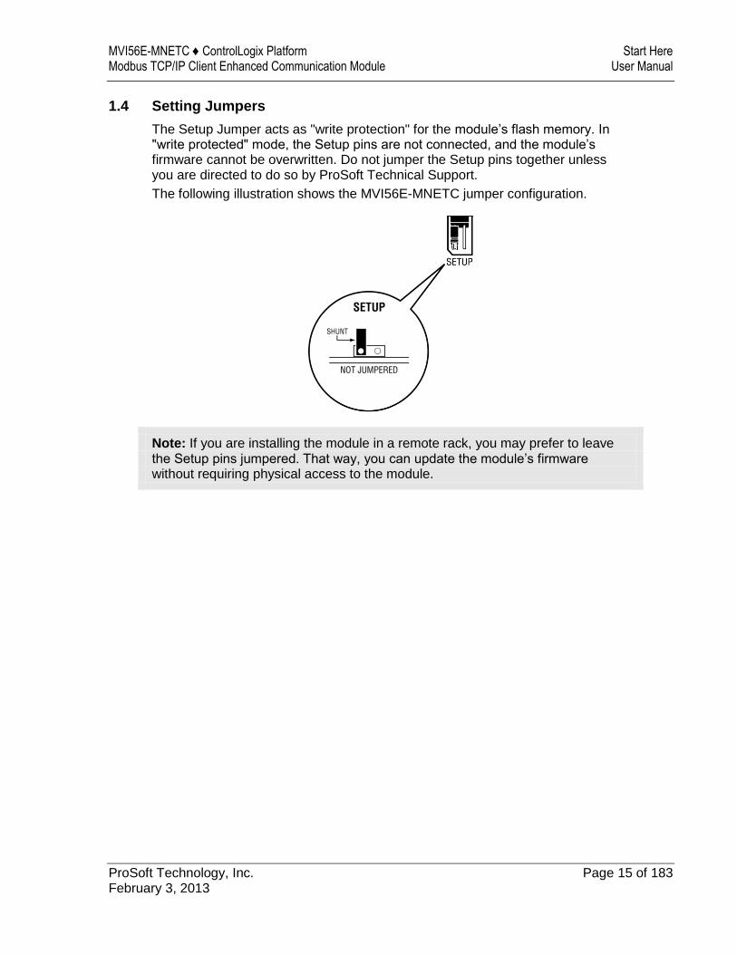
1.4 Setting Jumpers
The Setup Jumper acts as "write protection" for the module’s flash memory. In "write protected" mode, the Setup pins are not connected, and the module’s firmware cannot be overwritten. Do not jumper the Setup pins together unless you are directed to do so by ProSoft Technical Support.
The following illustration shows the MVI56E-MNETC jumper configuration.
Note: If you are installing the module in a remote rack, you may prefer to leave the Setup pins jumpered. That way, you can update the module’s firmware without requiring physical access to the module.
Guide to the MVI56E-MNETC User Manual MVI56E-MNETC ♦ ControlLogix Platform User Manual Modbus TCP/IP Client Enhanced Communication Module
Page 16 of 183 ProSoft Technology, Inc. February 3, 2013
1.5 Installing the Module in the Rack
If you have not already installed and configured your ControlLogix processor and power supply, please do so before installing the MVI56E-MNETC module. Refer to your Rockwell Automation product documentation for installation instructions.
Warning: You must follow all safety instructions when installing this or any other electronic devices. Failure to follow safety procedures could result in damage to hardware or data, or even serious injury or death to personnel. Refer to the documentation for each device you plan to connect to verify that suitable safety procedures are in place before installing or servicing the device.
After you have checked the placement of the jumpers, insert the MVI56E-MNETC into the ControlLogix chassis. Use the same technique recommended by Rockwell Automation to remove and install ControlLogix modules.
You can install or remove ControlLogix system components while chassis power is applied and the system is operating. However, please note the following warning.
Warning: When you insert or remove the module while backplane power is on, an electrical arc can occur. An electrical arc can cause personal injury or property damage by sending an erroneous signal to your system’s actuators. This can cause unintended machine motion or loss of process control. Electrical arcs may also cause an explosion when they happen in a hazardous environment. Verify that power is removed or the area is non-hazardous before proceeding. Repeated electrical arcing causes excessive wear to contacts on both the module and its mating connector. Worn contacts may create electrical resistance that can affect module operation.
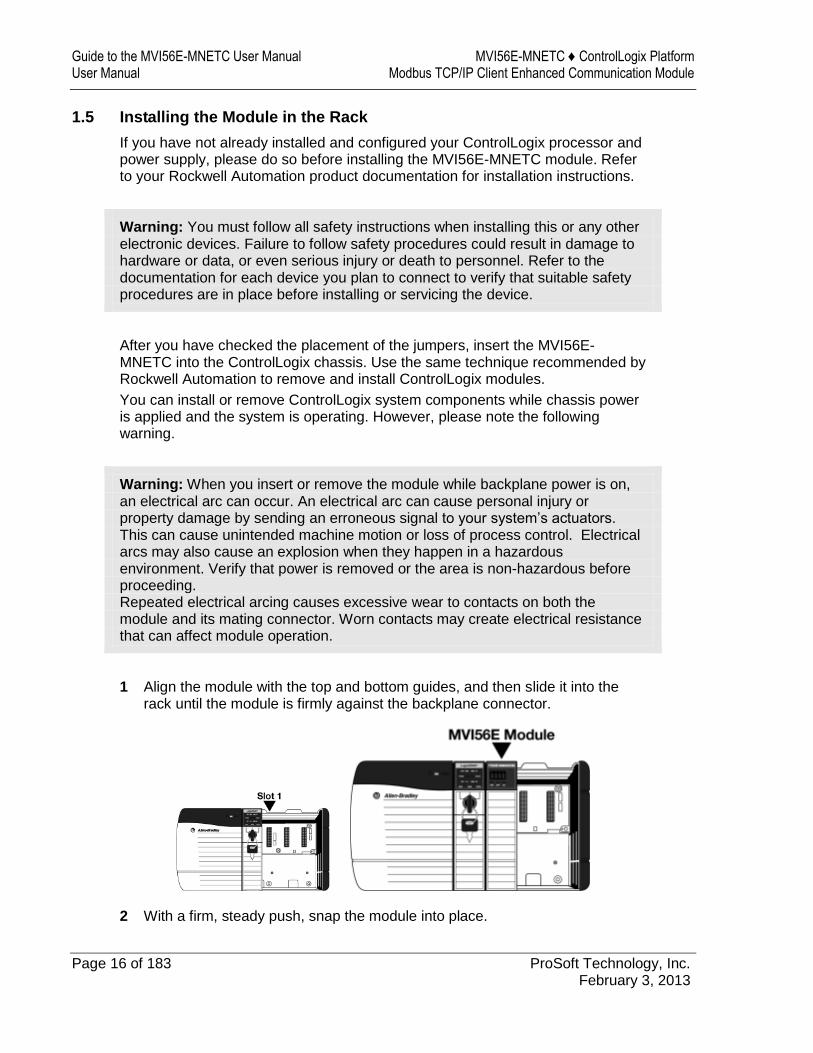
1 Align the module with the top and bottom guides, and then slide it into the rack until the module is firmly against the backplane connector.
2 With a firm, steady push, snap the module into place.
MVI56E-MNETC ♦ ControlLogix Platform Start Here Modbus TCP/IP Client Enhanced Communication Module User Manual
ProSoft Technology, Inc. Page 17 of 183 February 3, 2013
3 Check that the holding clips on the top and bottom of the module are securely in the locking holes of the rack.
4 Make a note of the slot location. You must identify the slot in which the module is installed in order for the sample program to work correctly. Slot numbers are identified on the green circuit board (backplane) of the ControlLogix rack.
5 Turn power ON.
Note: If you insert the module improperly, the system may stop working or may behave unpredictably.
Guide to the MVI56E-MNETC User Manual MVI56E-MNETC ♦ ControlLogix Platform User Manual Modbus TCP/IP Client Enhanced Communication Module
Page 18 of 183 ProSoft Technology, Inc. February 3, 2013
1.6 Importing the Sample Add-On Instruction
Note: This section only applies if your processor is using RSLogix 5000 version 16 or higher. If you have an earlier version, please see Using the Sample Program (page 172).
Before You Begin
Two Add-On Instructions are provided for the MVI56E-MNETC module. The first is required for setting up the module; the second is optional.
Copy the files from the ProSoft Solutions CD-ROM, or download them from www.prosoft-technology.com. Save them to a convenient location in your PC, such as Desktop or My Documents.
File Name Description
MVI56EMNETC_AddOn_Rung_v1_8.L5X L5X file containing Add-On Instruction, user defined data types, controller tags and ladder logic required to configure the MVI56E-MNETC module
MVI56EMNETC_Optional_AddOn_Rung_v1_0.L5X
Optional L5X file containing additional Add-On Instruction with logic for changing Ethernet configuration and clock settings.
MVI56E-MNETC ♦ ControlLogix Platform Start Here Modbus TCP/IP Client Enhanced Communication Module User Manual
ProSoft Technology, Inc. Page 19 of 183 February 3, 2013
1.7 Creating a New RSLogix 5000 Project
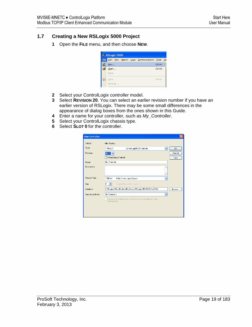
1 Open the FILE menu, and then choose NEW.
2 Select your ControlLogix controller model. 3 Select REVISION 20. You can select an earlier revision number if you have an
earlier version of RSLogix. There may be some small differences in the appearance of dialog boxes from the ones shown in this Guide.
4 Enter a name for your controller, such as My_Controller. 5 Select your ControlLogix chassis type. 6 Select SLOT 0 for the controller.
Guide to the MVI56E-MNETC User Manual MVI56E-MNETC ♦ ControlLogix Platform User Manual Modbus TCP/IP Client Enhanced Communication Module
Page 20 of 183 ProSoft Technology, Inc. February 3, 2013
1.7.1 Creating the Module
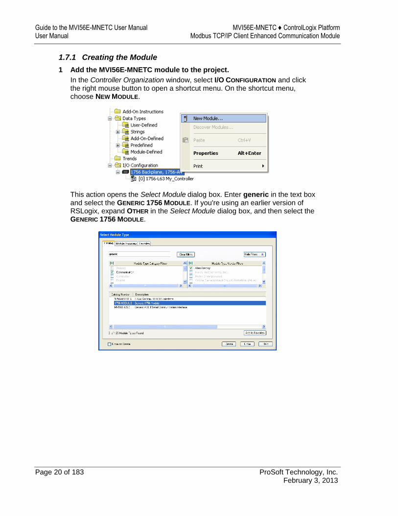
1 Add the MVI56E-MNETC module to the project.
In the Controller Organization window, select I/O CONFIGURATION and click the right mouse button to open a shortcut menu. On the shortcut menu, choose NEW MODULE.
This action opens the Select Module dialog box. Enter generic in the text box and select the GENERIC 1756 MODULE. If you're using an earlier version of RSLogix, expand OTHER in the Select Module dialog box, and then select the GENERIC 1756 MODULE.
MVI56E-MNETC ♦ ControlLogix Platform Start Here Modbus TCP/IP Client Enhanced Communication Module User Manual
ProSoft Technology, Inc. Page 21 of 183 February 3, 2013
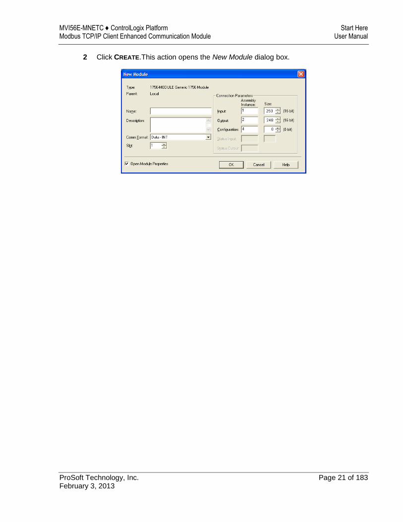
2 Click CREATE.This action opens the New Module dialog box.
Guide to the MVI56E-MNETC User Manual MVI56E-MNETC ♦ ControlLogix Platform User Manual Modbus TCP/IP Client Enhanced Communication Module
Page 22 of 183 ProSoft Technology, Inc. February 3, 2013
3 In the New Module dialog box, enter the following values.
Parameter Value
Name Enter a module identification string. Example: MNETC
Description Enter a description for the module. Example: MODBUS TCP/IP
CLIENT ENHANCED COMMUNICATION MODULE
Comm Format Select DATA-INT.
Slot Enter the slot number in the rack where the MVI56E-MNETC module is located.
Input Assembly Instance 1
Input Size 250
Output Assembly Instance 2
Output Size 248
Configuration Assembly Instance 4
Configuration Size 0
Important: You must select the Comm Format as DATA - INT in the dialog box; otherwise the module will not communicate over the backplane of the ControlLogix rack.
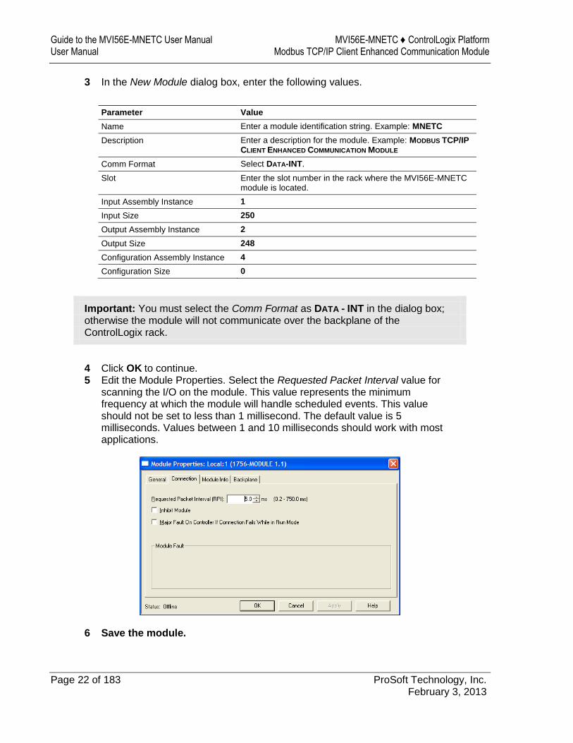
4 Click OK to continue. 5 Edit the Module Properties. Select the Requested Packet Interval value for
scanning the I/O on the module. This value represents the minimum frequency at which the module will handle scheduled events. This value should not be set to less than 1 millisecond. The default value is 5 milliseconds. Values between 1 and 10 milliseconds should work with most applications.
6 Save the module.
MVI56E-MNETC ♦ ControlLogix Platform Start Here Modbus TCP/IP Client Enhanced Communication Module User Manual
ProSoft Technology, Inc. Page 23 of 183 February 3, 2013
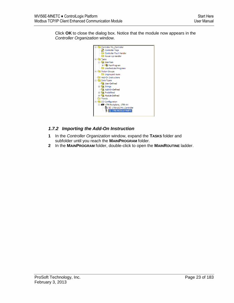
Click OK to close the dialog box. Notice that the module now appears in the Controller Organization window.
1.7.2 Importing the Add-On Instruction
1 In the Controller Organization window, expand the TASKS folder and subfolder until you reach the MAINPROGRAM folder.
2 In the MAINPROGRAM folder, double-click to open the MAINROUTINE ladder.
Guide to the MVI56E-MNETC User Manual MVI56E-MNETC ♦ ControlLogix Platform User Manual Modbus TCP/IP Client Enhanced Communication Module
Page 24 of 183 ProSoft Technology, Inc. February 3, 2013
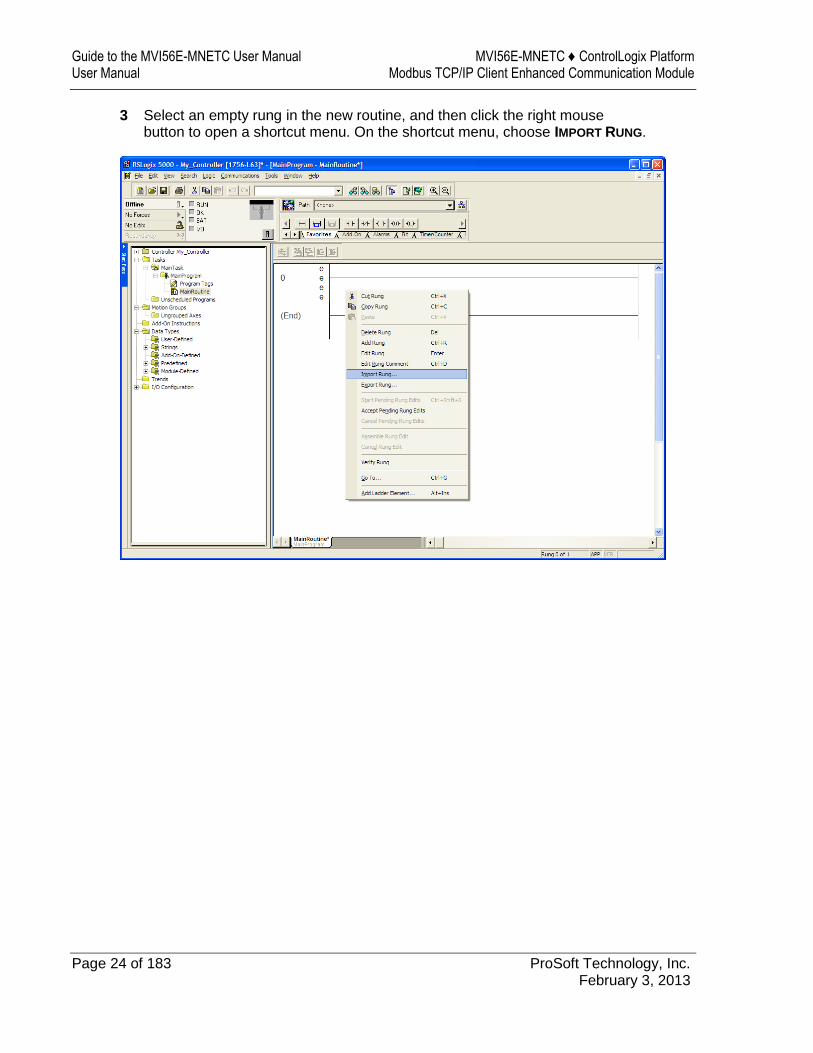
3 Select an empty rung in the new routine, and then click the right mouse button to open a shortcut menu. On the shortcut menu, choose IMPORT RUNG.
MVI56E-MNETC ♦ ControlLogix Platform Start Here Modbus TCP/IP Client Enhanced Communication Module User Manual
ProSoft Technology, Inc. Page 25 of 183 February 3, 2013
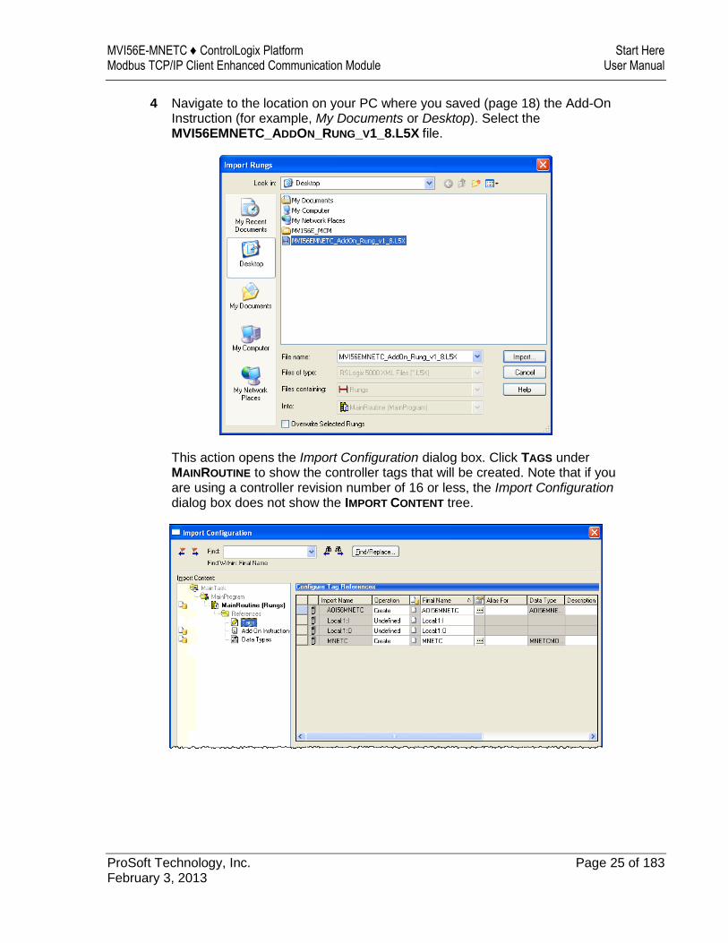
4 Navigate to the location on your PC where you saved (page 18) the Add-On Instruction (for example, My Documents or Desktop). Select the MVI56EMNETC_ADDON_RUNG_V1_8.L5X file.
This action opens the Import Configuration dialog box. Click TAGS under MAINROUTINE to show the controller tags that will be created. Note that if you are using a controller revision number of 16 or less, the Import Configuration dialog box does not show the IMPORT CONTENT tree.
Guide to the MVI56E-MNETC User Manual MVI56E-MNETC ♦ ControlLogix Platform User Manual Modbus TCP/IP Client Enhanced Communication Module
Page 26 of 183 ProSoft Technology, Inc. February 3, 2013
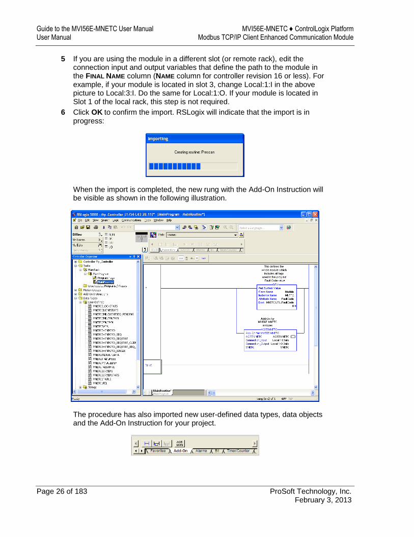
5 If you are using the module in a different slot (or remote rack), edit the connection input and output variables that define the path to the module in the FINAL NAME column (NAME column for controller revision 16 or less). For example, if your module is located in slot 3, change Local:1:I in the above picture to Local:3:I. Do the same for Local:1:O. If your module is located in Slot 1 of the local rack, this step is not required.
6 Click OK to confirm the import. RSLogix will indicate that the import is in progress:
When the import is completed, the new rung with the Add-On Instruction will be visible as shown in the following illustration.
The procedure has also imported new user-defined data types, data objects and the Add-On Instruction for your project.
MVI56E-MNETC ♦ ControlLogix Platform Start Here Modbus TCP/IP Client Enhanced Communication Module User Manual
ProSoft Technology, Inc. Page 27 of 183 February 3, 2013
7 Save the application and then download the sample ladder logic to the processor.
Adding Multiple Modules (Optional)
Important: If your application requires more than one MVI56-MNETC module in the same project, follow the steps below.
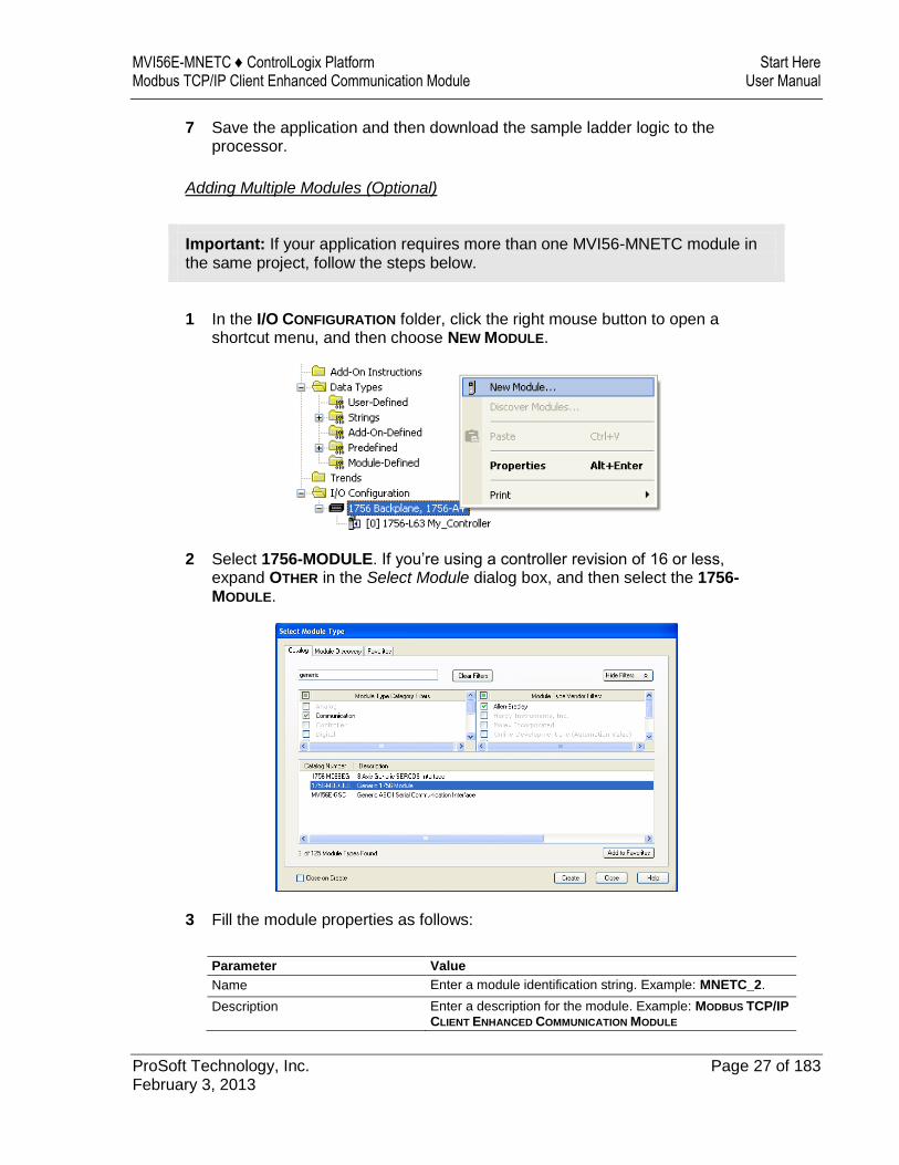
1 In the I/O CONFIGURATION folder, click the right mouse button to open a shortcut menu, and then choose NEW MODULE.
2 Select 1756-MODULE. If you’re using a controller revision of 16 or less, expand OTHER in the Select Module dialog box, and then select the 1756-MODULE.
3 Fill the module properties as follows:
Parameter Value
Name Enter a module identification string. Example: MNETC_2.
Description Enter a description for the module. Example: MODBUS TCP/IP
CLIENT ENHANCED COMMUNICATION MODULE
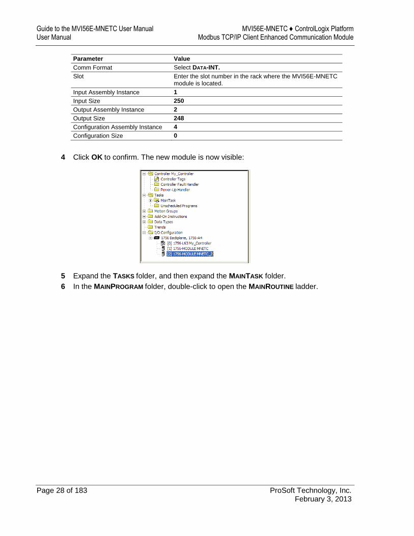
Guide to the MVI56E-MNETC User Manual MVI56E-MNETC ♦ ControlLogix Platform User Manual Modbus TCP/IP Client Enhanced Communication Module
Page 28 of 183 ProSoft Technology, Inc. February 3, 2013
Parameter Value
Comm Format Select DATA-INT.
Slot Enter the slot number in the rack where the MVI56E-MNETC module is located.
Input Assembly Instance 1
Input Size 250
Output Assembly Instance 2
Output Size 248
Configuration Assembly Instance 4
Configuration Size 0
4 Click OK to confirm. The new module is now visible:
5 Expand the TASKS folder, and then expand the MAINTASK folder.
6 In the MAINPROGRAM folder, double-click to open the MAINROUTINE ladder.
MVI56E-MNETC ♦ ControlLogix Platform Start Here Modbus TCP/IP Client Enhanced Communication Module User Manual
ProSoft Technology, Inc. Page 29 of 183 February 3, 2013
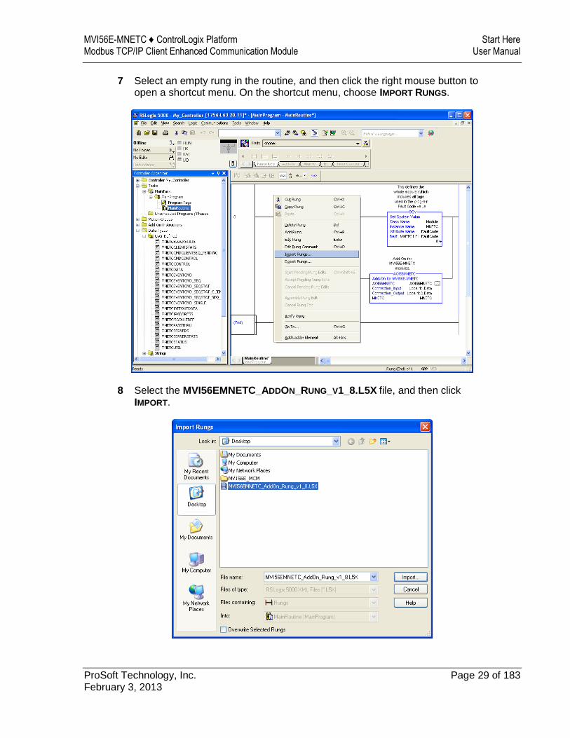
7 Select an empty rung in the routine, and then click the right mouse button to open a shortcut menu. On the shortcut menu, choose IMPORT RUNGS.
8 Select the MVI56EMNETC_ADDON_RUNG_V1_8.L5X file, and then click IMPORT.
Guide to the MVI56E-MNETC User Manual MVI56E-MNETC ♦ ControlLogix Platform User Manual Modbus TCP/IP Client Enhanced Communication Module
Page 30 of 183 ProSoft Technology, Inc. February 3, 2013
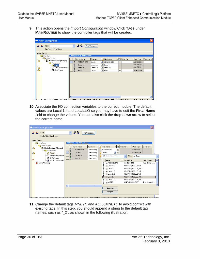
9 This action opens the Import Configuration window Click TAGS under MAINROUTINE to show the controller tags that will be created.
10 Associate the I/O connection variables to the correct module. The default values are Local:1:I and Local:1:O so you may have to edit the Final Name field to change the values. You can also click the drop-down arrow to select the correct name.
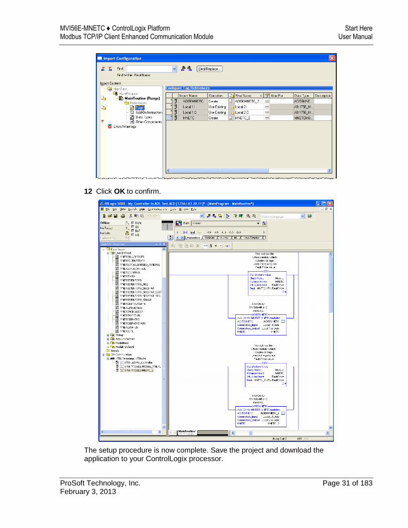
11 Change the default tags MNETC and AOI56MNETC to avoid conflict with existing tags. In this step, you should append a string to the default tag names, such as "_2", as shown in the following illustration.
MVI56E-MNETC ♦ ControlLogix Platform Start Here Modbus TCP/IP Client Enhanced Communication Module User Manual
ProSoft Technology, Inc. Page 31 of 183 February 3, 2013
12 Click OK to confirm.
The setup procedure is now complete. Save the project and download the application to your ControlLogix processor.
Guide to the MVI56E-MNETC User Manual MVI56E-MNETC ♦ ControlLogix Platform User Manual Modbus TCP/IP Client Enhanced Communication Module
Page 32 of 183 ProSoft Technology, Inc. February 3, 2013
Adjusting the Input and Output Array Sizes
Note: It is unnecessary to manually edit the ReadData and WriteData user-defined data types in the ladder logic, as these are automatically updated to match the changed array sizes from ProSoft Configuration Builder.
Tip: If you have not installed ProSoft Configuration Builder, see page 38 for the steps to install the software.
The module internal database is divided into two user-configurable areas:
Read Data Write Data
The Read Data area is moved from the module to the processor, while the Write Data area is moved from the processor to the module.
The MVI56E-MNETC Add-On Instruction rung is configured for 600 registers of Read Data and 600 registers of Write Data, which is sufficient for most applications. However, you can configure the sizes of these data areas to meet the needs of your application.
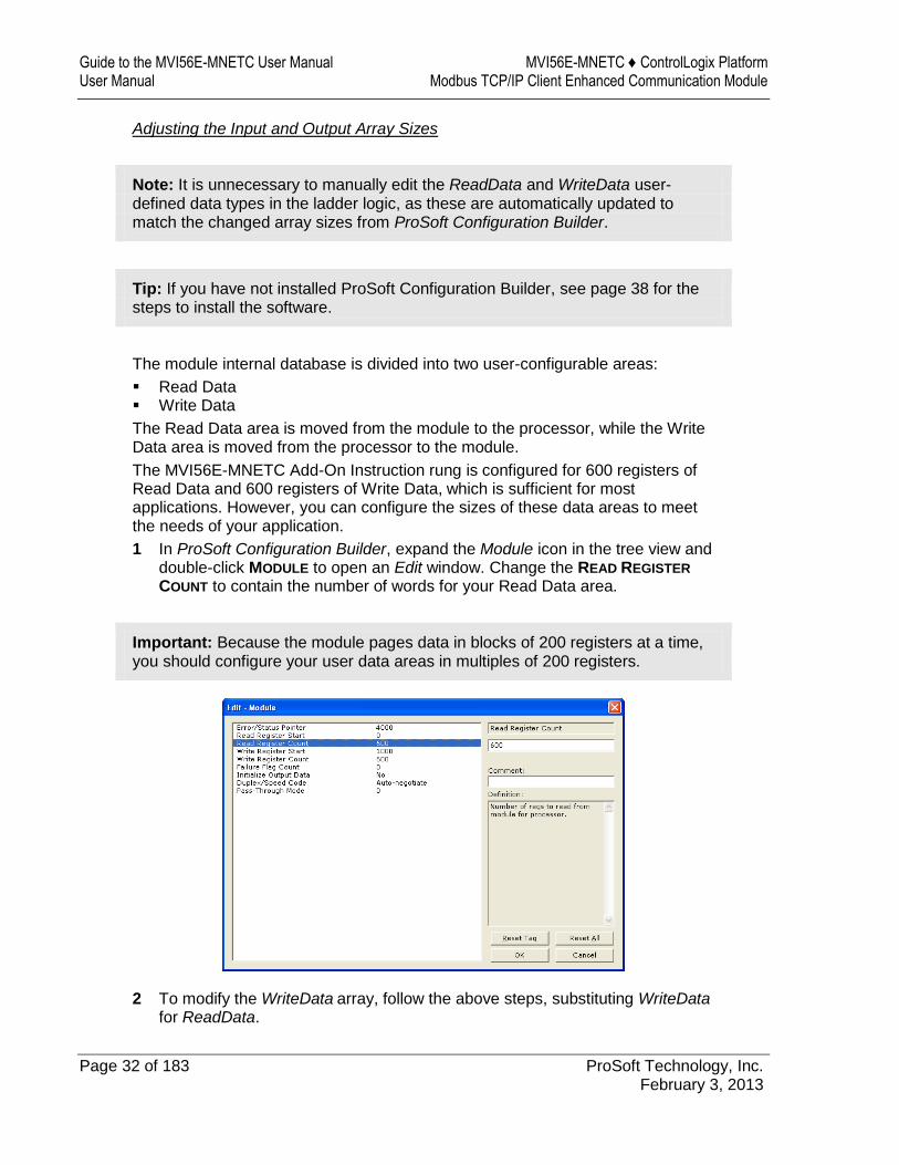
1 In ProSoft Configuration Builder, expand the Module icon in the tree view and double-click MODULE to open an Edit window. Change the READ REGISTER
COUNT to contain the number of words for your Read Data area.
Important: Because the module pages data in blocks of 200 registers at a time, you should configure your user data areas in multiples of 200 registers.
2 To modify the WriteData array, follow the above steps, substituting WriteData
for ReadData.

MVI56E-MNETC ♦ ControlLogix Platform Start Here Modbus TCP/IP Client Enhanced Communication Module User Manual
ProSoft Technology, Inc. Page 33 of 183 February 3, 2013
3 Save and download the configuration to the module (page 65) and reboot.
Make sure that the ReadData and WriteData arrays do not overlap in the module memory. For example, if your application requires 2000 words of WriteData starting at register 0, then your Read Register Start parameter must be set to a value of 2000 or greater.
Guide to the MVI56E-MNETC User Manual MVI56E-MNETC ♦ ControlLogix Platform User Manual Modbus TCP/IP Client Enhanced Communication Module
Page 34 of 183 ProSoft Technology, Inc. February 3, 2013
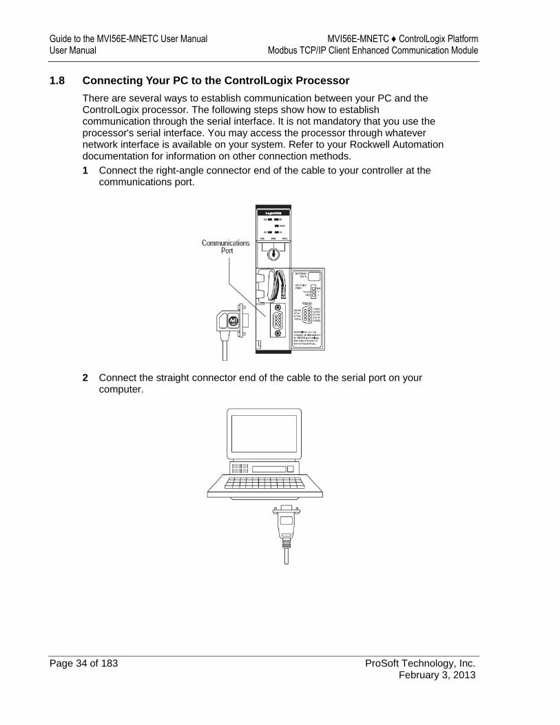
1.8 Connecting Your PC to the ControlLogix Processor
There are several ways to establish communication between your PC and the ControlLogix processor. The following steps show how to establish communication through the serial interface. It is not mandatory that you use the processor's serial interface. You may access the processor through whatever network interface is available on your system. Refer to your Rockwell Automation documentation for information on other connection methods.
1 Connect the right-angle connector end of the cable to your controller at the communications port.
2 Connect the straight connector end of the cable to the serial port on your computer.
MVI56E-MNETC ♦ ControlLogix Platform Start Here Modbus TCP/IP Client Enhanced Communication Module User Manual
ProSoft Technology, Inc. Page 35 of 183 February 3, 2013
1.9 Downloading the Sample Program to the Processor
Note: The key switch on the front of the ControlLogix processor must be in the REM or PROG position.
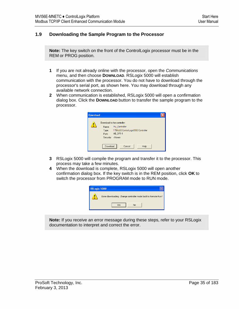
1 If you are not already online with the processor, open the Communications
menu, and then choose DOWNLOAD. RSLogix 5000 will establish communication with the processor. You do not have to download through the processor's serial port, as shown here. You may download through any available network connection.
2 When communication is established, RSLogix 5000 will open a confirmation dialog box. Click the DOWNLOAD button to transfer the sample program to the processor.
3 RSLogix 5000 will compile the program and transfer it to the processor. This process may take a few minutes.
4 When the download is complete, RSLogix 5000 will open another confirmation dialog box. If the key switch is in the REM position, click OK to switch the processor from PROGRAM mode to RUN mode.
Note: If you receive an error message during these steps, refer to your RSLogix documentation to interpret and correct the error.

Guide to the MVI56E-MNETC User Manual MVI56E-MNETC ♦ ControlLogix Platform User Manual Modbus TCP/IP Client Enhanced Communication Module
Page 36 of 183 ProSoft Technology, Inc. February 3, 2013
MVI56E-MNETC ♦ ControlLogix Platform Configuring the MVI56E-MNETC Module Modbus TCP/IP Client Enhanced Communication Module User Manual
ProSoft Technology, Inc. Page 37 of 183 February 3, 2013
2 Configuring the MVI56E-MNETC Module
In This Chapter
Installing ProSoft Configuration Builder ................................................. 38
Using ProSoft Configuration Builder Software ....................................... 39
Connecting Your PC to the Module ....................................................... 61
Downloading the Project to the Module ................................................. 65
Guide to the MVI56E-MNETC User Manual MVI56E-MNETC ♦ ControlLogix Platform User Manual Modbus TCP/IP Client Enhanced Communication Module
Page 38 of 183 ProSoft Technology, Inc. February 3, 2013
2.1 Installing ProSoft Configuration Builder
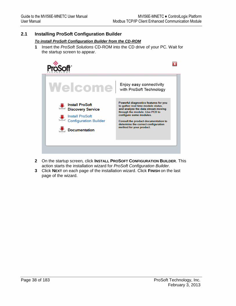
To install ProSoft Configuration Builder from the CD-ROM
1 Insert the ProSoft Solutions CD-ROM into the CD drive of your PC. Wait for the startup screen to appear.
2 On the startup screen, click INSTALL PROSOFT CONFIGURATION BUILDER. This action starts the installation wizard for ProSoft Configuration Builder.
3 Click NEXT on each page of the installation wizard. Click FINISH on the last page of the wizard.
MVI56E-MNETC ♦ ControlLogix Platform Configuring the MVI56E-MNETC Module Modbus TCP/IP Client Enhanced Communication Module User Manual
ProSoft Technology, Inc. Page 39 of 183 February 3, 2013
2.2 Using ProSoft Configuration Builder Software
ProSoft Configuration Builder (PCB) provides a convenient way to manage module configuration files customized to meet your application needs. PCB is not only a powerful solution for new configuration files, but also allows you to import information from previously installed (known working) configurations to new projects.
Note: During startup and initialization, the MVI56E-MNETC module receives its protocol and backplane configuration information from the installed Personality Module (Compact Flash). Use ProSoft Configuration Builder to configure module settings and to download changes to the Personality Module.
2.2.1 Upgrading from MVI56-MNETC in ProSoft Configuration Builder
MVI56E-MNETC modules are fully backward-compatible with MVI56-MNETC modules. However, you will need to convert your MVI56-MNETC configuration in ProSoft Configuration Builder to a form that your new MVI56E-MNETC module will accept when you download it.
ProSoft Configuration Builder version 2.2.2 or later has an upgrade option that easily performs this conversion, while preserving all your configuration settings and any name you may have given your module.
Important: For this procedure, you need to have ProSoft Configuration Builder version 2.2.2 or later installed on your PC. You can download the latest version from www.prosoft-technology.com.
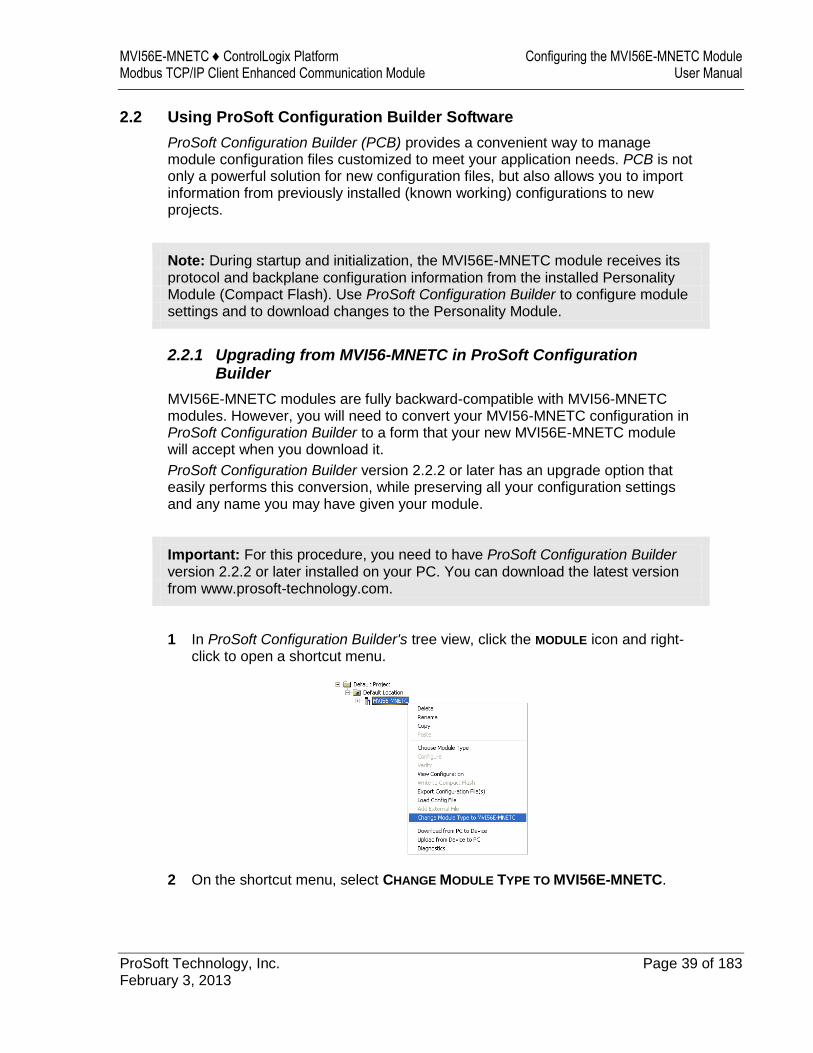
1 In ProSoft Configuration Builder's tree view, click the MODULE icon and right-click to open a shortcut menu.
2 On the shortcut menu, select CHANGE MODULE TYPE TO MVI56E-MNETC.
Guide to the MVI56E-MNETC User Manual MVI56E-MNETC ♦ ControlLogix Platform User Manual Modbus TCP/IP Client Enhanced Communication Module
Page 40 of 183 ProSoft Technology, Inc. February 3, 2013
2.2.2 Setting Up the Project
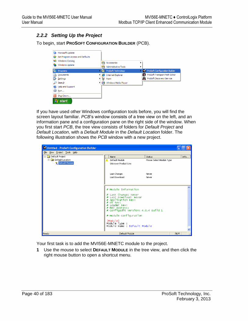
To begin, start PROSOFT CONFIGURATION BUILDER (PCB).
If you have used other Windows configuration tools before, you will find the screen layout familiar. PCB’s window consists of a tree view on the left, and an information pane and a configuration pane on the right side of the window. When you first start PCB, the tree view consists of folders for Default Project and Default Location, with a Default Module in the Default Location folder. The following illustration shows the PCB window with a new project.
Your first task is to add the MVI56E-MNETC module to the project.
1 Use the mouse to select DEFAULT MODULE in the tree view, and then click the right mouse button to open a shortcut menu.
MVI56E-MNETC ♦ ControlLogix Platform Configuring the MVI56E-MNETC Module Modbus TCP/IP Client Enhanced Communication Module User Manual
ProSoft Technology, Inc. Page 41 of 183 February 3, 2013
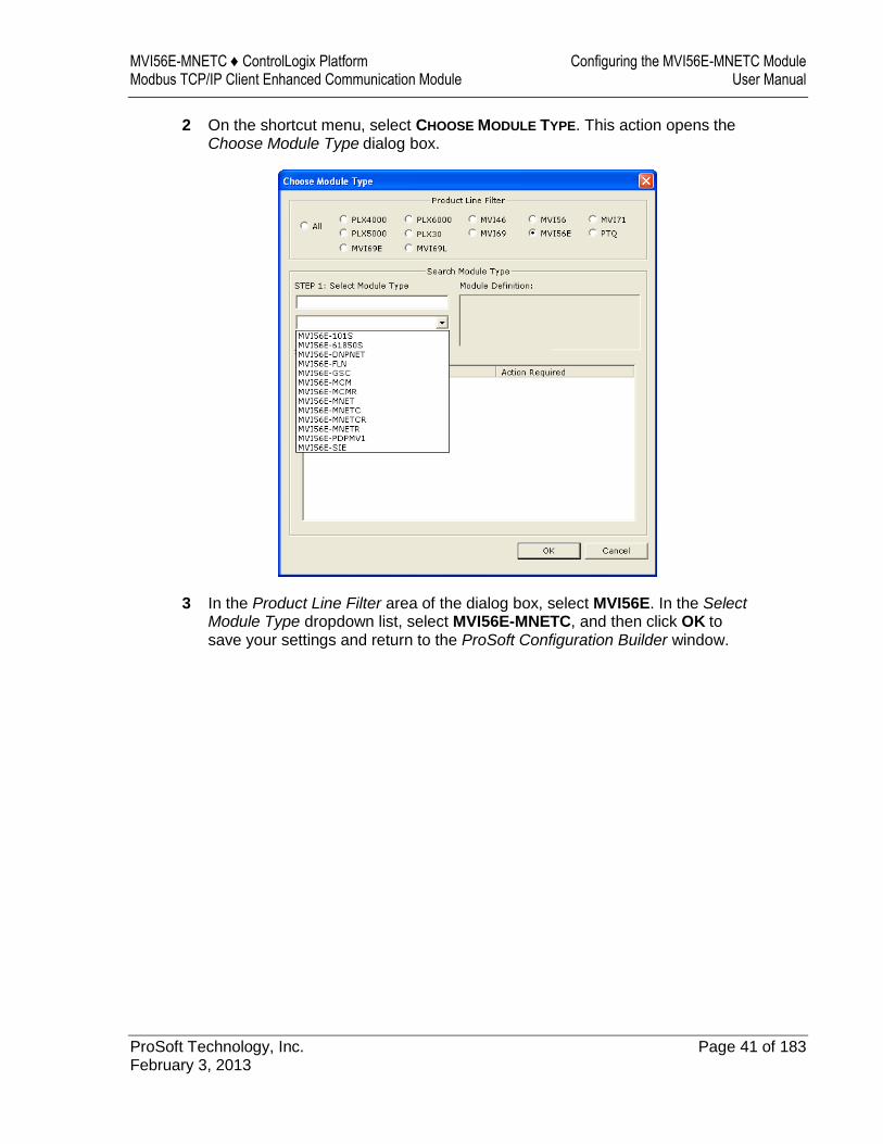
2 On the shortcut menu, select CHOOSE MODULE TYPE. This action opens the
Choose Module Type dialog box.
3 In the Product Line Filter area of the dialog box, select MVI56E. In the Select Module Type dropdown list, select MVI56E-MNETC, and then click OK to save your settings and return to the ProSoft Configuration Builder window.
Guide to the MVI56E-MNETC User Manual MVI56E-MNETC ♦ ControlLogix Platform User Manual Modbus TCP/IP Client Enhanced Communication Module
Page 42 of 183 ProSoft Technology, Inc. February 3, 2013
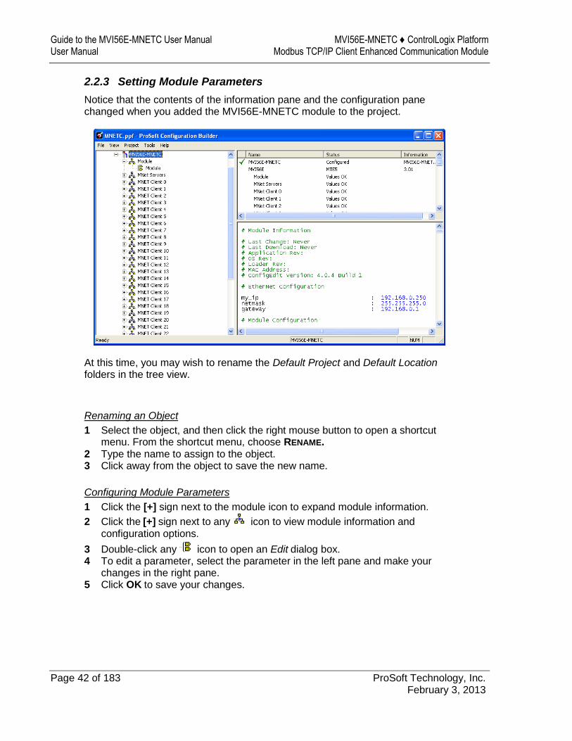
2.2.3 Setting Module Parameters
Notice that the contents of the information pane and the configuration pane changed when you added the MVI56E-MNETC module to the project.
At this time, you may wish to rename the Default Project and Default Location folders in the tree view.
Renaming an Object
1 Select the object, and then click the right mouse button to open a shortcut menu. From the shortcut menu, choose RENAME.
2 Type the name to assign to the object. 3 Click away from the object to save the new name.
Configuring Module Parameters
1 Click the [+] sign next to the module icon to expand module information.
2 Click the [+] sign next to any icon to view module information and configuration options.
3 Double-click any icon to open an Edit dialog box. 4 To edit a parameter, select the parameter in the left pane and make your
changes in the right pane. 5 Click OK to save your changes.
MVI56E-MNETC ♦ ControlLogix Platform Configuring the MVI56E-MNETC Module Modbus TCP/IP Client Enhanced Communication Module User Manual
ProSoft Technology, Inc. Page 43 of 183 February 3, 2013
Printing a Configuration File
1 Select the module icon, and then click the right mouse button to open a shortcut menu.
2 On the shortcut menu, choose VIEW CONFIGURATION. This action opens the View Configuration window.
3 In the View Configuration window, open the FILE menu, and choose PRINT. This action opens the Print dialog box.
4 In the Print dialog box, choose the printer to use from the drop-down list, select printing options, and then click OK.
2.2.4 Module
This section of the configuration describes the database setup and module-level parameters.
Backplane Error/Status Pointer
1 to 9955
This parameter sets the address in the internal database where the backplane error/status data will be placed. If you want the error/status data to be moved to the processor and placed into the ReadData array, the value entered should be a module memory address in the Read Data area. If the value is set to -1, the error/status data will not be stored in the module's internal database and will not be transferred to the processor's ReadData array.
Enabling the Error/Status Pointer is optional. The error/status data is routinely returned as part of the input image, which is continually being transferred from the module to the processor. For more information, see Normal Data Transfer Blocks (page 114).
Read Register Start
0 to 9999
The Read Register Start parameter specifies the start of the Read Data area in module memory. Data in this area will be transferred from the module to the processor.
Note: Total user database memory space is limited to the first 10,000 registers of module memory, addresses 0 through 9999. Therefore, the practical limit for this parameter is 9999 minus the value entered for Read Register Count, so that the Read Data Area does not try to extend above address 9999. Read Data and Write Data Areas must be configured to occupy separate address ranges in module memory and should not be allowed to overlap.
Note: To use the extended database registers, your MVI56E-MNETC module needs to have firmware version 3.01 or higher, and your MVI56E-MNETC Add-On Instruction needs to be version 1.8 or higher. Earlier versions support up to 5000 database registers.
Guide to the MVI56E-MNETC User Manual MVI56E-MNETC ♦ ControlLogix Platform User Manual Modbus TCP/IP Client Enhanced Communication Module
Page 44 of 183 ProSoft Technology, Inc. February 3, 2013
Read Register Count
0 to 10,000
The Read Register Count parameter specifies the size of the Read Data area of module memory and the number of registers to transfer from this area to the processor, up to a maximum of 10,000 words.
Note: Total Read Register Count and Write Register Count cannot exceed 10,000 total registers. Read Data and Write Data Areas must be configured to occupy separate address ranges in module memory and should not be allowed to overlap.
Write Register Start
0 to 9999
The Write Register Start parameter specifies the start of the Write Data area in module memory. Data in this area will be transferred in from the processor.
Note: Total user database memory space is limited to the first 10,000 registers of module memory, addresses 0 through 9999. Therefore, the practical limit for this parameter is 9999 minus the value entered for Write Register Count, so that the Write Data Area does not try to extend above address 9999. Read Data and Write Data Areas must be configured to occupy separate address ranges in module memory and should not be allowed to overlap.
Write Register Count
0 to 10,000
The Write Register Count parameter specifies the size of the Write Data area of module memory and the number of registers to transfer from the processor to this memory area, up to a maximum value of 5000 words.
Note: Total Read Register Count and Write Register Count cannot exceed 10,000 total registers. Read Data and Write Data Areas must be configured to occupy separate address ranges in module memory and should not be allowed to overlap.
MVI56E-MNETC ♦ ControlLogix Platform Configuring the MVI56E-MNETC Module Modbus TCP/IP Client Enhanced Communication Module User Manual
ProSoft Technology, Inc. Page 45 of 183 February 3, 2013
Failure Flag Count
If this value is greater than zero the protocol communication will be interrupted once a backplane failure is detected, or communication with the processor fails. A value of zero will disable this feature.
Initialize Output Data
0 = No, 1 = Yes This par ameter is used to determi ne if the output data for the module should be i nitialized with values from the processor. If the val ue is set to 0, the output data will be i nitialized to 0. If the value is set to 1, the data will be initi alized with data fr om the pr ocessor. Use of this opti on requires associated ladder l ogic to pass the data from the proces sor to the modul e.
Pass-Through Mode
0, 1, 2 or 3
This parameter specifies the pass-through mode for write messages received by the MNET and MBAP server ports.
If the parameter is set to 0, all write messages will be placed in the module’s virtual database.
If a value of 1 is entered, write messages received will be sent to the processor as unformatted messages.
If a value of 2 is entered, write messages received will be sent to the processor as formatted messages.
If a value of 3 is entered, write messages received will be sent to the processor with the bytes swapped in a formatted message.
Note: To use pass-through mode, your MVI56E-MNETC module needs to have firmware version 3.01 or higher, and your MVI56E-MNETC Add-On Instruction needs to be version 1.8 or higher. Earlier versions do not support pass-through mode.
Duplex/Speed Code
0, 1, 2, 3 or 4
This parameter allows you to cause the module to use a specific duplex and speed setting.
Value = 1: Half duplex, 10 MB speed Value = 2: Full duplex, 10 MB speed Value = 3: Half duplex, 100 MB speed Value = 4: Full duplex, 100 MB speed Value = 0: Auto-negotiate
Auto-negotiate is the default value for backward compatibility. This feature is not implemented in older software revisions.
Guide to the MVI56E-MNETC User Manual MVI56E-MNETC ♦ ControlLogix Platform User Manual Modbus TCP/IP Client Enhanced Communication Module
Page 46 of 183 ProSoft Technology, Inc. February 3, 2013
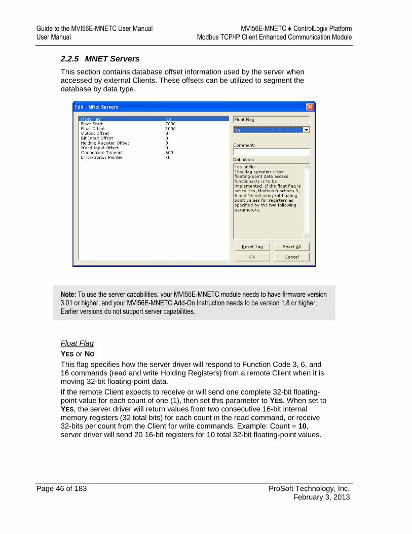
2.2.5 MNET Servers
This section contains database offset information used by the server when accessed by external Clients. These offsets can be utilized to segment the database by data type.
Note: To use the server capabilities, your MVI56E-MNETC module needs to have firmware version 3.01 or higher, and your MVI56E-MNETC Add-On Instruction needs to be version 1.8 or higher. Earlier versions do not support server capabilities.
Float Flag
YES or NO
This flag specifies how the server driver will respond to Function Code 3, 6, and 16 commands (read and write Holding Registers) from a remote Client when it is moving 32-bit floating-point data.
If the remote Client expects to receive or will send one complete 32-bit floating-point value for each count of one (1), then set this parameter to YES. When set to YES, the server driver will return values from two consecutive 16-bit internal memory registers (32 total bits) for each count in the read command, or receive 32-bits per count from the Client for write commands. Example: Count = 10, server driver will send 20 16-bit registers for 10 total 32-bit floating-point values.
MVI56E-MNETC ♦ ControlLogix Platform Configuring the MVI56E-MNETC Module Modbus TCP/IP Client Enhanced Communication Module User Manual
ProSoft Technology, Inc. Page 47 of 183 February 3, 2013
If, however, the remote Client sends a count of two (2) for each 32-bit floating-point value it expects to receive or send, or, if you do not plan to use floating-point data in your application, then set this parameter to NO, which is the default setting.
You will also need to set the Float Start and Float Offset parameters to appropriate values whenever the Float Flag parameter is set to YES.
Float Start
0 TO 65535
Whenever the Float Flag parameter is set to YES, this parameter determines the lowest Modbus Address, received in commands from a remote Client, to consider as requests to read or write floating-point data. All commands with address values greater than or equal to this value will be considered floating-point data requests. All commands with address values less than this value will be considered normal 16-bit register data requests.
This parameter is used only if the Float Flag is set to YES. For example, if a value of 7000 is entered, all commands received with addresses of 47001 (or 407001) and above will be considered as requests for floating-point data and 32-bits of data will be returned for each count of one in the command.
You will also need to set the Float Offset parameter to an appropriate value whenever the Float Flag parameter is set to YES.
Float Offset
0 to 9999
This parameter defines the start register for floating-point data in the internal database. This parameter is used only if the Float Flag is enabled. For example, if the Float Offset value is set to 3000 and the Float Start parameter is set to 7000, data requests for register 7000 will use the internal Modbus register 3000.
Output Offset
0 to 9999
This parameter defines the start register for the Modbus command data in the internal database. This parameter is enabled when a value greater than 0 is set. For example, if the Output Offset value is set to 3000, data requests for Modbus Coil Register address 00001 will use the internal database register 3000, bit 0. If the Output Offset value is set to 3000, data requests for Modbus Coil register address 00016 will use the internal database register 3000, bit 15. Function codes affected are 1, 5, and 15.
Guide to the MVI56E-MNETC User Manual MVI56E-MNETC ♦ ControlLogix Platform User Manual Modbus TCP/IP Client Enhanced Communication Module
Page 48 of 183 ProSoft Technology, Inc. February 3, 2013
Bit Input Offset
0 to 9999
This parameter defines the start register for Modbus command data in the internal database. This parameter is enabled when a value greater than 0 is set. For example, if the Bit Input Offset value is set to 3000, data requests for Modbus Input Register address 10001 will use the internal database register 3000, bit 0. If the Bit Input Offset is set to 3000, data requests for Modbus Coil register address 10016 will use the internal database register 3000, bit 15. Function code 2 is affected.
Holding Register Offset
0 to 9999
This parameter defines the start register for the Modbus Command data in the internal database. This parameter is enabled when a value greater than 0 is set. For example, if the Holding Register Offset value is set to 4000, data requests for Modbus Word register 40001 will use the internal database register 4000. Function codes affected are 3, 6, 16, & 23.
Word Input Offset
0 to 9999
This parameter defines the start register for Modbus Command data in the internal database. This parameter is enabled when a value greater than 0 is set. For example, if the Word Input Offset value is set to 4000, data requests for Modbus Word register address 30001 will use the internal database register 4000. Function code 4 is affected.
Connection Timeout
0 to 1200 seconds
This is the number of seconds the server will wait to receive new data. If the server does not receive any new data during this time, it will close the connection.
2.2.6 MNET Client x
This section defines general configuration for the MNET Client (Master).
MVI56E-MNETC ♦ ControlLogix Platform Configuring the MVI56E-MNETC Module Modbus TCP/IP Client Enhanced Communication Module User Manual
ProSoft Technology, Inc. Page 49 of 183 February 3, 2013
Client Error/Status Pointer
-1 to 9990
This parameter sets the address in the internal database where the Client error/status data will be placed. If you want the error/status data to be moved to the processor and placed into the ReadData array, the value entered should be a module memory address in the Read Data area. If the value is set to -1, the error/status data will not be stored in the module's internal database and will not be transferred to the processor's ReadData array.
Enabling the Error/Status Pointer is optional. Alternatively, the error/status data for a specific Client can be requested by the processor and returned in a special Client Status block. For more information, see Client Status Blocks (page 122).
Command Error Pointer
-1 to 9984
This parameter sets the address in the internal database where the Command Error List data will be placed. If you want the Command Error List data to be moved to the processor and placed into the ReadData array, the value entered should be a module memory address in the Read Data area. If the value is set to -1, the Command Error List data will not be stored in the module's internal database and will not be transferred to the processor's ReadData array.
Enabling the Command Error Pointer is optional. Alternatively, the Command Error List data for a specific Client can be requested by the processor and returned in a special Client Status block. For more information, see Client Status Blocks (page 122).
Minimum Command Delay
0 to 65535 milliseconds
This parameter specifies the number of milliseconds to wait between the initial issuances of a command. This parameter can be used to delay all commands sent to servers to avoid "flooding" commands on the network. This parameter does not affect retries of a command as they will be issued when failure is recognized.
Response Timeout
0 to 65535 milliseconds
This is the time in milliseconds that a Client will wait before re-transmitting a command if no response is received from the addressed server. The value to use depends on the type of communication network used, and the expected response time of the slowest device on the network.
Retry Count
0 to 10
This parameter specifies the number of times a command will be retried if it fails.
Guide to the MVI56E-MNETC User Manual MVI56E-MNETC ♦ ControlLogix Platform User Manual Modbus TCP/IP Client Enhanced Communication Module
Page 50 of 183 ProSoft Technology, Inc. February 3, 2013
Float Flag
YES or NO
This flag specifies how the Client driver will issue Function Code 3, 6, and 16 commands (read and write Holding Registers) to a remote server when it is moving 32-bit floating-point data.
If the remote server expects to receive or will send one complete 32-bit floating-point value for each count of one (1), then set this parameter to YES. When set to YES, the Client driver will send values from two consecutive 16-bit internal memory registers (32 total bits) for each count in a write command, or receive 32 bits per count from the server for read commands. Example: Count = 10, Client driver will send 20 16-bit registers for 10 total 32-bit floating-point values.
If, however, the remote server expects to use a count of two (2) for each 32-bit floating-point value it sends or receives, or if you do not plan to use floating-point data in your application, then set this parameter to NO, which is the default setting.
You will also need to set the Float Start and Float Offset parameters to appropriate values whenever the Float Flag parameter is set to YES.
Float Start
0 to 65535
Whenever the Float Flag parameter is set to YES, this parameter determines the lowest Modbus Address, used in commands to a remote server, to consider as commands to read or write floating-point data. All commands with address values greater than or equal to this value will be considered floating-point data commands. All commands with address values less than this value will be considered normal 16-bit register data commands.
This parameter is used only if the Float Flag is set to YES. For example, if a value of 7000 is entered, all commands sent with addresses of 47001 (or 407001) and above will be considered as floating-point data commands and 32 bits of data will be sent or received for each count of one in the command.
You will also need to set the Float Offset parameter to an appropriate value whenever the Float Flag parameter is set to YES.
Float Offset
0 to 9999
This parameter defines the start register for floating-point data in the internal database. This parameter is used only if the Float Flag is enabled. For example, if the Float Offset value is set to 3000 and the Float Start parameter is set to 7000, data requests for register 7000 will use the internal Modbus register 3000.
ARP Timeout
1 to 60
This parameter specifies the number of seconds to wait for an ARP reply after a request is issued.

MVI56E-MNETC ♦ ControlLogix Platform Configuring the MVI56E-MNETC Module Modbus TCP/IP Client Enhanced Communication Module User Manual
ProSoft Technology, Inc. Page 51 of 183 February 3, 2013
Command Error Delay
0 to 300
This parameter specifies the number of 100 millisecond intervals to turn off a command in the error list after an error is recognized for the command. If this parameter is set to 0, there will be no delay.
MBAP Port Override
YES or NO
If this parameter is set to YES, all messages generated by the Client driver will be MBAP format messages to all Service Port values.
If this parameter is set to NO (default value), or is omitted from the configuration file, all messages sent to Service Port 502 will be MBAP format messages, and all other Service Ports values will use the encapsulated Modbus message format (MNET).
Each Client is configured independently in the configuration file.
This parameter applies to firmware version 1.05 and above. For downward compatibility, you may omit this parameter from the Client's configuration.
2.2.7 MNET Client x Commands
The MNET Client x Commands section of the configuration sets the Modbus TCP/IP Client command list. This command list polls Modbus TCP/IP server devices attached to the Modbus TCP/IP Client port. The module supports numerous commands. This permits the module to interface with a wide variety of Modbus TCP/IP protocol devices.
The function codes used for each command are those specified in the Modbus protocol. Each command list record has the same format. The first part of the record contains the information relating to the MVI56E-MNETC communication module, and the second part contains information required to interface to the Modbus TCP/IP server device.
Guide to the MVI56E-MNETC User Manual MVI56E-MNETC ♦ ControlLogix Platform User Manual Modbus TCP/IP Client Enhanced Communication Module
Page 52 of 183 ProSoft Technology, Inc. February 3, 2013
Command List Overview
In order to interface the module with Modbus TCP/IP server devices, you must construct a command list. The commands in the list specify the server device to be addressed, the function to be performed (read or write), the data area in the device to interface with, and the registers in the internal database to be associated with the device data. The Client command list supports up to 16 commands.
The command list is processed from top (command #1) to bottom. A poll interval parameter is associated with each command to specify a minimum delay time in tenths of a second between the issuances of a command. If the user specifies a value of 10 for the parameter, the command will be executed no more frequently than every 1 second.
NOTE: If you are using only Event Commands or issuing commands from the Command List using Command Control from ladder logic, it is likely that the module will not leave any inactive TCP/IP socket connections open for more than 60-seconds. To maintain an open socket connection, your configuration or application must be designed so that at least one command is issued to each server connection at less than 60-second intervals. The 60-second connection timeout is not user-configurable and was put in place to prevent long delays between commands.
Commands Supported by the Module
The format of each command in the list depends on the Modbus Function Code being executed.
The following table lists the functions supported by the module.
Function Code Definition Supported in Client Supported in Server
1 Read Coil Status X X
2 Read Input Status X X
3 Read Holding Registers X X
4 Read Input Registers X X
5 Force (Write) Single Coil X X
6 Preset (Write) Single Register X X
7 Read Exception Status X X
8 Diagnostics X
15 Force (Write) Multiple Coils X X
16 Preset (Write) Multiple Registers
X X
22 Mask Write 4X X
23 Read/Write X
Each command list record has the same general format. The first part of the record contains the information relating to the communication module and the second part contains information required to interface to the Modbus TCP/IP server device.
MVI56E-MNETC ♦ ControlLogix Platform Configuring the MVI56E-MNETC Module Modbus TCP/IP Client Enhanced Communication Module User Manual
ProSoft Technology, Inc. Page 53 of 183 February 3, 2013
Command Entry Formats
The following table shows the structure of the configuration data necessary for each of the supported commands.
1 2 3 4 5 6 7 8 9 10
Enable Code
Internal Address
Poll Interval Time
Count Swap Code
IP Address
Serv Port
Slave Node
Function Code Device Modbus Address
Code Register (bit)
1/10th Seconds
Bit Count
0 IP Address
Port #
Address Read Coil (0x) Register
Code Register (bit)
1/10th Seconds
Bit Count
0 IP Address
Port #
Address Read Input (1x) Register
Code Register 1/10th Seconds
Word Count
Code IP Address
Port #
Address Read Holding Registers (4x)
Register
Code Register 1/10th Seconds
Word Count
0 IP Address
Port #
Address Read Input Registers (3x)
Register
Code 1 bit 1/10th Seconds
Bit Count
0 IP Address
Port #
Address Force (Write) Single Coil (0x)
Register
Code 1 bit 1/10th Seconds
Word Count
0 IP Address
Port #
Address Preset (Write) Single Register (4x)
Register
Code Register (bit)
1/10th Seconds
Bit Count
0 IP Address
Port #
Address Force (Write) Multiple Coil (0x)
Register
Code Register 1/10th Seconds
Word Count
0 IP Address
Port #
Address Preset (Write) Multiple Register (4x)
Register
The first part of the record is the module information, which relates to the MVI56E module, and the second part contains information required to interface to the server device.
Guide to the MVI56E-MNETC User Manual MVI56E-MNETC ♦ ControlLogix Platform User Manual Modbus TCP/IP Client Enhanced Communication Module
Page 54 of 183 ProSoft Technology, Inc. February 3, 2013
Command list example:
Enable
NO (0) or YES (1)
This field defines whether or not the command is to be executed.
Value Description
NO (0) The command is disabled and will not be executed in the normal polling sequence.
YES (1) The command is executed each scan of the command list if the Poll Interval Time is set to zero (0). If the Poll Interval time is set, the command will be executed when the interval timer expires.
CONDITIONAL (2) For function codes 5, 15, 6, or 16; data will be sent to the target device only when the data to be written has been changed. This applies only to write commands.
Important: The commands must also be enabled in the ladder logic in order for them to be executed. The MNETC.CONTROL.CmdControl.WriteCmdBits[x] controller tag array holds 16-command bit arrays for each Client. If a bit for a specific command is set to zero (0) in the WriteCmdBits[x] controller tag, the command will not be executed, regardless of its enabled or disabled state in the configuration. For more information, see Command Control Blocks (page 129).
MVI56E-MNETC ♦ ControlLogix Platform Configuring the MVI56E-MNETC Module Modbus TCP/IP Client Enhanced Communication Module User Manual
ProSoft Technology, Inc. Page 55 of 183 February 3, 2013
Internal Address
0 to 65535 (for bit-level addressing)
or
0 to 9999 (for word-level addressing)
This field specifies the database address in the module's internal database to use as the destination for data brought in by a read command or as the source for data to be sent out by a write command. The database address is interpreted as a bit address or a 16-bit word (register) address, depending on the Modbus Function Code used in the command.
For Modbus functions 1, 2, 5, and 15, this parameter is interpreted as a bit-level address.
For Modbus functions 3, 4, 6, and 16, this parameter is interpreted as a word-level or register-level address.
Poll Interval
0 to 65535
This parameter specifies the minimum interval between issuances of a command during continuous command execution (Enable code of 1). The parameter is entered in tenths of a second. Therefore, if a value of 100 is entered for a command, the command executes no more frequently than every 10 seconds.
Reg Count
Regs: 1 to 125
Coils: 1 to 800
This parameter specifies the number of 16-bit registers or binary bits to be transferred by the command.
Functions 5 and 6 ignore this field as they apply only to a single data point. For functions 1, 2, and 15, this parameter sets the number of bits (inputs or
coils) to be transferred by the command. For functions 3, 4, and 16, this parameter sets the number of registers to be
transferred by the command.
Guide to the MVI56E-MNETC User Manual MVI56E-MNETC ♦ ControlLogix Platform User Manual Modbus TCP/IP Client Enhanced Communication Module
Page 56 of 183 ProSoft Technology, Inc. February 3, 2013
Swap Code
NONE
SWAP WORDS
SWAP WORDS & BYTES
SWAP BYTES
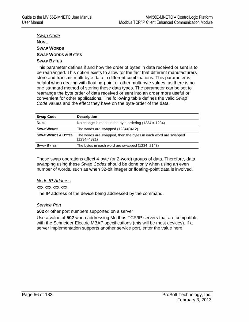
This parameter defines if and how the order of bytes in data received or sent is to be rearranged. This option exists to allow for the fact that different manufacturers store and transmit multi-byte data in different combinations. This parameter is helpful when dealing with floating-point or other multi-byte values, as there is no one standard method of storing these data types. The parameter can be set to rearrange the byte order of data received or sent into an order more useful or convenient for other applications. The following table defines the valid Swap Code values and the effect they have on the byte-order of the data.
Swap Code Description
NONE No change is made in the byte ordering (1234 = 1234)
SWAP WORDS The words are swapped (1234=3412)
SWAP WORDS & BYTES The words are swapped, then the bytes in each word are swapped (1234=4321)
SWAP BYTES The bytes in each word are swapped (1234=2143)
These swap operations affect 4-byte (or 2-word) groups of data. Therefore, data swapping using these Swap Codes should be done only when using an even number of words, such as when 32-bit integer or floating-point data is involved.
Node IP Address
xxx.xxx.xxx.xxx
The IP address of the device being addressed by the command.
Service Port
502 or other port numbers supported on a server
Use a value of 502 when addressing Modbus TCP/IP servers that are compatible with the Schneider Electric MBAP specifications (this will be most devices). If a server implementation supports another service port, enter the value here.

MVI56E-MNETC ♦ ControlLogix Platform Configuring the MVI56E-MNETC Module Modbus TCP/IP Client Enhanced Communication Module User Manual
ProSoft Technology, Inc. Page 57 of 183 February 3, 2013
Slave Address
0 - Broadcast to all nodes
1 to 255
Use this parameter to specify the slave address of a remote Modbus Serial device through a Modbus Ethernet to Serial converter.
Note: Use the Node IP Address parameter (page 56) to address commands to a remote Modbus TCP/IP device. Note: Most Modbus devices accept an address in the range of only 1 to 247, so check with the slave device manufacturer to see if a particular slave can use addresses 248 to 255. If the value is set to zero, the command will be a broadcast message on the network. The Modbus protocol permits broadcast commands for write operations. Do not use node address 0 for read operations.
Modbus Function
1, 2, 3, 4, 5, 6, 7, 15, or 16
This parameter specifies the Modbus Function Code to be executed by the command. These function codes are defined in the Modbus protocol. The following table lists the purpose of each function supported by the module. More information on the protocol is available from www.modbus.org.
Modbus Function Code Description
1 Read Coil Status
2 Read Input Status
3 Read Holding Registers
4 Read Input Registers
5 Force (Write) Single Coil
6 Preset (Write) Single Register
7 Read Exception Status
15 Force Multiple Coils
16 Preset Multiple Registers
Guide to the MVI56E-MNETC User Manual MVI56E-MNETC ♦ ControlLogix Platform User Manual Modbus TCP/IP Client Enhanced Communication Module
Page 58 of 183 ProSoft Technology, Inc. February 3, 2013
MB Address in Device
This parameter specifies the starting Modbus register or bit address in the server to be used by the command. Refer to the documentation of each Modbus server device for the register and bit address assignments valid for that device.
The Modbus Function Code determines whether the address will be a register-level or bit-level OFFSET address into a given data type range. The offset will be the target data address in the server minus the base address for that data type. Base addresses for the different data types are:
00001 or 000001 (0x0001) for bit-level Coil data (Function Codes 1, 5, and 15).
10001 or 100001 (1x0001) for bit-level Input Status data (Function Code 2) 30001 or 300001 (3x0001) for Input Register data (Function Code 4) 40001 or 400001 (4x0001) for Holding Register data (Function Codes 3, 6,
and 16).
Address calculation examples:
For bit-level Coil commands (FC 1, 5, or 15) to read or write a Coil 0X address 00001, specify a value of 0 (00001 - 00001 = 0).
For Coil address 00115, specify 114
(00115 - 00001 = 114)
For register read or write commands (FC 3, 6, or 16) 4X range, for 40001, specify a value of 0
(40001 - 40001 = 0).
For 01101, 11101, 31101 or 41101, specify a value of 1100.
(01101 - 00001 = 1100) (11101 -10001 = 1100) (31101 - 30001 = 1100) (41101 - 40001 = 1100)
Note: If the documentation for a particular Modbus server device lists data addresses in hexadecimal (base16) notation, you will need to convert the hexadecimal value to a decimal value to enter in this parameter. In such cases, it is not usually necessary to subtract 1 from the converted decimal number, as this addressing scheme typically uses the exact offset address expressed as a hexadecimal number.
Comment
0 to 35 alphanumeric characters
MVI56E-MNETC ♦ ControlLogix Platform Configuring the MVI56E-MNETC Module Modbus TCP/IP Client Enhanced Communication Module User Manual
ProSoft Technology, Inc. Page 59 of 183 February 3, 2013
2.2.8 Static ARP Table
The Static ARP Table defines a list of static IP addresses that the module will use when an ARP (Address Resolution Protocol) is required. The module will accept up to 40 static IP/MAC address data sets.
Use the Static ARP table to reduce the amount of network traffic by specifying IP addresses and their associated MAC (hardware) addresses that the MVI56E-MNETC module will be communicating with regularly.
Important: If the device in the field is changed, this table must be updated to contain the new MAC address for the device and downloaded to the module. If the MAC is not changed, no communications with the module will be provided.
IP Address
Dotted notation
This table contains a list of static IP addresses that the module will use when an ARP is required. The module will accept up to 40 static IP/MAC address data sets.
Important: If the device in the field is changed, this table must be updated to contain the new MAC address for the device and downloaded to the module. If the MAC is not changed, no communications with the module will occur.
Hardware MAC Address
Hex value
This table contains a list of static MAC addresses that the module will use when an ARP is required. The module will accept up to 40 static IP/MAC address data sets.
Important: If the device in the field is changed, this table must be updated to contain the new MAC address for the device and downloaded to the module. If the MAC is not changed, no communications with the module will occur.
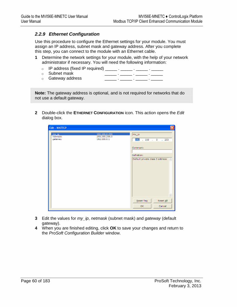
Guide to the MVI56E-MNETC User Manual MVI56E-MNETC ♦ ControlLogix Platform User Manual Modbus TCP/IP Client Enhanced Communication Module
Page 60 of 183 ProSoft Technology, Inc. February 3, 2013
2.2.9 Ethernet Configuration
Use this procedure to configure the Ethernet settings for your module. You must assign an IP address, subnet mask and gateway address. After you complete this step, you can connect to the module with an Ethernet cable.
1 Determine the network settings for your module, with the help of your network administrator if necessary. You will need the following information:
o IP address (fixed IP required) _____ . _____ . _____ . _____ o Subnet mask _____ . _____ . _____ . _____ o Gateway address _____ . _____ . _____ . _____
Note: The gateway address is optional, and is not required for networks that do not use a default gateway.
2 Double-click the ETHERNET CONFIGURATION icon. This action opens the Edit dialog box.
3 Edit the values for my_ip, netmask (subnet mask) and gateway (default gateway).
4 When you are finished editing, click OK to save your changes and return to the ProSoft Configuration Builder window.
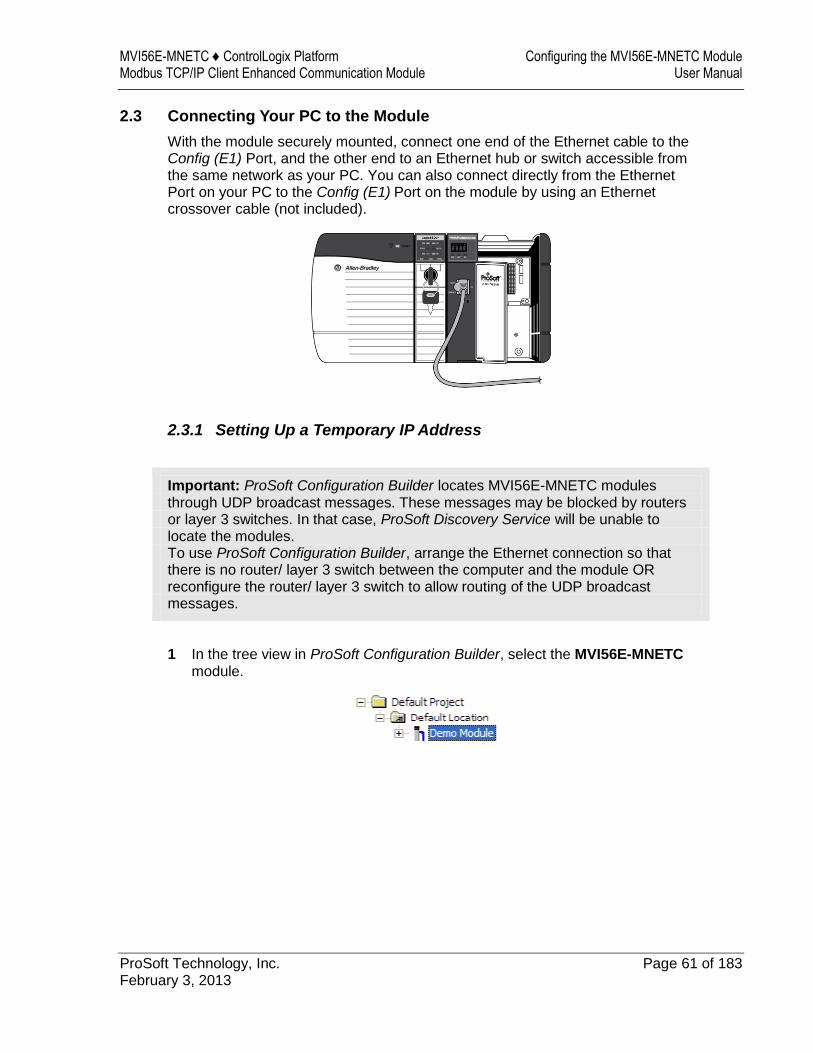
MVI56E-MNETC ♦ ControlLogix Platform Configuring the MVI56E-MNETC Module Modbus TCP/IP Client Enhanced Communication Module User Manual
ProSoft Technology, Inc. Page 61 of 183 February 3, 2013
2.3 Connecting Your PC to the Module
With the module securely mounted, connect one end of the Ethernet cable to the Config (E1) Port, and the other end to an Ethernet hub or switch accessible from the same network as your PC. You can also connect directly from the Ethernet Port on your PC to the Config (E1) Port on the module by using an Ethernet crossover cable (not included).
2.3.1 Setting Up a Temporary IP Address
Important: ProSoft Configuration Builder locates MVI56E-MNETC modules through UDP broadcast messages. These messages may be blocked by routers or layer 3 switches. In that case, ProSoft Discovery Service will be unable to locate the modules. To use ProSoft Configuration Builder, arrange the Ethernet connection so that there is no router/ layer 3 switch between the computer and the module OR reconfigure the router/ layer 3 switch to allow routing of the UDP broadcast messages.
1 In the tree view in ProSoft Configuration Builder, select the MVI56E-MNETC module.
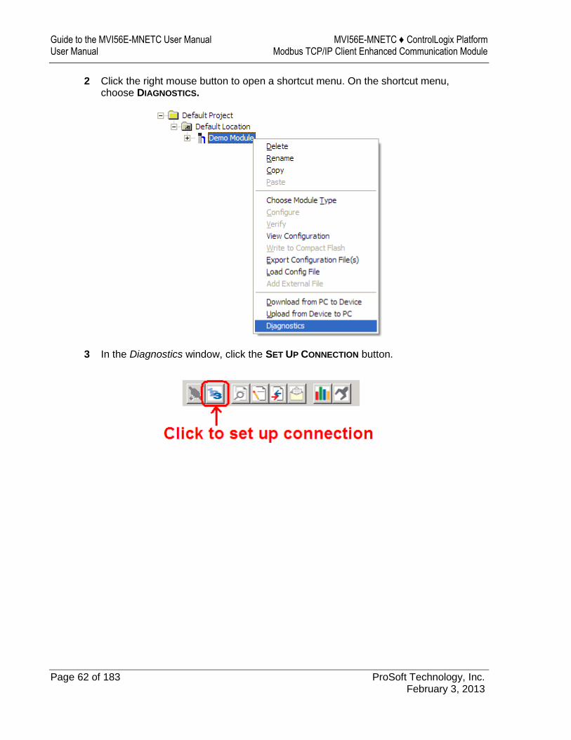
Guide to the MVI56E-MNETC User Manual MVI56E-MNETC ♦ ControlLogix Platform User Manual Modbus TCP/IP Client Enhanced Communication Module
Page 62 of 183 ProSoft Technology, Inc. February 3, 2013
2 Click the right mouse button to open a shortcut menu. On the shortcut menu, choose DIAGNOSTICS.
3 In the Diagnostics window, click the SET UP CONNECTION button.
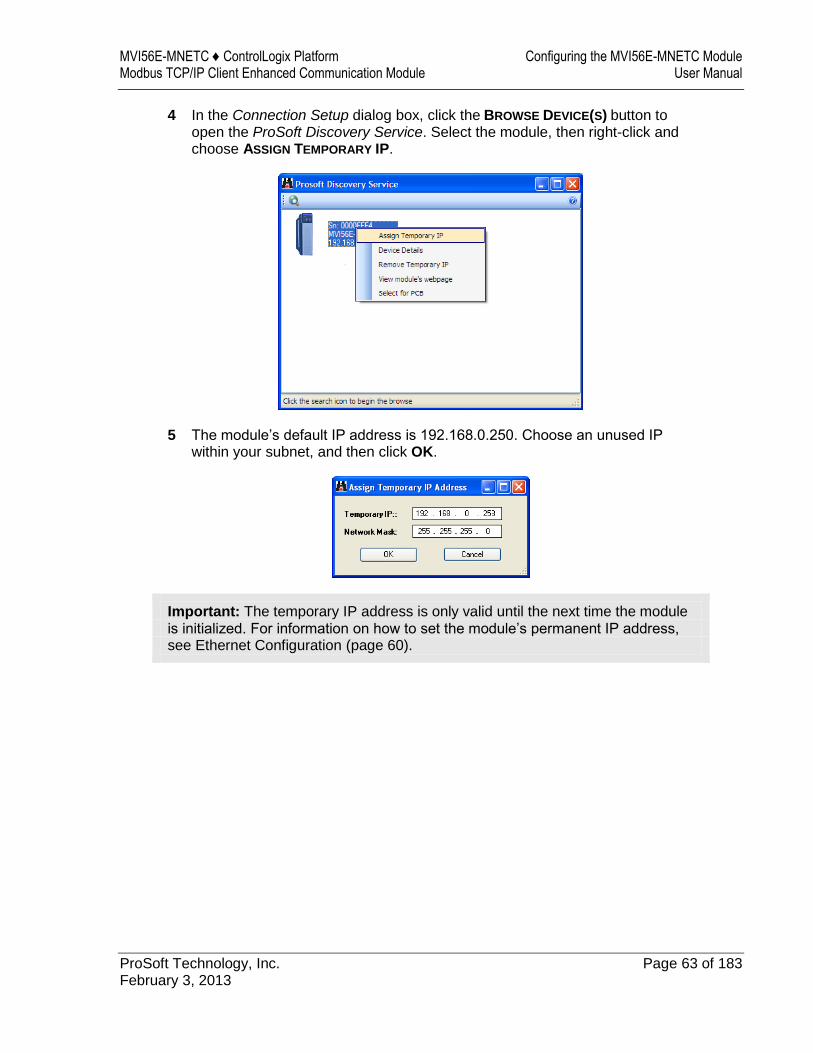
MVI56E-MNETC ♦ ControlLogix Platform Configuring the MVI56E-MNETC Module Modbus TCP/IP Client Enhanced Communication Module User Manual
ProSoft Technology, Inc. Page 63 of 183 February 3, 2013
4 In the Connection Setup dialog box, click the BROWSE DEVICE(S) button to open the ProSoft Discovery Service. Select the module, then right-click and choose ASSIGN TEMPORARY IP.
5 The module’s default IP address is 192.168.0.250. Choose an unused IP within your subnet, and then click OK.
Important: The temporary IP address is only valid until the next time the module is initialized. For information on how to set the module’s permanent IP address, see Ethernet Configuration (page 60).
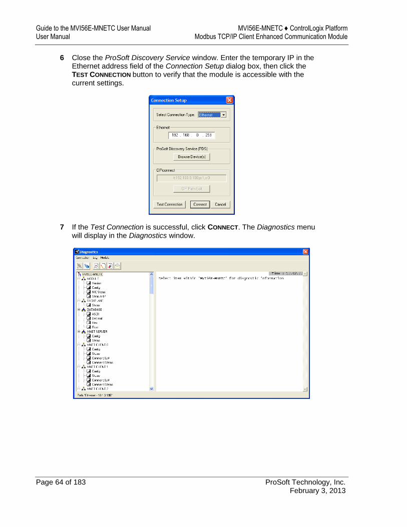
Guide to the MVI56E-MNETC User Manual MVI56E-MNETC ♦ ControlLogix Platform User Manual Modbus TCP/IP Client Enhanced Communication Module
Page 64 of 183 ProSoft Technology, Inc. February 3, 2013
6 Close the ProSoft Discovery Service window. Enter the temporary IP in the Ethernet address field of the Connection Setup dialog box, then click the TEST CONNECTION button to verify that the module is accessible with the current settings.
7 If the Test Connection is successful, click CONNECT. The Diagnostics menu will display in the Diagnostics window.
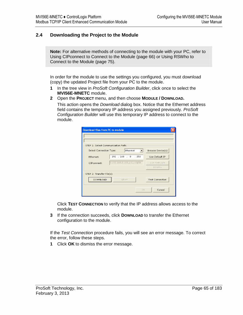
MVI56E-MNETC ♦ ControlLogix Platform Configuring the MVI56E-MNETC Module Modbus TCP/IP Client Enhanced Communication Module User Manual
ProSoft Technology, Inc. Page 65 of 183 February 3, 2013
2.4 Downloading the Project to the Module
Note: For alternative methods of connecting to the module with your PC, refer to Using CIPconnect to Connect to the Module (page 66) or Using RSWho to Connect to the Module (page 75).
In order for the module to use the settings you configured, you must download (copy) the updated Project file from your PC to the module.
1 In the tree view in ProSoft Configuration Builder, click once to select the MVI56E-MNETC module.
2 Open the PROJECT menu, and then choose MODULE / DOWNLOAD.
This action opens the Download dialog box. Notice that the Ethernet address field contains the temporary IP address you assigned previously. ProSoft Configuration Builder will use this temporary IP address to connect to the module.
Click TEST CONNECTION to verify that the IP address allows access to the module.
3 If the connection succeeds, click DOWNLOAD to transfer the Ethernet configuration to the module.
If the Test Connection procedure fails, you will see an error message. To correct the error, follow these steps.
1 Click OK to dismiss the error message.
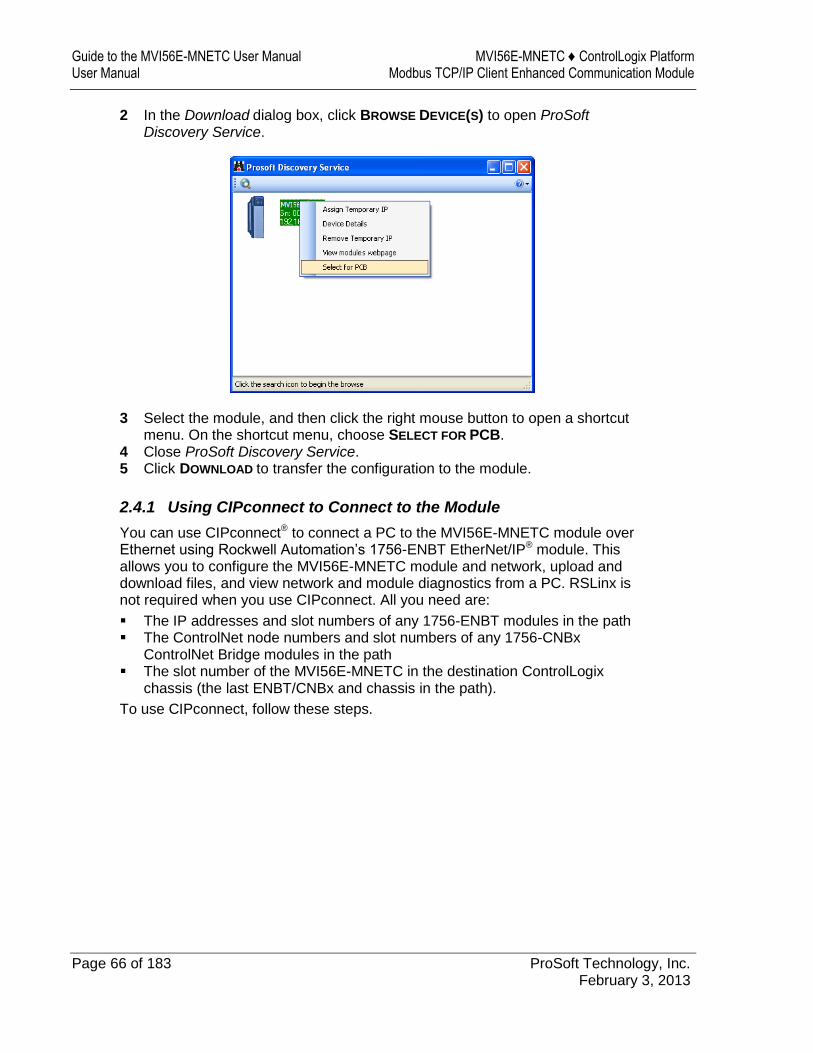
Guide to the MVI56E-MNETC User Manual MVI56E-MNETC ♦ ControlLogix Platform User Manual Modbus TCP/IP Client Enhanced Communication Module
Page 66 of 183 ProSoft Technology, Inc. February 3, 2013
2 In the Download dialog box, click BROWSE DEVICE(S) to open ProSoft Discovery Service.
3 Select the module, and then click the right mouse button to open a shortcut menu. On the shortcut menu, choose SELECT FOR PCB.
4 Close ProSoft Discovery Service. 5 Click DOWNLOAD to transfer the configuration to the module.
2.4.1 Using CIPconnect to Connect to the Module
You can use CIPconnect® to connect a PC to the MVI56E-MNETC module over Ethernet using Rockwell Automation’s 1756-ENBT EtherNet/IP® module. This allows you to configure the MVI56E-MNETC module and network, upload and download files, and view network and module diagnostics from a PC. RSLinx is not required when you use CIPconnect. All you need are:
The IP addresses and slot numbers of any 1756-ENBT modules in the path The ControlNet node numbers and slot numbers of any 1756-CNBx
ControlNet Bridge modules in the path The slot number of the MVI56E-MNETC in the destination ControlLogix
chassis (the last ENBT/CNBx and chassis in the path).
To use CIPconnect, follow these steps.
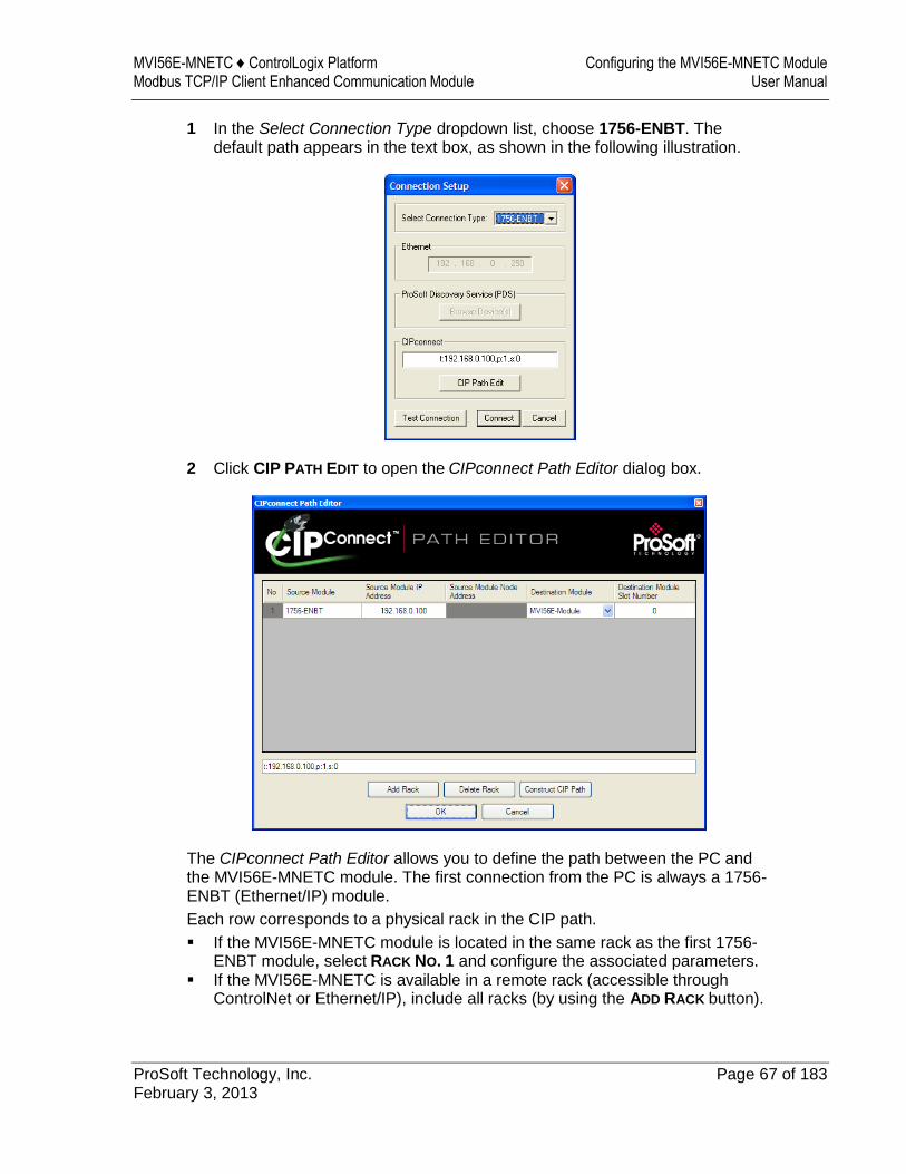
MVI56E-MNETC ♦ ControlLogix Platform Configuring the MVI56E-MNETC Module Modbus TCP/IP Client Enhanced Communication Module User Manual
ProSoft Technology, Inc. Page 67 of 183 February 3, 2013
1 In the Select Connection Type dropdown list, choose 1756-ENBT. The default path appears in the text box, as shown in the following illustration.
2 Click CIP PATH EDIT to open the CIPconnect Path Editor dialog box.
The CIPconnect Path Editor allows you to define the path between the PC and the MVI56E-MNETC module. The first connection from the PC is always a 1756-ENBT (Ethernet/IP) module.
Each row corresponds to a physical rack in the CIP path.
If the MVI56E-MNETC module is located in the same rack as the first 1756-ENBT module, select RACK NO. 1 and configure the associated parameters.
If the MVI56E-MNETC is available in a remote rack (accessible through ControlNet or Ethernet/IP), include all racks (by using the ADD RACK button).
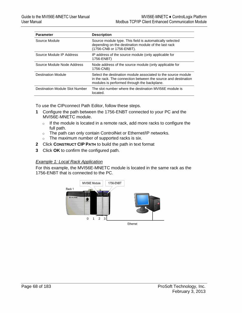
Guide to the MVI56E-MNETC User Manual MVI56E-MNETC ♦ ControlLogix Platform User Manual Modbus TCP/IP Client Enhanced Communication Module
Page 68 of 183 ProSoft Technology, Inc. February 3, 2013
Parameter Description
Source Module Source module type. This field is automatically selected depending on the destination module of the last rack (1756-CNB or 1756-ENBT).
Source Module IP Address IP address of the source module (only applicable for 1756-ENBT)
Source Module Node Address Node address of the source module (only applicable for 1756-CNB)
Destination Module Select the destination module associated to the source module in the rack. The connection between the source and destination modules is performed through the backplane.
Destination Module Slot Number The slot number where the destination MVI56E module is located.
To use the CIPconnect Path Editor, follow these steps.
1 Configure the path between the 1756-ENBT connected to your PC and the MVI56E-MNETC module.
o If the module is located in a remote rack, add more racks to configure the full path.
o The path can only contain ControlNet or Ethernet/IP networks. o The maximum number of supported racks is six.
2 Click CONSTRUCT CIP PATH to build the path in text format
3 Click OK to confirm the configured path.
Example 1: Local Rack Application
For this example, the MVI56E-MNETC module is located in the same rack as the 1756-ENBT that is connected to the PC.
Ethernet
Rack 1
MVI56E Module 1756-ENBT
0 1 2 3
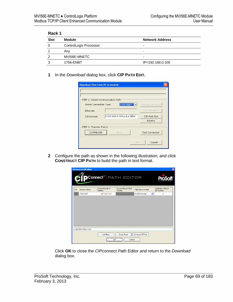
MVI56E-MNETC ♦ ControlLogix Platform Configuring the MVI56E-MNETC Module Modbus TCP/IP Client Enhanced Communication Module User Manual
ProSoft Technology, Inc. Page 69 of 183 February 3, 2013
Rack 1
Slot Module Network Address
0 ControlLogix Processor -
1 Any -
2 MVI56E-MNETC -
3 1756-ENBT IP=192.168.0.100
1 In the Download dialog box, click CIP PATH EDIT.
2 Configure the path as shown in the following illustration, and click CONSTRUCT CIP PATH to build the path in text format.
Click OK to close the CIPconnect Path Editor and return to the Download
dialog box.
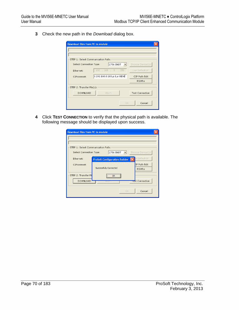
Guide to the MVI56E-MNETC User Manual MVI56E-MNETC ♦ ControlLogix Platform User Manual Modbus TCP/IP Client Enhanced Communication Module
Page 70 of 183 ProSoft Technology, Inc. February 3, 2013
3 Check the new path in the Download dialog box.
4 Click TEST CONNECTION to verify that the physical path is available. The following message should be displayed upon success.
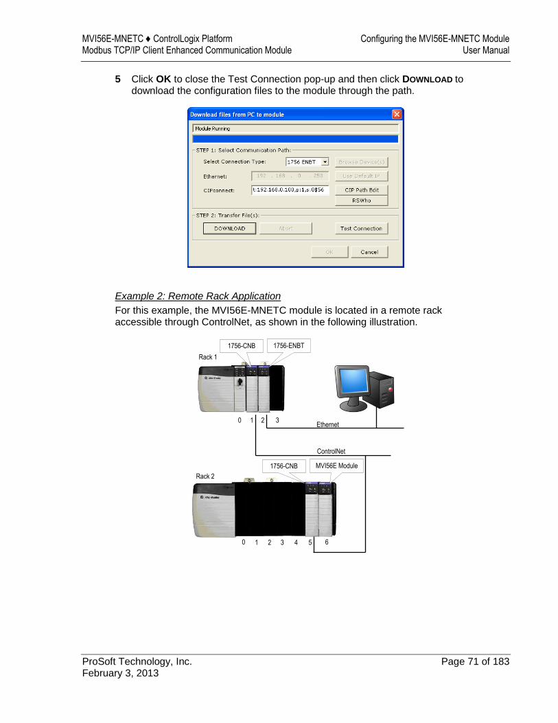
MVI56E-MNETC ♦ ControlLogix Platform Configuring the MVI56E-MNETC Module Modbus TCP/IP Client Enhanced Communication Module User Manual
ProSoft Technology, Inc. Page 71 of 183 February 3, 2013
5 Click OK to close the Test Connection pop-up and then click DOWNLOAD to download the configuration files to the module through the path.
Example 2: Remote Rack Application
For this example, the MVI56E-MNETC module is located in a remote rack accessible through ControlNet, as shown in the following illustration.
Ethernet
Rack 1
0 1 2 3
ControlNet
0 1 2 3 4 5 6
Rack 2
1756-ENBT1756-CNB
1756-CNB MVI56E Module
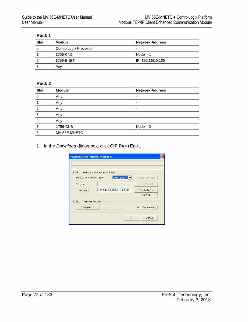
Guide to the MVI56E-MNETC User Manual MVI56E-MNETC ♦ ControlLogix Platform User Manual Modbus TCP/IP Client Enhanced Communication Module
Page 72 of 183 ProSoft Technology, Inc. February 3, 2013
Rack 1
Slot Module Network Address
0 ControlLogix Processor -
1 1756-CNB Node = 1
2 1756-ENBT IP=192.168.0.100
3 Any -
Rack 2
Slot Module Network Address
0 Any -
1 Any -
2 Any -
3 Any -
4 Any -
5 1756-CNB Node = 2
6 MVI56E-MNETC -
1 In the Download dialog box, click CIP PATH EDIT.
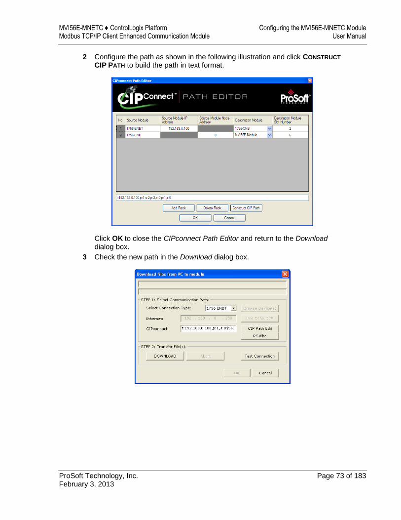
MVI56E-MNETC ♦ ControlLogix Platform Configuring the MVI56E-MNETC Module Modbus TCP/IP Client Enhanced Communication Module User Manual
ProSoft Technology, Inc. Page 73 of 183 February 3, 2013
2 Configure the path as shown in the following illustration and click CONSTRUCT
CIP PATH to build the path in text format.
Click OK to close the CIPconnect Path Editor and return to the Download
dialog box.
3 Check the new path in the Download dialog box.
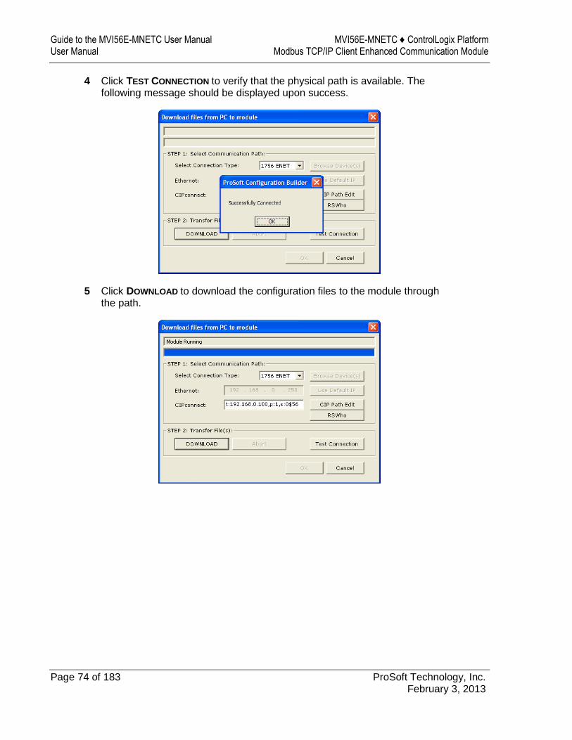
Guide to the MVI56E-MNETC User Manual MVI56E-MNETC ♦ ControlLogix Platform User Manual Modbus TCP/IP Client Enhanced Communication Module
Page 74 of 183 ProSoft Technology, Inc. February 3, 2013
4 Click TEST CONNECTION to verify that the physical path is available. The following message should be displayed upon success.
5 Click DOWNLOAD to download the configuration files to the module through the path.
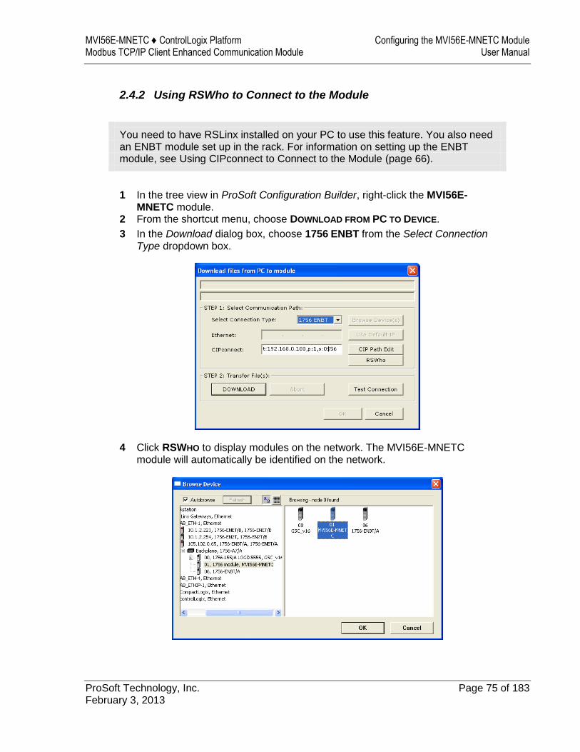
MVI56E-MNETC ♦ ControlLogix Platform Configuring the MVI56E-MNETC Module Modbus TCP/IP Client Enhanced Communication Module User Manual
ProSoft Technology, Inc. Page 75 of 183 February 3, 2013
2.4.2 Using RSWho to Connect to the Module
You need to have RSLinx installed on your PC to use this feature. You also need an ENBT module set up in the rack. For information on setting up the ENBT module, see Using CIPconnect to Connect to the Module (page 66).
1 In the tree view in ProSoft Configuration Builder, right-click the MVI56E-MNETC module.
2 From the shortcut menu, choose DOWNLOAD FROM PC TO DEVICE.
3 In the Download dialog box, choose 1756 ENBT from the Select Connection Type dropdown box.
4 Click RSWHO to display modules on the network. The MVI56E-MNETC module will automatically be identified on the network.

Guide to the MVI56E-MNETC User Manual MVI56E-MNETC ♦ ControlLogix Platform User Manual Modbus TCP/IP Client Enhanced Communication Module
Page 76 of 183 ProSoft Technology, Inc. February 3, 2013
5 Select the module, and then click OK.
6 In the Download dialog box, click DOWNLOAD.
MVI56E-MNETC ♦ ControlLogix Platform Ladder Logic Modbus TCP/IP Client Enhanced Communication Module User Manual
ProSoft Technology, Inc. Page 77 of 183 February 3, 2013
3 Ladder Logic
In This Chapter
Controller Tags ...................................................................................... 78
User-Defined Data Types (UDTs) ......................................................... 80
Using Controller Tags ............................................................................ 82
Controller Tag Overview ........................................................................ 82
Ladder logic is required for managing communication between the MVI56E-MNETC module and the processor. The ladder logic handles tasks such as:
Module backplane data transfer Special block handling Status data receipt
Additionally, a power-up handler may be needed to initialize the module’s database and may clear some processor fault conditions.
The sample Import Rung with Add-On Instruction is extensively commented to provide information on the purpose and function of each user-defined data type and controller tag. For most applications, the Import Rung with Add-On Instruction will work without modification.
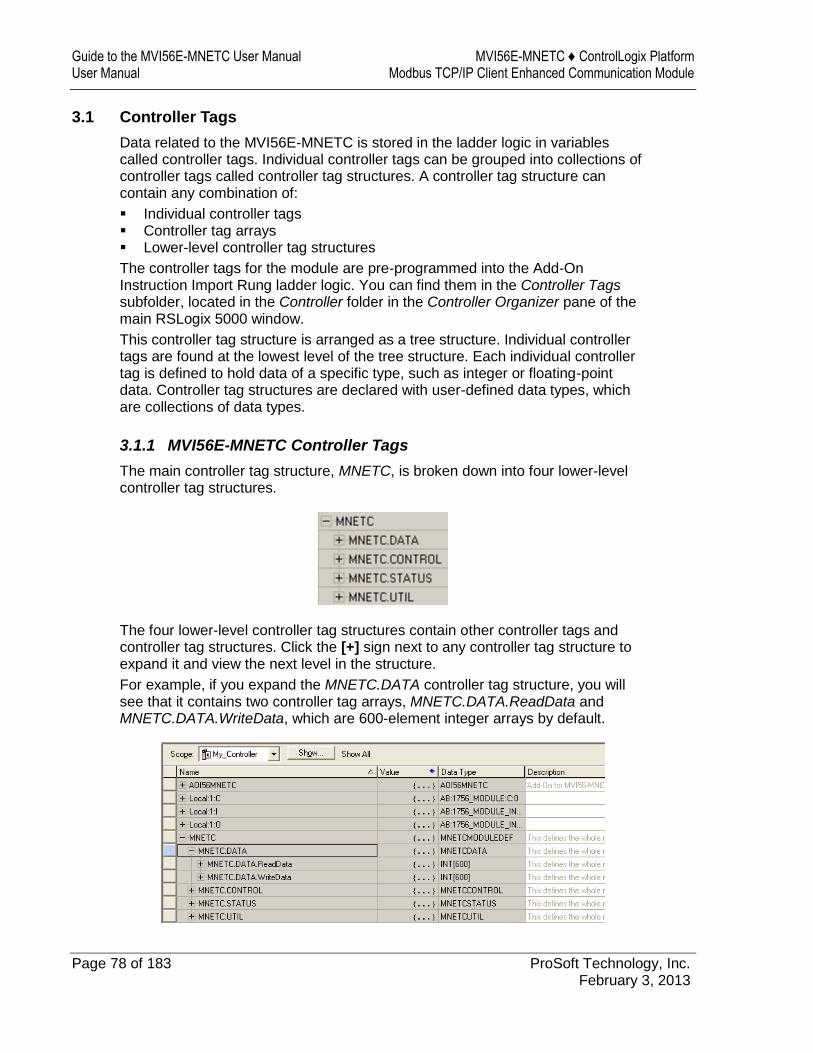
Guide to the MVI56E-MNETC User Manual MVI56E-MNETC ♦ ControlLogix Platform User Manual Modbus TCP/IP Client Enhanced Communication Module
Page 78 of 183 ProSoft Technology, Inc. February 3, 2013
3.1 Controller Tags
Data related to the MVI56E-MNETC is stored in the ladder logic in variables called controller tags. Individual controller tags can be grouped into collections of controller tags called controller tag structures. A controller tag structure can contain any combination of:
Individual controller tags Controller tag arrays Lower-level controller tag structures
The controller tags for the module are pre-programmed into the Add-On Instruction Import Rung ladder logic. You can find them in the Controller Tags subfolder, located in the Controller folder in the Controller Organizer pane of the main RSLogix 5000 window.
This controller tag structure is arranged as a tree structure. Individual controller tags are found at the lowest level of the tree structure. Each individual controller tag is defined to hold data of a specific type, such as integer or floating-point data. Controller tag structures are declared with user-defined data types, which are collections of data types.
3.1.1 MVI56E-MNETC Controller Tags
The main controller tag structure, MNETC, is broken down into four lower-level controller tag structures.
The four lower-level controller tag structures contain other controller tags and controller tag structures. Click the [+] sign next to any controller tag structure to expand it and view the next level in the structure.
For example, if you expand the MNETC.DATA controller tag structure, you will see that it contains two controller tag arrays, MNETC.DATA.ReadData and MNETC.DATA.WriteData, which are 600-element integer arrays by default.

MVI56E-MNETC ♦ ControlLogix Platform Ladder Logic Modbus TCP/IP Client Enhanced Communication Module User Manual
ProSoft Technology, Inc. Page 79 of 183 February 3, 2013
Each controller tag in the Add-On Instruction is commented in the Description column.
Notice that the Data Type column displays the data types used to declare each controller tag, controller tag array or controller tag structure. Individual controller tags are declared with basic data types, such as INT and BOOL. Controller tag arrays are declared with arrays of basic data types. Controller tag structures are declared with user-defined data types (UDTs).
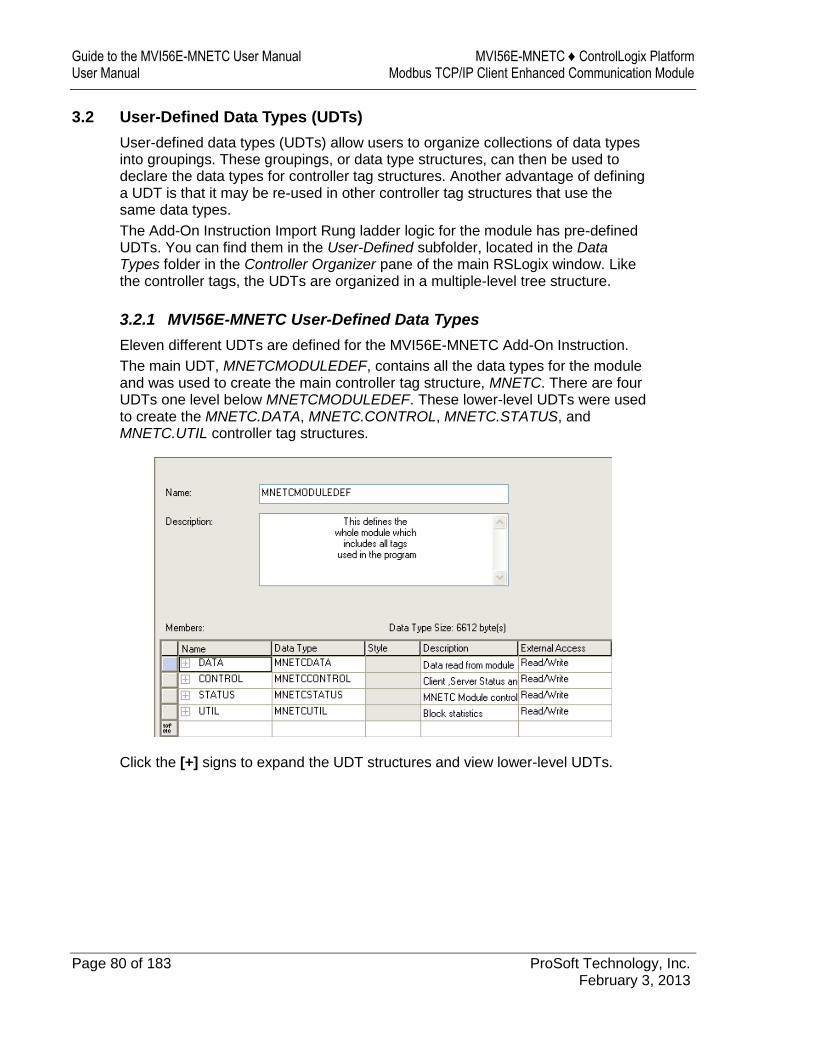
Guide to the MVI56E-MNETC User Manual MVI56E-MNETC ♦ ControlLogix Platform User Manual Modbus TCP/IP Client Enhanced Communication Module
Page 80 of 183 ProSoft Technology, Inc. February 3, 2013
3.2 User-Defined Data Types (UDTs)
User-defined data types (UDTs) allow users to organize collections of data types into groupings. These groupings, or data type structures, can then be used to declare the data types for controller tag structures. Another advantage of defining a UDT is that it may be re-used in other controller tag structures that use the same data types.
The Add-On Instruction Import Rung ladder logic for the module has pre-defined UDTs. You can find them in the User-Defined subfolder, located in the Data Types folder in the Controller Organizer pane of the main RSLogix window. Like the controller tags, the UDTs are organized in a multiple-level tree structure.
3.2.1 MVI56E-MNETC User-Defined Data Types
Eleven different UDTs are defined for the MVI56E-MNETC Add-On Instruction.
The main UDT, MNETCMODULEDEF, contains all the data types for the module and was used to create the main controller tag structure, MNETC. There are four UDTs one level below MNETCMODULEDEF. These lower-level UDTs were used to create the MNETC.DATA, MNETC.CONTROL, MNETC.STATUS, and MNETC.UTIL controller tag structures.
Click the [+] signs to expand the UDT structures and view lower-level UDTs.
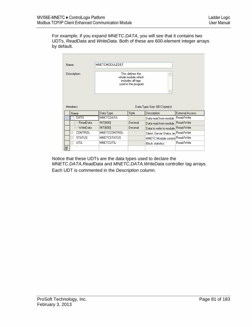
MVI56E-MNETC ♦ ControlLogix Platform Ladder Logic Modbus TCP/IP Client Enhanced Communication Module User Manual
ProSoft Technology, Inc. Page 81 of 183 February 3, 2013
For example, if you expand MNETC.DATA, you will see that it contains two UDTs, ReadData and WriteData. Both of these are 600-element integer arrays by default.
Notice that these UDTs are the data types used to declare the MNETC.DATA.ReadData and MNETC.DATA.WriteData controller tag arrays.
Each UDT is commented in the Description column.
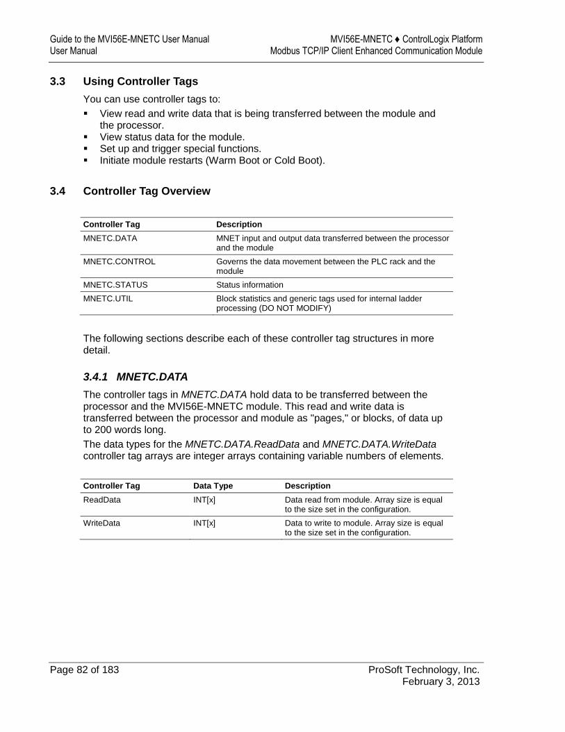
Guide to the MVI56E-MNETC User Manual MVI56E-MNETC ♦ ControlLogix Platform User Manual Modbus TCP/IP Client Enhanced Communication Module
Page 82 of 183 ProSoft Technology, Inc. February 3, 2013
3.3 Using Controller Tags
You can use controller tags to:
View read and write data that is being transferred between the module and the processor.
View status data for the module. Set up and trigger special functions. Initiate module restarts (Warm Boot or Cold Boot).
3.4 Controller Tag Overview
Controller Tag Description
MNETC.DATA MNET input and output data transferred between the processor and the module
MNETC.CONTROL Governs the data movement between the PLC rack and the module
MNETC.STATUS Status information
MNETC.UTIL Block statistics and generic tags used for internal ladder processing (DO NOT MODIFY)
The following sections describe each of these controller tag structures in more detail.
3.4.1 MNETC.DATA
The controller tags in MNETC.DATA hold data to be transferred between the processor and the MVI56E-MNETC module. This read and write data is transferred between the processor and module as "pages," or blocks, of data up to 200 words long.
The data types for the MNETC.DATA.ReadData and MNETC.DATA.WriteData controller tag arrays are integer arrays containing variable numbers of elements.
Controller Tag Data Type Description
ReadData INT[x] Data read from module. Array size is equal to the size set in the configuration.
WriteData INT[x] Data to write to module. Array size is equal to the size set in the configuration.
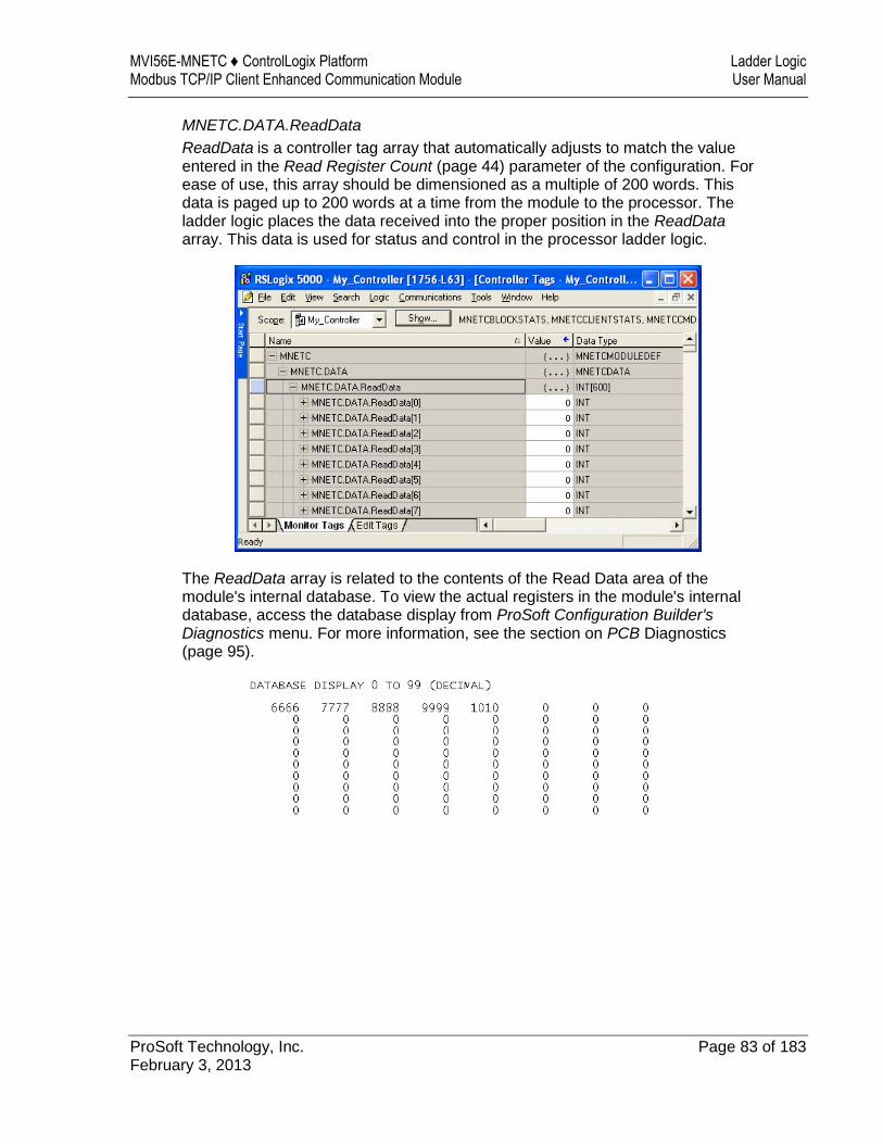
MVI56E-MNETC ♦ ControlLogix Platform Ladder Logic Modbus TCP/IP Client Enhanced Communication Module User Manual
ProSoft Technology, Inc. Page 83 of 183 February 3, 2013
MNETC.DATA.ReadData
ReadData is a controller tag array that automatically adjusts to match the value entered in the Read Register Count (page 44) parameter of the configuration. For ease of use, this array should be dimensioned as a multiple of 200 words. This data is paged up to 200 words at a time from the module to the processor. The ladder logic places the data received into the proper position in the ReadData array. This data is used for status and control in the processor ladder logic.
The ReadData array is related to the contents of the Read Data area of the module's internal database. To view the actual registers in the module's internal database, access the database display from ProSoft Configuration Builder's Diagnostics menu. For more information, see the section on PCB Diagnostics (page 95).
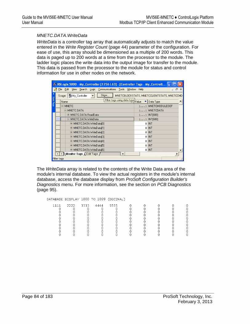
Guide to the MVI56E-MNETC User Manual MVI56E-MNETC ♦ ControlLogix Platform User Manual Modbus TCP/IP Client Enhanced Communication Module
Page 84 of 183 ProSoft Technology, Inc. February 3, 2013
MNETC.DATA.WriteData
WriteData is a controller tag array that automatically adjusts to match the value entered in the Write Register Count (page 44) parameter of the configuration. For ease of use, this array should be dimensioned as a multiple of 200 words. This data is paged up to 200 words at a time from the processor to the module. The ladder logic places the write data into the output image for transfer to the module. This data is passed from the processor to the module for status and control information for use in other nodes on the network.
The WriteData array is related to the contents of the Write Data area of the module's internal database. To view the actual registers in the module's internal database, access the database display from ProSoft Configuration Builder's Diagnostics menu. For more information, see the section on PCB Diagnostics (page 95).
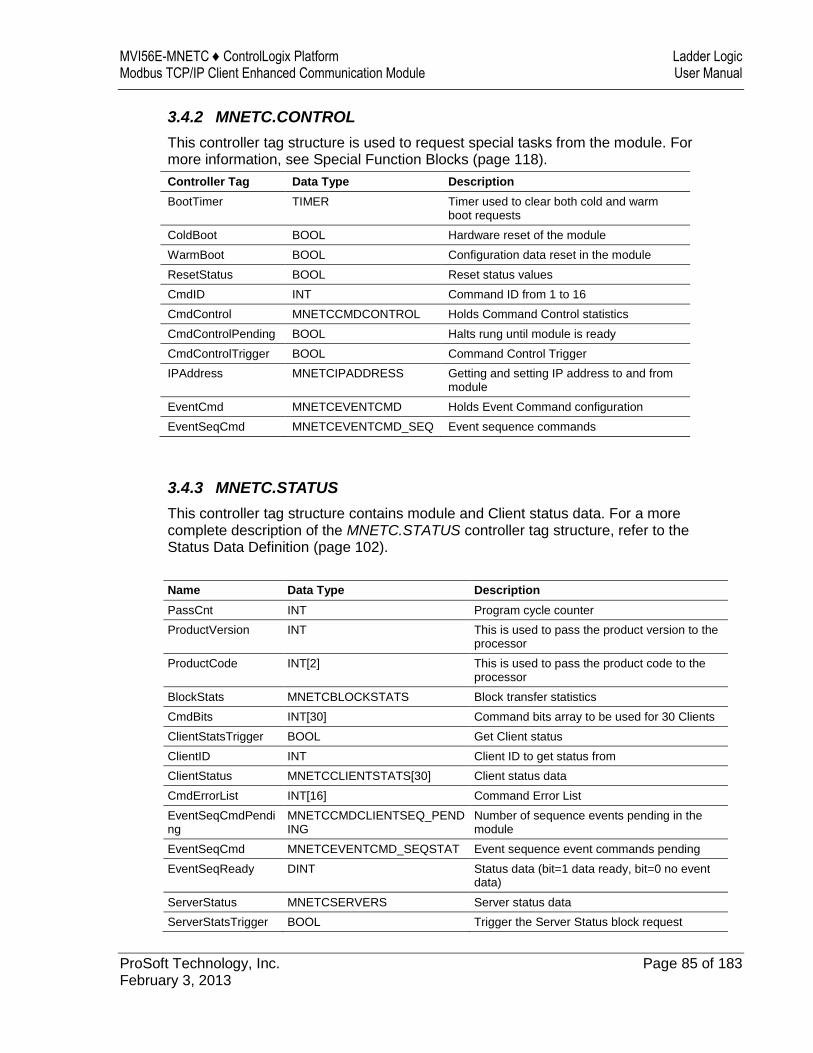
MVI56E-MNETC ♦ ControlLogix Platform Ladder Logic Modbus TCP/IP Client Enhanced Communication Module User Manual
ProSoft Technology, Inc. Page 85 of 183 February 3, 2013
3.4.2 MNETC.CONTROL
This controller tag structure is used to request special tasks from the module. For more information, see Special Function Blocks (page 118).
Controller Tag Data Type Description
BootTimer TIMER Timer used to clear both cold and warm boot requests
ColdBoot BOOL Hardware reset of the module
WarmBoot BOOL Configuration data reset in the module
ResetStatus BOOL Reset status values
CmdID INT Command ID from 1 to 16
CmdControl MNETCCMDCONTROL Holds Command Control statistics
CmdControlPending BOOL Halts rung until module is ready
CmdControlTrigger BOOL Command Control Trigger
IPAddress MNETCIPADDRESS Getting and setting IP address to and from module
EventCmd MNETCEVENTCMD Holds Event Command configuration
EventSeqCmd MNETCEVENTCMD_SEQ Event sequence commands
3.4.3 MNETC.STATUS
This controller tag structure contains module and Client status data. For a more complete description of the MNETC.STATUS controller tag structure, refer to the Status Data Definition (page 102).
Name Data Type Description
PassCnt INT Program cycle counter
ProductVersion INT This is used to pass the product version to the processor
ProductCode INT[2] This is used to pass the product code to the processor
BlockStats MNETCBLOCKSTATS Block transfer statistics
CmdBits INT[30] Command bits array to be used for 30 Clients
ClientStatsTrigger BOOL Get Client status
ClientID INT Client ID to get status from
ClientStatus MNETCCLIENTSTATS[30] Client status data
CmdErrorList INT[16] Command Error List
EventSeqCmdPending
MNETCCMDCLIENTSEQ_PENDING
Number of sequence events pending in the module
EventSeqCmd MNETCEVENTCMD_SEQSTAT Event sequence event commands pending
EventSeqReady DINT Status data (bit=1 data ready, bit=0 no event data)
ServerStatus MNETCSERVERS Server status data
ServerStatsTrigger BOOL Trigger the Server Status block request
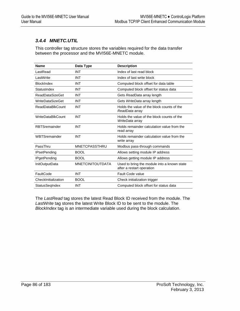
Guide to the MVI56E-MNETC User Manual MVI56E-MNETC ♦ ControlLogix Platform User Manual Modbus TCP/IP Client Enhanced Communication Module
Page 86 of 183 ProSoft Technology, Inc. February 3, 2013
3.4.4 MNETC.UTIL
This controller tag structure stores the variables required for the data transfer between the processor and the MVI56E-MNETC module.
Name Data Type Description
LastRead INT Index of last read block
LastWrite INT Index of last write block
BlockIndex INT Computed block offset for data table
StatusIndex INT Computed block offset for status data
ReadDataSizeGet INT Gets ReadData array length
WriteDataSizeGet INT Gets WriteData array length
ReadDataBlkCount INT Holds the value of the block counts of the ReadData array
WriteDataBlkCount INT Holds the value of the block counts of the WriteData array
RBTSremainder INT Holds remainder calculation value from the read array
WBTSremainder INT Holds remainder calculation value from the write array
PassThru MNETCPASSTHRU Modbus pass-through commands
IPsetPending BOOL Allows setting module IP address
IPgetPending BOOL Allows getting module IP address
InitOutputData MNETCINITOUTDATA Used to bring the module into a known state after a restart operation
FaultCode INT Fault Code value
CheckInitialization BOOL Check initialization trigger
StatusSeqIndex INT Computed block offset for status data
The LastRead tag stores the latest Read Block ID received from the module. The LastWrite tag stores the latest Write Block ID to be sent to the module. The BlockIndex tag is an intermediate variable used during the block calculation.
MVI56E-MNETC ♦ ControlLogix Platform Diagnostics and Troubleshooting Modbus TCP/IP Client Enhanced Communication Module User Manual
ProSoft Technology, Inc. Page 87 of 183 February 3, 2013
4 Diagnostics and Troubleshooting
In This Chapter
LED Status Indicators ............................................................................ 88
Using the Diagnostics Menu in ProSoft Configuration Builder ............... 92
Reading Status Data from the Module ................................................ 101
The module provides information on diagnostics and troubleshooting in the following forms:
LED status indicators on the front of the module provide information on the module’s status.
Status data contained in the module can be viewed in ProSoft Configuration Builder through the Ethernet port.
Status data values are transferred from the module to the processor.
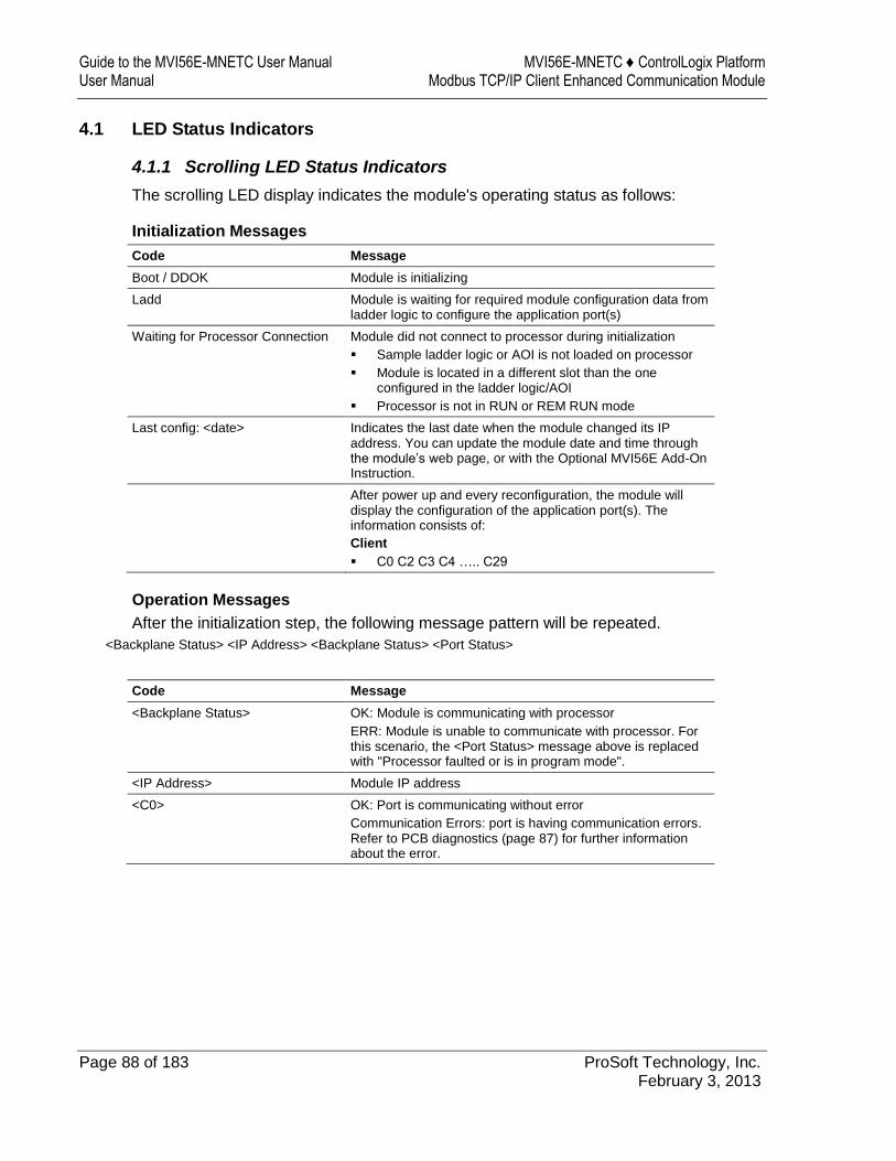
Guide to the MVI56E-MNETC User Manual MVI56E-MNETC ♦ ControlLogix Platform User Manual Modbus TCP/IP Client Enhanced Communication Module
Page 88 of 183 ProSoft Technology, Inc. February 3, 2013
4.1 LED Status Indicators
4.1.1 Scrolling LED Status Indicators
The scrolling LED display indicates the module's operating status as follows:
Initialization Messages
Code Message
Boot / DDOK Module is initializing
Ladd Module is waiting for required module configuration data from ladder logic to configure the application port(s)
Waiting for Processor Connection Module did not connect to processor during initialization
Sample ladder logic or AOI is not loaded on processor
Module is located in a different slot than the one configured in the ladder logic/AOI
Processor is not in RUN or REM RUN mode
Last config: <date> Indicates the last date when the module changed its IP address. You can update the module date and time through the module’s web page, or with the Optional MVI56E Add-On Instruction.
After power up and every reconfiguration, the module will display the configuration of the application port(s). The information consists of:
Client
C0 C2 C3 C4 ….. C29
Operation Messages
After the initialization step, the following message pattern will be repeated.
<Backplane Status> <IP Address> <Backplane Status> <Port Status>
Code Message
<Backplane Status> OK: Module is communicating with processor
ERR: Module is unable to communicate with processor. For this scenario, the <Port Status> message above is replaced with "Processor faulted or is in program mode".
<IP Address> Module IP address
<C0> OK: Port is communicating without error
Communication Errors: port is having communication errors. Refer to PCB diagnostics (page 87) for further information about the error.
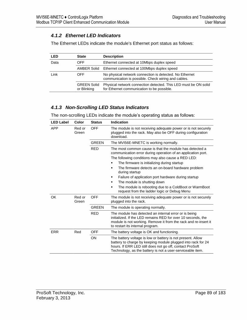
MVI56E-MNETC ♦ ControlLogix Platform Diagnostics and Troubleshooting Modbus TCP/IP Client Enhanced Communication Module User Manual
ProSoft Technology, Inc. Page 89 of 183 February 3, 2013
4.1.2 Ethernet LED Indicators
The Ethernet LEDs indicate the module's Ethernet port status as follows:
LED State Description
Data OFF Ethernet connected at 10Mbps duplex speed
AMBER Solid Ethernet connected at 100Mbps duplex speed
Link OFF No physical network connection is detected. No Ethernet communication is possible. Check wiring and cables.
GREEN Solid or Blinking
Physical network connection detected. This LED must be ON solid for Ethernet communication to be possible.
4.1.3 Non-Scrolling LED Status Indicators
The non-scrolling LEDs indicate the module’s operating status as follows:
LED Label Color Status Indication
APP Red or Green
OFF The module is not receiving adequate power or is not securely plugged into the rack. May also be OFF during configuration download.
GREEN The MVI56E-MNETC is working normally.
RED The most common cause is that the module has detected a communication error during operation of an application port.
The following conditions may also cause a RED LED:
The firmware is initializing during startup
The firmware detects an on-board hardware problem during startup
Failure of application port hardware during startup
The module is shutting down
The module is rebooting due to a ColdBoot or WarmBoot request from the ladder logic or Debug Menu
OK Red or Green
OFF The module is not receiving adequate power or is not securely plugged into the rack.
GREEN The module is operating normally.
RED The module has detected an internal error or is being initialized. If the LED remains RED for over 10 seconds, the module is not working. Remove it from the rack and re-insert it to restart its internal program.
ERR Red OFF The battery voltage is OK and functioning.
ON The battery voltage is low or battery is not present. Allow battery to charge by keeping module plugged into rack for 24 hours. If ERR LED still does not go off, contact ProSoft Technology, as the battery is not a user-serviceable item.
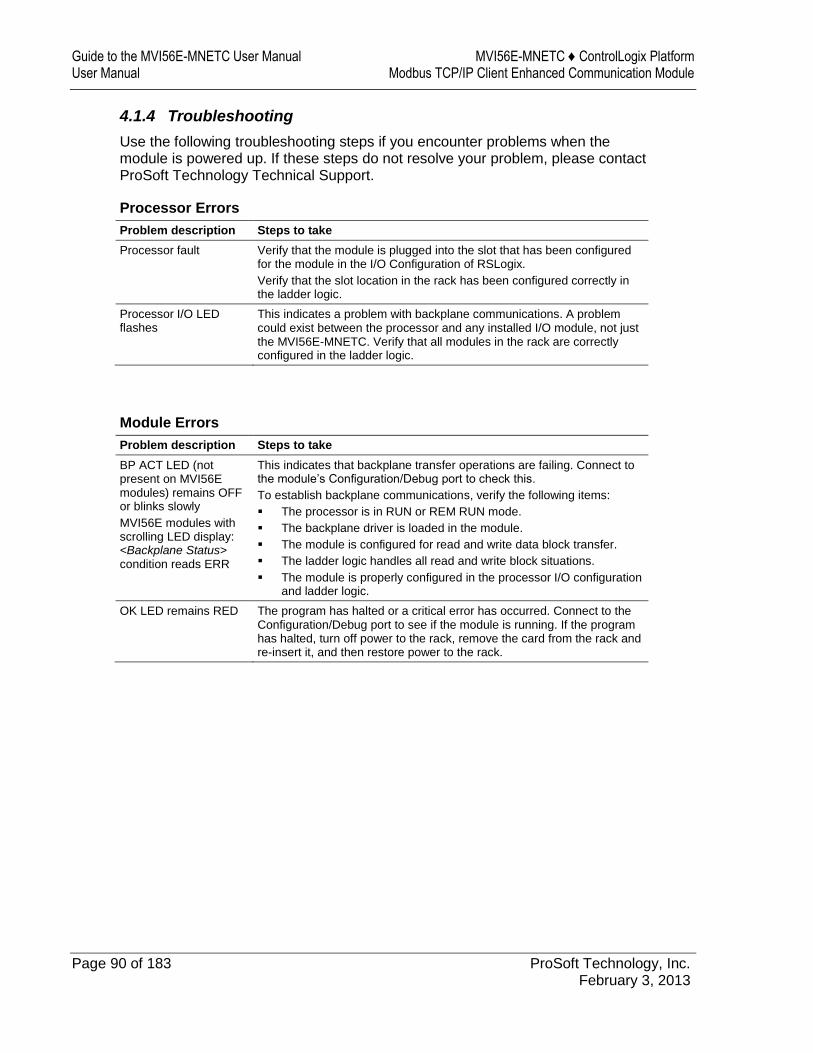
Guide to the MVI56E-MNETC User Manual MVI56E-MNETC ♦ ControlLogix Platform User Manual Modbus TCP/IP Client Enhanced Communication Module
Page 90 of 183 ProSoft Technology, Inc. February 3, 2013
4.1.4 Troubleshooting
Use the following troubleshooting steps if you encounter problems when the module is powered up. If these steps do not resolve your problem, please contact ProSoft Technology Technical Support.
Processor Errors
Problem description Steps to take
Processor fault Verify that the module is plugged into the slot that has been configured for the module in the I/O Configuration of RSLogix.
Verify that the slot location in the rack has been configured correctly in the ladder logic.
Processor I/O LED flashes
This indicates a problem with backplane communications. A problem could exist between the processor and any installed I/O module, not just the MVI56E-MNETC. Verify that all modules in the rack are correctly configured in the ladder logic.
Module Errors
Problem description Steps to take
BP ACT LED (not present on MVI56E modules) remains OFF or blinks slowly
MVI56E modules with scrolling LED display: <Backplane Status> condition reads ERR
This indicates that backplane transfer operations are failing. Connect to the module’s Configuration/Debug port to check this.
To establish backplane communications, verify the following items:
The processor is in RUN or REM RUN mode.
The backplane driver is loaded in the module.
The module is configured for read and write data block transfer.
The ladder logic handles all read and write block situations.
The module is properly configured in the processor I/O configuration and ladder logic.
OK LED remains RED The program has halted or a critical error has occurred. Connect to the Configuration/Debug port to see if the module is running. If the program has halted, turn off power to the rack, remove the card from the rack and re-insert it, and then restore power to the rack.

MVI56E-MNETC ♦ ControlLogix Platform Diagnostics and Troubleshooting Modbus TCP/IP Client Enhanced Communication Module User Manual
ProSoft Technology, Inc. Page 91 of 183 February 3, 2013
4.1.5 Clearing a Fault Condition
Typically, if the OK LED on the front of the module turns RED for more than ten seconds, a hardware problem has been detected in the module or the program has exited.
To clear the condition, follow these steps:
1 Turn off power to the rack. 2 Remove the card from the rack. 3 Verify that all jumpers are set correctly. 4 If the module requires a Compact Flash card, verify that the card is installed
correctly. 5 Re-insert the card in the rack and turn the power back on. 6 Verify correct configuration data is being transferred to the module from the
ControlLogix controller.
If the module's OK LED does not turn GREEN, verify that the module is inserted completely into the rack. If this does not cure the problem, contact ProSoft Technology Technical Support.
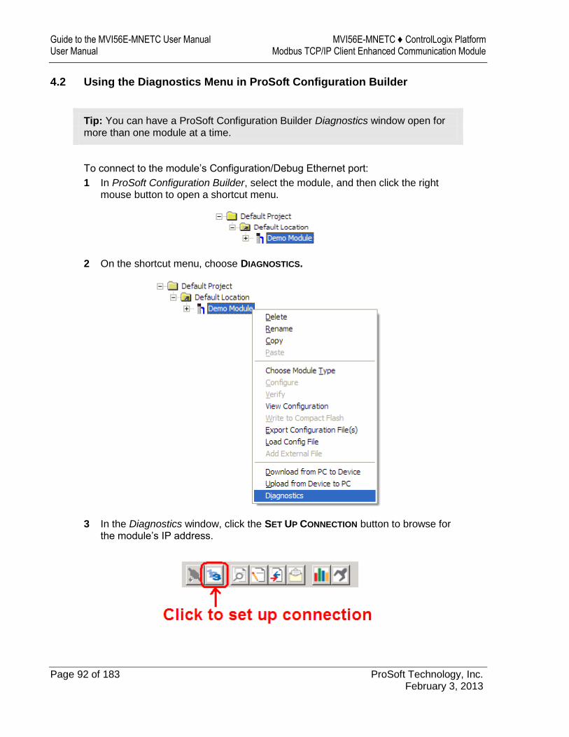
Guide to the MVI56E-MNETC User Manual MVI56E-MNETC ♦ ControlLogix Platform User Manual Modbus TCP/IP Client Enhanced Communication Module
Page 92 of 183 ProSoft Technology, Inc. February 3, 2013
4.2 Using the Diagnostics Menu in ProSoft Configuration Builder
Tip: You can have a ProSoft Configuration Builder Diagnostics window open for more than one module at a time.
To connect to the module’s Configuration/Debug Ethernet port:
1 In ProSoft Configuration Builder, select the module, and then click the right mouse button to open a shortcut menu.
2 On the shortcut menu, choose DIAGNOSTICS.
3 In the Diagnostics window, click the SET UP CONNECTION button to browse for the module’s IP address.
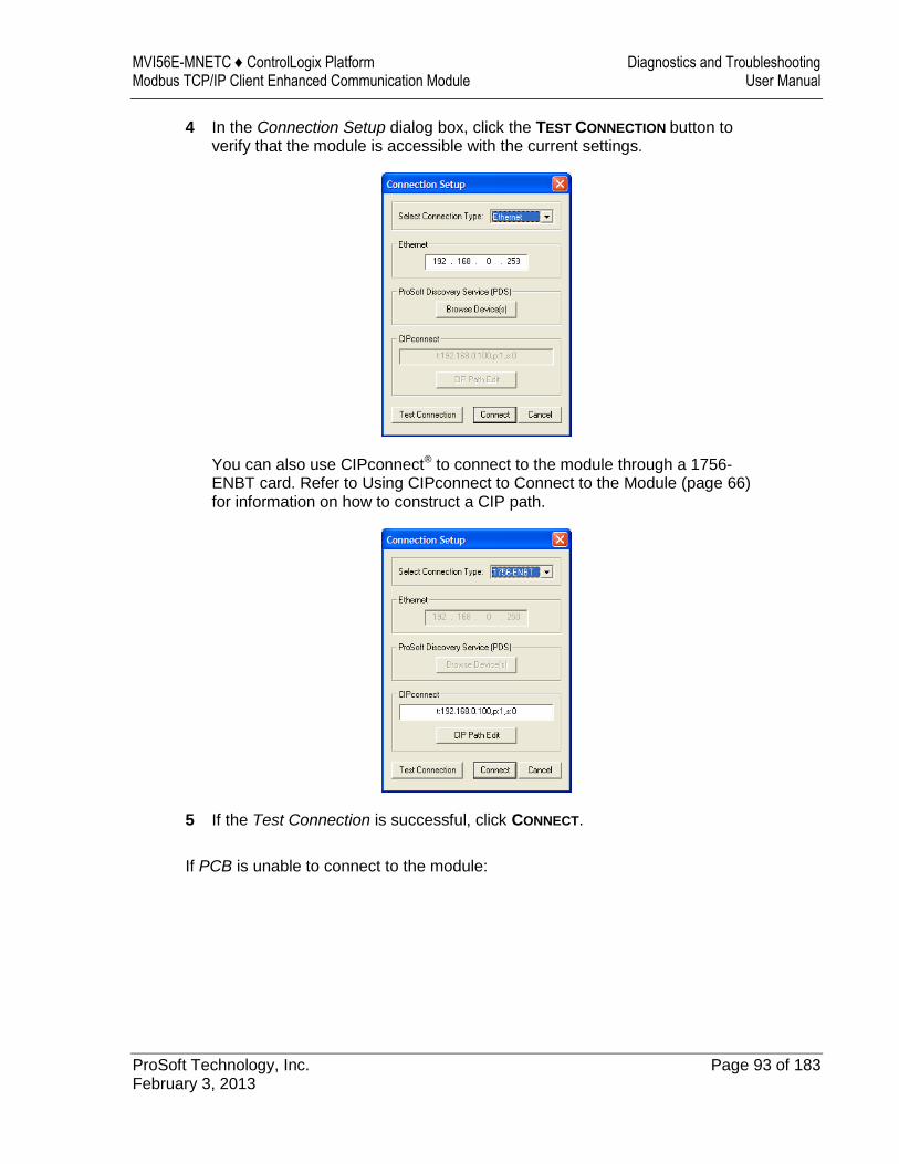
MVI56E-MNETC ♦ ControlLogix Platform Diagnostics and Troubleshooting Modbus TCP/IP Client Enhanced Communication Module User Manual
ProSoft Technology, Inc. Page 93 of 183 February 3, 2013
4 In the Connection Setup dialog box, click the TEST CONNECTION button to verify that the module is accessible with the current settings.
You can also use CIPconnect® to connect to the module through a 1756-ENBT card. Refer to Using CIPconnect to Connect to the Module (page 66) for information on how to construct a CIP path.
5 If the Test Connection is successful, click CONNECT.
If PCB is unable to connect to the module:
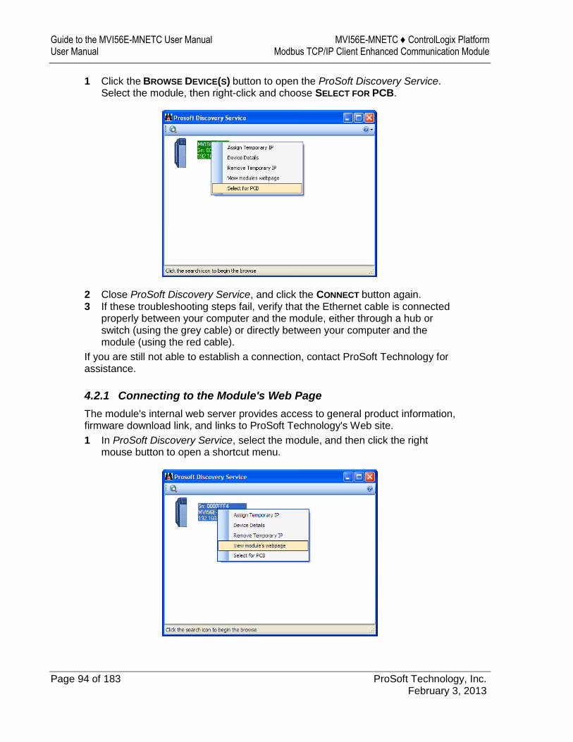
Guide to the MVI56E-MNETC User Manual MVI56E-MNETC ♦ ControlLogix Platform User Manual Modbus TCP/IP Client Enhanced Communication Module
Page 94 of 183 ProSoft Technology, Inc. February 3, 2013
1 Click the BROWSE DEVICE(S) button to open the ProSoft Discovery Service. Select the module, then right-click and choose SELECT FOR PCB.
2 Close ProSoft Discovery Service, and click the CONNECT button again. 3 If these troubleshooting steps fail, verify that the Ethernet cable is connected
properly between your computer and the module, either through a hub or switch (using the grey cable) or directly between your computer and the module (using the red cable).
If you are still not able to establish a connection, contact ProSoft Technology for assistance.
4.2.1 Connecting to the Module's Web Page
The module's internal web server provides access to general product information, firmware download link, and links to ProSoft Technology's Web site.
1 In ProSoft Discovery Service, select the module, and then click the right mouse button to open a shortcut menu.
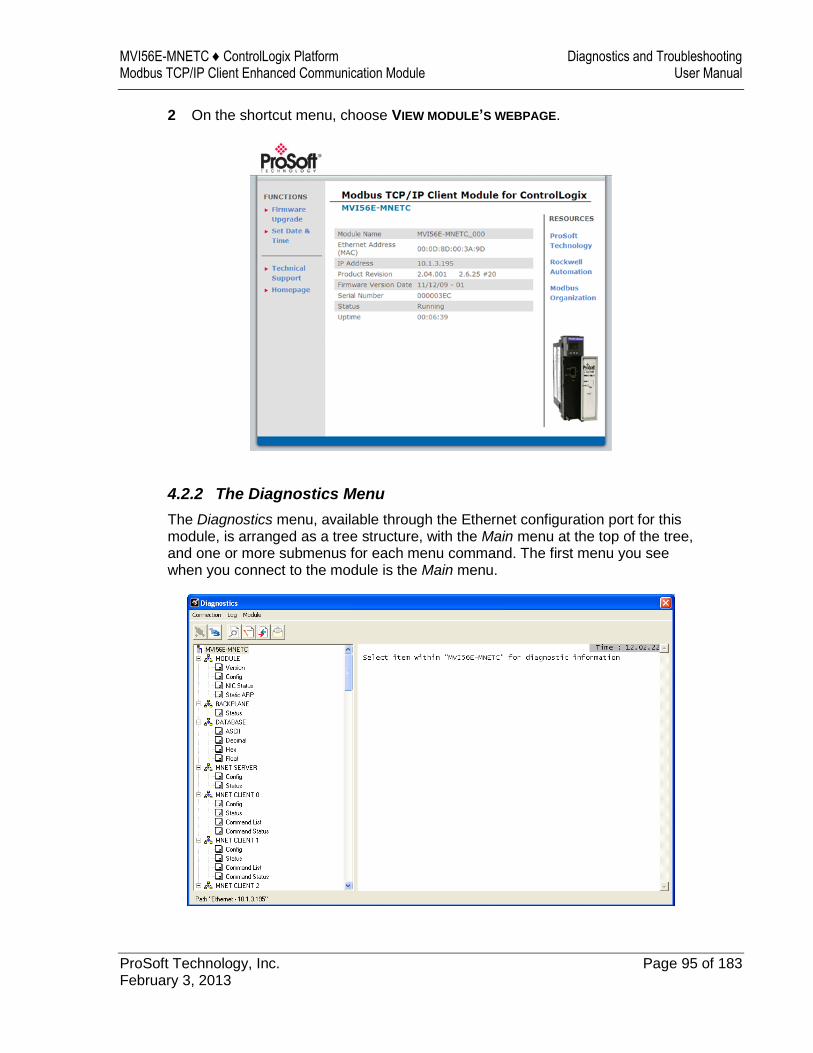
MVI56E-MNETC ♦ ControlLogix Platform Diagnostics and Troubleshooting Modbus TCP/IP Client Enhanced Communication Module User Manual
ProSoft Technology, Inc. Page 95 of 183 February 3, 2013
2 On the shortcut menu, choose VIEW MODULE’S WEBPAGE.
4.2.2 The Diagnostics Menu
The Diagnostics menu, available through the Ethernet configuration port for this module, is arranged as a tree structure, with the Main menu at the top of the tree, and one or more submenus for each menu command. The first menu you see when you connect to the module is the Main menu.
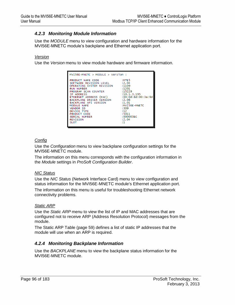
Guide to the MVI56E-MNETC User Manual MVI56E-MNETC ♦ ControlLogix Platform User Manual Modbus TCP/IP Client Enhanced Communication Module
Page 96 of 183 ProSoft Technology, Inc. February 3, 2013
4.2.3 Monitoring Module Information
Use the MODULE menu to view configuration and hardware information for the MVI56E-MNETC module’s backplane and Ethernet application port.
Version
Use the Version menu to view module hardware and firmware information.
Config
Use the Configuration menu to view backplane configuration settings for the MVI56E-MNETC module.
The information on this menu corresponds with the configuration information in the Module settings in ProSoft Configuration Builder.
NIC Status
Use the NIC Status (Network Interface Card) menu to view configuration and status information for the MVI56E-MNETC module's Ethernet application port.
The information on this menu is useful for troubleshooting Ethernet network connectivity problems.
Static ARP
Use the Static ARP menu to view the list of IP and MAC addresses that are configured not to receive ARP (Address Resolution Protocol) messages from the module.
The Static ARP Table (page 59) defines a list of static IP addresses that the module will use when an ARP is required.
4.2.4 Monitoring Backplane Information
Use the BACKPLANE menu to view the backplane status information for the MVI56E-MNETC module.

MVI56E-MNETC ♦ ControlLogix Platform Diagnostics and Troubleshooting Modbus TCP/IP Client Enhanced Communication Module User Manual
ProSoft Technology, Inc. Page 97 of 183 February 3, 2013
Backplane Status
Use the Status menu to view current backplane status, including
Number of retries Backplane status Fail count Number of words read Number of words written Number of words parsed Error count Event count Command count
During normal operation, the read, write, and parsing values should increment continuously, while the error value should not increment.
The status values on this menu correspond with members of the Status Data Definition (page 102).
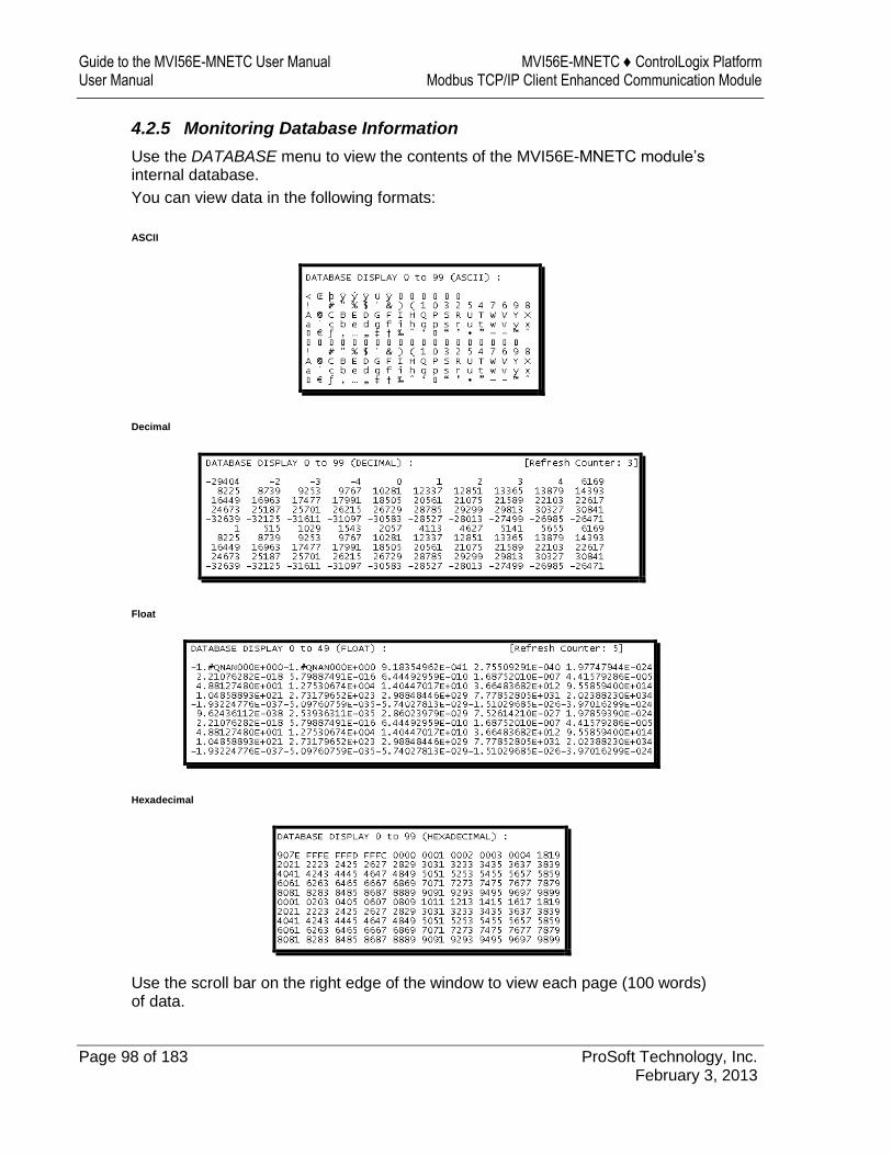
Guide to the MVI56E-MNETC User Manual MVI56E-MNETC ♦ ControlLogix Platform User Manual Modbus TCP/IP Client Enhanced Communication Module
Page 98 of 183 ProSoft Technology, Inc. February 3, 2013
4.2.5 Monitoring Database Information
Use the DATABASE menu to view the contents of the MVI56E-MNETC module’s internal database.
You can view data in the following formats:
ASCII
Decimal
Float
Hexadecimal
Use the scroll bar on the right edge of the window to view each page (100 words) of data.
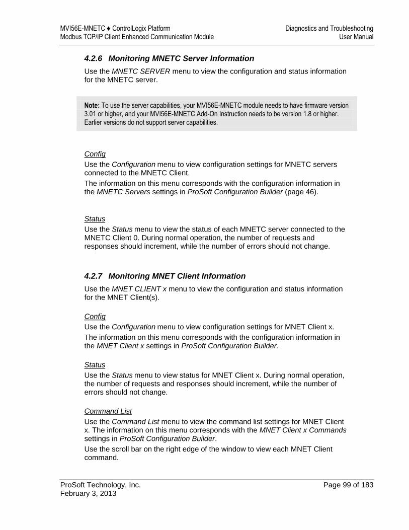
MVI56E-MNETC ♦ ControlLogix Platform Diagnostics and Troubleshooting Modbus TCP/IP Client Enhanced Communication Module User Manual
ProSoft Technology, Inc. Page 99 of 183 February 3, 2013
4.2.6 Monitoring MNETC Server Information
Use the MNETC SERVER menu to view the configuration and status information for the MNETC server.
Note: To use the server capabilities, your MVI56E-MNETC module needs to have firmware version 3.01 or higher, and your MVI56E-MNETC Add-On Instruction needs to be version 1.8 or higher. Earlier versions do not support server capabilities.
Config
Use the Configuration menu to view configuration settings for MNETC servers connected to the MNETC Client.
The information on this menu corresponds with the configuration information in the MNETC Servers settings in ProSoft Configuration Builder (page 46).
Status
Use the Status menu to view the status of each MNETC server connected to the MNETC Client 0. During normal operation, the number of requests and responses should increment, while the number of errors should not change.
4.2.7 Monitoring MNET Client Information
Use the MNET CLIENT x menu to view the configuration and status information for the MNET Client(s).
Config
Use the Configuration menu to view configuration settings for MNET Client x.
The information on this menu corresponds with the configuration information in the MNET Client x settings in ProSoft Configuration Builder.
Status
Use the Status menu to view status for MNET Client x. During normal operation, the number of requests and responses should increment, while the number of errors should not change.
Command List
Use the Command List menu to view the command list settings for MNET Client x. The information on this menu corresponds with the MNET Client x Commands settings in ProSoft Configuration Builder.
Use the scroll bar on the right edge of the window to view each MNET Client command.

Guide to the MVI56E-MNETC User Manual MVI56E-MNETC ♦ ControlLogix Platform User Manual Modbus TCP/IP Client Enhanced Communication Module
Page 100 of 183 ProSoft Technology, Inc. February 3, 2013
Command Status
Use the Command Status menu to view MNET Client x Command status.
A zero indicates no error.
A non-zero value indicates an error. For an explanation of each value, refer to Client Command Error (page 106).
MVI56E-MNETC ♦ ControlLogix Platform Diagnostics and Troubleshooting Modbus TCP/IP Client Enhanced Communication Module User Manual
ProSoft Technology, Inc. Page 101 of 183 February 3, 2013
4.3 Reading Status Data from the Module
Module status information is useful for troubleshooting and can be accessed in several different ways.
In the ladder logic's MNETC.STATUS controller tag structure.
The MVI56E-MNETC module returns status data in the input image that can be used to determine the module’s operating status. This data is transferred from the module to the ControlLogix processor continuously as part of the normal data transfer block sequence (page 114). You can view this data in the MNETC.STATUS controller tag structure in the ladder logic.
Client status data can also be requested and returned in a special Client Status block (page 122), outside of the normal data transfer block sequence. The status data contained in the Client Status block is different from the status data in the normal data transfer blocks. It can also be viewed in the MNETC.STATUS controller tag structure.
For more information about status data in MNETC.STATUS, see the Status Data Definition (page 102).
In ProSoft Configuration Builder's Diagnostics screens.
For more information, see the section on PCB Diagnostics (page 95).
In database locations specified by Error/Status Pointers (optional).
If optional Error/Status Pointers are enabled, status data can also be found in the Read Data area of the module’s database at the locations specified by the pointer configuration parameters. For more information, see Backplane Error/Status Pointer (page 43), Client Error/Status Pointer (page 49) and Command Error Pointer (page 49).
Guide to the MVI56E-MNETC User Manual MVI56E-MNETC ♦ ControlLogix Platform User Manual Modbus TCP/IP Client Enhanced Communication Module
Page 102 of 183 ProSoft Technology, Inc. February 3, 2013
4.3.1 Status Data Definition
This section contains a description of the controller tags in the MNETC.STATUS controller tag structure, which contains module and Client status data.
The first ten controller tags contain status data routinely transferred from the module to the processor in the normal data transfer block sequence (page 114).
The next controller tags are used to request and receive Client status data via the Client Status block functionality (page 122).
The next controller tags are the Event Sequence tags (blocks 4000 4100, and 4200), described on pages Error! Bookmark not defined. through Error! Bookmark not defined..
The remaining controller tags are used to request and receive server status data via the Server Status block functionality (page 123).
Note: In order to access up-to-date status data from these remaining controller tags, you must ensure that a Client Status block or Server Status block was recently received from the module. Client Status blocks and Server Status blocks are not routinely sent from the module; they are returned on a once-per-request basis as a response to a Client Status block request or Server Status block request from the processor.
Note: To use the server capabilities, your MVI56E-MNETC module needs to have firmware version 3.01 or higher, and your MVI56E-MNETC Add-On Instruction needs to be version 1.8 or higher. Earlier versions do not support server capabilities.

MVI56E-MNETC ♦ ControlLogix Platform Diagnostics and Troubleshooting Modbus TCP/IP Client Enhanced Communication Module User Manual
ProSoft Technology, Inc. Page 103 of 183 February 3, 2013
Controller Tag Data Type Description
PassCnt INT This value is incremented each time a complete program cycle occurs in the module.
ProductVersion INT Product version
ProductCode INT[2] Product code
BlockStats.Read INT Total number of read blocks transferred from the module to the processor
BlockStats.Write INT Total number of write blocks transferred from the processor to the module
BlockStats.Parse INT Total number of blocks successfully parsed that were received from the processor
BlockStats.Event INT Total number of Event Command blocks received from the processor
BlockStats.Cmd INT Total number of Command Control blocks received from the processor
BlockStats.Err INT Total number of block errors recognized by the module
CmdBits[x] INT Displays enabled or disabled status of all 16 commands in the Client x Command List for each Client
ClientStatsTrigger BOOL Initiates request for Client Status block from module when set to 1
ClientID INT Specifies Client (0-29) to request status data from
ClientStatus[x].CmdReq INT Total number of command list requests sent from Client
ClientStatus[x].CmdResp INT Total number of command list responses received by Client
ClientStatus[x].CmdErr INT This value is incremented each time an error message is received from a remote unit or a local error is generated for a command.
ClientStatus[x].Requests INT Not used
ClientStatus[x].Responses INT Not used
ClientStatus[x].ErrSent INT Not used
ClientStatus[x].ErrRec INT Not used
ClientStatus[x].CfgErrWord INT Configuration Error Word - This word contains a bitmap that indicates general module configuration errors.
ClientStatus[x].CurErr INT Most recent error code recorded for the Client
ClientStatus[x].LastErr INT Previous most recent error code recorded for the Client
CmdErrorList[x] INT Command error code for each command (0-15) on the specified Client's command list
EventSeqCmdPending.Trigger
BOOL Set to 1 to trigger the command queue status data
request.
EventSeqCmdPending.Client[x]_QueueCount
SINT Number of Event sequence commands for which status has not yet been retrieved
EventSeqCmdPending.Client[x]_WaitingMsgs
SINT Total number of commands waiting in the command queue
EventSeqCmd.Trigger BOOL Set the value of this tag to 1 to trigger the Event
Sequence Command block request.
EventSeqCmd.ClientID INT Specifies Client (0-29) to request status data from.

Guide to the MVI56E-MNETC User Manual MVI56E-MNETC ♦ ControlLogix Platform User Manual Modbus TCP/IP Client Enhanced Communication Module
Page 104 of 183 ProSoft Technology, Inc. February 3, 2013
Controller Tag Data Type Description
EventSeqCmd.Client[x].Count
INT Number of Event Sequence Commands executed by the specified Client for which status has not yet been retrieved
EventSeqCmd.Client[x].Cmd[x].Sequence
INT Sequence number for each Event Sequence command
EventSeqCmd.Client[x].Cmd[x].Error
INT Error code for each Event Sequence command: 0=success, 1=failure
EventSeqReady DINT One bit for each Client, indicating which Clients have Event Sequence commands with unretrieved status data: 0=no status data available, 1=status data available for retrieval
ServerStatusTrigger BOOL Set to 1 to trigger the Server Status block request.
ServerStatus.MNET.Requests
INT This counter increments each time an MNet (port 2000) request is received.
ServerStatus.MNET.Responses
INT This counter increments each time an MNet (port 2000) response message is sent.
ServerStatus.MNET.ErrSent INT This counter increments each time an MNet (port 2000) sends an exception response to Client. Example: Client sent illegal Modbus Data location address.
ServerStatus.MNET.ErrRec INT This counter increments each time an MNet (port 2000) receives a bad command. Example: Client sent illegal function command.
ServerStatus.MBAP.Requests
INT This counter increments each time an MBAP (port 502) request is received.
ServerStatus.MBAP.Responses
INT This counter increments each time an MBAP (port 502) response message is sent.
ServerStatus.MBAP.ErrSent INT This counter increments each time an MBAP (port 502) sends an exception response to Client. Example: Client sent illegal Modbus Data location address.
ServerStatus.MBAP.ErrRec INT This counter increments each time an MBAP (port 502) receives a bad command. Example: Client sent illegal function command.
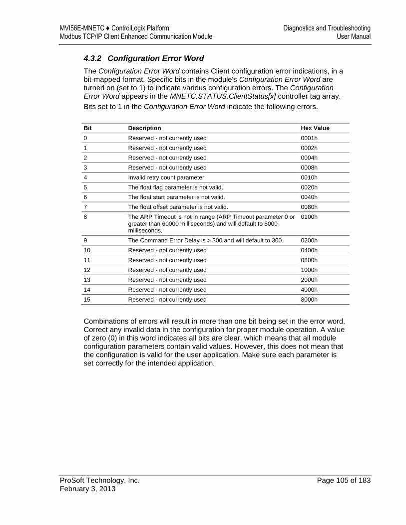
MVI56E-MNETC ♦ ControlLogix Platform Diagnostics and Troubleshooting Modbus TCP/IP Client Enhanced Communication Module User Manual
ProSoft Technology, Inc. Page 105 of 183 February 3, 2013
4.3.2 Configuration Error Word
The Configuration Error Word contains Client configuration error indications, in a bit-mapped format. Specific bits in the module's Configuration Error Word are turned on (set to 1) to indicate various configuration errors. The Configuration Error Word appears in the MNETC.STATUS.ClientStatus[x] controller tag array.
Bits set to 1 in the Configuration Error Word indicate the following errors.
Bit Description Hex Value
0 Reserved - not currently used 0001h
1 Reserved - not currently used 0002h
2 Reserved - not currently used 0004h
3 Reserved - not currently used 0008h
4 Invalid retry count parameter 0010h
5 The float flag parameter is not valid. 0020h
6 The float start parameter is not valid. 0040h
7 The float offset parameter is not valid. 0080h
8 The ARP Timeout is not in range (ARP Timeout parameter 0 or greater than 60000 milliseconds) and will default to 5000 milliseconds.
0100h
9 The Command Error Delay is > 300 and will default to 300. 0200h
10 Reserved - not currently used 0400h
11 Reserved - not currently used 0800h
12 Reserved - not currently used 1000h
13 Reserved - not currently used 2000h
14 Reserved - not currently used 4000h
15 Reserved - not currently used 8000h
Combinations of errors will result in more than one bit being set in the error word. Correct any invalid data in the configuration for proper module operation. A value of zero (0) in this word indicates all bits are clear, which means that all module configuration parameters contain valid values. However, this does not mean that the configuration is valid for the user application. Make sure each parameter is set correctly for the intended application.
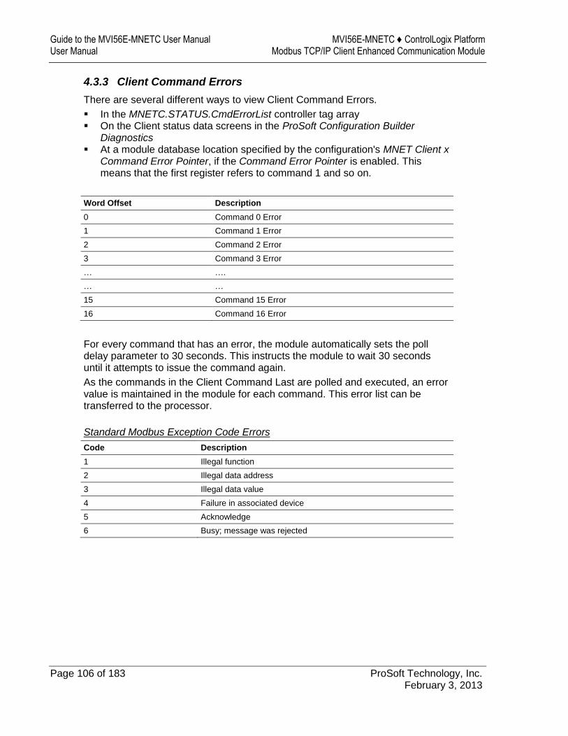
Guide to the MVI56E-MNETC User Manual MVI56E-MNETC ♦ ControlLogix Platform User Manual Modbus TCP/IP Client Enhanced Communication Module
Page 106 of 183 ProSoft Technology, Inc. February 3, 2013
4.3.3 Client Command Errors
There are several different ways to view Client Command Errors.
In the MNETC.STATUS.CmdErrorList controller tag array On the Client status data screens in the ProSoft Configuration Builder
Diagnostics At a module database location specified by the configuration's MNET Client x
Command Error Pointer, if the Command Error Pointer is enabled. This means that the first register refers to command 1 and so on.
Word Offset Description
0 Command 0 Error
1 Command 1 Error
2 Command 2 Error
3 Command 3 Error
… ….
… …
15 Command 15 Error
16 Command 16 Error
For every command that has an error, the module automatically sets the poll delay parameter to 30 seconds. This instructs the module to wait 30 seconds until it attempts to issue the command again.
As the commands in the Client Command Last are polled and executed, an error value is maintained in the module for each command. This error list can be transferred to the processor.
Standard Modbus Exception Code Errors
Code Description
1 Illegal function
2 Illegal data address
3 Illegal data value
4 Failure in associated device
5 Acknowledge
6 Busy; message was rejected
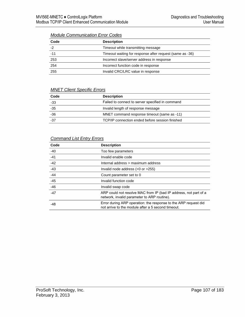
MVI56E-MNETC ♦ ControlLogix Platform Diagnostics and Troubleshooting Modbus TCP/IP Client Enhanced Communication Module User Manual
ProSoft Technology, Inc. Page 107 of 183 February 3, 2013
Module Communication Error Codes
Code Description
-2 Timeout while transmitting message
-11 Timeout waiting for response after request (same as -36)
253 Incorrect slave/server address in response
254 Incorrect function code in response
255 Invalid CRC/LRC value in response
MNET Client Specific Errors
Code Description
-35 Invalid length of response message
-36 MNET command response timeout (same as -11)
-37 TCP/IP connection ended before session finished
Command List Entry Errors
Code Description
-40 Too few parameters
-41 Invalid enable code
-42 Internal address > maximum address
-43 Invalid node address (<0 or >255)
-44 Count parameter set to 0
-45 Invalid function code
-46 Invalid swap code
-33
Failed to connect to server specified in command
-47 ARP could not resolve MAC from IP (bad IP address, not part of a network, invalid parameter to ARP routine).
-48 Error during ARP operation: the response to the ARP request did not arrive to the module after a 5 second timeout.

Guide to the MVI56E-MNETC User Manual MVI56E-MNETC ♦ ControlLogix Platform User Manual Modbus TCP/IP Client Enhanced Communication Module
Page 108 of 183 ProSoft Technology, Inc. February 3, 2013
MVI56E-MNETC ♦ ControlLogix Platform Reference Modbus TCP/IP Client Enhanced Communication Module User Manual
ProSoft Technology, Inc. Page 109 of 183 February 3, 2013
5 Reference
In This Chapter
Product Specifications ......................................................................... 110
Backplane Data Transfer ..................................................................... 112
Data Flow between MVI56E-MNETC Module and Processor ............. 138
Ethernet Cable Specifications ............................................................. 143
Modbus Protocol Specification ............................................................ 145
Using the Optional Add-On Instruction Rung Import ........................... 158
Adding the Module to an Existing Project ............................................ 169
Using the Sample Program ................................................................. 172

Guide to the MVI56E-MNETC User Manual MVI56E-MNETC ♦ ControlLogix Platform User Manual Modbus TCP/IP Client Enhanced Communication Module
Page 110 of 183 ProSoft Technology, Inc. February 3, 2013
5.1 Product Specifications
The MVI56E Modbus TCP/IP Client Enhanced Communication Module allows Rockwell Automation® ControlLogix® Programmable Automation Controllers (PACs) to interface easily with Modicon Programmable Automation Controller (PACs) , as well as multiple Modbus TCP/IP server-compatible instruments and devices. The multi-Client module improves performance when controlling multiple servers on a Modbus TCP/IP network, by supporting up to 30 Clients. It also supports up to 20 server connections (10 MNET, 10 MBAP).
MVI56E enhancements include configuration and management through the module’s Ethernet port, and CIPconnect® technology for bridging though ControlNet™ and EtherNet/IP™ networks.
5.1.1 General Specifications
Backward compatible with previous MVI56-MNETC versions Single-slot 1756 ControlLogix backplane compatible 10/100 Mbps auto crossover detection Ethernet configuration and application
port User-definable module data memory mapping of up to 10,000 16-bit registers CIPconnect-enabled network configuration and diagnostics monitoring using
ControlLogix 1756-ENxT and 1756-CNB modules and EtherNet/IP pass-through communication
ProSoft Configuration Builder (PCB) software supported, a Windows-based graphical user interface providing simple product and network configuration
Sample ladder logic and Add-On Instructions (AOI) are used for data transfer between module and processor
4-character, alpha-numeric, scrolling LED display of status and diagnostics data in plain English – no cryptic error or alarm codes to decipher
ProSoft Discovery Service (PDS) software used to locate the module on the network and assign temporary IP address
Personality Module - a non-volatile industrial-grade Compact Flash (CF) card used to store network and module configuration for easy disaster recovery, allowing quick in-the-field product replacement by transferring the CF card
5.1.2 Modbus TCP/IP Specifications
ProSoft Technology’s Modbus TCP/IP implementation (MNET) includes both Client (Master) and server (slave) capabilities.
Modbus TCP/IP Server (Slave)
Supports ten independent server connections for Service Port 502 (MBAP) Supports ten independent server connections for Service Port 2000
(Encapsulated) Accepts Modbus Function Codes 1, 2, 3, 4, 5, 6, 7, 8, 15, 16, 17, 22 and 23 Module data can be derived from other Modbus server devices on the
network through the Client or from the ControlLogix processor
MVI56E-MNETC ♦ ControlLogix Platform Reference Modbus TCP/IP Client Enhanced Communication Module User Manual
ProSoft Technology, Inc. Page 111 of 183 February 3, 2013
Modbus TCP/IP Client (Master)
Offers 30 Client connections with up to 16 commands each to talk to multiple servers
Actively reads data from and writes data to Modbus TCP/IP devices, using MBAP or Encapsulated Modbus message formats
Transmits Modbus Function Codes 1, 2, 3, 4, 5, 6, 7, 15, and 16 ControlLogix processor can be programmed to use special functions to
control the activity on the Client by actively selecting commands to execute from the command list (Command Control) or by issuing commands directly from the ladder logic (Event Commands)
5.1.3 Functional Specifications
Modbus data types overlap in the module's memory database, so the same data can be conveniently read or written as bit-level or register-level data.
Configurable floating-point data movement is supported, including support for Enron or Daniel® floating-point formats
Special functions (Event Commands, Command Control, status, etc.) are supported by message transfer (unscheduled) using the MSG instruction
Configurable parameters for the Client including a minimum response delay of 0 to 65535 ms and floating-point support
Supports up to 30 Clients with up to 16 commands for each Client Error codes, counters, and module status available from module memory
through the servers, through the Clients, or through the ladder logic and controller tags in RSLogix 5000
5.1.4 Hardware Specifications
Specification Description
Dimensions Standard 1756 ControlLogix® single-slot module
Backplane current load 800 mA @ 5 Vdc 3 mA @ 24 Vdc
Operating temperature 0°C to 60°C (32°F to 140°F)
Storage temperature -40°C to 85°C (-40°F to 185°F)
Shock 30 g operational 50 g non-operational
Vibration 5 g from 10 Hz to 150 Hz
Relative humidity 5% to 95% (with no condensation)
LED indicators Battery Status (ERR) Application Status (APP) Module Status (OK)
4-character, scrolling, alphanumeric LED display
Shows module, version, IP, application port setting, port status, and error information
Ethernet port 10/100 Base-T, RJ45 Connector, for CAT5 cable
Link and Activity LED indicators
Auto-crossover cable detection
Cable 5-foot Ethernet straight-through cable (shipped with unit)
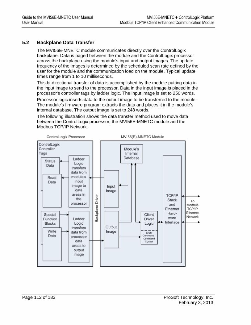
Guide to the MVI56E-MNETC User Manual MVI56E-MNETC ♦ ControlLogix Platform User Manual Modbus TCP/IP Client Enhanced Communication Module
Page 112 of 183 ProSoft Technology, Inc. February 3, 2013
5.2 Backplane Data Transfer
The MVI56E-MNETC module communicates directly over the ControlLogix backplane. Data is paged between the module and the ControlLogix processor across the backplane using the module's input and output images. The update frequency of the images is determined by the scheduled scan rate defined by the user for the module and the communication load on the module. Typical update times range from 1 to 10 milliseconds.
This bi-directional transfer of data is accomplished by the module putting data in the input image to send to the processor. Data in the input image is placed in the processor's controller tags by ladder logic. The input image is set to 250 words.
Processor logic inserts data to the output image to be transferred to the module. The module's firmware program extracts the data and places it in the module's internal database. The output image is set to 248 words.
The following illustration shows the data transfer method used to move data between the ControlLogix processor, the MVI56E-MNETC module and the Modbus TCP/IP Network.
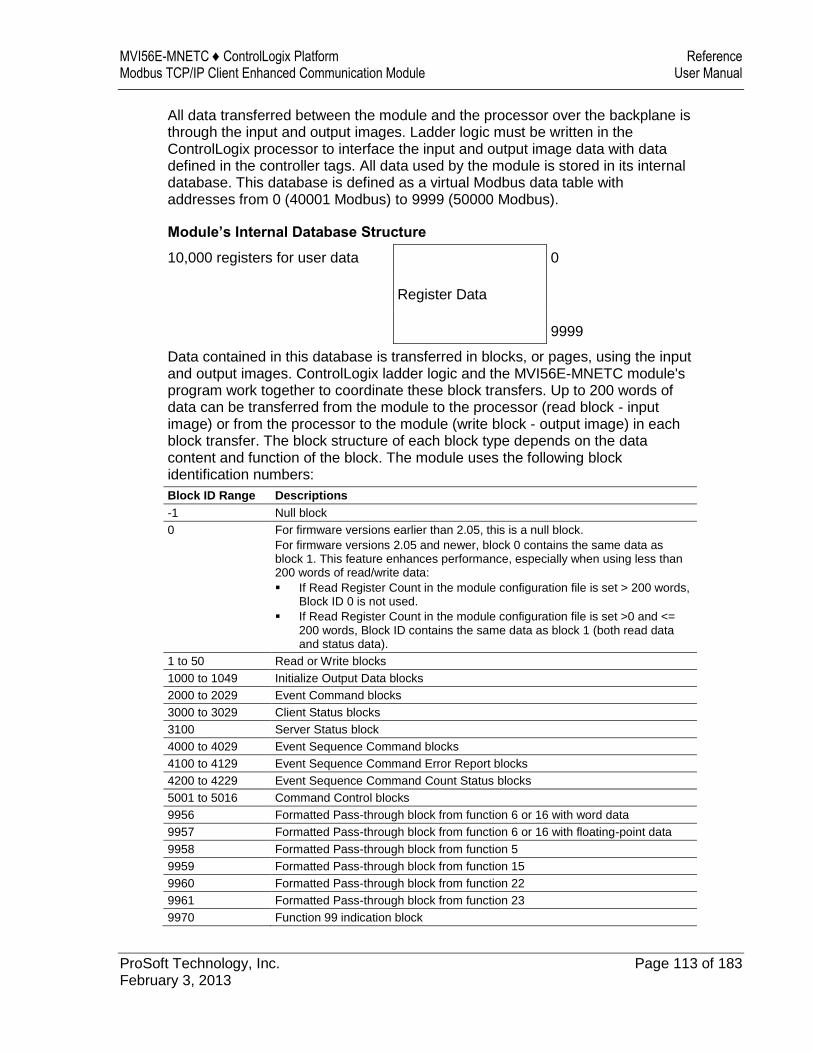
MVI56E-MNETC ♦ ControlLogix Platform Reference Modbus TCP/IP Client Enhanced Communication Module User Manual
ProSoft Technology, Inc. Page 113 of 183 February 3, 2013
All data transferred between the module and the processor over the backplane is through the input and output images. Ladder logic must be written in the ControlLogix processor to interface the input and output image data with data defined in the controller tags. All data used by the module is stored in its internal database. This database is defined as a virtual Modbus data table with addresses from 0 (40001 Modbus) to 9999 (50000 Modbus).
Module’s Internal Database Structure
10,000 registers for user data 0
Register Data
9999
Data contained in this database is transferred in blocks, or pages, using the input and output images. ControlLogix ladder logic and the MVI56E-MNETC module's program work together to coordinate these block transfers. Up to 200 words of data can be transferred from the module to the processor (read block - input image) or from the processor to the module (write block - output image) in each block transfer. The block structure of each block type depends on the data content and function of the block. The module uses the following block identification numbers:
Block ID Range Descriptions
-1 Null block
0 For firmware versions earlier than 2.05, this is a null block.
For firmware versions 2.05 and newer, block 0 contains the same data as block 1. This feature enhances performance, especially when using less than 200 words of read/write data:
If Read Register Count in the module configuration file is set > 200 words, Block ID 0 is not used.
If Read Register Count in the module configuration file is set >0 and <= 200 words, Block ID contains the same data as block 1 (both read data and status data).
1 to 50 Read or Write blocks
1000 to 1049 Initialize Output Data blocks
2000 to 2029 Event Command blocks
3000 to 3029 Client Status blocks
3100 Server Status block
4000 to 4029 Event Sequence Command blocks
4100 to 4129 Event Sequence Command Error Report blocks
4200 to 4229 Event Sequence Command Count Status blocks
5001 to 5016 Command Control blocks
9956 Formatted Pass-through block from function 6 or 16 with word data
9957 Formatted Pass-through block from function 6 or 16 with floating-point data
9958 Formatted Pass-through block from function 5
9959 Formatted Pass-through block from function 15
9960 Formatted Pass-through block from function 22
9961 Formatted Pass-through block from function 23
9970 Function 99 indication block
Guide to the MVI56E-MNETC User Manual MVI56E-MNETC ♦ ControlLogix Platform User Manual Modbus TCP/IP Client Enhanced Communication Module
Page 114 of 183 ProSoft Technology, Inc. February 3, 2013
Block ID Range Descriptions
9990 Set Module IP Address block
9991 Get Module IP Address block
9996 Unformatted Pass-through block with raw Modbus message
9997 Reset Module Status Data block
9998 Warm-boot block
9999 Cold-boot block
These block identification codes can be broken down into two groups:
Normal data transfer blocks
Read and Write blocks (-1 to 50)
Special function blocks
Initialize Output Data blocks (1000 to 1049) Event Command blocks (2000 to 2029) Client Status blocks (3000 to 3029) Server Status block (3100) Event Sequence Command blocks (4000 to 4029) Event Sequence Command Status blocks (4100 to 4129 and 4200) Command Control blocks (5001 to 5016) Pass-through Request blocks (9956 to 9961, 9970, and 9996) Module IP Address blocks (9990 and 9991) Reset Module Status block (9997) Warm-boot and Cold-boot blocks (9998 and 9999)
5.2.1 Normal Data Transfer Blocks
Normal data transfer includes the paging of user data from the module’s internal database (registers 0 to 9999), as well as paging of status data. These data are transferred through read (input image) and write (output image) blocks.
The following topics describe the function and structure of each block.
Read Block
These blocks of data transfer information from the module to the ControlLogix processor.
The following table describes the structure of the input image.
Read Block from Module to Processor
Word Offset Description Length
0 Reserved 1
1 Write Block ID: -1 to 50 1
2 to 201 Read Data 200
202 Program Scan Counter 1
203 to 208 Block Transfer Status 6
209 to 238 Command bit data for Clients 30
239 to 240 Product Code 2
MVI56E-MNETC ♦ ControlLogix Platform Reference Modbus TCP/IP Client Enhanced Communication Module User Manual
ProSoft Technology, Inc. Page 115 of 183 February 3, 2013
Word Offset Description Length
241 Product Version 1
242 to 248 Reserved 7
249 Read Block ID 1
The Read Block ID is an index value used to determine where the 200 words of data from module memory will be placed in the ReadData[x] controller tag array of the ControlLogix processor. Each transfer can move up to 200 words (block offsets 2 to 201) of data. In addition to moving user data, the block also contains status data for the module. The Write Block ID associated with the block requests data from the ControlLogix processor.
During normal program operation, the module sequentially sends read blocks and requests write blocks.
For example, if the application uses three read and two write blocks, the sequence will be as follows:
R1W1R2W2R3W1R1W2R2W1R3W2R1W1
This sequence will continue until interrupted by other write block numbers sent by the controller or by a command request from a node on the Modbus network or operator control through the module’s Configuration/Debug port.
Status Data in Read Block
The following table describes in more detail the status information found in the Read Block.
Word Offset Content Description
202 Program Scan Count This value is incremented each time a complete program cycle occurs in the module.
203 Read Block Count This field contains the total number of read blocks transferred from the module to the processor.
204 Write Block Count This field contains the total number of write blocks transferred from the processor to the module.
205 Parse Block Count This field contains the total number of blocks successfully parsed that were received from the processor.
206 Command Event Block Count
This field contains the total number of command event blocks received from the processor.
207 Command Block Count This field contains the total number of command blocks received from the processor.
208 Error Block Count This field contains the total number of block errors recognized by the module.
209 Client 0 command execution word
Each bit in this word enables/disable the commands for Client 0. If the bit is set, the command will execute. If the bit is clear, the command will be disabled. This data is set in the output image (WriteBlock) from the ladder logic.
Guide to the MVI56E-MNETC User Manual MVI56E-MNETC ♦ ControlLogix Platform User Manual Modbus TCP/IP Client Enhanced Communication Module
Page 116 of 183 ProSoft Technology, Inc. February 3, 2013
Word Offset Content Description
210 to 238 Client 1 to Client 29 command execution words
These 29 words are used for each of the other 29 Clients in the module. This data is set in the output image (WriteBlock) from the ladder logic.
239 to 240 Product Code The product ID code for the module
241 Product Version The firmware version number for the module
Status information transferred in the Read block can be viewed in the MNETC.STATUS controller tag in the ladder logic. For more information, see the Status Data Definition (page 102).
Write Block
These blocks of data transfer information from the ControlLogix processor to the module.
The following table describes the structure of the output image.
Write Block from Processor to Module
Word Offset Description Length
0 Write Block ID: -1 to 50 1
1 to 200 Write Data 200
201 to 230 Command bit data for Clients (set) 30
231 to 246 Spare 16
247 Select Priority Read 1
The Write Block ID is an index value used to determine the location in the module’s database where the data will be placed. Each transfer can move up to 200 words (block offsets 1 to 200) of data.
Select Priority Read Block (Write Block Offset 247)
Note: The Select Priority Read Block feature is only available for firmware versions 1.36.000 and newer.
This register allows the processor to select which read blocks will be returned from the module. If this register equals zero, the module will return all read blocks in sequential order.
If this register has a non-zero value, the module will return the read block selected, and the following one.
This feature can be used for applications that require some read blocks to be updated more frequently than other blocks.
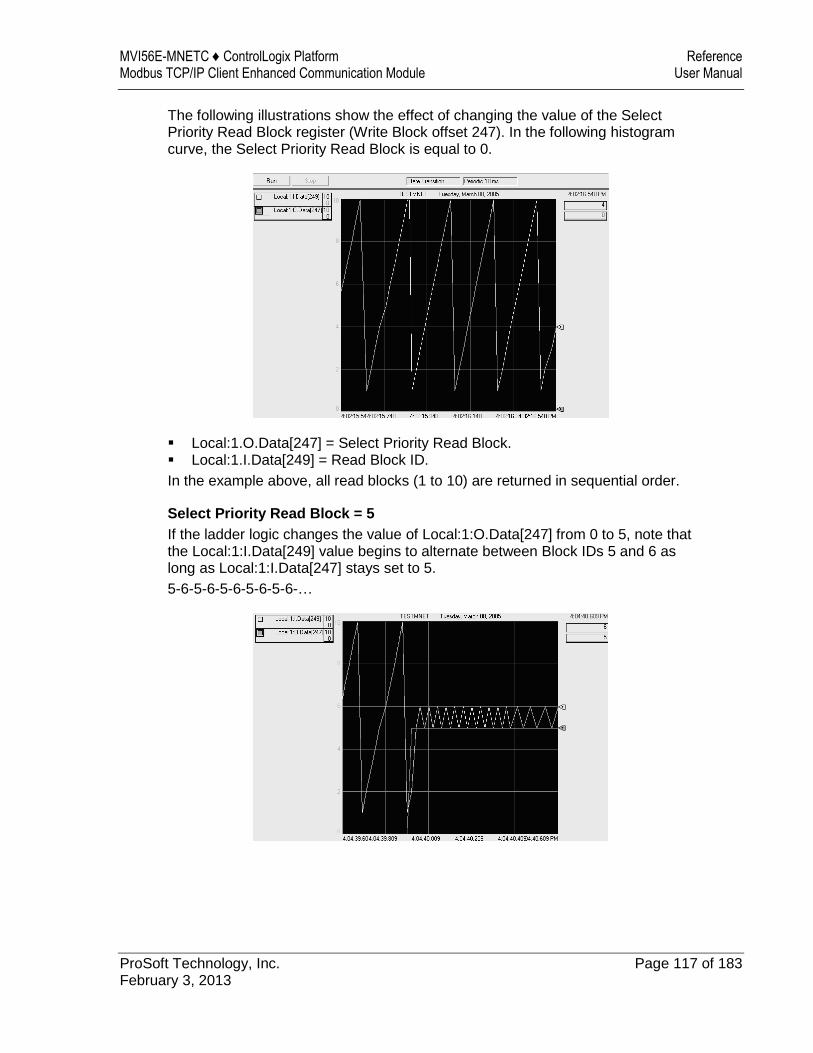
MVI56E-MNETC ♦ ControlLogix Platform Reference Modbus TCP/IP Client Enhanced Communication Module User Manual
ProSoft Technology, Inc. Page 117 of 183 February 3, 2013
The following illustrations show the effect of changing the value of the Select Priority Read Block register (Write Block offset 247). In the following histogram curve, the Select Priority Read Block is equal to 0.
Local:1.O.Data[247] = Select Priority Read Block. Local:1.I.Data[249] = Read Block ID.
In the example above, all read blocks (1 to 10) are returned in sequential order.
Select Priority Read Block = 5
If the ladder logic changes the value of Local:1:O.Data[247] from 0 to 5, note that the Local:1:I.Data[249] value begins to alternate between Block IDs 5 and 6 as long as Local:1:I.Data[247] stays set to 5.
5-6-5-6-5-6-5-6-5-6-…
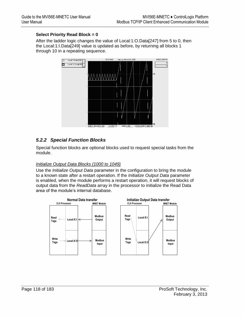
Guide to the MVI56E-MNETC User Manual MVI56E-MNETC ♦ ControlLogix Platform User Manual Modbus TCP/IP Client Enhanced Communication Module
Page 118 of 183 ProSoft Technology, Inc. February 3, 2013
Select Priority Read Block = 0
After the ladder logic changes the value of Local:1:O.Data[247] from 5 to 0, then the Local:1:I.Data[249] value is updated as before, by returning all blocks 1 through 10 in a repeating sequence.
5.2.2 Special Function Blocks
Special function blocks are optional blocks used to request special tasks from the module.
Initialize Output Data Blocks (1000 to 1049)
Use the Initialize Output Data parameter in the configuration to bring the module to a known state after a restart operation. If the Initialize Output Data parameter is enabled, when the module performs a restart operation, it will request blocks of output data from the ReadData array in the processor to initialize the Read Data area of the module’s internal database.
CLX Processor
Read
TagsLocal:X:I
Local:X:O
MNET Module
Normal Data transfer
Modbus
Output
Modbus
Input
Write
Tags
CLX Processor
Read
TagsLocal:X:I
Local:X:O
MNET Module
Initialize Output Data transfer
Modbus
Output
Modbus
Input
Write
Tags
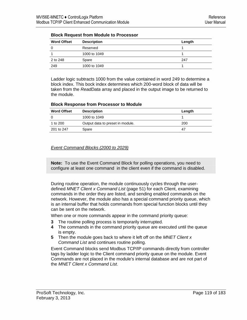
MVI56E-MNETC ♦ ControlLogix Platform Reference Modbus TCP/IP Client Enhanced Communication Module User Manual
ProSoft Technology, Inc. Page 119 of 183 February 3, 2013
Block Request from Module to Processor
Word Offset Description Length
0 Reserved 1
1 1000 to 1049 1
2 to 248 Spare 247
249 1000 to 1049 1
Ladder logic subtracts 1000 from the value contained in word 249 to determine a block index. This bock index determines which 200-word block of data will be taken from the ReadData array and placed in the output image to be returned to the module.
Block Response from Processor to Module
Word Offset Description Length
0 1000 to 1049 1
1 to 200 Output data to preset in module. 200
201 to 247 Spare 47
Event Command Blocks (2000 to 2029)
Note: To use the Event Command Block for polling operations, you need to configure at least one command in the client even if the command is disabled.
During routine operation, the module continuously cycles through the user-defined MNET Client x Command List (page 51) for each Client, examining commands in the order they are listed, and sending enabled commands on the network. However, the module also has a special command priority queue, which is an internal buffer that holds commands from special function blocks until they can be sent on the network.
When one or more commands appear in the command priority queue:
3 The routine polling process is temporarily interrupted. 4 The commands in the command priority queue are executed until the queue
is empty. 5 Then the module goes back to where it left off on the MNET Client x
Command List and continues routine polling.
Event Command blocks send Modbus TCP/IP commands directly from controller tags by ladder logic to the Client command priority queue on the module. Event Commands are not placed in the module's internal database and are not part of the MNET Client x Command List.
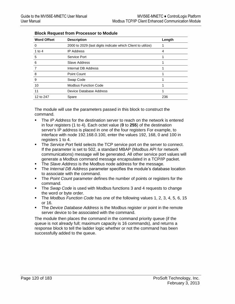
Guide to the MVI56E-MNETC User Manual MVI56E-MNETC ♦ ControlLogix Platform User Manual Modbus TCP/IP Client Enhanced Communication Module
Page 120 of 183 ProSoft Technology, Inc. February 3, 2013
Block Request from Processor to Module
Word Offset Description Length
0 2000 to 2029 (last digits indicate which Client to utilize) 1
1 to 4 IP Address 4
5 Service Port 1
6 Slave Address 1
7 Internal DB Address 1
8 Point Count 1
9 Swap Code 1
10 Modbus Function Code 1
11 Device Database Address 1
12 to 247 Spare 236
The module will use the parameters passed in this block to construct the command.
The IP Address for the destination server to reach on the network is entered in four registers (1 to 4). Each octet value (0 to 255) of the destination server's IP address is placed in one of the four registers For example, to interface with node 192.168.0.100, enter the values 192, 168, 0 and 100 in registers 1 to 4.
The Service Port field selects the TCP service port on the server to connect. If the parameter is set to 502, a standard MBAP (Modbus API for network communications) message will be generated. All other service port values will generate a Modbus command message encapsulated in a TCP/IP packet.
The Slave Address is the Modbus node address for the message. The Internal DB Address parameter specifies the module’s database location
to associate with the command. The Point Count parameter defines the number of points or registers for the
command. The Swap Code is used with Modbus functions 3 and 4 requests to change
the word or byte order. The Modbus Function Code has one of the following values 1, 2, 3, 4, 5, 6, 15
or 16. The Device Database Address is the Modbus register or point in the remote
server device to be associated with the command.
The module then places the command in the command priority queue (if the queue is not already full; maximum capacity is 16 commands), and returns a response block to tell the ladder logic whether or not the command has been successfully added to the queue.
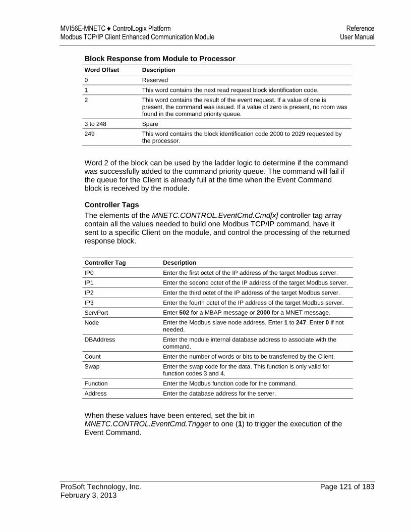
MVI56E-MNETC ♦ ControlLogix Platform Reference Modbus TCP/IP Client Enhanced Communication Module User Manual
ProSoft Technology, Inc. Page 121 of 183 February 3, 2013
Block Response from Module to Processor
Word Offset Description
0 Reserved
1 This word contains the next read request block identification code.
2 This word contains the result of the event request. If a value of one is present, the command was issued. If a value of zero is present, no room was found in the command priority queue.
3 to 248 Spare
249 This word contains the block identification code 2000 to 2029 requested by the processor.
Word 2 of the block can be used by the ladder logic to determine if the command was successfully added to the command priority queue. The command will fail if the queue for the Client is already full at the time when the Event Command block is received by the module.
Controller Tags
The elements of the MNETC.CONTROL.EventCmd.Cmd[x] controller tag array contain all the values needed to build one Modbus TCP/IP command, have it sent to a specific Client on the module, and control the processing of the returned response block.
Controller Tag Description
IP0 Enter the first octet of the IP address of the target Modbus server.
IP1 Enter the second octet of the IP address of the target Modbus server.
IP2 Enter the third octet of the IP address of the target Modbus server.
IP3 Enter the fourth octet of the IP address of the target Modbus server.
ServPort Enter 502 for a MBAP message or 2000 for a MNET message.
Node Enter the Modbus slave node address. Enter 1 to 247. Enter 0 if not
needed.
DBAddress Enter the module internal database address to associate with the command.
Count Enter the number of words or bits to be transferred by the Client.
Swap Enter the swap code for the data. This function is only valid for function codes 3 and 4.
Function Enter the Modbus function code for the command.
Address Enter the database address for the server.
When these values have been entered, set the bit in MNETC.CONTROL.EventCmd.Trigger to one (1) to trigger the execution of the Event Command.
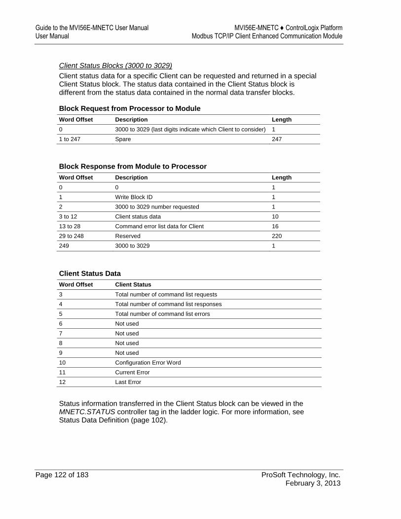
Guide to the MVI56E-MNETC User Manual MVI56E-MNETC ♦ ControlLogix Platform User Manual Modbus TCP/IP Client Enhanced Communication Module
Page 122 of 183 ProSoft Technology, Inc. February 3, 2013
Client Status Blocks (3000 to 3029)
Client status data for a specific Client can be requested and returned in a special Client Status block. The status data contained in the Client Status block is different from the status data contained in the normal data transfer blocks.
Block Request from Processor to Module
Word Offset Description Length
0 3000 to 3029 (last digits indicate which Client to consider) 1
1 to 247 Spare 247
Block Response from Module to Processor
Word Offset Description Length
0 0 1
1 Write Block ID 1
2 3000 to 3029 number requested 1
3 to 12 Client status data 10
13 to 28 Command error list data for Client 16
29 to 248 Reserved 220
249 3000 to 3029 1
Client Status Data
Word Offset Client Status
3 Total number of command list requests
4 Total number of command list responses
5 Total number of command list errors
6 Not used
7 Not used
8 Not used
9 Not used
10 Configuration Error Word
11 Current Error
12 Last Error
Status information transferred in the Client Status block can be viewed in the MNETC.STATUS controller tag in the ladder logic. For more information, see Status Data Definition (page 102).
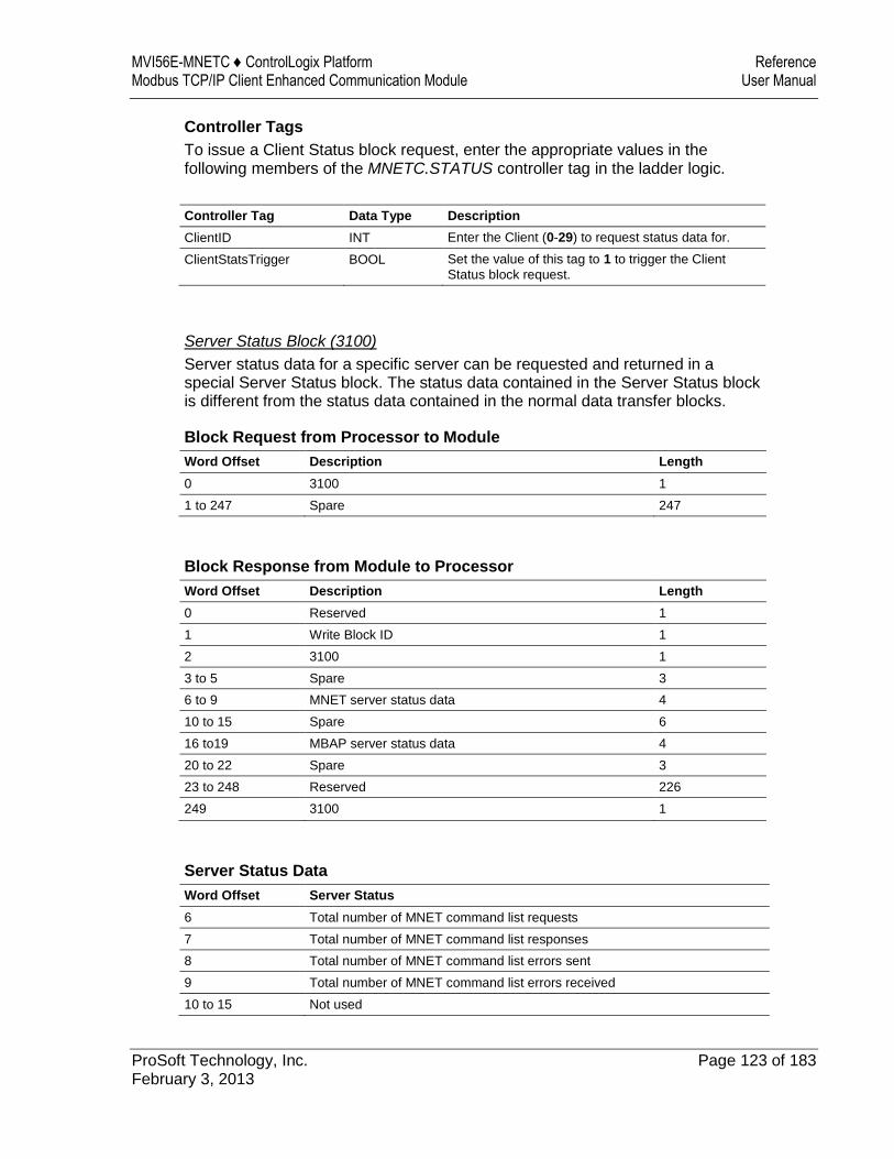
MVI56E-MNETC ♦ ControlLogix Platform Reference Modbus TCP/IP Client Enhanced Communication Module User Manual
ProSoft Technology, Inc. Page 123 of 183 February 3, 2013
Controller Tags
To issue a Client Status block request, enter the appropriate values in the following members of the MNETC.STATUS controller tag in the ladder logic.
Controller Tag Data Type Description
ClientID INT Enter the Client (0-29) to request status data for.
ClientStatsTrigger BOOL Set the value of this tag to 1 to trigger the Client
Status block request.
Server Status Block (3100)
Server status data for a specific server can be requested and returned in a special Server Status block. The status data contained in the Server Status block is different from the status data contained in the normal data transfer blocks.
Block Request from Processor to Module
Word Offset Description Length
0 3100 1
1 to 247 Spare 247
Block Response from Module to Processor
Word Offset Description Length
0 Reserved 1
1 Write Block ID 1
2 3100 1
3 to 5 Spare 3
6 to 9 MNET server status data 4
10 to 15 Spare 6
16 to19 MBAP server status data 4
20 to 22 Spare 3
23 to 248 Reserved 226
249 3100 1
Server Status Data
Word Offset Server Status
6 Total number of MNET command list requests
7 Total number of MNET command list responses
8 Total number of MNET command list errors sent
9 Total number of MNET command list errors received
10 to 15 Not used
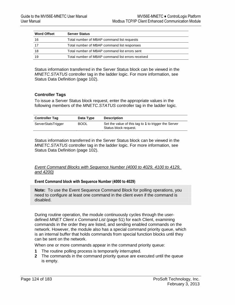
Guide to the MVI56E-MNETC User Manual MVI56E-MNETC ♦ ControlLogix Platform User Manual Modbus TCP/IP Client Enhanced Communication Module
Page 124 of 183 ProSoft Technology, Inc. February 3, 2013
Word Offset Server Status
16 Total number of MBAP command list requests
17 Total number of MBAP command list responses
18 Total number of MBAP command list errors sent
19 Total number of MBAP command list errors received
Status information transferred in the Server Status block can be viewed in the MNETC.STATUS controller tag in the ladder logic. For more information, see Status Data Definition (page 102).
Controller Tags
To issue a Server Status block request, enter the appropriate values in the following members of the MNETC.STATUS controller tag in the ladder logic.
Controller Tag Data Type Description
ServerStatsTrigger BOOL Set the value of this tag to 1 to trigger the Server
Status block request.
Status information transferred in the Server Status block can be viewed in the MNETC.STATUS controller tag in the ladder logic. For more information, see Status Data Definition (page 102).
Event Command Blocks with Sequence Number (4000 to 4029, 4100 to 4129, and 4200)
Event Command block with Sequence Number (4000 to 4029)
Note: To use the Event Sequence Command Block for polling operations, you need to configure at least one command in the client even if the command is disabled.
During routine operation, the module continuously cycles through the user-defined MNET Client x Command List (page 51) for each Client, examining commands in the order they are listed, and sending enabled commands on the network. However, the module also has a special command priority queue, which is an internal buffer that holds commands from special function blocks until they can be sent on the network.
When one or more commands appear in the command priority queue:
1 The routine polling process is temporarily interrupted. 2 The commands in the command priority queue are executed until the queue
is empty.
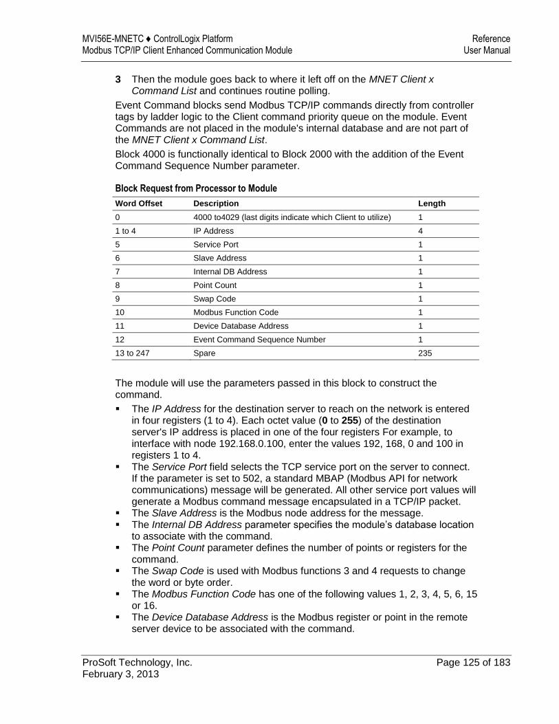
MVI56E-MNETC ♦ ControlLogix Platform Reference Modbus TCP/IP Client Enhanced Communication Module User Manual
ProSoft Technology, Inc. Page 125 of 183 February 3, 2013
3 Then the module goes back to where it left off on the MNET Client x Command List and continues routine polling.
Event Command blocks send Modbus TCP/IP commands directly from controller tags by ladder logic to the Client command priority queue on the module. Event Commands are not placed in the module's internal database and are not part of the MNET Client x Command List.
Block 4000 is functionally identical to Block 2000 with the addition of the Event Command Sequence Number parameter.
Block Request from Processor to Module
Word Offset Description Length
0 4000 to4029 (last digits indicate which Client to utilize) 1
1 to 4 IP Address 4
5 Service Port 1
6 Slave Address 1
7 Internal DB Address 1
8 Point Count 1
9 Swap Code 1
10 Modbus Function Code 1
11 Device Database Address 1
12 Event Command Sequence Number 1
13 to 247 Spare 235
The module will use the parameters passed in this block to construct the command.
The IP Address for the destination server to reach on the network is entered in four registers (1 to 4). Each octet value (0 to 255) of the destination server's IP address is placed in one of the four registers For example, to interface with node 192.168.0.100, enter the values 192, 168, 0 and 100 in registers 1 to 4.
The Service Port field selects the TCP service port on the server to connect. If the parameter is set to 502, a standard MBAP (Modbus API for network communications) message will be generated. All other service port values will generate a Modbus command message encapsulated in a TCP/IP packet.
The Slave Address is the Modbus node address for the message. The Internal DB Address parameter specifies the module’s database location
to associate with the command. The Point Count parameter defines the number of points or registers for the
command. The Swap Code is used with Modbus functions 3 and 4 requests to change
the word or byte order. The Modbus Function Code has one of the following values 1, 2, 3, 4, 5, 6, 15
or 16. The Device Database Address is the Modbus register or point in the remote
server device to be associated with the command.
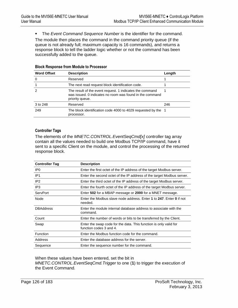
Guide to the MVI56E-MNETC User Manual MVI56E-MNETC ♦ ControlLogix Platform User Manual Modbus TCP/IP Client Enhanced Communication Module
Page 126 of 183 ProSoft Technology, Inc. February 3, 2013
The Event Command Sequence Number is the identifier for the command.
The module then places the command in the command priority queue (if the queue is not already full; maximum capacity is 16 commands), and returns a response block to tell the ladder logic whether or not the command has been successfully added to the queue.
Block Response from Module to Processor
Word Offset Description Length
0 Reserved 1
1 The next read request block identification code. 1
2 The result of the event request. 1 indicates the command was issued. 0 indicates no room was found in the command priority queue.
1
3 to 248 Reserved 246
249 The block identification code 4000 to 4029 requested by the processor.
1
Controller Tags
The elements of the MNETC.CONTROL.EventSeqCmd[x] controller tag array contain all the values needed to build one Modbus TCP/IP command, have it sent to a specific Client on the module, and control the processing of the returned response block.
Controller Tag Description
IP0 Enter the first octet of the IP address of the target Modbus server.
IP1 Enter the second octet of the IP address of the target Modbus server.
IP2 Enter the third octet of the IP address of the target Modbus server.
IP3 Enter the fourth octet of the IP address of the target Modbus server.
ServPort Enter 502 for a MBAP message or 2000 for a MNET message.
Node Enter the Modbus slave node address. Enter 1 to 247. Enter 0 if not
needed.
DBAddress Enter the module internal database address to associate with the command.
Count Enter the number of words or bits to be transferred by the Client.
Swap Enter the swap code for the data. This function is only valid for function codes 3 and 4.
Function Enter the Modbus function code for the command.
Address Enter the database address for the server.
Sequence Enter the sequence number for the command.
When these values have been entered, set the bit in MNETC.CONTROL.EventSeqCmd.Trigger to one (1) to trigger the execution of the Event Command.
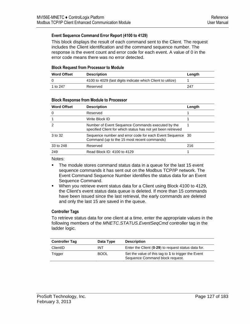
MVI56E-MNETC ♦ ControlLogix Platform Reference Modbus TCP/IP Client Enhanced Communication Module User Manual
ProSoft Technology, Inc. Page 127 of 183 February 3, 2013
Event Sequence Command Error Report (4100 to 4129)
This block displays the result of each command sent to the Client. The request includes the Client identification and the command sequence number. The response is the event count and error code for each event. A value of 0 in the error code means there was no error detected.
Block Request from Processor to Module
Word Offset Description Length
0 4100 to 4029 (last digits indicate which Client to utilize) 1
1 to 247 Reserved 247
Block Response from Module to Processor
Word Offset Description Length
0 Reserved 1
1 Write Block ID 1
2 Number of Event Sequence Commands executed by the specified Client for which status has not yet been retrieved
1
3 to 32 Sequence number and error code for each Event Sequence Command (up to the 15 most recent commands)
30
33 to 248 Reserved 216
249 Read Block ID: 4100 to 4129 1
Notes:
The module stores command status data in a queue for the last 15 event sequence commands it has sent out on the Modbus TCP/IP network. The Event Command Sequence Number identifies the status data for an Event Sequence Command.
When you retrieve event status data for a Client using Block 4100 to 4129, the Client's event status data queue is deleted. If more than 15 commands have been issued since the last retrieval, the early commands are deleted and only the last 15 are saved in the queue.
Controller Tags
To retrieve status data for one client at a time, enter the appropriate values in the following members of the MNETC.STATUS.EventSeqCmd controller tag in the ladder logic.
Controller Tag Data Type Description
ClientID INT Enter the Client (0-29) to request status data for.
Trigger BOOL Set the value of this tag to 1 to trigger the Event
Sequence Command block request.

Guide to the MVI56E-MNETC User Manual MVI56E-MNETC ♦ ControlLogix Platform User Manual Modbus TCP/IP Client Enhanced Communication Module
Page 128 of 183 ProSoft Technology, Inc. February 3, 2013
Event Sequence Command Count Status (4200)
This block displays the command queue status data for all clients. The response is the priority command queue count and the Event Sequence Command status queue count.
Block Request from Processor to Module
Word Offset Description Length
0 4200 1
1 to 247 Reserved 247
Block Response from Module to Processor
Word Offset Description Length
0 Reserved 1
1 Write Block ID 1
2 to 31 Command queue status data for each Client 30
32 to 248 Reserved 216
249 Read Block ID: 4100 to 4129 1
In words 2 to 31 of this block, each word has two bytes:
Byte 1: Number of Event sequence commands for which status has not yet been retrieved (up to 15). This corresponds to the MNETC.STATUS.EventSeqCmdPending.Client[x]_QueueCount controller tag.
Byte 2: Total number of commands waiting in the command queue. This includes Event Commands, Event Commands with Sequence Numbers, and Command Control messages. This corresponds to the MNETC.STATUS.EventSeqCmdPending.Client[x]_WaitingMsgs controller tag.
Controller Tags
To retrieve status data for all 30 clients at a time, enter the appropriate values in the following members of the MNETC.STATUS.EventSeqCmd controller tag in the ladder logic.
Controller Tag Data Type Description
Trigger BOOL Set the value of this tag to 1 to trigger the command
queue status data request.
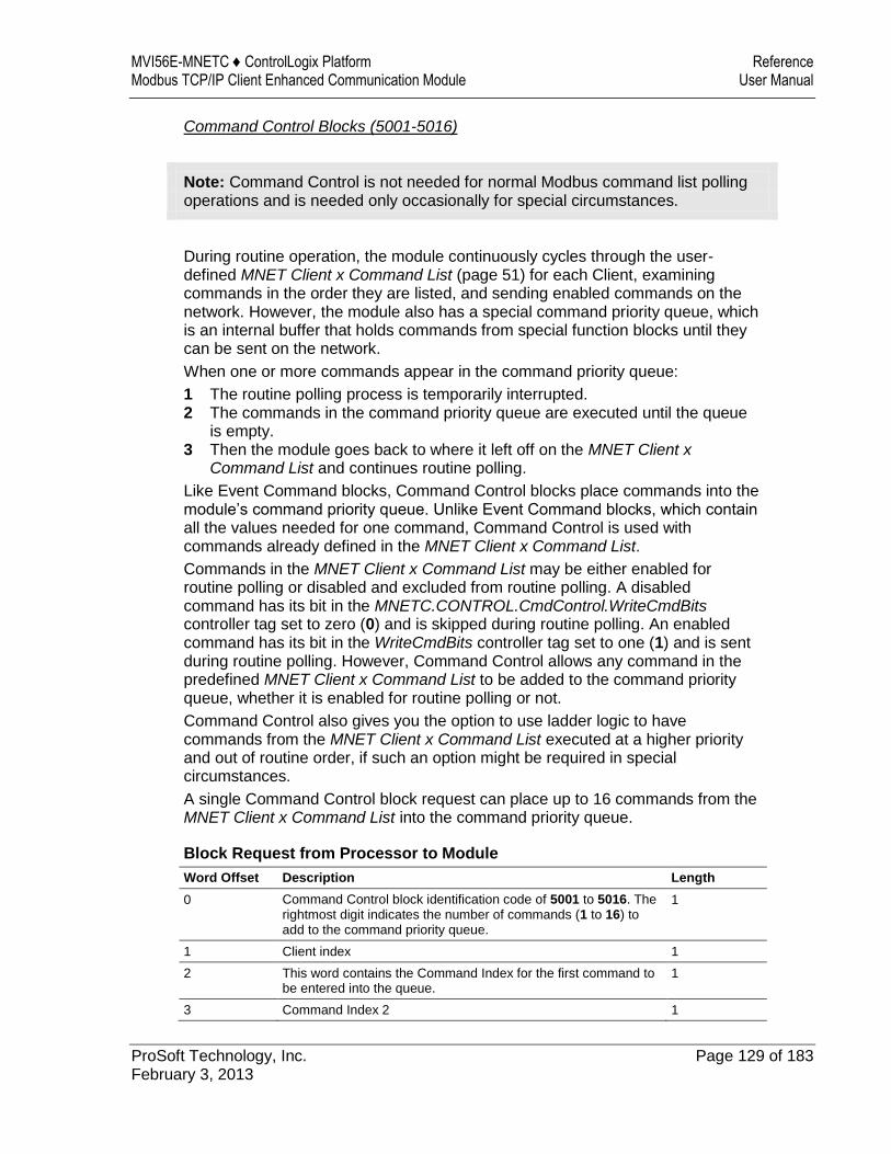
MVI56E-MNETC ♦ ControlLogix Platform Reference Modbus TCP/IP Client Enhanced Communication Module User Manual
ProSoft Technology, Inc. Page 129 of 183 February 3, 2013
Command Control Blocks (5001-5016)
Note: Command Control is not needed for normal Modbus command list polling operations and is needed only occasionally for special circumstances.
During routine operation, the module continuously cycles through the user-defined MNET Client x Command List (page 51) for each Client, examining commands in the order they are listed, and sending enabled commands on the network. However, the module also has a special command priority queue, which is an internal buffer that holds commands from special function blocks until they can be sent on the network.
When one or more commands appear in the command priority queue:
1 The routine polling process is temporarily interrupted. 2 The commands in the command priority queue are executed until the queue
is empty. 3 Then the module goes back to where it left off on the MNET Client x
Command List and continues routine polling.
Like Event Command blocks, Command Control blocks place commands into the module’s command priority queue. Unlike Event Command blocks, which contain all the values needed for one command, Command Control is used with commands already defined in the MNET Client x Command List.
Commands in the MNET Client x Command List may be either enabled for routine polling or disabled and excluded from routine polling. A disabled command has its bit in the MNETC.CONTROL.CmdControl.WriteCmdBits controller tag set to zero (0) and is skipped during routine polling. An enabled command has its bit in the WriteCmdBits controller tag set to one (1) and is sent during routine polling. However, Command Control allows any command in the predefined MNET Client x Command List to be added to the command priority queue, whether it is enabled for routine polling or not.
Command Control also gives you the option to use ladder logic to have commands from the MNET Client x Command List executed at a higher priority and out of routine order, if such an option might be required in special circumstances.
A single Command Control block request can place up to 16 commands from the MNET Client x Command List into the command priority queue.
Block Request from Processor to Module
Word Offset Description Length
0 Command Control block identification code of 5001 to 5016. The rightmost digit indicates the number of commands (1 to 16) to add to the command priority queue.
1
1 Client index 1
2 This word contains the Command Index for the first command to be entered into the queue.
1
3 Command Index 2 1
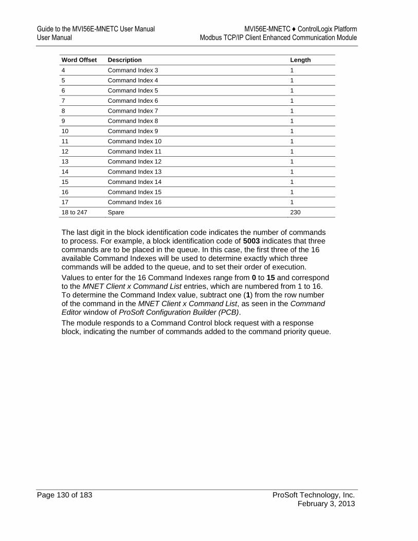
Guide to the MVI56E-MNETC User Manual MVI56E-MNETC ♦ ControlLogix Platform User Manual Modbus TCP/IP Client Enhanced Communication Module
Page 130 of 183 ProSoft Technology, Inc. February 3, 2013
Word Offset Description Length
4 Command Index 3 1
5 Command Index 4 1
6 Command Index 5 1
7 Command Index 6 1
8 Command Index 7 1
9 Command Index 8 1
10 Command Index 9 1
11 Command Index 10 1
12 Command Index 11 1
13 Command Index 12 1
14 Command Index 13 1
15 Command Index 14 1
16 Command Index 15 1
17 Command Index 16 1
18 to 247 Spare 230
The last digit in the block identification code indicates the number of commands to process. For example, a block identification code of 5003 indicates that three commands are to be placed in the queue. In this case, the first three of the 16 available Command Indexes will be used to determine exactly which three commands will be added to the queue, and to set their order of execution.
Values to enter for the 16 Command Indexes range from 0 to 15 and correspond to the MNET Client x Command List entries, which are numbered from 1 to 16. To determine the Command Index value, subtract one (1) from the row number of the command in the MNET Client x Command List, as seen in the Command Editor window of ProSoft Configuration Builder (PCB).
The module responds to a Command Control block request with a response block, indicating the number of commands added to the command priority queue.
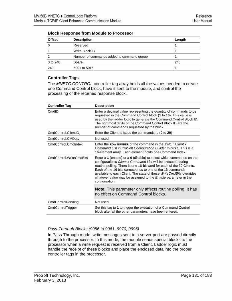
MVI56E-MNETC ♦ ControlLogix Platform Reference Modbus TCP/IP Client Enhanced Communication Module User Manual
ProSoft Technology, Inc. Page 131 of 183 February 3, 2013
Block Response from Module to Processor
Offset Description Length
0 Reserved 1
1 Write Block ID 1
2 Number of commands added to command queue 1
3 to 248 Spare 246
249 5001 to 5016 1
Controller Tags
The MNETC.CONTROL controller tag array holds all the values needed to create one Command Control block, have it sent to the module, and control the processing of the returned response block.
Controller Tag Description
CmdID Enter a decimal value representing the quantity of commands to be requested in the Command Control block (1 to 16). This value is
used by the ladder logic to generate the Command Control Block ID. The rightmost digits of the Command Control Block ID are the number of commands requested by the block.
CmdControl.ClientID Enter the Client to issue the commands to (0 to 29)
CmdControl.CMDqty Not used
CmdControl.CmdIndex Enter the ROW NUMBER of the command in the MNET Client x Command List in ProSoft Configuration Builder minus 1. This is a 16-element array. Each element holds one Command Index.
CmdControl.WriteCmdBits Enter a 1 (enable) or a 0 (disable) to select which commands on the
configuration's Client x Command List will be executed during routine polling. There is one 16-bit word for each of the 30 Clients. Each of the 16 bits corresponds to one of the 16 commands available to each Client. The state of these WriteCmdBits overrides whatever value may be assigned to the Enable parameter in the configuration.
Note: This parameter only affects routine polling. It has no effect on Command Control blocks.
CmdControlPending Not used
CmdControlTrigger Set this tag to 1 to trigger the execution of a Command Control block after all the other parameters have been entered.
Pass-Through Blocks (9956 to 9961, 9970, 9996)
In Pass-Through mode, write messages sent to a server port are passed directly through to the processor. In this mode, the module sends special blocks to the processor when a write request is received from a Client. Ladder logic must handle the receipt of these blocks and place the enclosed data into the proper controller tags in the processor.
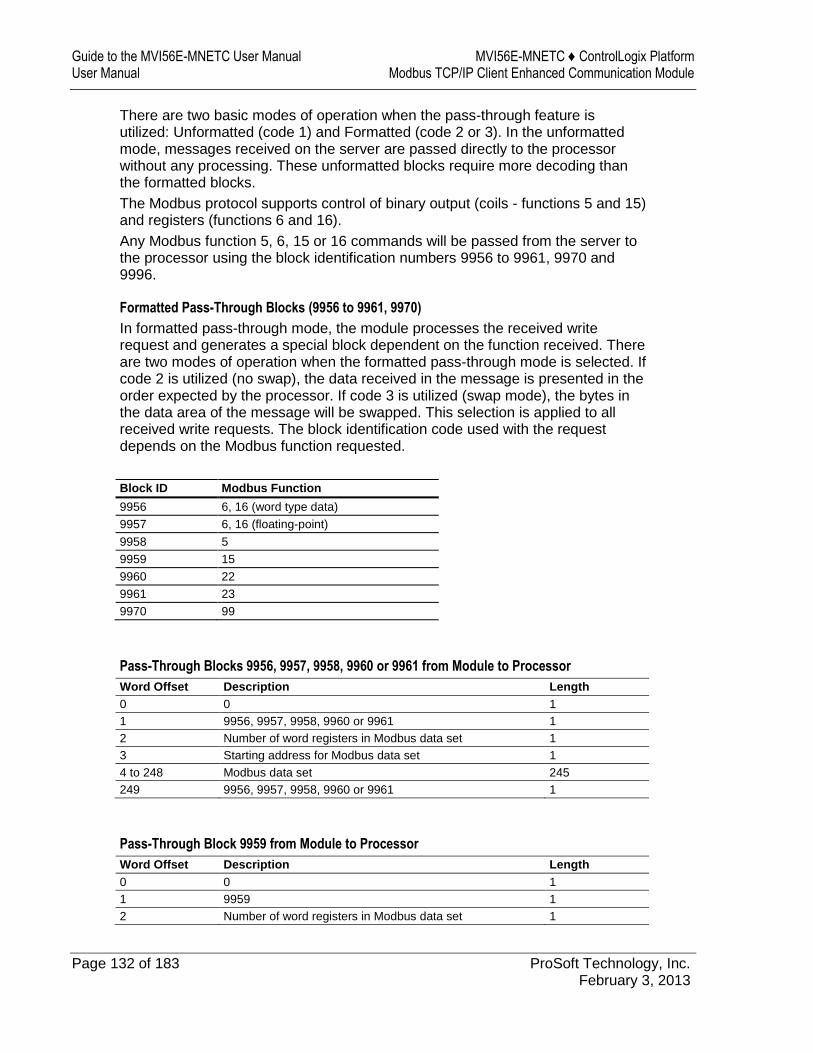
Guide to the MVI56E-MNETC User Manual MVI56E-MNETC ♦ ControlLogix Platform User Manual Modbus TCP/IP Client Enhanced Communication Module
Page 132 of 183 ProSoft Technology, Inc. February 3, 2013
There are two basic modes of operation when the pass-through feature is utilized: Unformatted (code 1) and Formatted (code 2 or 3). In the unformatted mode, messages received on the server are passed directly to the processor without any processing. These unformatted blocks require more decoding than the formatted blocks.
The Modbus protocol supports control of binary output (coils - functions 5 and 15) and registers (functions 6 and 16).
Any Modbus function 5, 6, 15 or 16 commands will be passed from the server to the processor using the block identification numbers 9956 to 9961, 9970 and 9996.
Formatted Pass-Through Blocks (9956 to 9961, 9970)
In formatted pass-through mode, the module processes the received write request and generates a special block dependent on the function received. There are two modes of operation when the formatted pass-through mode is selected. If code 2 is utilized (no swap), the data received in the message is presented in the order expected by the processor. If code 3 is utilized (swap mode), the bytes in the data area of the message will be swapped. This selection is applied to all received write requests. The block identification code used with the request depends on the Modbus function requested.
Block ID Modbus Function
9956 6, 16 (word type data)
9957 6, 16 (floating-point)
9958 5
9959 15
9960 22
9961 23
9970 99
Pass-Through Blocks 9956, 9957, 9958, 9960 or 9961 from Module to Processor
Word Offset Description Length
0 0 1
1 9956, 9957, 9958, 9960 or 9961 1
2 Number of word registers in Modbus data set 1
3 Starting address for Modbus data set 1
4 to 248 Modbus data set 245
249 9956, 9957, 9958, 9960 or 9961 1
Pass-Through Block 9959 from Module to Processor
Word Offset Description Length
0 0 1
1 9959 1
2 Number of word registers in Modbus data set 1
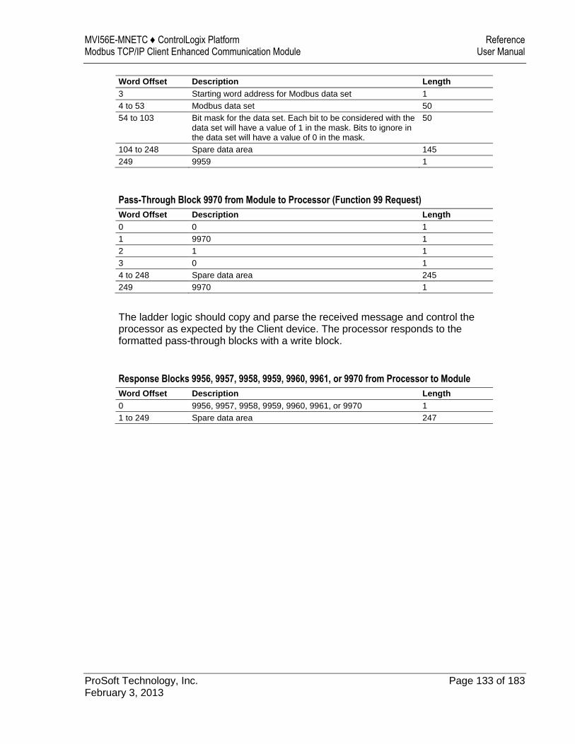
MVI56E-MNETC ♦ ControlLogix Platform Reference Modbus TCP/IP Client Enhanced Communication Module User Manual
ProSoft Technology, Inc. Page 133 of 183 February 3, 2013
Word Offset Description Length
3 Starting word address for Modbus data set 1
4 to 53 Modbus data set 50
54 to 103 Bit mask for the data set. Each bit to be considered with the data set will have a value of 1 in the mask. Bits to ignore in the data set will have a value of 0 in the mask.
50
104 to 248 Spare data area 145
249 9959 1
Pass-Through Block 9970 from Module to Processor (Function 99 Request)
Word Offset Description Length
0 0 1
1 9970 1
2 1 1
3 0 1
4 to 248 Spare data area 245
249 9970 1
The ladder logic should copy and parse the received message and control the processor as expected by the Client device. The processor responds to the formatted pass-through blocks with a write block.
Response Blocks 9956, 9957, 9958, 9959, 9960, 9961, or 9970 from Processor to Module
Word Offset Description Length
0 9956, 9957, 9958, 9959, 9960, 9961, or 9970 1
1 to 249 Spare data area 247
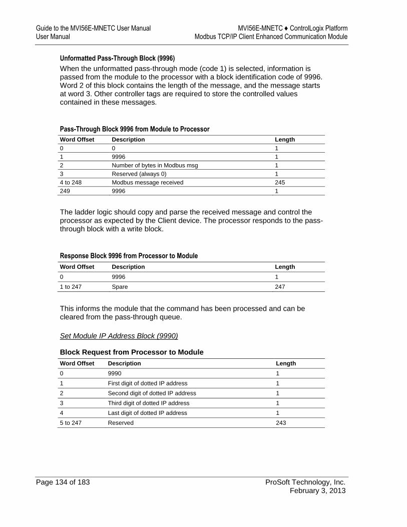
Guide to the MVI56E-MNETC User Manual MVI56E-MNETC ♦ ControlLogix Platform User Manual Modbus TCP/IP Client Enhanced Communication Module
Page 134 of 183 ProSoft Technology, Inc. February 3, 2013
Unformatted Pass-Through Block (9996)
When the unformatted pass-through mode (code 1) is selected, information is passed from the module to the processor with a block identification code of 9996. Word 2 of this block contains the length of the message, and the message starts at word 3. Other controller tags are required to store the controlled values contained in these messages.
Pass-Through Block 9996 from Module to Processor
Word Offset Description Length
0 0 1
1 9996 1
2 Number of bytes in Modbus msg 1
3 Reserved (always 0) 1
4 to 248 Modbus message received 245
249 9996 1
The ladder logic should copy and parse the received message and control the processor as expected by the Client device. The processor responds to the pass-through block with a write block.
Response Block 9996 from Processor to Module
Word Offset Description Length
0 9996 1
1 to 247 Spare 247
This informs the module that the command has been processed and can be cleared from the pass-through queue.
Set Module IP Address Block (9990)
Block Request from Processor to Module
Word Offset Description Length
0 9990 1
1 First digit of dotted IP address 1
2 Second digit of dotted IP address 1
3 Third digit of dotted IP address 1
4 Last digit of dotted IP address 1
5 to 247 Reserved 243
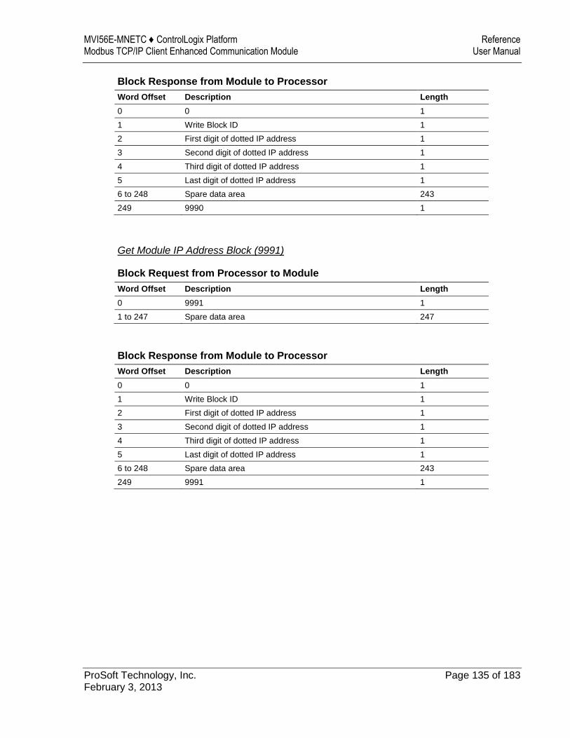
MVI56E-MNETC ♦ ControlLogix Platform Reference Modbus TCP/IP Client Enhanced Communication Module User Manual
ProSoft Technology, Inc. Page 135 of 183 February 3, 2013
Block Response from Module to Processor
Word Offset Description Length
0 0 1
1 Write Block ID 1
2 First digit of dotted IP address 1
3 Second digit of dotted IP address 1
4 Third digit of dotted IP address 1
5 Last digit of dotted IP address 1
6 to 248 Spare data area 243
249 9990 1
Get Module IP Address Block (9991)
Block Request from Processor to Module
Word Offset Description Length
0 9991 1
1 to 247 Spare data area 247
Block Response from Module to Processor
Word Offset Description Length
0 0 1
1 Write Block ID 1
2 First digit of dotted IP address 1
3 Second digit of dotted IP address 1
4 Third digit of dotted IP address 1
5 Last digit of dotted IP address 1
6 to 248 Spare data area 243
249 9991 1
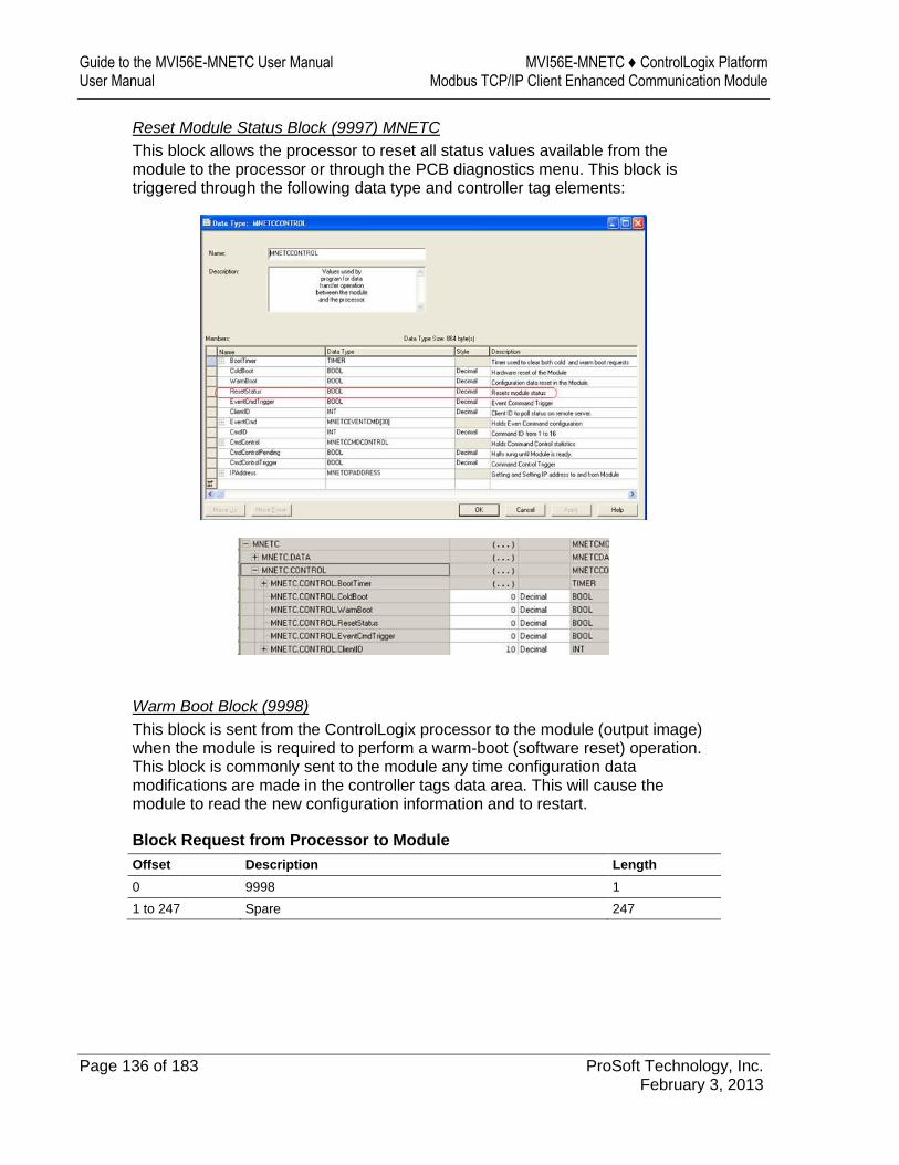
Guide to the MVI56E-MNETC User Manual MVI56E-MNETC ♦ ControlLogix Platform User Manual Modbus TCP/IP Client Enhanced Communication Module
Page 136 of 183 ProSoft Technology, Inc. February 3, 2013
Reset Module Status Block (9997) MNETC
This block allows the processor to reset all status values available from the module to the processor or through the PCB diagnostics menu. This block is triggered through the following data type and controller tag elements:
Warm Boot Block (9998)
This block is sent from the ControlLogix processor to the module (output image) when the module is required to perform a warm-boot (software reset) operation. This block is commonly sent to the module any time configuration data modifications are made in the controller tags data area. This will cause the module to read the new configuration information and to restart.
Block Request from Processor to Module
Offset Description Length
0 9998 1
1 to 247 Spare 247

MVI56E-MNETC ♦ ControlLogix Platform Reference Modbus TCP/IP Client Enhanced Communication Module User Manual
ProSoft Technology, Inc. Page 137 of 183 February 3, 2013
Cold Boot Block (9999)
This block is sent from the ControlLogix processor to the module (output image) when the module is required to perform the cold boot (hardware reset) operation. This block is sent to the module when a hardware problem is detected by the ladder logic that requires a hardware reset.
Block Request from Processor to Module
Word Offset Description Length
0 9999 1
1 to 247 Spare 247
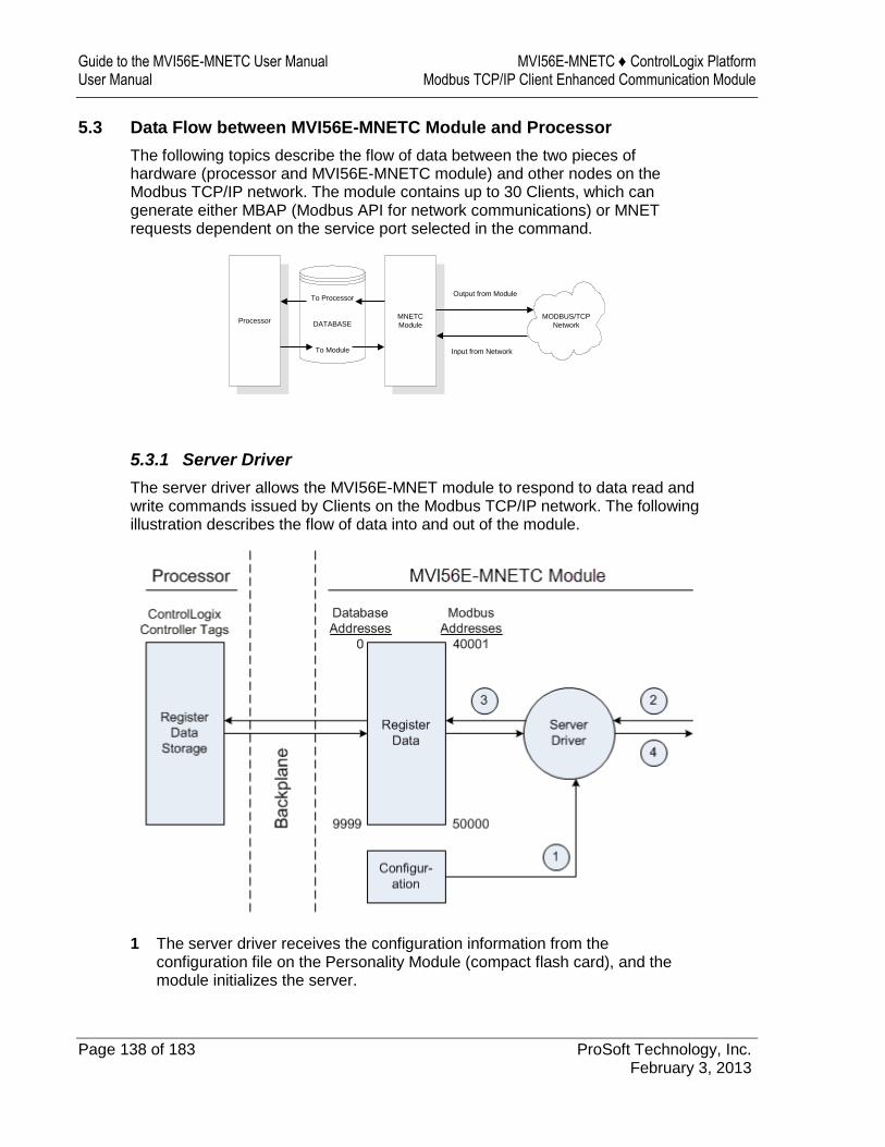
Guide to the MVI56E-MNETC User Manual MVI56E-MNETC ♦ ControlLogix Platform User Manual Modbus TCP/IP Client Enhanced Communication Module
Page 138 of 183 ProSoft Technology, Inc. February 3, 2013
5.3 Data Flow between MVI56E-MNETC Module and Processor
The following topics describe the flow of data between the two pieces of hardware (processor and MVI56E-MNETC module) and other nodes on the Modbus TCP/IP network. The module contains up to 30 Clients, which can generate either MBAP (Modbus API for network communications) or MNET requests dependent on the service port selected in the command.
To Processor
DATABASE
To Module
ProcessorMNETC
Module
MODBUS/TCP
Network
Output from Module
Input from Network
5.3.1 Server Driver
The server driver allows the MVI56E-MNET module to respond to data read and write commands issued by Clients on the Modbus TCP/IP network. The following illustration describes the flow of data into and out of the module.
1 The server driver receives the configuration information from the configuration file on the Personality Module (compact flash card), and the module initializes the server.

MVI56E-MNETC ♦ ControlLogix Platform Reference Modbus TCP/IP Client Enhanced Communication Module User Manual
ProSoft Technology, Inc. Page 139 of 183 February 3, 2013
2 A host device, such as a Modicon PLC or an HMI application, issues a read or write command to the module’s node address. The server driver validates the message before accepting it into the module. If the message is considered invalid, an error response is returned to the originating Client node.
3 After the module accepts the command, the module processes the data contained in the command.
If the command is a read command, the data is read out of the database and a response message is built. If the command is a write command, the data is written directly into the database and a response message is built. If the command is a write command and the pass-through feature is utilized, the write message is transferred to the processor ladder logic and is not written directly into the module’s database, unless it is returned as a change in the output image that overwrites data in the WriteData area as a result of such ladder logic processing.
4 After the data processing has been completed in Step 3, a response is issued to the originating Client node.
Counters are available in the Status Block that permit the ladder logic program to determine the level of activity of the server driver.
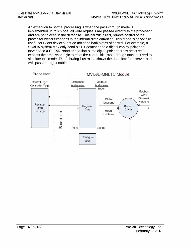
Guide to the MVI56E-MNETC User Manual MVI56E-MNETC ♦ ControlLogix Platform User Manual Modbus TCP/IP Client Enhanced Communication Module
Page 140 of 183 ProSoft Technology, Inc. February 3, 2013
An exception to normal processing is when the pass-through mode is implemented. In this mode, all write requests are passed directly to the processor and are not placed in the database. This permits direct, remote control of the processor without changes in the intermediate database. This mode is especially useful for Client devices that do not send both states of control. For example, a SCADA system may only send a SET command to a digital control point and never send a CLEAR command to that same digital point address because it expects the processor logic to reset the control bit. Pass-through must be used to simulate this mode. The following illustration shows the data flow for a server port with pass-through enabled.

MVI56E-MNETC ♦ ControlLogix Platform Reference Modbus TCP/IP Client Enhanced Communication Module User Manual
ProSoft Technology, Inc. Page 141 of 183 February 3, 2013
5.3.2 Client Driver
In the Client driver, the MVI56E-MNETC module issues read or write commands to servers on the Modbus TCP/IP network using up to 30 simulated Clients. The commands originate either from the module's user-configured Client x Command List for each Client, or directly from the processor as Event Commands. The commands from the Client x Command List are executed either via routine polling or as a result of special Command Control block requests from the processor. Client status data is returned to the processor in special Client Status blocks. The following flowchart describes the flow of data into and out of the module.
1 The Client driver obtains configuration data when the module restarts. This includes the timeout parameters and the Command List. These values are used by the driver to determine the types of commands to be issued to servers on the Modbus TCP/IP network.
2 When configured, the Client driver begins transmitting read and/or write commands to servers on the network. The data for write commands is obtained from the module's internal database.
3 Assuming successful processing by the server specified in the command, a response message is received into the Client driver for processing.
4 Data received from the server is passed into the module's internal database, if the command was a read command. General module status information is routinely returned to the processor in the input images.
5 Status data for a specific Client can be requested by the processor and returned in a special Client Status block.
6 Special functions, such as Event Commands and Command Control options, can be generated by the processor and sent to the Client driver for action.

Guide to the MVI56E-MNETC User Manual MVI56E-MNETC ♦ ControlLogix Platform User Manual Modbus TCP/IP Client Enhanced Communication Module
Page 142 of 183 ProSoft Technology, Inc. February 3, 2013
5.3.3 Client Command List
In order for the Client to function, the module's Client Command List must be defined in the MNET Client x Commands section of the configuration. This list contains up to 16 individual entries, with each entry containing the information required to construct a valid command. This includes the following:
Command enable mode: (0) disabled, (1) continuous or (2) conditional. Conditional enabling applies only to write commands.
IP address and service port to connect to on the remote server Slave Node Address Command Type - Read or Write up to 100 words per command Database Source and Destination Register Address - Determines where data
will be placed and/or obtained Count - Select the number of words to be transferred - 1 to 100 Poll Delay - 1/10th seconds
For information on troubleshooting commands, see Client Command Errors (page 106).
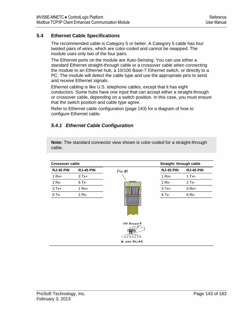
MVI56E-MNETC ♦ ControlLogix Platform Reference Modbus TCP/IP Client Enhanced Communication Module User Manual
ProSoft Technology, Inc. Page 143 of 183 February 3, 2013
5.4 Ethernet Cable Specifications
The recommended cable is Category 5 or better. A Category 5 cable has four twisted pairs of wires, which are color-coded and cannot be swapped. The module uses only two of the four pairs.
The Ethernet ports on the module are Auto-Sensing. You can use either a standard Ethernet straight-through cable or a crossover cable when connecting the module to an Ethernet hub, a 10/100 Base-T Ethernet switch, or directly to a PC. The module will detect the cable type and use the appropriate pins to send and receive Ethernet signals.
Ethernet cabling is like U.S. telephone cables, except that it has eight conductors. Some hubs have one input that can accept either a straight-through or crossover cable, depending on a switch position. In this case, you must ensure that the switch position and cable type agree.
Refer to Ethernet cable configuration (page 143) for a diagram of how to configure Ethernet cable.
5.4.1 Ethernet Cable Configuration
Note: The standard connector view shown is color-coded for a straight-through cable.
Crossover cable Straight- through cable
RJ-45 PIN RJ-45 PIN
1 Rx+ 3 Tx+
2 Rx- 6 Tx-
3 Tx+ 1 Rx+
6 Tx- 2 Rx-
RJ-45 PIN RJ-45 PIN
1 Rx+ 1 Tx+
2 Rx- 2 Tx-
3 Tx+ 3 Rx+
6 Tx- 6 Rx-

Guide to the MVI56E-MNETC User Manual MVI56E-MNETC ♦ ControlLogix Platform User Manual Modbus TCP/IP Client Enhanced Communication Module
Page 144 of 183 ProSoft Technology, Inc. February 3, 2013
5.4.2 Ethernet Performance
Ethernet performance on the MVI56E-MNETC module can affect the operation of the MNETC application ports in the following ways.
Accessing the web interface (refreshing the page, downloading files, and so on) may affect MNETC performance
High Ethernet traffic may impact MNETC performance (consider CIPconnect (page 66) for these applications and disconnect the module Ethernet port from the network).

MVI56E-MNETC ♦ ControlLogix Platform Reference Modbus TCP/IP Client Enhanced Communication Module User Manual
ProSoft Technology, Inc. Page 145 of 183 February 3, 2013
5.5 Modbus Protocol Specification
The following pages give additional reference information regarding the Modbus protocol commands supported by the MVI56E-MNETC.
5.5.1 About the Modbus TCP/IP Protocol
MODBUS is a widely-used protocol originally developed by Modicon in 1978. Since that time, the protocol has been adopted as a standard throughout the automation industry.
The original MODBUS specification uses a serial connection to communicate commands and data between Client and server devices on a network. Later enhancements to the protocol allow communication over Ethernet networks using TCP/IP as a "wrapper" for the MODBUS protocol. This protocol is known as MODBUS TCP/IP.
MODBUS TCP/IP is a Client/server protocol. The Client establishes a connection to the remote server. When the connection is established, the Client sends the MODBUS TCP/IP commands to the server. The MVI56E-MNETC module simulates up to 30 Clients, and works both as a Client and a server.
Aside from the benefits of Ethernet versus serial communications (including performance, distance, and flexibility) for industrial networks, the MODBUS TCP/IP protocol allows for remote administration and control of devices over an Internet connection. It is important to note that not all Internet protocols are implemented in the module; for example, HTTP and SMTP protocols are not available. Nevertheless, the efficiency, scalability, and low cost of a MODBUS TCP/IP network make this an ideal solution for industrial applications.
The MVI56E-MNETC module acts as an input/output module between devices on a MODBUS TCP/IP network and the Rockwell Automation backplane. The module uses an internal database to pass data and commands between the processor and the Client and server devices on the MODBUS TCP/IP network.

Guide to the MVI56E-MNETC User Manual MVI56E-MNETC ♦ ControlLogix Platform User Manual Modbus TCP/IP Client Enhanced Communication Module
Page 146 of 183 ProSoft Technology, Inc. February 3, 2013
5.5.2 Read Coil Status (Function Code 01)
Query
This function allows the user to obtain the ON/OFF status of logic coils used to control discrete outputs from the addressed server only. Broadcast mode is not supported with this function code. In addition to the server address and function fields, the message requires that the information field contain the initial coil address to be read (Starting Address) and the number of locations that will be interrogated to obtain status data.
The addressing allows up to 2000 coils to be obtained at each request; however, the specific server device may have restrictions that lower the maximum quantity. The coils are numbered from zero; (coil number 1 = zero, coil number 2 = one, coil number 3 = two, and so on).
The following table is a sample read output status request to read coils 0020 to 0056 from server device number 11.
Adr Func Data Start Pt Hi
Data Start Pt Lo
Data # Of Pts Ho
Data # Of Pts Lo
Error Check Field
11 01 00 13 00 25 CRC
Response
An example response to Read Coil Status is as shown in Figure C2. The data is packed one bit for each coil. The response includes the server address, function code, quantity of data characters, the data characters, and error checking. Data will be packed with one bit for each coil (1 = ON, 0 = OFF). The low order bit of the first character contains the addressed coil, and the remainder follow. For coil quantities that are not even multiples of eight, the last characters will be filled in with zeros at high order end. The quantity of data characters is always specified as quantity of RTU characters, that is, the number is the same whether RTU or ASCII is used.
Because the server interface device is serviced at the end of a controller's scan, data will reflect coil status at the end of the scan. Some servers will limit the quantity of coils provided each scan; thus, for large coil quantities, multiple PC transactions must be made using coil status from sequential scans.
Adr
Func Byte Count
Data Coil Status 20 to 27
Data Coil Status 28 to 35
Data Coil Status 36 to 43
Data Coil Status 44 to 51
Data Coil Status 52 to 56
Error Check Field
11 01 05 CD 6B B2 OE 1B CRC

MVI56E-MNETC ♦ ControlLogix Platform Reference Modbus TCP/IP Client Enhanced Communication Module User Manual
ProSoft Technology, Inc. Page 147 of 183 February 3, 2013
The status of coils 20 to 27 is shown as CD(HEX) = 1100 1101 (Binary). Reading left to right, this shows that coils 27, 26, 23, 22, and 20 are all on. The other coil data bytes are decoded similarly. Due to the quantity of coil statuses requested, the last data field, which is shown 1B (HEX) = 0001 1011 (Binary), contains the status of only 5 coils (52 to 56) instead of 8 coils. The 3 left most bits are provided as zeros to fill the 8-bit format.
5.5.3 Read Input Status (Function Code 02)
Query
This function allows the user to obtain the ON/OFF status of discrete inputs in the addressed server PC Broadcast mode is not supported with this function code. In addition to the server address and function fields, the message requires that the information field contain the initial input address to be read (Starting Address) and the number of locations that will be interrogated to obtain status data.
The addressing allows up to 2000 inputs to be obtained at each request; however, the specific server device may have restrictions that lower the maximum quantity. The inputs are numbered form zero; (input 10001 = zero, input 10002 = one, input 10003 = two, and so on, for a 584).
The following table is a sample read input status request to read inputs 10197 to 10218 from server number 11.
Adr Func Data Start Pt Hi
Data Start Pt Lo
Data #of Pts Hi
Data #of Pts Lo
Error Check Field
11 02 00 C4 00 16 CRC
Response
An example response to Read Input Status is as shown in Figure C4. The data is packed one bit for each input. The response includes the server address, function code, quantity of data characters, the data characters, and error checking. Data will be packed with one bit for each input (1=ON, 0=OFF). The lower order bit of the first character contains the addressed input, and the remainder follow. For input quantities that are not even multiples of eight, the last characters will be filled in with zeros at high order end. The quantity of data characters is always specified as a quantity of RTU characters, that is, the number is the same whether RTU or ASCII is used.
Because the server interface device is serviced at the end of a controller's scan, data will reflect input status at the end of the scan. Some servers will limit the quantity of inputs provided each scan; thus, for large coil quantities, multiple PC transactions must be made using coil status for sequential scans.
Adr Func Byte Count
Data Discrete Input 10197 to 10204
Data Discrete Input 10205 to 10212
Data Discrete Input 10213 to 10218
Error Check Field
11 02 03 AC DB 35 CRC

Guide to the MVI56E-MNETC User Manual MVI56E-MNETC ♦ ControlLogix Platform User Manual Modbus TCP/IP Client Enhanced Communication Module
Page 148 of 183 ProSoft Technology, Inc. February 3, 2013
The status of inputs 10197 to 10204 is shown as AC (HEX) = 10101 1100 (binary). Reading left to right, this show that inputs 10204, 10202, and 10199 are all on. The other input data bytes are decoded similar.
Due to the quantity of input statuses requested, the last data field which is shown as 35 HEX = 0011 0101 (binary) contains the status of only 6 inputs (10213 to 102180) instead of 8 inputs. The two left-most bits are provided as zeros to fill the 8-bit format.
5.5.4 Read Holding Registers (Function Code 03)
Query
Read Holding Registers (03) allows the user to obtain the binary contents of holding registers 4xxxx in the addressed server. The registers can store the numerical values of associated timers and counters which can be driven to external devices. The addressing allows up to 125 registers to obtained at each request; however, the specific server device may have restriction that lower this maximum quantity. The registers are numbered form zero (40001 = zero, 40002 = one, and so on). The broadcast mode is not allowed.
The example below reads registers 40108 through 40110 from server 584 number 11.
Adr
Func
Data Start Reg Hi
Data Start Reg Lo
Data #of Regs Hi
Data #of Regs Lo
Error Check Field
11 03 00 6B 00 03 CRC
Response
The addressed server responds with its address and the function code, followed by the information field. The information field contains 1 byte describing the quantity of data bytes to be returned. The contents of the registers requested (DATA) are two bytes each, with the binary content right justified within each pair of characters. The first byte includes the high order bits and the second, the low order bits.
Because the server interface device is normally serviced at the end of the controller's scan, the data will reflect the register content at the end of the scan. Some servers will limit the quantity of register content provided each scan; thus for large register quantities, multiple transmissions will be made using register content from sequential scans.
In the example below, the registers 40108 to 40110 have the decimal contents 555, 0, and 100 respectively.
Adr Func ByteCnt
Hi Data Lo Data
Hi Data Lo Data
Hi Data Lo Data
Error Check Field
11 03 06 02 2B 00 00 00 64 CRC
MVI56E-MNETC ♦ ControlLogix Platform Reference Modbus TCP/IP Client Enhanced Communication Module User Manual
ProSoft Technology, Inc. Page 149 of 183 February 3, 2013
5.5.5 Read Input Registers (Function Code 04)
Query
Function code 04 obtains the contents of the controller's input registers at addresses 3xxxx. These locations receive their values from devices connected to the I/O structure and can only be referenced, not altered from within the controller, The addressing allows up to 125 registers to be obtained at each request; however, the specific server device may have restrictions that lower this maximum quantity. The registers are numbered for zero (30001 = zero, 30002 = one, and so on). Broadcast mode is not allowed.
The example below requests the contents of register 3009 in server number 11.
Adr
Func
Data Start Reg Hi
Data Start Reg Lo
Data #of Regs Hi
Data #of Regs Lo
Error Check Field
11 04 00 08 00 01 CRC
Response
The addressed server responds with its address and the function code followed by the information field. The information field contains 1 byte describing the quantity of data bytes to be returned. The contents of the registers requested (DATA) are 2 bytes each, with the binary content right justified within each pair of characters. The first byte includes the high order bits and the second, the low order bits.
Because the server interface is normally serviced at the end of the controller's scan, the data will reflect the register content at the end of the scan. Each PC will limit the quantity of register contents provided each scan; thus for large register quantities, multiple PC scans will be required, and the data provided will be form sequential scans.
In the example below the register 3009 contains the decimal value 0.
Adr Func Byte Count
Data Input Reg Hi Data Input Reg Lo Error Check Field
11 04 02 00 00 E9
Guide to the MVI56E-MNETC User Manual MVI56E-MNETC ♦ ControlLogix Platform User Manual Modbus TCP/IP Client Enhanced Communication Module
Page 150 of 183 ProSoft Technology, Inc. February 3, 2013
5.5.6 Force Single Coil (Function Code 05)
Query
This message forces a single coil either ON or OFF. Any coil that exists within the controller can be forced to either state (ON or OFF). However, because the controller is actively scanning, unless the coil is disabled, the controller can also alter the state of the coil. Coils are numbered from zero (coil 0001 = zero, coil 0002 = one, and so on). The data value 65,280 (FF00 HEX) will set the coil ON and the value zero will turn it OFF; all other values are illegal and will not affect that coil.
The use of server address 00 (Broadcast Mode) will force all attached servers to modify the desired coil.
Note: Functions 5, 6, 15, and 16 are the only messages that will be recognized as valid for broadcast.
The example below is a request to server number 11 to turn ON coil 0173.
Adr Func Data Coil # Hi
Data Coil # Lo
Data On/off Ind
Data Error Check Field
11 05 00 AC FF 00 CRC
Response
The normal response to the Command Request is to re-transmit the message as received after the coil state has been altered.
Adr Func Data Coil # Hi
Data Coil # Lo
Data On/ Off
Data Error Check Field
11 05 00 AC FF 00 CRC
The forcing of a coil via MODBUS function 5 will be accomplished regardless of whether the addressed coil is disabled or not (In ProSoft products, the coil is only affected if the necessary ladder logic is implemented).
Note: The Modbus protocol does not include standard functions for testing or changing the DISABLE state of discrete inputs or outputs. Where applicable, this may be accomplished via device specific Program commands (In ProSoft products, this is only accomplished through ladder logic programming).

MVI56E-MNETC ♦ ControlLogix Platform Reference Modbus TCP/IP Client Enhanced Communication Module User Manual
ProSoft Technology, Inc. Page 151 of 183 February 3, 2013
Coils that are reprogrammed in the controller logic program are not automatically cleared upon power up. Thus, if such a coil is set ON by function Code 5 and (even months later), an output is connected to that coil, the output will be "hot".
5.5.7 Preset Single Register (Function Code 06)
Query
Function (06) allows the user to modify the contents of a holding register. Any holding register that exists within the controller can have its contents changed by this message. However, because the controller is actively scanning, it also can alter the content of any holding register at any time. The values are provided in binary up to the maximum capacity of the controller unused high order bits must be set to zero. When used with server address zero (Broadcast mode) all server controllers will load the specified register with the contents specified.
Note Functions 5, 6, 15, and 16 are the only messages that will be recognized as valid for broadcast.
Adr Func Data Start Reg Hi
Data Start Reg Lo
Data #of Regs Hi
Data #of Regs Lo
Error Check Field
11 06 00 01 00 03 CRC
Response
The response to a preset single register request is to re-transmit the query message after the register has been altered.
Adr Func Data Reg Hi
Data Reg Lo
Data Input Reg Hi
Data Input Reg Lo
Error Check Field
11 06 00 01 00 03 CRC
Guide to the MVI56E-MNETC User Manual MVI56E-MNETC ♦ ControlLogix Platform User Manual Modbus TCP/IP Client Enhanced Communication Module
Page 152 of 183 ProSoft Technology, Inc. February 3, 2013
5.5.8 Read Exception Status (Function Code 07)
This function code is used to read the contents of eight Exception Status outputs in a remote device. Function code 7 provides a method for accessing this information because the Exception Output references are known (no output reference is needed in the function). The normal response contains the status of the eight Exception Status outputs. The outputs are packed into one data byte, with one bit per output. The status of the lowest output reference is contained in the least significant bit of the byte.
5.5.9 Diagnostics (Function Code 08)
MODBUS function code 08 provides a series of tests for checking the communication system between a Client device and a server, or for checking various internal error conditions within a server.
The function uses a two-byte sub-function code field in the query to define the type of test to be performed. The server echoes both the function code and sub-function code in a normal response. Some of the diagnostics cause data to be returned from the remote device in the data field of a normal response.
In general, issuing a diagnostic function to a remote device does not affect the running of the user program in the remote device. Device memory bit and register data addresses are not accessed by the diagnostics. However, certain functions can optionally reset error counters in some remote devices.
A server device can, however, be forced into 'Listen Only Mode' in which it will monitor the messages on the communications system but not respond to them. This can affect the outcome of your application program if it depends upon any further exchange of data with the remote device. Generally, the mode is forced to remove a malfunctioning remote device from the communications system.
Sub-function Codes Supported
Only Sub-function 00 is supported by the MVI56E-MNETC module.
00 Return Query Data
The data passed in the request data field is to be returned (looped back) in the response. The entire response message should be identical to the request.
Sub-function Data Field (Request) Data Field (Response)
00 00 Any Echo Request Data
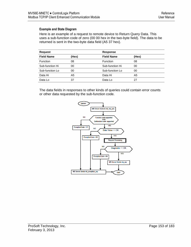
MVI56E-MNETC ♦ ControlLogix Platform Reference Modbus TCP/IP Client Enhanced Communication Module User Manual
ProSoft Technology, Inc. Page 153 of 183 February 3, 2013
Example and State Diagram
Here is an example of a request to remote device to Return Query Data. This uses a sub-function code of zero (00 00 hex in the two-byte field). The data to be returned is sent in the two-byte data field (A5 37 hex).
Request Response
Field Name (Hex) Field Name (Hex)
Function 08 Function 08
Sub-function Hi 00 Sub-function Hi 00
Sub-function Lo 00 Sub-function Lo 00
Data Hi A5 Data Hi A5
Data Lo 37 Data Lo 27
The data fields in responses to other kinds of queries could contain error counts or other data requested by the sub-function code.

Guide to the MVI56E-MNETC User Manual MVI56E-MNETC ♦ ControlLogix Platform User Manual Modbus TCP/IP Client Enhanced Communication Module
Page 154 of 183 ProSoft Technology, Inc. February 3, 2013
5.5.10 Force Multiple Coils (Function Code 15)
Query
This message forces each coil in a consecutive block of coils to a desired ON or OFF state. Any coil that exists within the controller can be forced to either state (ON or OFF). However, because the controller is actively scanning, unless the coils are disabled, the controller can also alter the state of the coil. Coils are numbered from zero (coil 00001 = zero, coil 00002 = one, and so on). The desired status of each coil is packed in the data field, one bit for each coil (1= ON, 0= OFF). The use of server address 0 (Broadcast Mode) will force all attached servers to modify the desired coils.
Note: Functions 5, 6, 15, and 16 are the only messages (other than Loopback Diagnostic Test) that will be recognized as valid for broadcast.
The following example forces 10 coils starting at address 20 (13 HEX). The two data fields, CD =1100 and 00 = 0000 000, indicate that coils 27, 26, 23, 22, and 20 are to be forced on.
Adr Func Hi Add Lo Add
Quantity Byte Cnt
Data Coil Status 20 to 27
Data Coil Status 28 to 29
Error Check Field
11 0F 00 13 00 0A 02 CD 00 CRC
Response
The normal response will be an echo of the server address, function code, starting address, and quantity of coils forced.
Adr Func Hi Addr Lo Addr Quantity Error Check Field
11 0F 00 13 00 0A CRC
The writing of coils via Modbus function 15 will be accomplished regardless of whether the addressed coils are disabled or not.
Coils that are unprogrammed in the controller logic program are not automatically cleared upon power up. Thus, if such a coil is set ON by function code 15 and (even months later) an output is connected to that coil, the output will be hot.
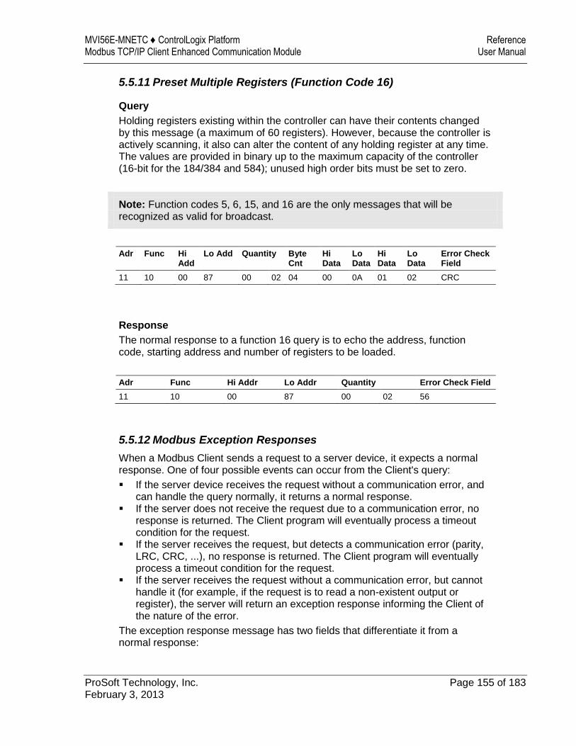
MVI56E-MNETC ♦ ControlLogix Platform Reference Modbus TCP/IP Client Enhanced Communication Module User Manual
ProSoft Technology, Inc. Page 155 of 183 February 3, 2013
5.5.11 Preset Multiple Registers (Function Code 16)
Query
Holding registers existing within the controller can have their contents changed by this message (a maximum of 60 registers). However, because the controller is actively scanning, it also can alter the content of any holding register at any time. The values are provided in binary up to the maximum capacity of the controller (16-bit for the 184/384 and 584); unused high order bits must be set to zero.
Note: Function codes 5, 6, 15, and 16 are the only messages that will be recognized as valid for broadcast.
Adr Func Hi Add
Lo Add Quantity Byte Cnt
Hi Data
Lo Data
Hi Data
Lo Data
Error Check Field
11 10 00 87 00 02 04 00 0A 01 02 CRC
Response
The normal response to a function 16 query is to echo the address, function code, starting address and number of registers to be loaded.
Adr Func Hi Addr Lo Addr Quantity Error Check Field
11 10 00 87 00 02 56
5.5.12 Modbus Exception Responses
When a Modbus Client sends a request to a server device, it expects a normal response. One of four possible events can occur from the Client's query:
If the server device receives the request without a communication error, and can handle the query normally, it returns a normal response.
If the server does not receive the request due to a communication error, no response is returned. The Client program will eventually process a timeout condition for the request.
If the server receives the request, but detects a communication error (parity, LRC, CRC, ...), no response is returned. The Client program will eventually process a timeout condition for the request.
If the server receives the request without a communication error, but cannot handle it (for example, if the request is to read a non-existent output or register), the server will return an exception response informing the Client of the nature of the error.
The exception response message has two fields that differentiate it from a normal response:
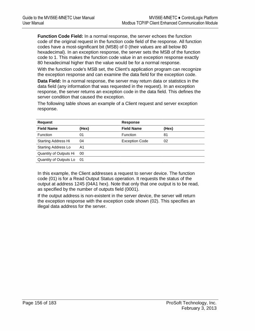
Guide to the MVI56E-MNETC User Manual MVI56E-MNETC ♦ ControlLogix Platform User Manual Modbus TCP/IP Client Enhanced Communication Module
Page 156 of 183 ProSoft Technology, Inc. February 3, 2013
Function Code Field: In a normal response, the server echoes the function code of the original request in the function code field of the response. All function codes have a most-significant bit (MSB) of 0 (their values are all below 80 hexadecimal). In an exception response, the server sets the MSB of the function code to 1. This makes the function code value in an exception response exactly 80 hexadecimal higher than the value would be for a normal response.
With the function code's MSB set, the Client's application program can recognize the exception response and can examine the data field for the exception code.
Data Field: In a normal response, the server may return data or statistics in the data field (any information that was requested in the request). In an exception response, the server returns an exception code in the data field. This defines the server condition that caused the exception.
The following table shows an example of a Client request and server exception response.
Request Response
Field Name (Hex) Field Name (Hex)
Function 01 Function 81
Starting Address Hi 04 Exception Code 02
Starting Address Lo A1
Quantity of Outputs Hi 00
Quantity of Outputs Lo 01
In this example, the Client addresses a request to server device. The function code (01) is for a Read Output Status operation. It requests the status of the output at address 1245 (04A1 hex). Note that only that one output is to be read, as specified by the number of outputs field (0001).
If the output address is non-existent in the server device, the server will return the exception response with the exception code shown (02). This specifies an illegal data address for the server.

MVI56E-MNETC ♦ ControlLogix Platform Reference Modbus TCP/IP Client Enhanced Communication Module User Manual
ProSoft Technology, Inc. Page 157 of 183 February 3, 2013
Modbus Exception Codes
Code Name Meaning
01 Illegal Function The function code received in the query is not an allowable action for the server. This may be because the function code is only applicable to newer devices, and was not implemented in the unit selected. It could also indicate that the server is in the wrong state to process a request of this type, for example because it is not configured and is being asked to return register values.
02 Illegal Data Address The data address received in the query is not an allowable address for the server. More specifically, the combination of reference number and transfer length is invalid. For a controller with 100 registers, a request with offset 96 and length 4 would succeed; a request with offset 96 and length 5 will generate exception 02.
03 Illegal Data Value A value contained in the query data field is not an allowable value for server. This indicates a fault in the structure of the remainder of a complex request, such as that the implied length is incorrect. It specifically does not mean that a data item submitted for storage in a register has a value outside the expectation of the application program, because the Modbus protocol is unaware of the significance of any particular value of any particular register.
04 Slave Device Failure An unrecoverable error occurred while the server was attempting to perform the requested action.
05 Acknowledge Specialized use in conjunction with programming commands. The server has accepted the request and is processing it, but a long duration of time will be required to do so. This response is returned to prevent a timeout error from occurring in the Client. The Client can next issue a poll program complete message to determine if processing is completed.
06 Slave Device Busy Specialized use in conjunction with programming commands. The server is engaged in processing a long-duration program command. The Client should retransmit the message later when the server is free.
08 Memory Parity Error Specialized use in conjunction with function codes 20 and 21 and reference type 6, to indicate that the extended file area failed to pass a consistency check. The server attempted to read record file, but detected a parity error in the memory. The Client can retry the request, but service may be required on the server device.
0a Gateway Path Unavailable Specialized use in conjunction with gateways, indicates that the gateway was unable to allocate an internal communication path from the input port to the output port for processing the request. Usually means that the gateway is misconfigured or overloaded.
0b Gateway Target Device Failed To Respond
Specialized use in conjunction with gateways, indicates that no response was obtained from the target device. Usually means that the device is not present on the network.
Guide to the MVI56E-MNETC User Manual MVI56E-MNETC ♦ ControlLogix Platform User Manual Modbus TCP/IP Client Enhanced Communication Module
Page 158 of 183 ProSoft Technology, Inc. February 3, 2013
5.6 Using the Optional Add-On Instruction Rung Import
5.6.1 Before You Begin
Make sure that you have installed RSLogix 5000 version 16 (or later). Download the Optional Add-On file
MVI56EMNETC_Optional_AddOn_Rung_v1_0.L5X from www.prosoft-technology.com or copy it from the ProSoft Solutions CD-ROM.
Save a copy in a folder in your PC.
5.6.2 Overview
The Optional Add-On Instruction Rung Import contains optional logic for MVI56E-MNETC applications to perform the following tasks.
Read/Write Ethernet Configuration
Allows the processor to read or write the module IP address, netmask and gateway values.
Note: This is an optional feature. You can perform the same task through PCB (ProSoft Configuration Builder). Even if your PC is in a different network group you can still access the module through PCB by setting a temporary IP address.
Read/Write Module Clock Value
Allows the processor to read and write the module clock settings. The module clock stores the last time that the Ethernet configuration was changed. The date and time of the last Ethernet configuration change is displayed in the scrolling LED during module power up.
Important: The Optional Add-On Instruction only supports the two features listed above. You must use the sample ladder logic for all other features including backplane transfer of Modbus TCP/IP data.
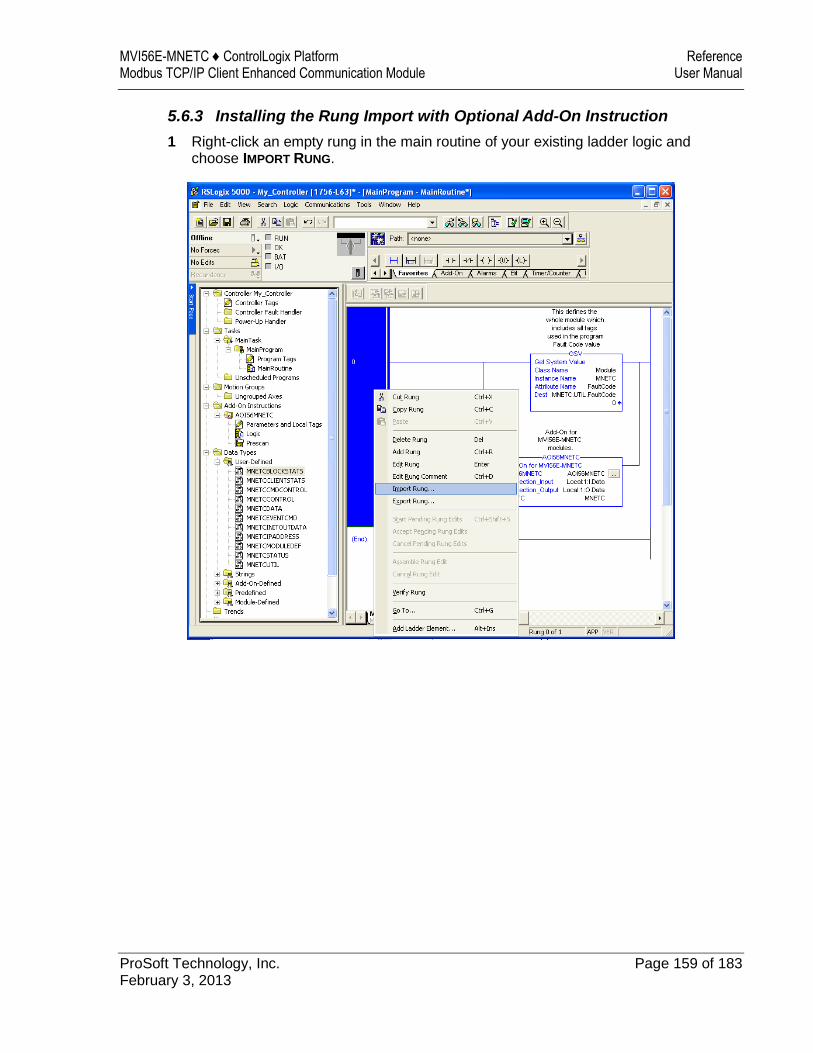
MVI56E-MNETC ♦ ControlLogix Platform Reference Modbus TCP/IP Client Enhanced Communication Module User Manual
ProSoft Technology, Inc. Page 159 of 183 February 3, 2013
5.6.3 Installing the Rung Import with Optional Add-On Instruction
1 Right-click an empty rung in the main routine of your existing ladder logic and choose IMPORT RUNG.
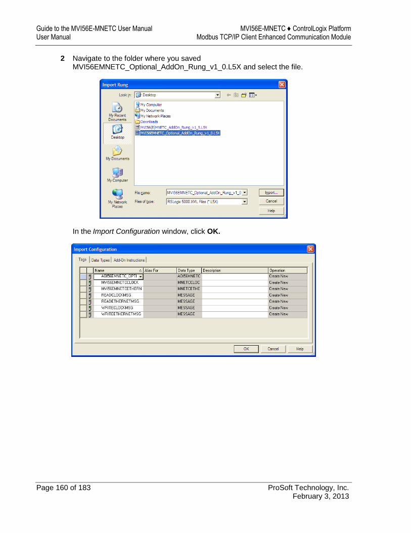
Guide to the MVI56E-MNETC User Manual MVI56E-MNETC ♦ ControlLogix Platform User Manual Modbus TCP/IP Client Enhanced Communication Module
Page 160 of 183 ProSoft Technology, Inc. February 3, 2013
2 Navigate to the folder where you saved MVI56EMNETC_Optional_AddOn_Rung_v1_0.L5X and select the file.
In the Import Configuration window, click OK.
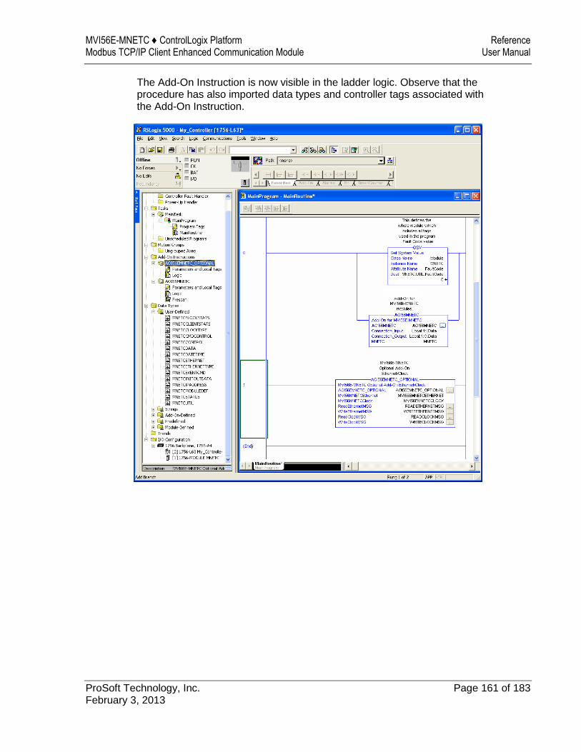
MVI56E-MNETC ♦ ControlLogix Platform Reference Modbus TCP/IP Client Enhanced Communication Module User Manual
ProSoft Technology, Inc. Page 161 of 183 February 3, 2013
The Add-On Instruction is now visible in the ladder logic. Observe that the procedure has also imported data types and controller tags associated with the Add-On Instruction.
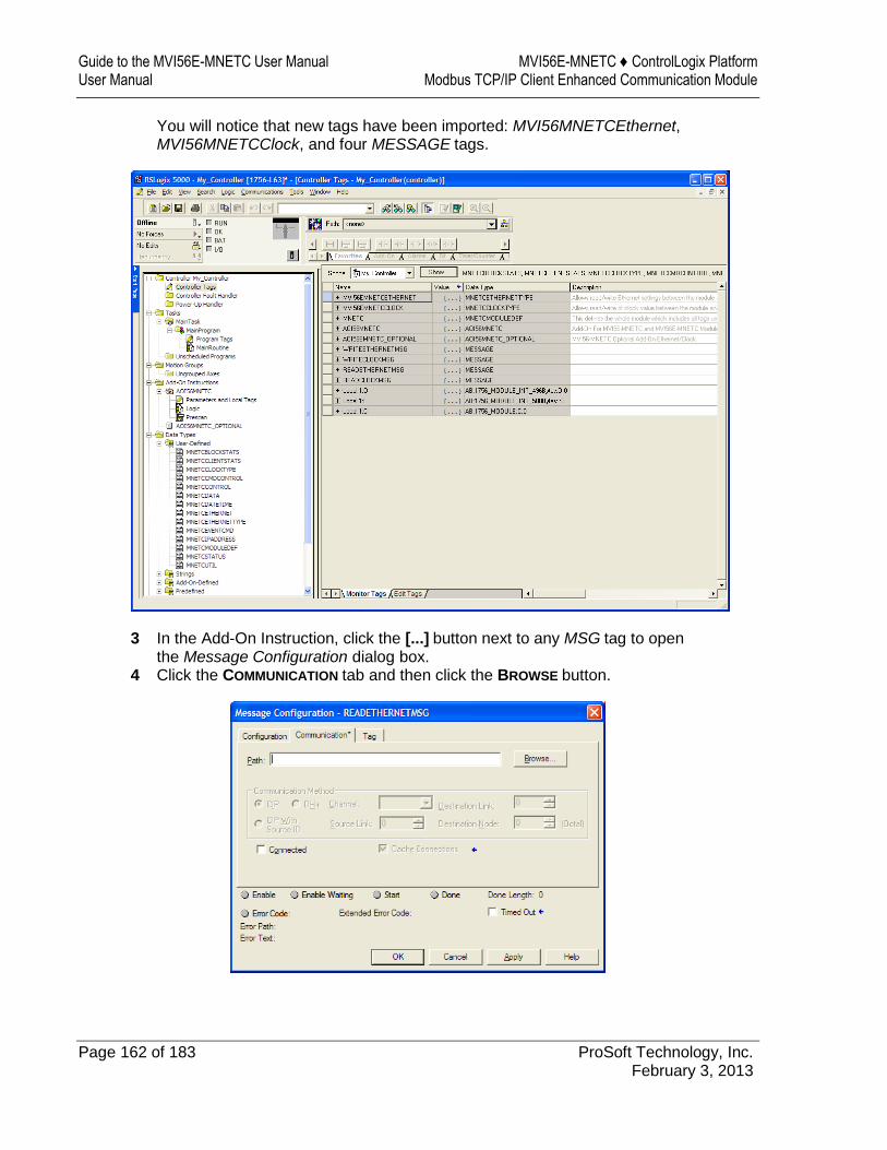
Guide to the MVI56E-MNETC User Manual MVI56E-MNETC ♦ ControlLogix Platform User Manual Modbus TCP/IP Client Enhanced Communication Module
Page 162 of 183 ProSoft Technology, Inc. February 3, 2013
You will notice that new tags have been imported: MVI56MNETCEthernet, MVI56MNETCClock, and four MESSAGE tags.
3 In the Add-On Instruction, click the [...] button next to any MSG tag to open the Message Configuration dialog box.
4 Click the COMMUNICATION tab and then click the BROWSE button.
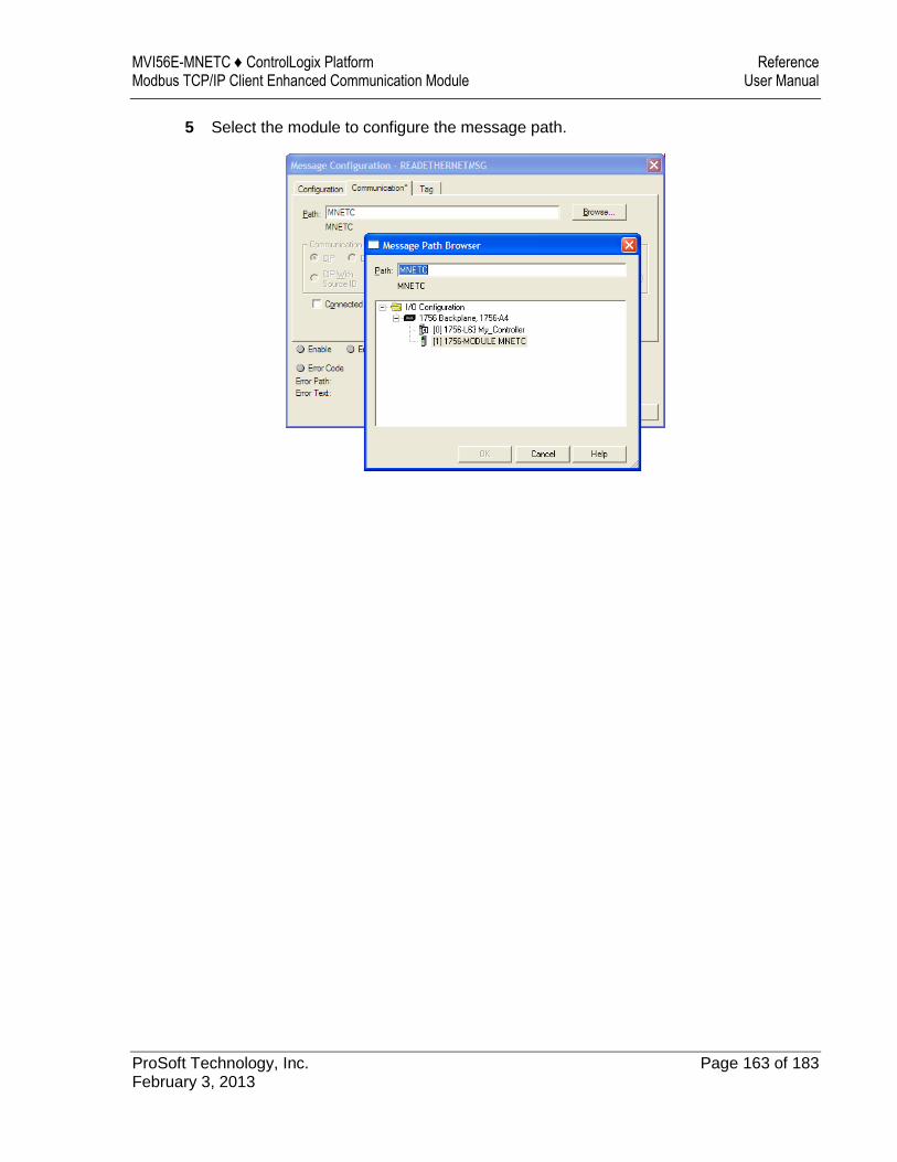
MVI56E-MNETC ♦ ControlLogix Platform Reference Modbus TCP/IP Client Enhanced Communication Module User Manual
ProSoft Technology, Inc. Page 163 of 183 February 3, 2013
5 Select the module to configure the message path.
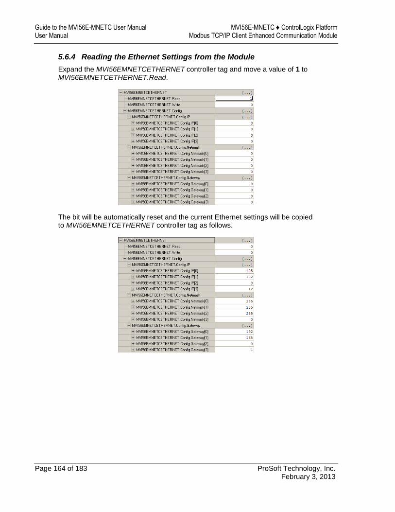
Guide to the MVI56E-MNETC User Manual MVI56E-MNETC ♦ ControlLogix Platform User Manual Modbus TCP/IP Client Enhanced Communication Module
Page 164 of 183 ProSoft Technology, Inc. February 3, 2013
5.6.4 Reading the Ethernet Settings from the Module
Expand the MVI56EMNETCETHERNET controller tag and move a value of 1 to MVI56EMNETCETHERNET.Read.
The bit will be automatically reset and the current Ethernet settings will be copied to MVI56EMNETCETHERNET controller tag as follows.
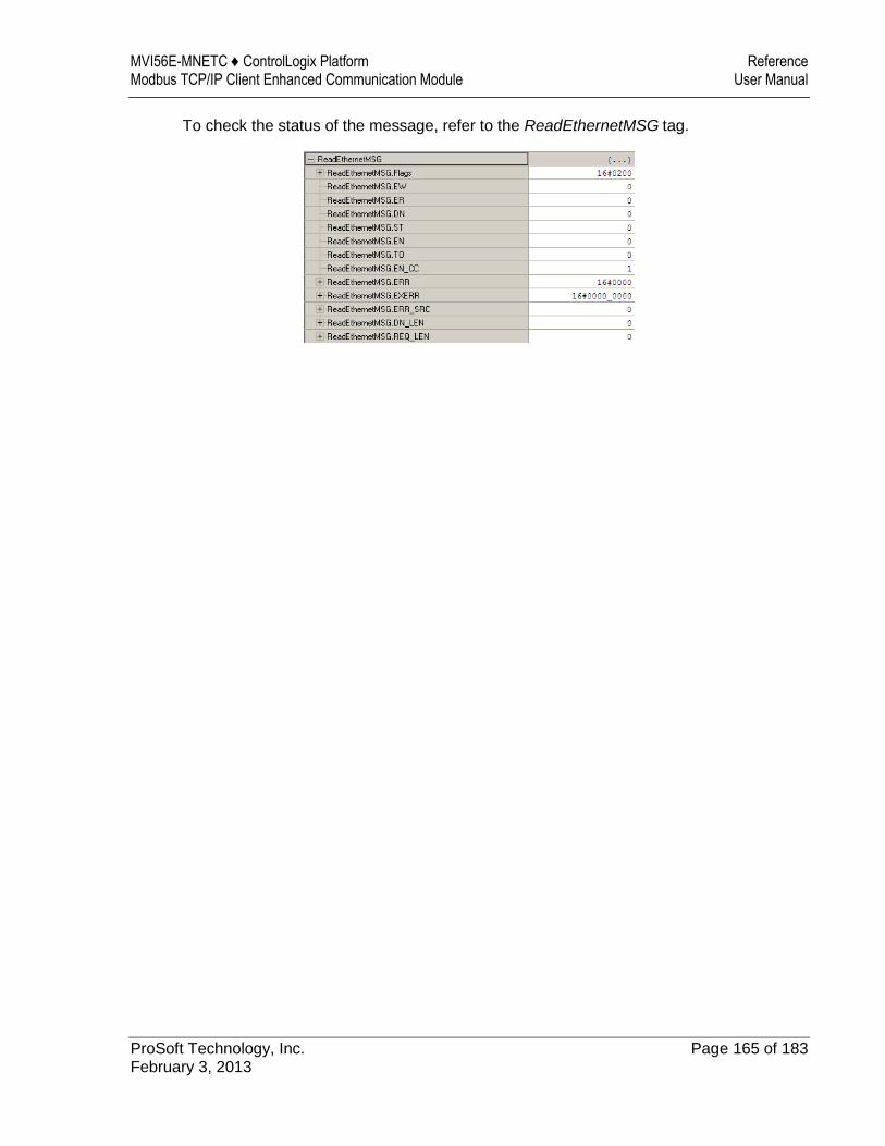
MVI56E-MNETC ♦ ControlLogix Platform Reference Modbus TCP/IP Client Enhanced Communication Module User Manual
ProSoft Technology, Inc. Page 165 of 183 February 3, 2013
To check the status of the message, refer to the ReadEthernetMSG tag.
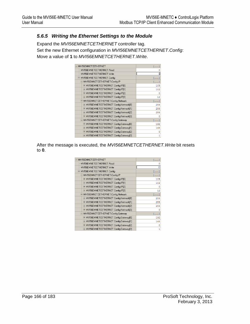
Guide to the MVI56E-MNETC User Manual MVI56E-MNETC ♦ ControlLogix Platform User Manual Modbus TCP/IP Client Enhanced Communication Module
Page 166 of 183 ProSoft Technology, Inc. February 3, 2013
5.6.5 Writing the Ethernet Settings to the Module
Expand the MVI56EMNETCETHERNET controller tag.
Set the new Ethernet configuration in MVI56EMNETCETHERNET.Config:
Move a value of 1 to MVI56EMNETCETHERNET.Write.
After the message is executed, the MVI56EMNETCETHERNET.Write bit resets to 0.
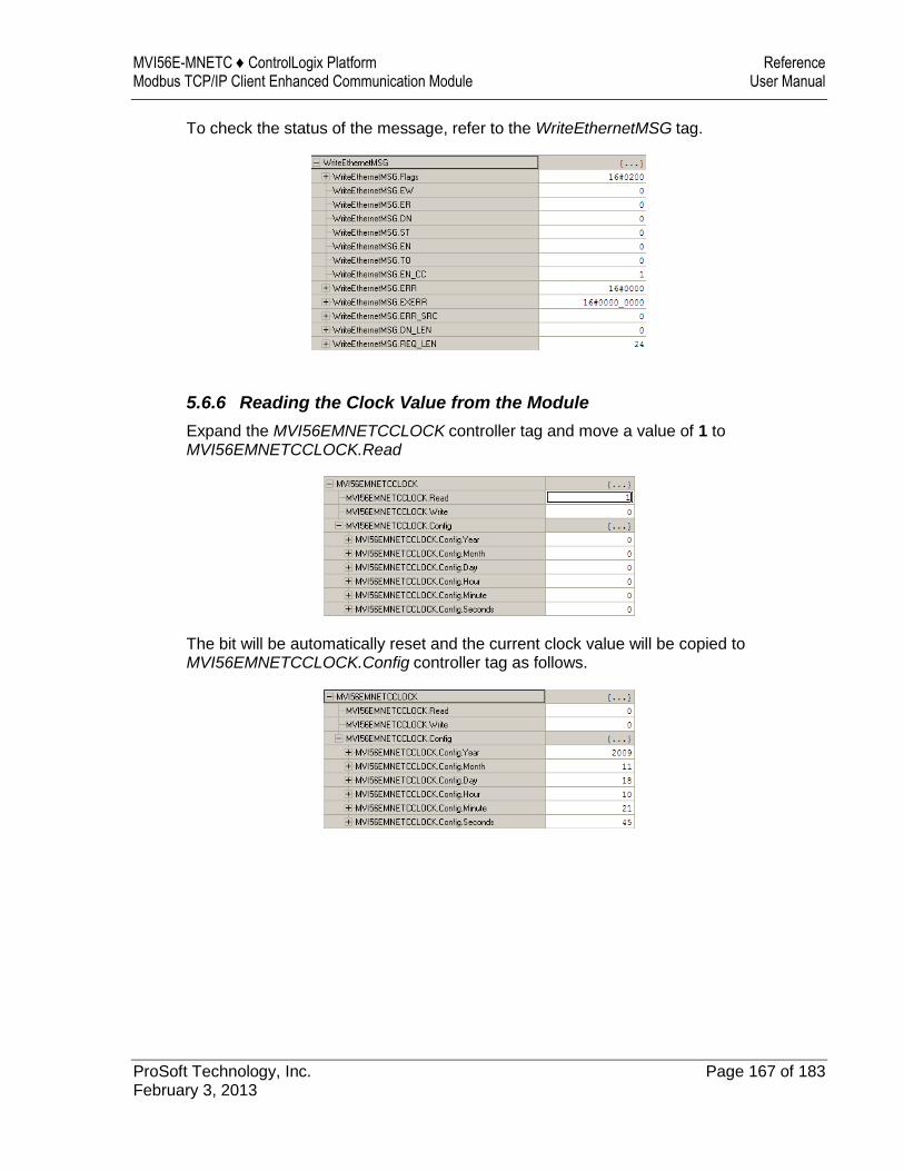
MVI56E-MNETC ♦ ControlLogix Platform Reference Modbus TCP/IP Client Enhanced Communication Module User Manual
ProSoft Technology, Inc. Page 167 of 183 February 3, 2013
To check the status of the message, refer to the WriteEthernetMSG tag.
5.6.6 Reading the Clock Value from the Module
Expand the MVI56EMNETCCLOCK controller tag and move a value of 1 to MVI56EMNETCCLOCK.Read
The bit will be automatically reset and the current clock value will be copied to MVI56EMNETCCLOCK.Config controller tag as follows.
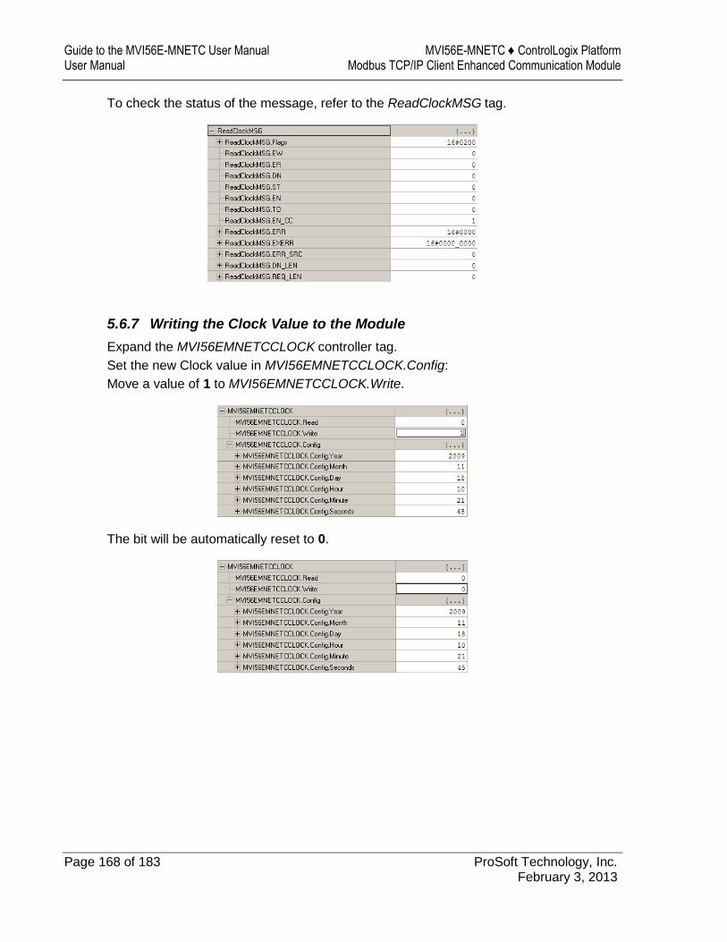
Guide to the MVI56E-MNETC User Manual MVI56E-MNETC ♦ ControlLogix Platform User Manual Modbus TCP/IP Client Enhanced Communication Module
Page 168 of 183 ProSoft Technology, Inc. February 3, 2013
To check the status of the message, refer to the ReadClockMSG tag.
5.6.7 Writing the Clock Value to the Module
Expand the MVI56EMNETCCLOCK controller tag.
Set the new Clock value in MVI56EMNETCCLOCK.Config:
Move a value of 1 to MVI56EMNETCCLOCK.Write.
The bit will be automatically reset to 0.
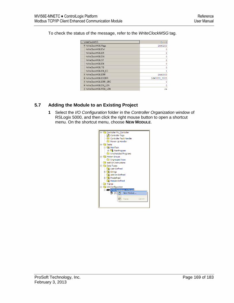
MVI56E-MNETC ♦ ControlLogix Platform Reference Modbus TCP/IP Client Enhanced Communication Module User Manual
ProSoft Technology, Inc. Page 169 of 183 February 3, 2013
To check the status of the message, refer to the WriteClockMSG tag.
5.7 Adding the Module to an Existing Project
1 Select the I/O Configuration folder in the Controller Organization window of RSLogix 5000, and then click the right mouse button to open a shortcut menu. On the shortcut menu, choose NEW MODULE.
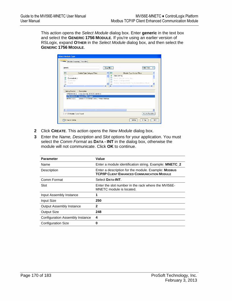
Guide to the MVI56E-MNETC User Manual MVI56E-MNETC ♦ ControlLogix Platform User Manual Modbus TCP/IP Client Enhanced Communication Module
Page 170 of 183 ProSoft Technology, Inc. February 3, 2013
This action opens the Select Module dialog box. Enter generic in the text box and select the GENERIC 1756 MODULE. If you're using an earlier version of RSLogix, expand OTHER in the Select Module dialog box, and then select the GENERIC 1756 MODULE.
2 Click CREATE. This action opens the New Module dialog box.
3 Enter the Name, Description and Slot options for your application. You must select the Comm Format as DATA - INT in the dialog box, otherwise the module will not communicate. Click OK to continue.
Parameter Value
Name Enter a module identification string. Example: MNETC_2
Description Enter a description for the module. Example: MODBUS
TCP/IP CLIENT ENHANCED COMMUNICATION MODULE
Comm Format Select DATA-INT.
Slot Enter the slot number in the rack where the MVI56E-MNETC module is located.
Input Assembly Instance 1
Input Size 250
Output Assembly Instance 2
Output Size 248
Configuration Assembly Instance 4
Configuration Size 0
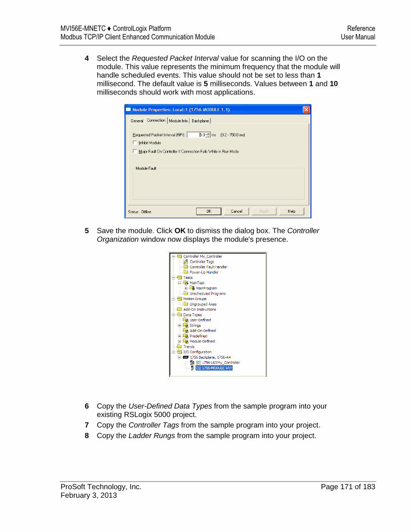
MVI56E-MNETC ♦ ControlLogix Platform Reference Modbus TCP/IP Client Enhanced Communication Module User Manual
ProSoft Technology, Inc. Page 171 of 183 February 3, 2013
4 Select the Requested Packet Interval value for scanning the I/O on the module. This value represents the minimum frequency that the module will handle scheduled events. This value should not be set to less than 1 millisecond. The default value is 5 milliseconds. Values between 1 and 10 milliseconds should work with most applications.
5 Save the module. Click OK to dismiss the dialog box. The Controller Organization window now displays the module's presence.
6 Copy the User-Defined Data Types from the sample program into your existing RSLogix 5000 project.
7 Copy the Controller Tags from the sample program into your project.
8 Copy the Ladder Rungs from the sample program into your project.

Guide to the MVI56E-MNETC User Manual MVI56E-MNETC ♦ ControlLogix Platform User Manual Modbus TCP/IP Client Enhanced Communication Module
Page 172 of 183 ProSoft Technology, Inc. February 3, 2013
5.8 Using the Sample Program
If your processor uses RSLogix 5000 version 15 or earlier, you will not be able to use the Add-On Instruction for your module. Follow the steps below to obtain and use a sample program for your application.
5.8.1 Opening the Sample Program in RSLogix
The sample program for your MVI56E-MNETC module includes custom tags, data types and ladder logic for data I/O, status and command control. For most applications, you can run the sample program without modification, or, for advanced applications, you can incorporate the sample program into your existing application.
Download the manuals and sample program from the ProSoft Technology web site
You can always download the latest version of the sample ladder logic and user manuals for the MVI56E-MNETC module from the ProSoft Technology website, at www.prosoft-technology.com/support/downloads (http://www.prosoft-technology.com/support/downloads)
From that link, navigate to the download page for your module and choose the sample program to download for your version of RSLogix 5000 and your processor.
To determine the firmware version of your processor
Important: The RSLinx service must be installed and running on your computer in order for RSLogix to communicate with the processor. Refer to your RSLinx and RSLogix documentation for help configuring and troubleshooting these applications.
1 Connect an RS-232 serial cable from the COM (serial) port on your PC to the communication port on the front of the processor.
2 Start RSLogix 5000 and close any existing project that may be loaded. 3 Open the COMMUNICATIONS menu and choose GO ONLINE. RSLogix will
establish communication with the processor. This may take a few moments.
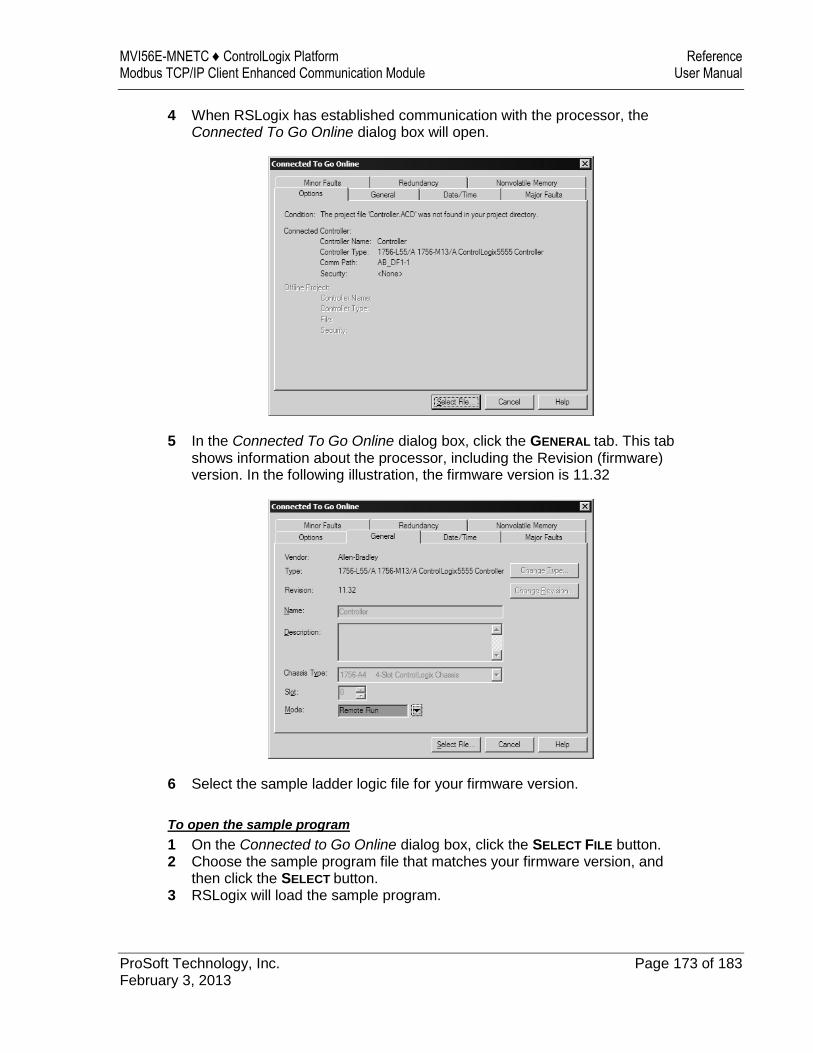
MVI56E-MNETC ♦ ControlLogix Platform Reference Modbus TCP/IP Client Enhanced Communication Module User Manual
ProSoft Technology, Inc. Page 173 of 183 February 3, 2013
4 When RSLogix has established communication with the processor, the Connected To Go Online dialog box will open.
5 In the Connected To Go Online dialog box, click the GENERAL tab. This tab shows information about the processor, including the Revision (firmware) version. In the following illustration, the firmware version is 11.32
6 Select the sample ladder logic file for your firmware version.
To open the sample program
1 On the Connected to Go Online dialog box, click the SELECT FILE button. 2 Choose the sample program file that matches your firmware version, and
then click the SELECT button. 3 RSLogix will load the sample program.
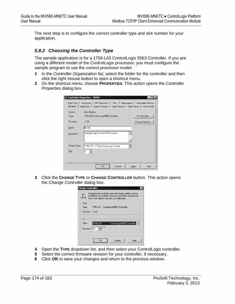
Guide to the MVI56E-MNETC User Manual MVI56E-MNETC ♦ ControlLogix Platform User Manual Modbus TCP/IP Client Enhanced Communication Module
Page 174 of 183 ProSoft Technology, Inc. February 3, 2013
The next step is to configure the correct controller type and slot number for your application.
5.8.2 Choosing the Controller Type
The sample application is for a 1756-L63 ControlLogix 5563 Controller. If you are using a different model of the ControlLogix processor, you must configure the sample program to use the correct processor model.
1 In the Controller Organization list, select the folder for the controller and then click the right mouse button to open a shortcut menu.
2 On the shortcut menu, choose PROPERTIES. This action opens the Controller Properties dialog box.
3 Click the CHANGE TYPE or CHANGE CONTROLLER button. This action opens the Change Controller dialog box.
4 Open the TYPE dropdown list, and then select your ControlLogix controller. 5 Select the correct firmware revision for your controller, if necessary. 6 Click OK to save your changes and return to the previous window.
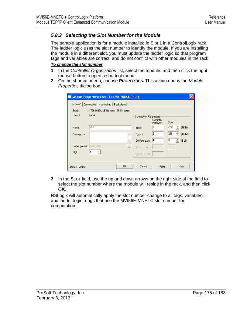
MVI56E-MNETC ♦ ControlLogix Platform Reference Modbus TCP/IP Client Enhanced Communication Module User Manual
ProSoft Technology, Inc. Page 175 of 183 February 3, 2013
5.8.3 Selecting the Slot Number for the Module
The sample application is for a module installed in Slot 1 in a ControlLogix rack. The ladder logic uses the slot number to identify the module. If you are installing the module in a different slot, you must update the ladder logic so that program tags and variables are correct, and do not conflict with other modules in the rack.
To change the slot number
1 In the Controller Organization list, select the module, and then click the right mouse button to open a shortcut menu.
2 On the shortcut menu, choose PROPERTIES. This action opens the Module Properties dialog box.
3 In the SLOT field, use the up and down arrows on the right side of the field to select the slot number where the module will reside in the rack, and then click OK.
RSLogix will automatically apply the slot number change to all tags, variables and ladder logic rungs that use the MVI56E-MNETC slot number for computation.
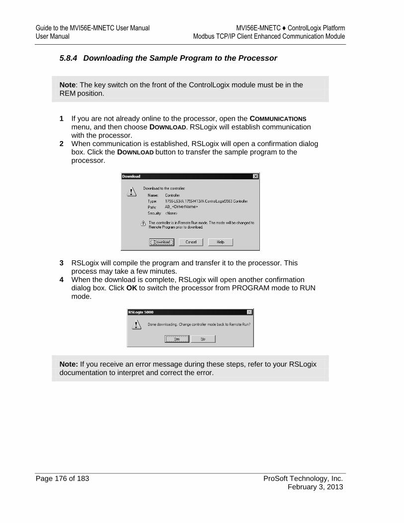
Guide to the MVI56E-MNETC User Manual MVI56E-MNETC ♦ ControlLogix Platform User Manual Modbus TCP/IP Client Enhanced Communication Module
Page 176 of 183 ProSoft Technology, Inc. February 3, 2013
5.8.4 Downloading the Sample Program to the Processor
Note: The key switch on the front of the ControlLogix module must be in the REM position.
1 If you are not already online to the processor, open the COMMUNICATIONS
menu, and then choose DOWNLOAD. RSLogix will establish communication with the processor.
2 When communication is established, RSLogix will open a confirmation dialog box. Click the DOWNLOAD button to transfer the sample program to the processor.
3 RSLogix will compile the program and transfer it to the processor. This process may take a few minutes.
4 When the download is complete, RSLogix will open another confirmation dialog box. Click OK to switch the processor from PROGRAM mode to RUN mode.
Note: If you receive an error message during these steps, refer to your RSLogix documentation to interpret and correct the error.

MVI56E-MNETC ♦ ControlLogix Platform Reference Modbus TCP/IP Client Enhanced Communication Module User Manual
ProSoft Technology, Inc. Page 177 of 183 February 3, 2013
5.8.5 Adding the Sample Ladder to an Existing Application
1 Copy the Controller Tags (page 78) from the sample program. 2 Copy the User-Defined Data Types (page 80) from the sample program. 3 Copy the Ladder Rungs from the sample program. 4 Save and Download (page 35, page 176) the new application to the controller
and place the processor in RUN mode.

Guide to the MVI56E-MNETC User Manual MVI56E-MNETC ♦ ControlLogix Platform User Manual Modbus TCP/IP Client Enhanced Communication Module
Page 178 of 183 ProSoft Technology, Inc. February 3, 2013
MVI56E-MNETC ♦ ControlLogix Platform Support, Service & Warranty Modbus TCP/IP Client Enhanced Communication Module User Manual
ProSoft Technology, Inc. Page 179 of 183 February 3, 2013
6 Support, Service & Warranty
In This Chapter
Contacting Technical Support ............................................................. 179
Warranty Information ........................................................................... 180
Contacting Technical Support
ProSoft Technology, Inc. (ProSoft) is committed to providing the most efficient and effective support possible. Before calling, please gather the following information to assist in expediting this process:
1 Product Version Number 2 System architecture 3 Network details
If the issue is hardware related, we will also need information regarding:
1 Module configuration and associated ladder files, if any 2 Module operation and any unusual behavior 3 Configuration/Debug status information 4 LED patterns 5 Details about the serial, Ethernet or fieldbus devices interfaced to the module,
if any.
Note: For technical support calls within the United States, an after-hours answering system allows 24-hour/7-days-a-week pager access to one of our qualified Technical and/or Application Support Engineers. Detailed contact information for all our worldwide locations is available on the following page.
Guide to the MVI56E-MNETC User Manual MVI56E-MNETC ♦ ControlLogix Platform User Manual Modbus TCP/IP Client Enhanced Communication Module
Page 180 of 183 ProSoft Technology, Inc. February 3, 2013
Internet Web Site: www.prosoft-technology.com/support
E-mail address: [email protected]
Asia Pacific
(location in Malaysia)
Tel: +603.7724.2080, E-mail: [email protected]
Languages spoken include: Chinese, English
Asia Pacific
(location in China)
Tel: +86.21.5187.7337 x888, E-mail: [email protected]
Languages spoken include: Chinese, English
Europe
(location in Toulouse, France)
Tel: +33 (0) 5.34.36.87.20,
E-mail: [email protected]
Languages spoken include: French, English
Europe
(location in Dubai, UAE)
Tel: +971-4-214-6911,
E-mail: [email protected]
Languages spoken include: English, Hindi
North America
(location in California)
Tel: +1.661.716.5100,
E-mail: [email protected]
Languages spoken include: English, Spanish
Latin America
(Oficina Regional)
Tel: +1-281-2989109,
E-Mail: [email protected]
Languages spoken include: Spanish, English
Latin America
(location in Puebla, Mexico)
Tel: +52-222-3-99-6565,
E-mail: [email protected]
Languages spoken include: Spanish
Brasil
(location in Sao Paulo)
Tel: +55-11-5083-3776,
E-mail: [email protected]
Languages spoken include: Portuguese, English
6.1 Warranty Information
For complete details regarding ProSoft Technology’s TERMS & CONDITIONS OF SALE, WARRANTY, SUPPORT, SERVICE AND RETURN MATERIAL AUTHORIZATION INSTRUCTIONS please see the documents on the Product CD/DVD or go to www.prosoft-technology/warranty
Documentation is subject to change without notice

MVI56E-MNETC ♦ ControlLogix Platform Index Modbus TCP/IP Client Enhanced Communication Module User Manual
ProSoft Technology, Inc. Page 181 of 183 February 3, 2013
Index
0
00 Return Query Data • 152
A
About the MODBUS TCP/IP Protocol • 145 Adding Multiple Modules (Optional) • 27 Adding the Module to an Existing Project • 169 Adding the Sample Ladder to an Existing Application •
177 Adjusting the Input and Output Array Sizes • 32 ARP Timeout • 50
B
Backplane Data Transfer • 112 Backplane Error/Status Pointer • 43, 101 Backplane Status • 97 Battery Life Advisory • 4 Before You Begin • 158 Bit Input Offset • 48 Block 4200 • 128 Blocks 4000 to 4029 • 124 Blocks 4100 to 4129 • 127
C
Choosing the Controller Type • 174 Clearing a Fault Condition • 91 Client Command Errors • 100, 106, 142 Client Command List • 142 Client Driver • 141 Client Error/Status Pointer • 49, 101 Client Status Blocks (3000 to 3029) • 49, 101, 102, 122 Cold Boot Block (9999) • 137 Command Control Blocks (5001-5016) • 54, 129 Command Entry Formats • 53 Command Error Delay • 51 Command Error Pointer • 49, 101 Command List • 99 Command List Entry Errors • 107 Command List Overview • 52 Command Status • 100 Commands Supported by the Module • 52 Comment • 58 Config • 96, 99 Configuration Error Word • 105 Configuring Module Parameters • 42 Configuring the MVI56E-MNETC Module • 37 Connecting to the Module's Web Page • 94 Connecting Your PC to the ControlLogix Processor •
34 Connecting Your PC to the Module • 61 Connection Timeout • 48
Contacting Technical Support • 179 Controller Tag Overview • 82 Controller Tags • 78, 177 Creating a New RSLogix 5000 Project • 19 Creating the Module • 20
D
Data Flow between MVI56E-MNETC Module and Processor • 138
Diagnostics (Function Code 08) • 152 Diagnostics and Troubleshooting • 9, 87, 88 Downloading the Project to the Module • 33, 65 Downloading the Sample Program to the Processor •
35, 176, 177 Duplex/Speed Code • 45
E
Enable • 54 Ethernet Cable Configuration • 143 Ethernet Cable Specifications • 143 Ethernet Configuration • 60, 63 Ethernet LED Indicators • 89 Ethernet Performance • 144 Event Command Blocks (2000 to 2029) • 119 Event Command Blocks with Sequence Number (4000
to 4029, 4100 to 4129, and 4200) • 124 Example 1
Local Rack Application • 68 Example 2
Remote Rack Application • 71 Example and State Diagram • 153
F
Failure Flag Count • 45 Float Flag • 46, 50 Float Offset • 47, 50 Float Start • 47, 50 Force Multiple Coils (Function Code 15) • 154 Force Single Coil (Function Code 05) • 150 Formatted Pass-Through Blocks (9956 to 9961, 9970)
• 132 Functional Specifications • 111
G
General Specifications • 110 Get Module IP Address Block (9991) • 135 Guide to the MVI56E-MNETC User Manual • 9
H
Hardware MAC Address • 59 Hardware Specifications • 111 Holding Register Offset • 48 How to Contact Us • 2
I
Important Safety Information • 3 Importing the Add-On Instruction • 23
Index MVI56E-MNETC ♦ ControlLogix Platform User Manual Modbus TCP/IP Client Enhanced Communication Module
Page 182 of 183 ProSoft Technology, Inc. February 3, 2013
Importing the Sample Add-On Instruction • 18, 25 Initialize Output Data • 45 Initialize Output Data Blocks (1000 to 1049) • 118 Installing ProSoft Configuration Builder • 38 Installing the Module in the Rack • 16 Installing the Rung Import with Optional Add-On
Instruction • 159 Internal Address • 55 IP Address • 59
L
Ladder Logic • 77 LED Status Indicators • 88
M
MB Address in Device • 58 MBAP Port Override • 51 Minimum Command Delay • 49 MNET Client Specific Errors • 107 MNET Client x • 48 MNET Client x Commands • 51, 119, 124, 129 MNET Servers • 46, 99 MNETC.CONTROL • 85 MNETC.DATA • 82 MNETC.STATUS • 85 MNETC.UTIL • 86 Modbus Exception Codes • 157 Modbus Exception Responses • 155 Modbus Function • 57 Modbus Protocol Specification • 145 Modbus TCP/IP Client (Master) • 111 Modbus TCP/IP Specifications • 110 Module • 43 Module Communication Error Codes • 107 Monitoring Backplane Information • 96 Monitoring Database Information • 98 Monitoring MNET Client Information • 99 Monitoring MNET Server Information • 99 Monitoring Module Information • 96 MVI56E-MNETC Controller Tags • 78 MVI56E-MNETC User-Defined Data Types • 80
N
NIC Status • 96 Node IP Address • 56, 57 Non-Scrolling LED Status Indicators • 89 Normal Data Transfer Blocks • 43, 101, 102, 114
O
Opening the Sample Program in RSLogix • 172 Output Offset • 47 Overview • 158
P
Package Contents • 14 Pass-Through Blocks (9956 to 9961, 9970, 9996) •
131 Pass-Through Mode • 45
Pinouts • 111, 143 Poll Interval • 55 Preset Multiple Registers (Function Code 16) • 155 Preset Single Register (Function Code 06) • 151 Printing a Configuration File • 43 Product Specifications • 9, 110 ProSoft Discovery Service • 61, 63, 94
R
Read Block • 114 Read Coil Status (Function Code 01) • 146 Read Exception Status (Function Code 07) • 152 Read Holding Registers (Function Code 03) • 148 Read Input Registers (Function Code 04) • 149 Read Input Status (Function Code 02) • 147 Read Register Count • 44, 83 Read Register Start • 43 Reading Status Data from the Module • 101 Reading the Clock Value from the Module • 167 Reading the Ethernet Settings from the Module • 164 Reference • 9, 109 Reg Count • 55 Renaming an Object • 42 Reset Module Status Block (9997) MNETC • 136 Response Timeout • 49 Retry Count • 49
S
Scrolling LED Status Indicators • 88 Select Priority Read Block (Write Block Offset 247) •
116 Selecting the Slot Number for the Module • 175 Server Driver • 138 Server Status Block (3100) • 123 Service Port • 56 Set Module IP Address Block (9990) • 134 Setting Jumpers • 15 Setting Module Parameters • 42 Setting Up a Temporary IP Address • 61 Setting Up the Project • 40 Slave Address • 57 Special Function Blocks • 85, 118 Standard Modbus Exception Code Errors • 106 Start Here • 9, 11 Static ARP • 96 Static ARP Table • 59, 96 Status • 99 Status Data Definition • 85, 97, 101, 102, 116, 122,
124 Status Data in Read Block • 115 Sub-function Codes Supported • 152 Support, Service & Warranty • 9, 179 Swap Code • 56 System Requirements • 13
T
Technical Support • 179 The Diagnostics Menu • 83, 84, 95, 101 Troubleshooting • 90

MVI56E-MNETC ♦ ControlLogix Platform Index Modbus TCP/IP Client Enhanced Communication Module User Manual
ProSoft Technology, Inc. Page 183 of 183 February 3, 2013
U
Unformatted Pass-Through Block (9996) • 134 Upgrading from MVI56-MNETC in ProSoft
Configuration Builder • 12, 39 User-Defined Data Types (UDTs) • 80, 177 Using CIPconnect to Connect to the Module • 65, 66,
75, 93, 144 Using Controller Tags • 82 Using ProSoft Configuration Builder Software • 39 Using RSWho to Connect to the Module • 65, 75 Using the Diagnostics Menu in ProSoft Configuration
Builder • 92 Using the Optional Add-On Instruction Rung Import •
158 Using the Sample Program • 18, 172
V
Version • 96
W
Warm Boot Block (9998) • 136 Warranty Information • 180 What's New? • 12 Word Input Offset • 48 Write Block • 116 Write Register Count • 44, 84 Write Register Start • 44 Writing the Clock Value to the Module • 168 Writing the Ethernet Settings to the Module • 166
Y
Your Feedback Please • 2