mwir continuous zoom with large zoom range · a 2 nd generation camera with cold stop requires the...
TRANSCRIPT

MWIR CONTINUOUS ZOOM WITH LARGE ZOOM RANGE
Mark C. Sanson and James CornellCorning Incorporated, 60 O’Connor Road, Fairport, New York 14450
ABSTRACT
Multiple fields of view are achieved by two methods. The system can have optical groups that flip in and out to changethe field of view, and/or optical groups that move axially to change the field of view. For flip in systems, the fields ofview are discreet and they may have greatly different fields of view. A zoom system can have a continuous change inthe field of view, but is often limited in the field of view range that can be achieved. Corning Incorporated hasdeveloped a thermal imaging zoom system with greater than 30X zoom range. With a solid fundamental design andappropriate selection of moving group focal lengths, the zoom system provides continuous changes in the field of viewfrom the narrow field of view to the wide field of view. Corning accomplished this result in a short package with justtwo moving groups. The system is for the MWIR band.
Keywords: Optical design, Zoom lens, Infrared Lens, MWIR, Diffractive optics
1. INTRODUCTION
It is often desirable, or necessary, for optical systems to have multiple fields of view. In addition, specifications mayrestrict the size and weight of the system in which the designs will be used. There are several ways for a system to havemultiple fields of view. A design could use multiple cameras and optical paths, but such a design typically wouldincrease the weight and size of the system. A system can use a single camera as well as a single aperture. In theseconfigurations the field of view would be changed with moving optics. The system could have optics that flip in and out,move axially, or both. It has been found that the field of view between different configurations should not be greaterthan 4X1. At least 4 different configurations would be necessary for a large overall change in magnification (i.e. 30X).Here we will examine creating a large continuous zoom range system.
For years, designers have developed infrared systems for the LWIR. In the last several years, designers have builtsystems that work in the MWIR. The advantages of the MWIR are an increase in resolution and in some atmosphericconditions, and an increase in ID range2,3.
Advances in optical design and fabrication continue to create more complex optical systems. Discussed here are some ofthe challenges of designing a MWIR continuous zoom with a large magnification range.
2. DESIGN CONSIDERATIONS
This design involved 3 main components that required consideration at the start of the design process; (1) the system wasdesigned for the 3-5um spectral band, (2) it is a zoom system, and (3) the design has a significant thermal range duringoperation. It is a good practice to have an understanding of prior art. It is not necessary, and arguably not wise, to use anexisting design as your starting point, but an understanding of existing designs and the reasons for their differentcharacteristics is important.
The design of a MWIR lens system will limit the available materials. The correction of the chromatic aberrations willrequire several different materials of varying dispersions. The thermal range makes using CaF2 unwise, but there areseveral other materials available4. The system was designed to work with 2nd generation cameras, so Narcissus also mustbe examined5,6.
Infrared Technology and Applications XXXVI, edited by Bjørn F. Andresen, Gabor F. Fulop, Paul R. Norton, Proc. of SPIE Vol. 7660, 76601X · © 2010 SPIE · CCC code: 0277-786X/10/$18 · doi: 10.1117/12.850375
Proc. of SPIE Vol. 7660 76601X-1
Downloaded from SPIE Digital Library on 06 Jan 2012 to 199.197.130.217. Terms of Use: http://spiedl.org/terms

A 2nd generation camera with cold stop requires the common relay before the camera to keep the diameter of the frontobjective element controlled. Many systems contain optics that flip or rotate in between the front objective and relay tocreate multiple fields of view1,7,8,9. A zoom system was created in this design space. With the proper 1st order selectionthis space has enough room for the elements to move and create a large zoom range.
There is much in the literature about designing zoom systems and the many pitfalls that can occur10. The type of zoomsystem chosen for this design is the traditional two moving group zoom system. There are several reasons for thischoice. Only two moving groups are necessary for a system to change magnification while maintaining a fixed focus. Inthe absence of a third constraint a third moving group was not used. The additional moving group typically would addsignificant weight. The complexity of the additional group in terms of 1st order optimization as well as mechanicaldesign places a heavy burden that requires good justification. With proper 1st order selection, the required zoom rangewas found to be achievable with two moving groups.
The 1st order analysis of the zoom lens indicated that a very large zoom range was not likely achievable without the wellpublished discontinuity which typically occurs when the two zoom elements produce a 1X magnification11. Thissolution was not optimal, but could be made transparent to the end user. Both the size and performance degradation ofthe discontinuity can be controlled. Because this system is controlled electronically, a small discontinuity would beacceptable10,12. With optimization, the discontinuity could be eliminated by proper root selection and 1st order parameterselection. This topic is covered by ChunKan13.
With the basic layout determined, the 1st order layout of the zoom was optimized with perfect lenses. We determined thefront focal length, the zoom magnification range, and the magnification of the relay group. Then the components weredesigned based upon the 1st order layout. This process allowed for a starting design that had some minimal wavefrontperformance as a system before the final optimization was done for the complete system.
3. ACTUAL DESIGN
The zoom system presented here is based upon the specification presented in table 1. The design form can be migratedto other camera specifications by decreasing the F/# and image plane size. The design also accommodates mirrorplacements for different packaging requirements.
Table 1. Characteristics of the optical design presentedCharacteristics Typical ValueZoom Range > 30XFocal Length Range 15.25 - 456mmSpectrum 3 - 5 μmF/# 4.5Image Plane Diagonal 12.3mmFront Element Diameter 120mmTotal Track 355mmDistortion < 0.5%Transmission > 70%Number of Aspheres 8Number of Diffractives 1
The zoom range listed here is 30X, but the limitation is not mechanical. The focus and MTF performance is maintainedfor wider fields of view, but the Narcissus and illumination uniformity will begin to dominate.
The design contains 1 diffractive and 8 aspheric surfaces. The front objective is kept as just a singlet for Narcissus andweight considerations. The zoom groups take on the common -/+ focal lengths to produce a large zoom range. Thisconfiguration does a good job of controlling the pupil and preventing the objective from becoming too large. The relayoperates close to unity.
Proc. of SPIE Vol. 7660 76601X-2
Downloaded from SPIE Digital Library on 06 Jan 2012 to 199.197.130.217. Terms of Use: http://spiedl.org/terms
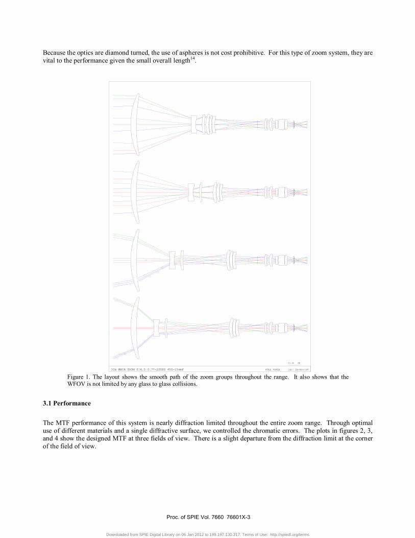
Because the optics are diamond turned, the use of aspheres is not cost prohibitive. For this type of zoom system, they arevital to the performance given the small overall length14.
30x MWIR ZOOM F/4.5 0.77-22DEG 455-15mmF FULL SCALE jdc 25-Nov-09
25.00 MM
Figure 1. The layout shows the smooth path of the zoom groups throughout the range. It also shows that theWFOV is not limited by any glass to glass collisions.
3.1 Performance
The MTF performance of this system is nearly diffraction limited throughout the entire zoom range. Through optimaluse of different materials and a single diffractive surface, we controlled the chromatic errors. The plots in figures 2, 3,and 4 show the designed MTF at three fields of view. There is a slight departure from the diffraction limit at the cornerof the field of view.
Proc. of SPIE Vol. 7660 76601X-3
Downloaded from SPIE Digital Library on 06 Jan 2012 to 199.197.130.217. Terms of Use: http://spiedl.org/terms

1.0
0.9
0.8
0.7
0.6
0.5
0.4
0.3
0.2
0.1
MODULATION
7.50 15.00 22.50 30.00SPATIAL FREQUENCY (CYCLES/MM)
R T
EFL 454mm
DIFFRACTION MTF
07-Jan-10POSITION 1
DIFFRACTION LIMIT T R 0.0 FIELD ( )0.00O
T R 0.3 FIELD ( )0.23O
T R 0.5 FIELD ( )0.39O
T R 0.6 FIELD ( )0.46O
T R 1.0 FIELD ( )0.77O
WAVELENGTH WEIGHT5000.0 NM 14500.0 NM 14000.0 NM 13500.0 NM 13000.0 NM 1
DEFOCUSING 0.00000
Figure 2. The NFOV MTF is shown out to Nyquist of the designed camera. It is close to the diffraction limit forthe entire field.
1.0
0.9
0.8
0.7
0.6
0.5
0.4
0.3
0.2
0.1
MODULATION
3.0 6.0 9.0 12.0 15.0 18.0 21.0 24.0 27.0 30.0SPATIAL FREQUENCY (CYCLES/MM)
R T
EFL 152mm
DIFFRACTION MTF
07-Jan-10POSITION 2
DIFFRACTION LIMIT T R 0.0 FIELD ( )0.00O
T R 0.3 FIELD ( )0.70O
T R 0.5 FIELD ( )1.16O
T R 0.6 FIELD ( )1.39O
T R 1.0 FIELD ( )2.32O
WAVELENGTH WEIGHT5000.0 NM 14500.0 NM 14000.0 NM 13500.0 NM 13000.0 NM 1
DEFOCUSING 0.00000
Figure 3. A typical MFOV MTF is shown out to Nyquist of the designed camera. Through most of the zoomrange, the system is diffraction limited.
Proc. of SPIE Vol. 7660 76601X-4
Downloaded from SPIE Digital Library on 06 Jan 2012 to 199.197.130.217. Terms of Use: http://spiedl.org/terms

1.0
0.9
0.8
0.7
0.6
0.5
0.4
0.3
0.2
0.1
MODULATION
3.0 6.0 9.0 12.0 15.0 18.0 21.0 24.0 27.0 30.0SPATIAL FREQUENCY (CYCLES/MM)
R T
EFL 15.24mm
DIFFRACTION MTF
07-Jan-10POSITION 3
DIFFRACTION LIMIT T R 0.0 FIELD ( )0.00O
T R 0.3 FIELD ( )6.59O
T R 0.5 FIELD ( )10.99O
T R 0.6 FIELD ( )13.19O
T R 1.0 FIELD ( )21.98O
WAVELENGTH WEIGHT5000.0 NM 14500.0 NM 14000.0 NM 13500.0 NM 13000.0 NM 1
DEFOCUSING 0.00000
Figure 4. The WFOV MTF is shown out to Nyquist of the designed camera. There is some drop in performanceonly at the very corner of the FOV.
Furthermore, the distortion of this zoom system is under 0.5% for the entire 30X range. Figure 5 shows the distortionacross the full focal length range.
Maximum Distortion vs EFL
0.00%
0.05%
0.10%
0.15%
0.20%
0.25%
0.30%
0.35%
0.40%
0.45%
0.50%
0 50 100 150 200 250 300 350 400 450 500
EFL
Perc
ent D
isto
rtio
n
Figure 5. The distortion of the system is low through the entire zoom range.
3.2 Zoom group motions
Shown in figure 6 is the continuous motion of the zoom groups. Extra precautions were taken around the case where themagnification of the zoom section equals 1X. The focal length of the system and the movement of the lens groups aresmooth and continuous. The number of zoom configurations selected during optimization was based upon evaluating thepreliminary design over very small focal length changes over the zoom range. The evaluation revealed several focallengths to include in the optimization, while keeping the number of configurations to a minimum for speedconsiderations.
Proc. of SPIE Vol. 7660 76601X-5
Downloaded from SPIE Digital Library on 06 Jan 2012 to 199.197.130.217. Terms of Use: http://spiedl.org/terms

Zoom Group Motions
0
2
4
6
8
10
12
-150 -100 -50 0 50
Distance from Zoom Object Plane
Zoom
Mag
nific
atio
n
First Zoom GroupLocation
Second Zoom GroupLocation
Figure 6. The zoom paths of the system are smooth. We used extra care in the region where the zoommagnification was 1X.
Figure 7 demonstrates the ability of the zoom groups to “switch roots” around the 1X. Figure 7 depicts the close look atthe zoom group motions near the 1X magnification. Two solutions allow the groups to have a given magnification.Although the focal length of the system is the same with these alternate positions, the performance of the lens quicklydeteriorates as you move away from the 1X zoom position. This deterioration results from the alternate positions notbeing used during the optimization.
Zoom Group Motions
0.5
0.6
0.7
0.8
0.9
1
1.1
1.2
1.3
1.4
1.5
-120 -100 -80 -60 -40 -20 0 20 40 60
Axial Position
Zoom
Gro
up M
agni
ficat
ion
First Zoom Group Position
Second Zoom GroupPositionFirst Zoom Group -Alternate PathSecond Zoom Group -Alternate Path
Figure 7. The “alternative” zoom paths deviate from the smooth designed path at the 1X zoom magnificationlocation.
Proc. of SPIE Vol. 7660 76601X-6
Downloaded from SPIE Digital Library on 06 Jan 2012 to 199.197.130.217. Terms of Use: http://spiedl.org/terms
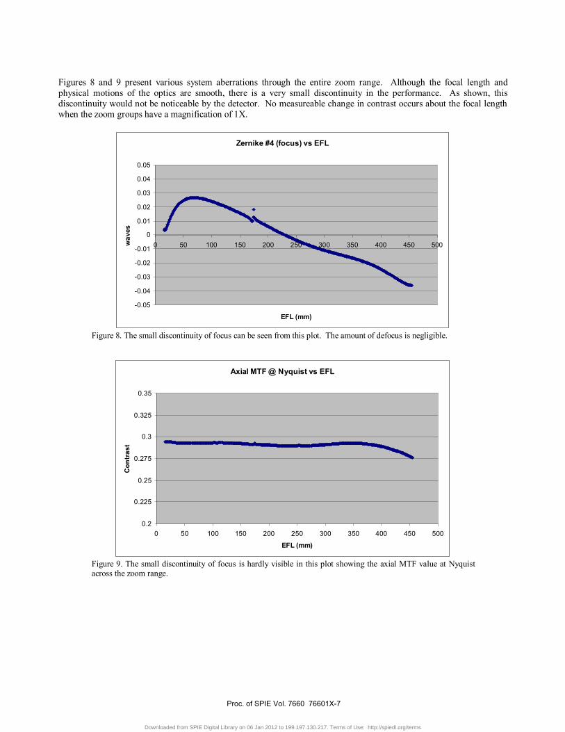
Figures 8 and 9 present various system aberrations through the entire zoom range. Although the focal length andphysical motions of the optics are smooth, there is a very small discontinuity in the performance. As shown, thisdiscontinuity would not be noticeable by the detector. No measureable change in contrast occurs about the focal lengthwhen the zoom groups have a magnification of 1X.
Zernike #4 (focus) vs EFL
-0.05
-0.04
-0.03
-0.02
-0.01
0
0.01
0.02
0.03
0.04
0.05
0 50 100 150 200 250 300 350 400 450 500
EFL (mm)
wav
es
Figure 8. The small discontinuity of focus can be seen from this plot. The amount of defocus is negligible.
Axial MTF @ Nyquist vs EFL
0.2
0.225
0.25
0.275
0.3
0.325
0.35
0 50 100 150 200 250 300 350 400 450 500
EFL (mm)
Con
tras
t
Figure 9. The small discontinuity of focus is hardly visible in this plot showing the axial MTF value at Nyquistacross the zoom range.
Proc. of SPIE Vol. 7660 76601X-7
Downloaded from SPIE Digital Library on 06 Jan 2012 to 199.197.130.217. Terms of Use: http://spiedl.org/terms

3.3 Sensitivities
The angles of incidence were controlled during the design to prevent problems for coating as well as to help controlsensitivities. The most sensitive airspaces were found in the 2nd zoom group at the NFOV and the final air-spaceddoublet of the relay. These airspaces will be controlled very precisely during the build process.
By keeping the powers of the zoom groups as large as possible we were able to keep the sensitivity of the groups lowfrom the beginning. We discovered the zoom groups could handle a +/-50μm decentration tolerance and still have noimpact to MTF or distortion. Boresight was the parameter that was most effected, but it can be compensated.
3.4 Narcissus
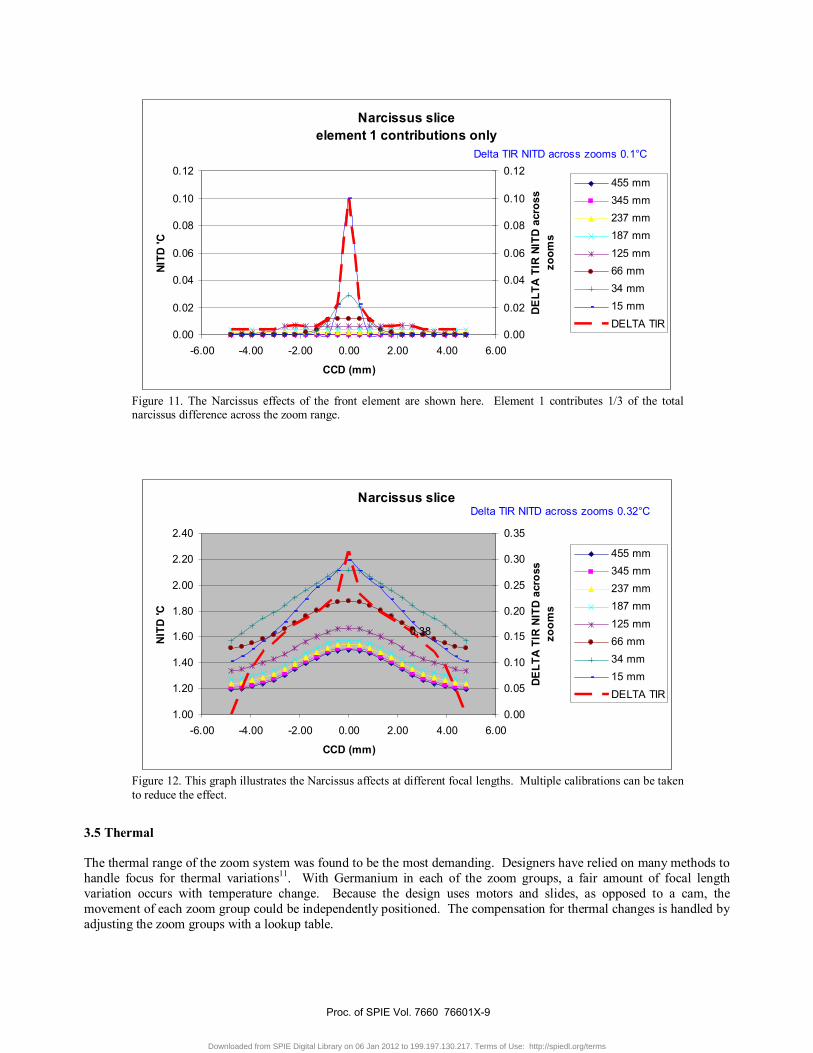
This system is configured for cameras that contain staring arrays and cold stops. Since the elements are moving theeffects of narcissus change must be examined5,15. The first order narcissus contributing quantities of YNI and I/Ib as wellas single bounce ghost reflections from the cold stop back to the FPA were evaluated and selected surfaces were targetedduring optimization. The zoom range will require the camera to be capable of calibrating the effects of the narcissus forseveral regions through the zoom range. As mentioned prior, the decision was made to keep the front objective group asa single element. Using LightTools16 non sequential ray tracing and ray path filtering, the main contributors to narcissuscan be identified. Figures 10 and 11 show the primary surfaces on the objective element that contribute to narcissus atthe WFOV. Figure 12 reviews the results of the initial narcissus analysis for all surfaces. To reduce the effect of thefront surfaces, the coatings will be geared toward minimizing the low angle of incidence reflections in the regions used atthe WFOV.
Figure 10. The front element is the largest contributor to narcissus. The single bounce ghost is shown here.
Proc. of SPIE Vol. 7660 76601X-8
Downloaded from SPIE Digital Library on 06 Jan 2012 to 199.197.130.217. Terms of Use: http://spiedl.org/terms
Narcissus sliceelement 1 contributions only
0.00
0.02
0.04
0.06
0.08
0.10
0.12
-6.00 -4.00 -2.00 0.00 2.00 4.00 6.00
CCD (mm)
NITD
'C
0.00
0.02
0.04
0.06
0.08
0.10
0.12
DE
LTA
TIR
NIT
D a
cros
szo
oms
455 mm345 mm237 mm187 mm125 mm66 mm34 mm15 mmDELTA TIR
Delta TIR NITD across zooms 0.1°C
Figure 11. The Narcissus effects of the front element are shown here. Element 1 contributes 1/3 of the totalnarcissus difference across the zoom range.
Narcissus slice
1.00
1.20
1.40
1.60
1.80
2.00
2.20
2.40
-6.00 -4.00 -2.00 0.00 2.00 4.00 6.00
CCD (mm)
NIT
D 'C
0.00
0.05
0.10
0.15
0.20
0.25
0.30
0.35DE
LTA
TIR
NIT
D a
cros
szo
oms
455 mm345 mm237 mm187 mm125 mm66 mm34 mm15 mmDELTA TIR
0.38
Delta TIR NITD across zooms 0.32°C
Figure 12. This graph illustrates the Narcissus affects at different focal lengths. Multiple calibrations can be takento reduce the effect.
3.5 Thermal
The thermal range of the zoom system was found to be the most demanding. Designers have relied on many methods tohandle focus for thermal variations11. With Germanium in each of the zoom groups, a fair amount of focal lengthvariation occurs with temperature change. Because the design uses motors and slides, as opposed to a cam, themovement of each zoom group could be independently positioned. The compensation for thermal changes is handled byadjusting the zoom groups with a lookup table.
Proc. of SPIE Vol. 7660 76601X-9
Downloaded from SPIE Digital Library on 06 Jan 2012 to 199.197.130.217. Terms of Use: http://spiedl.org/terms

The image performance was fully recoverable through compensation across a very broad thermal range. Figure 13depicts the NFOV and WFOV at temperature extremes of -40°C and +60°C.
1.0
0.9
0.8
0.7
0.6
0.5
0.4
0.3
0.2
0.1
MODULATION
7.50 15.00 22.50 30.00SPATIAL FREQUENCY (CYCLES/MM)
R T
NFOV -40C
DIFFRACTION MTF
15-Jan-10
DIFFRACTION LIMIT T R 0.0 FIELD ( )0.00O
T R 0.3 FIELD ( )0.23O
T R 0.5 FIELD ( )0.39O
T R 0.6 FIELD ( )0.46O
T R 1.0 FIELD ( )0.77O
WAVELENGTH WEIGHT5000.0 NM 14500.0 NM 14000.0 NM 13500.0 NM 13000.0 NM 1
DEFOCUSING 0.000001.0
0.9
0.8
0.7
0.6
0.5
0.4
0.3
0.2
0.1
MODULATION
7.50 15.00 22.50 30.00SPATIAL FREQUENCY (CYCLES/MM)
R T
NFOV +60C
DIFFRACTION MTF
15-Jan-10
DIFFRACTION LIMIT T R 0.0 FIELD ( )0.00O
T R 0.3 FIELD ( )0.23O
T R 0.5 FIELD ( )0.39O
T R 0.6 FIELD ( )0.46O
T R 1.0 FIELD ( )0.77O
WAVELENGTH WEIGHT5000.0 NM 14500.0 NM 14000.0 NM 13500.0 NM 13000.0 NM 1
DEFOCUSING 0.00000
1.0
0.9
0.8
0.7
0.6
0.5
0.4
0.3
0.2
0.1
MODULATION
7.50 15.00 22.50 30.00SPATIAL FREQUENCY (CYCLES/MM)
R T
WFOV -40C
DIFFRACTION MTF
15-Jan-10
DIFFRACTION LIMIT T R 0.0 FIELD ( )0.00O
T R 0.3 FIELD ( )6.59O
T R 0.5 FIELD ( )10.99O
T R 0.6 FIELD ( )13.19O
T R 1.0 FIELD ( )21.98O
WAVELENGTH WEIGHT5000.0 NM 14500.0 NM 14000.0 NM 13500.0 NM 13000.0 NM 1
DEFOCUSING 0.000001.0
0.9
0.8
0.7
0.6
0.5
0.4
0.3
0.2
0.1
MODULATION
7.50 15.00 22.50 30.00SPATIAL FREQUENCY (CYCLES/MM)
R T
WFOV +60C
DIFFRACTION MTF
15-Jan-10
DIFFRACTION LIMIT T R 0.0 FIELD ( )0.00O
T R 0.3 FIELD ( )6.59O
T R 0.5 FIELD ( )10.99O
T R 0.6 FIELD ( )13.19O
T R 1.0 FIELD ( )21.98O
WAVELENGTH WEIGHT5000.0 NM 14500.0 NM 14000.0 NM 13500.0 NM 13000.0 NM 1
DEFOCUSING 0.00000
Figure 13. The MTF plots of the NFOV and WFOV at both temperature extremes show no loss of performanceafter application of active compensation.
3.7 Image Simulations
In figure 14 & 15 the results of CODE V17 image simulation are displayed18. The nearly diffraction limited performanceat both ends of the 30X zoom range are shown. The distortion at either focal length is not noticeable.
Figure 14. The object file is shown on the left and the results of the IMS are on the right. The performance is fromthe WFOV of the zoom system. The pixel size of the camera has been convolved with the performance of thelens.
Proc. of SPIE Vol. 7660 76601X-10
Downloaded from SPIE Digital Library on 06 Jan 2012 to 199.197.130.217. Terms of Use: http://spiedl.org/terms
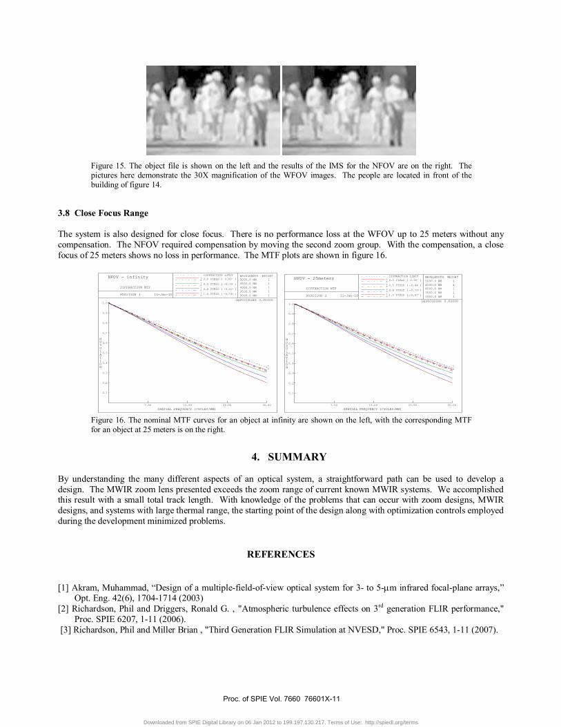
Figure 15. The object file is shown on the left and the results of the IMS for the NFOV are on the right. Thepictures here demonstrate the 30X magnification of the WFOV images. The people are located in front of thebuilding of figure 14.
3.8 Close Focus Range
The system is also designed for close focus. There is no performance loss at the WFOV up to 25 meters without anycompensation. The NFOV required compensation by moving the second zoom group. With the compensation, a closefocus of 25 meters shows no loss in performance. The MTF plots are shown in figure 16.
1.0
0.9
0.8
0.7
0.6
0.5
0.4
0.3
0.2
0.1
MODULATION
7.50 15.00 22.50 30.00SPATIAL FREQUENCY (CYCLES/MM)
R T
NFOV - infinity
DIFFRACTION MTF
11-Jan-10POSITION 1
DIFFRACTION LIMIT T R 0.0 FIELD ( )0.00O
T R 0.5 FIELD ( )-0.39O
T R 0.8 FIELD ( )-0.62O
T R 1.0 FIELD ( )-0.78O
WAVELENGTH WEIGHT5000.0 NM 14500.0 NM 14000.0 NM 13500.0 NM 13000.0 NM 1
DEFOCUSING 0.000001.0
0.9
0.8
0.7
0.6
0.5
0.4
0.3
0.2
0.1
MODULATION
7.50 15.00 22.50 30.00SPATIAL FREQUENCY (CYCLES/MM)
R T
NFOV - 25meters
DIFFRACTION MTF
11-Jan-10POSITION 2
DIFFRACTION LIMIT T R 0.0 FIELD ( )0.00O
T R 0.5 FIELD ( )-0.44O
T R 0.8 FIELD ( )-0.70O
T R 1.0 FIELD ( )-0.87O
WAVELENGTH WEIGHT5000.0 NM 14500.0 NM 14000.0 NM 13500.0 NM 13000.0 NM 1
DEFOCUSING 0.00000
Figure 16. The nominal MTF curves for an object at infinity are shown on the left, with the corresponding MTFfor an object at 25 meters is on the right.
4. SUMMARY
By understanding the many different aspects of an optical system, a straightforward path can be used to develop adesign. The MWIR zoom lens presented exceeds the zoom range of current known MWIR systems. We accomplishedthis result with a small total track length. With knowledge of the problems that can occur with zoom designs, MWIRdesigns, and systems with large thermal range, the starting point of the design along with optimization controls employedduring the development minimized problems.
REFERENCES
[1] Akram, Muhammad, “Design of a multiple-field-of-view optical system for 3- to 5-μm infrared focal-plane arrays,”Opt. Eng. 42(6), 1704-1714 (2003)
[2] Richardson, Phil and Driggers, Ronald G. , "Atmospheric turbulence effects on 3rd generation FLIR performance,"Proc. SPIE 6207, 1-11 (2006).
[3] Richardson, Phil and Miller Brian , "Third Generation FLIR Simulation at NVESD," Proc. SPIE 6543, 1-11 (2007).
Proc. of SPIE Vol. 7660 76601X-11
Downloaded from SPIE Digital Library on 06 Jan 2012 to 199.197.130.217. Terms of Use: http://spiedl.org/terms

[4] Vizgaitis, Jay, “ Selecting Infrared Optical,” University of Arizona, Optics 52, December 14, 2006.[5] Scherr, Lawrence M., Orlando, Harold J., Hall, James T., and Godfrey, Thomas B. “Narcissus Considerations in
Optical Designs for Infrared Staring Arrays,” Proc. SPIE 2864, 442-451 (1996).[6] Feng-Yun, He, Ji-Cheng, Cui, Shu-Long, Feng, and Xin, Zhang, “Narcissus Analysis For Cooled Staring IR System,”
China Proc. of SPIE Vol. 6722, 1-7 (2007).[7] Yong, Li, Changcheng, Yang, and Shenghui, Li, “Design of Infrared Zoom System with Rotating Lens Group”, Proc.
of SPIE Vol. 6834, 68343Y (2007).[8] Akram, Muhammad, “Design of a Dual Field-of-View Optical System for Infra-Red, Focal-Plane Arrays”, Proc.
SPIE Vol. 4767, 13-23 (2002).[9] Patent US4486069(A)[10] Neil, Iain A., “Optimization glitches in zoom lens design,” SPIE Vol. 3129, pg 158-180 (1997).[11] Ford, Eric, “Active Temperature Compensation of an Infrared Zoom Lens,” SPIEVoI. 3129, 138-143 (1997).[12] Fischer, Robert and U.Kampe Thomas, “Actively Controlled 5:1 Afocal Zoom Attachment, for Common Module
FLIR,” SPIE Vol. 1690, 137-152 (1992).[13] ChunKan, Tao, “Design of zoom system by the varifocal differential equation,” Applied Optics VoI. 31, 2265-2273(1992).[14] Betensky, Ellis, “The role of aspherics in zoom lens design”, SPIE Vol. 1354, 656-662 (1990).[15] Feng-Yun, He, Ji-Cheng, Cui, Shu-Long, Feng, and Xin, Zhang, “Narcissus Analysis For Cooled Staring IRSystem,” Proc. of SPIE Vol. 6722, 1-7 (2007).[16] CODE V is a registered trademark of Optical Research Associates[17] LightTools is a registered trademark of Optical Research Associates[18] Image used with permission from Talke Photography
Proc. of SPIE Vol. 7660 76601X-12
Downloaded from SPIE Digital Library on 06 Jan 2012 to 199.197.130.217. Terms of Use: http://spiedl.org/terms