mxs-e 4-way blow ceiling mounted cassette multi split heat...
TRANSCRIPT
FCQ-D
4-way Blow CeilingMounted Cassette(950mm x 950mm)
technical data
SplitSky Air
air conditioning systems
MXS-E
Multi Split Heat Pump(edited)

• Outdoor Units • R410A • MXS-DAVMB_E2V1B_E7V3B
11
• Split Sky Air • Outdoor Units1
1 Features
Outdoor Uni Split Sky A MXS-DAVMB_E2V R410a • Outdoor units for Multi model application.
• Up to 5 indoor units can be connected to 1 Multi outdoor unit. All indoor units are individually controllable with remote control and do not need to be installed in the same room or at the same time. They operate simultaneously within the same cooling operation
• It is possible to combine dif ferent types of indoor units as well. (e.g. wall mounted, ceiling mounted cassette corner, concealed ceiling unit)
• Daikin outdoor units are neat and sturdy and can be mounted easily on a roof or terrace or simply placed against an outside wall.
• Outdoor units are fitted with a swing compressor, renowned for its low noise and high energy eff iciency

3
12
• Split Sky Air • Outdoor Units 2
• Outdoor Units • R410A • MXS-DAVMB_E2V1B_E7V3B
2 Specifications
2-1 TECHNICAL SPECIFICATIONS 2MXS4 0DAVMB 2MXS52E2V1B 3MXS52E2V1B 4MXS68E2V1B 4MXS80E7V3B 5MXS90E7V3B
Casing Colour Ivory WhiteDimensions Unit Height mm 640 735 735 735 770 770
Width mm 685 936 936 936 900 900Depth mm 285 300 300 300 320 320
Packing Height mm 676 797 797 784 900 900Width mm 800 992 992 992 925 925Depth mm 366 390 390 390 390 390
Weight Unit kg 39 49 49 59 72 73Packed Unit kg 42 56 56 65 80 80
Heat Exchanger
Dimensions Length mm 678 845 845 845 860 860Nr of Rows 1 2 2 2 2 2Fin Pitch mm 1.4 1.80 1.80 1.60 1.40 1.40Nr of Stages 28 32 32 32 34 34
Tube type Hi-Xa(8) ø7.94 grooved tubes 24
ø7.94 grooved tubes 24
Hi-Xa(8) Hi-XSS(8) Hi-XSS(8)
Fin Type WF fin Colgate fin Colgate fin WF fin WF fin WF finTreatment Anti- corrosion
treatment (PE)Anti- corrosion treatment (PE)
Anti- cor ros ion treatment (PE)
Anti-cor ros ion treatment (PE)
Fan Type PropellerQuantity 1 1 1 1 1 1Air Flow Rate (nominal at 230V)
Cooling m³/min 35 45.0 45.0 51.0 54.5 54.5Heating m³/min 32 45.0 45.0 47.6 46.0
Motor Quantity 1 1 1 1 1 1Model D50E-28 KFD-380-50-8A KFD-380-50-8A KFD-380-53-8C KFD-280-66-8A KFD-280-66-8A
Motor Speed (nominal)
Cooling rpm 880 720 720 790 860Heating rpm 880 720 790
Fan Motor Output W 50 53 53 53 66 66Compressor Quantity 1 1 1 1 1
Motor Model 1YC23GXD 2YC36BXD 2YC36BXD 2YC45BXD 2YC63BXD#C 2YC63BXD#CType Hermetically sealed swing compressorMotor Output
W 600 1100 1100 1380 1920 1920
Operation Range
Cooling Min °CDB 10 -10.0 -10.0 -10.0 -10.0 -10.0Max °CDB 46 46.0 46.0 46.0 46.0 46.0
Heating Min °CWB -10 -15 -15 -15 -15 -15Max °CWB 15.5 15.5 15.5 15.5 15.5 15.5
Sound Level (nominal)
Cooling Sound Power
dBA 62 59.0 59.0 61.0 62.0 66.0
Sound Pressure
dBA 47 46.0 46.0 48.0 48.0 52.0
Heating Sound Pressure
dBA 48 47.0 47.0 49.0 49.0 52.0
Sound Level (Night quiet)
Sound Pressure dBA 43
Refrigerant Type R-410ACharge kg 1.20 2.0 2.0 2.6 3.0 3.0
Refrigerant Oil Type FVC50KCharged Volume l 0.40 0.65 0.65 0.75 0.75 0.75

• Outdoor Units • R410A • MXS-DAVMB_E2V1B_E7V3B
12
• Split Sky Air • Outdoor Units3
2 Specifications
Piping connections
Liquid (OD) Quantity 2 2 3 4 4 5Diameter (OD)
mm 6.35 6.35 6.35 6.35 6.35 6.35
Gas Quantity 2 2 2 2 1 2Diameter (OD)
mm 9.5 12.7 9.5 9.5 9.5 9.5
Quantity 1 2 1 1Diameter (OD)
mm 12.7 12.7 12.7 12.7
Quantity 2 2Diameter (OD)
mm 15.9 15.9
Drain Quantity 1Diameter (OD)
mm 18 18 18 18 25 25
Piping Length Minimum m 1.5 (for one room)Maximum m 30 ( for total of
each room) , 20 (for one room)
50 ( for total of each room) /25 (for one room)
50 (for total of each room) / 25 (for one room)
60 (for total of each room)/ 25 (for one room)
70 (for total of each room)/ 25 (for one room)
75 (for total of each room)/ 25 ( for one room)
Additional Refrigerant Charge
kg/m 0.02/>20 0.02/>30m 0.02/>30m 0.02/>30m 0.02/>30m 0.02/>30m
Installation height difference
Maximum m 15(between indoor unit and outdoor unit)
15.0 (between indoor unit and outdoor unit)
15.0 (between indoor unit and outdoor unit)
15.0 (between indoor unit and outdoor unit)
15.0 (between indoor unit and outdoor unit)
15.0 (between indoor unit and outdoor unit)
Max. internunit level difference
m 7.5 (between indoor units)
7.5 (between indoor units)
7.5 (between indoor units)
7.5 (between indoor units)
7.5 (between indoor units)
7.5 (between indoor units)
Heat Insulation Both liquid and gas pipesStandard Accessories
Item Installation manualQuantity 1 pc 1 1 1 1 1Item Screw bag Drain plug Drain plug Drain plug Drain plug Drain plugQuantity 1 pc 1 1 1 1 1Item Reducer
assemblyReducer assembly
Reducer assembly
Reducer assembly
Reducer assembly
Quantity 1 1 1 1 1Notes Nominal cooling capacities are based on : indoor temperature : 270CDB, 190CWB, outdoor temperature : 350CDB,
equivalent refrigerant piping : 7.5m, level difference : 0m.Nominal heating capacities are based on : indoor temperature : 200CDB, outdoor temperature : 70CDB, 60CWB,
equivalent refrigerant piping : 7.5m, level difference : 0mSound levels are measured in an anechoic room
Sound pressure level is a relative value, depending on the distance and acoustic env ironment. For more details, please refer to sound level drawings of this chapter.
The sound power level is an absolute value indicating the power which a sound source generates.
2-2 ELECTRICAL SPECIFICATIONS 2MXS40DAVMB 2 MXS52E2V1B 3 MXS52E2V1B 4MXS68E2V1B 4MXS80E7V3B 5MXS90E7V3B
Power Supply Name VM V1 V1 V1 V3 V3Phase 1 1 1 1 1 1Frequency Hz 50/60 50 50 50 50 50Voltage V 220-240/220-230 230 230 230 230 230Voltage range Minimum V -10% -10% -10% -10% -10%
Maximum V +10% +10% +10% +10% +10%Current Nominal
running cur rent (RLA)
Cooling (A)
A 0.33 0.33 0.33 0.97 0.97
Heating (A)
A 0.33 0.33 0.33 0.69
Starting current (cooling/heating)
A 6.2 6.7 6.2 8.5 9.7 11.8
Z-max Lis t No requirements
2-1 TECHNICAL SPECIFICATIONS 2MXS40DAVMB 2 MXS52E2V1B 3 MXS52E2V1B 4MXS68E2V1B 4MXS80E7V3B 5MXS90E7V3B
3
12
• Split Sky Air • Outdoor Units 4
• Outdoor Units • R410A • MXS-DAVMB_E2V1B_E7V3B
2 Specifications
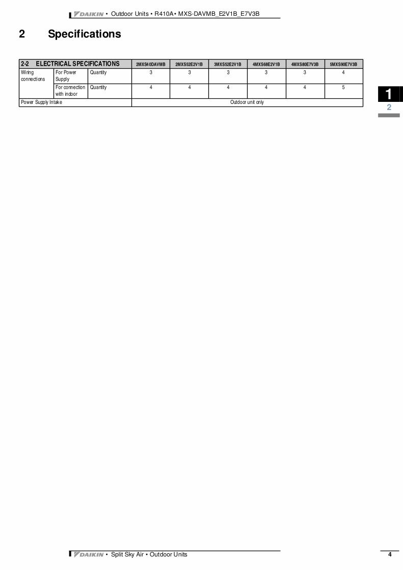
Wiring connections
For Power Supply
Quantity 3 3 3 3 3 4
For connection with indoor
Quantity 4 4 4 4 4 5
Power Supply Intake Outdoor unit only
2-2 ELECTRICAL SPECIFICATIONS 2MXS4 0DAVMB 2MXS52E2V1B 3MXS52E2V1B 4MXS68E2V1B 4MXS80E7V3B 5MXS90E7V3B

• Outdoor Units • R410A • MXS-DAVMB_E2V1B_E7V3B
13
• Split Sky Air • Outdoor Units5
3 Electrical data
Cooling (50Hz 230V)
Combination Units Power supply Comp. OFM IFMHz Volts Min. Max. MCA MFA RLA W FLA W FLA
2.0
50 230 207 253
3.4
12
2.3
50 0.40
40 0.172.5 4.7 3.0 40 0.173.5 6.5 4.6 40 0.172.0+2.0 6.7 4.9 80 0.342.0+2.5 6.7 5.0 80 0.342.0+3.5 6.8 5.0 80 0.342.5+2.5 6.8 5.0 80 0.342.5+3.5 6.8 5.0 80 0.34
Heating (50Hz 230V)
Combination Units Power supply Comp. OFM IFMHz Volts Min. Max. MCA MFA RLA W FLA W FLA
2.0
50 230 207 253
6.2
12
4.1
50 0.40
40 0.172.5 7.5 4.7 40 0.173.5 8.6 5.7 40 0.172.0+2.0 6.4 4.6 80 0.342.0+2.5 6.6 4.8 80 0.342.0+3.5 6.6 4.8 80 0.342.5+2.5 6.6 4.8 80 0.342.5+3.5 6.6 4.8 80 0.34
SYMBOLSMCA : Min. Circuit Amps (A)MFA : Max. Fuse Amps (A)RLA : Rated Load Amps (A)OFM : Outdoor Fan MotorIFM : Indoor Fan MotorFLA : Full Load Amps (A)W : Fan Motor Rated Output (W)
NOTES1. RLA is based on the following conditions:
Power supply: 50Hz 240VCoolingIndoor temp.: 27°CDB/19.0°CWBOutdoor temp. : 35°CDBHeatingIndoor temp.: 20°CDBOutdoor temp.: 7°CDB/6°CWB
2. Maximum allowable voltage unbalance between phases is 2%3. Select wire size based on the larger value of MCA.4. Instead of fuse, use circuit breaker5. For more details concerning conditional connections, see
http://eu.extranet.daikineurope.com, select ’’E-Data Books’’. Finally, click on thedocument title of your choice.

3
13
• Split Sky Air • Outdoor Units 6
• Outdoor Units • R410A • MXS-DAVMB_E2V1B_E7V3B
3 Electrical data
3D052807
SYMBOLSMCA : Min. Circuit Amps (A)MFA : Max. Fuse Amps (See note 6). (A)MSC : MSC means the max. current during the starting of
compressor. (A)RLA : Rated Load Amps (A)OFM : Outdoor Fan MotorIFM : Indoor Fan MotorFLA : Full Load Amps (A)W : Fan Motor Rated Output (W)
NOTES1. RLA is based on the following conditions:
CoolingIndoor temp.: 27°CDB/19.0°CWBOutdoor temp. : 35°CDB
2. Voltage rangeUnits are suitable for use on electrical systems where voltage supplied to unit terminals isnot below or above listed operation range limits
3. Maximum allowable voltage variation between phases is 2%4. MCA represents maximum input current.
MFA represents capacity which may accept MCA5. Select wire size based on the larger value of MCA.6. MFA is used to select the circuit breaker and the ground fault circuit interrupter
(earth leakage circuit breaker)7. For more details concerning conditional connections, see
http://extranet.daikineurope.com, select ’’E-Data Books’’. Finally, click on the document titleof your choice.
3MXS52E
Model Units Power supply Comp. OFM
Outdoor H/PC/D Hz Volts Min. Max. MCA MFA MSC RLA W FLA

• Outdoor Units • R410A • MXS-DAVMB_E2V1B_E7V3B
13
• Split Sky Air • Outdoor Units7
3 Electrical data
SYMBOLSMCA : Min. Circuit Amps (A)MFA : Max. Fuse Amps (A)RLA : Rated Load Amps (A)OFM : Outdoor Fan MotorIFM : Indoor Fan MotorFLA : Full Load Amps (A)W : Fan Motor Rated Output (W)
NOTES1. RLA is based on the following conditions:
Power supply: 50Hz 230VCoolingIndoor temp.: 27°CDB/19.5°CWBOutdoor temp. : 35°CDBHeatingIndoor temp.: 20°CDBOutdoor temp.: 7°CDB/6°CWB
2. Maximum allowable voltage unbalance between phases is 2%3. Select wire size based on the larger value of MCA.4. Instead of fuse, use circuit breaker5. The above is the value for connecting with the following indoor units.
2.0, 2.5, 3.5kW class: wall mounted C series5.0, 6.0kW class: wall mounted B series
6. Be sure to install an earth leak detector. (One that can handle higher harmonics.)(This unit uses an inverter, which means that it must be used an earth leak detectorcapable handling high harmonics in order to prevent malfunctioning of the earth leakdetector.)
7. For more details concerning conditional connections, seehttp://extranet.daikineurope.com, select ’’E-Data Books’’. Finally, click on the documenttitle of your choice.
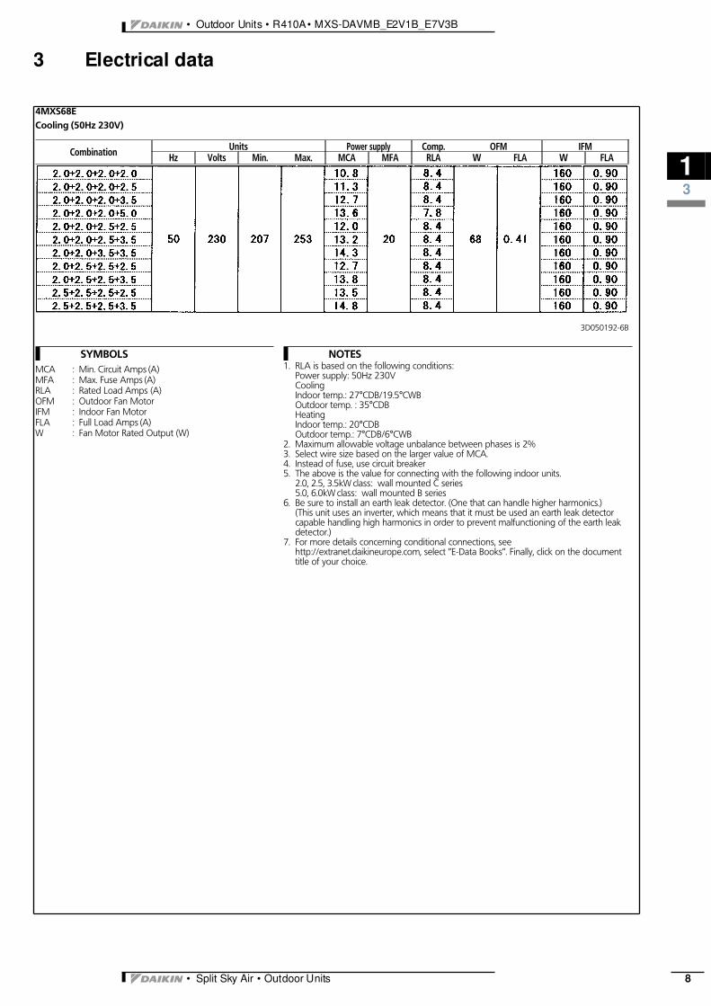
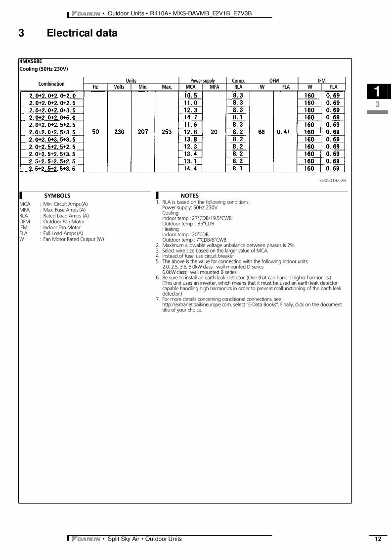
4MXS68ECooling (50Hz 230V)
Combination Units Power supply Comp. OFM IFMHz Volts Min. Max. MCA MFA RLA W FLA W FLA
3D050192-5B
3
13
• Split Sky Air • Outdoor Units 8
• Outdoor Units • R410A • MXS-DAVMB_E2V1B_E7V3B
3 Electrical data
SYMBOLSMCA : Min. Circuit Amps (A)MFA : Max. Fuse Amps (A)RLA : Rated Load Amps (A)OFM : Outdoor Fan MotorIFM : Indoor Fan MotorFLA : Full Load Amps (A)W : Fan Motor Rated Output (W)
NOTES1. RLA is based on the following conditions:
Power supply: 50Hz 230VCoolingIndoor temp.: 27°CDB/19.5°CWBOutdoor temp. : 35°CDBHeatingIndoor temp.: 20°CDBOutdoor temp.: 7°CDB/6°CWB
2. Maximum allowable voltage unbalance between phases is 2%3. Select wire size based on the larger value of MCA.4. Instead of fuse, use circuit breaker5. The above is the value for connecting with the following indoor units.
2.0, 2.5, 3.5kW class: wall mounted C series5.0, 6.0kW class: wall mounted B series
6. Be sure to install an earth leak detector. (One that can handle higher harmonics.)(This unit uses an inverter, which means that it must be used an earth leak detectorcapable handling high harmonics in order to prevent malfunctioning of the earth leakdetector.)
7. For more details concerning conditional connections, seehttp://extranet.daikineurope.com, select ’’E-Data Books’’. Finally, click on the documenttitle of your choice.
4MXS68ECooling (50Hz 230V)
Combination Units Power supply Comp. OFM IFMHz Volts Min. Max. MCA MFA RLA W FLA W FLA
3D050192-6B
• Outdoor Units • R410A • MXS-DAVMB_E2V1B_E7V3B
13
• Split Sky Air • Outdoor Units9
3 Electrical data
SYMBOLSMCA : Min. Circuit Amps (A)MFA : Max. Fuse Amps (A)RLA : Rated Load Amps (A)OFM : Outdoor Fan MotorIFM : Indoor Fan MotorFLA : Full Load Amps (A)W : Fan Motor Rated Output (W)
NOTES1. RLA is based on the following conditions:
Power supply: 50Hz 230VCoolingIndoor temp.: 27°CDB/19.5°CWBOutdoor temp. : 35°CDBHeatingIndoor temp.: 20°CDBOutdoor temp.: 7°CDB/6°CWB
2. Maximum allowable voltage unbalance between phases is 2%3. Select wire size based on the larger value of MCA.4. Instead of fuse, use circuit breaker5. The above is the value for connecting with the following indoor units.
2.0, 2.5, 3.5kW class: wall mounted C series5.0, 6.0kW class: wall mounted B series
6. Be sure to install an earth leak detector. (One that can handle higher harmonics.)(This unit uses an inverter, which means that it must be used an earth leak detectorcapable handling high harmonics in order to prevent malfunctioning of the earth leakdetector.)
7. For more details concerning conditional connections, seehttp://extranet.daikineurope.com, select ’’E-Data Books’’. Finally, click on the documenttitle of your choice.
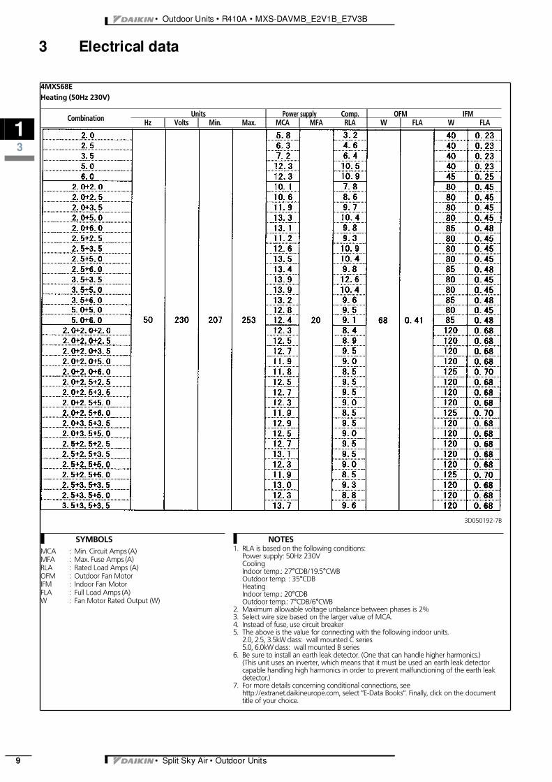
4MXS68EHeating (50Hz 230V)
Combination Units Power supply Comp. OFM IFMHz Volts Min. Max. MCA MFA RLA W FLA W FLA
3D050192-7B

3
13
• Split Sky Air • Outdoor Units 10
• Outdoor Units • R410A • MXS-DAVMB_E2V1B_E7V3B
3 Electrical data
SYMBOLSMCA : Min. Circuit Amps (A)MFA : Max. Fuse Amps (A)RLA : Rated Load Amps (A)OFM : Outdoor Fan MotorIFM : Indoor Fan MotorFLA : Full Load Amps (A)W : Fan Motor Rated Output (W)
NOTES1. RLA is based on the following conditions:
Power supply: 50Hz 230VCoolingIndoor temp.: 27°CDB/19.5°CWBOutdoor temp. : 35°CDBHeatingIndoor temp.: 20°CDBOutdoor temp.: 7°CDB/6°CWB
2. Maximum allowable voltage unbalance between phases is 2%3. Select wire size based on the larger value of MCA.4. Instead of fuse, use circuit breaker5. The above is the value for connecting with the following indoor units.
2.0, 2.5, 3.5kW class: wall mounted C series5.0, 6.0kW class: wall mounted B series
6. Be sure to install an earth leak detector. (One that can handle higher harmonics.)(This unit uses an inverter, which means that it must be used an earth leak detectorcapable handling high harmonics in order to prevent malfunctioning of the earth leakdetector.)
7. For more details concerning conditional connections, seehttp://extranet.daikineurope.com, select ’’E-Data Books’’. Finally, click on the documenttitle of your choice.
4MXS68EHeating (50Hz 230V)
Combination Units Power supply Comp. OFM IFMHz Volts Min. Max. MCA MFA RLA W FLA W FLA
3D050192-8B

• Outdoor Units • R410A • MXS-DAVMB_E2V1B_E7V3B
13
• Split Sky Air • Outdoor Units11
3 Electrical data
SYMBOLSMCA : Min. Circuit Amps (A)MFA : Max. Fuse Amps (A)RLA : Rated Load Amps (A)OFM : Outdoor Fan MotorIFM : Indoor Fan MotorFLA : Full Load Amps (A)W : Fan Motor Rated Output (W)
NOTES1. RLA is based on the following conditions:
Power supply: 50Hz 230VCoolingIndoor temp.: 27°CDB/19.5°CWBOutdoor temp. : 35°CDBHeatingIndoor temp.: 20°CDBOutdoor temp.: 7°CDB/6°CWB
2. Maximum allowable voltage unbalance between phases is 2%3. Select wire size based on the larger value of MCA.4. Instead of fuse, use circuit breaker5. The above is the value for connecting with the following indoor units.
2.0, 2.5, 3.5, 5.0kW class: wall mounted D series6.0kW class: wall mounted B series
6. Be sure to install an earth leak detector. (One that can handle higher harmonics.)(This unit uses an inverter, which means that it must be used an earth leak detectorcapable handling high harmonics in order to prevent malfunctioning of the earth leakdetector.)
7. For more details concerning conditional connections, seehttp://extranet.daikineurope.com, select ’’E-Data Books’’. Finally, click on the documenttitle of your choice.
4MXS68ECooling (50Hz 230V)
Combination Units Power supply Comp. OFM IFMHz Volts Min. Max. MCA MFA RLA W FLA W FLA
3D050192-1B
3
13
• Split Sky Air • Outdoor Units 12
• Outdoor Units • R410A • MXS-DAVMB_E2V1B_E7V3B
3 Electrical data
SYMBOLSMCA : Min. Circuit Amps (A)MFA : Max. Fuse Amps (A)RLA : Rated Load Amps (A)OFM : Outdoor Fan MotorIFM : Indoor Fan MotorFLA : Full Load Amps (A)W : Fan Motor Rated Output (W)
NOTES1. RLA is based on the following conditions:
Power supply: 50Hz 230VCoolingIndoor temp.: 27°CDB/19.5°CWBOutdoor temp. : 35°CDBHeatingIndoor temp.: 20°CDBOutdoor temp.: 7°CDB/6°CWB
2. Maximum allowable voltage unbalance between phases is 2%3. Select wire size based on the larger value of MCA.4. Instead of fuse, use circuit breaker5. The above is the value for connecting with the following indoor units.
2.0, 2.5, 3.5, 5.0kW class: wall mounted D series6.0kW class: wall mounted B series
6. Be sure to install an earth leak detector. (One that can handle higher harmonics.)(This unit uses an inverter, which means that it must be used an earth leak detectorcapable handling high harmonics in order to prevent malfunctioning of the earth leakdetector.)
7. For more details concerning conditional connections, seehttp://extranet.daikineurope.com, select ’’E-Data Books’’. Finally, click on the documenttitle of your choice.
4MXS68ECooling (50Hz 230V)
Combination Units Power supply Comp. OFM IFMHz Volts Min. Max. MCA MFA RLA W FLA W FLA
3D050192-2B

• Outdoor Units • R410A • MXS-DAVMB_E2V1B_E7V3B
13
• Split Sky Air • Outdoor Units13
3 Electrical data
SYMBOLSMCA : Min. Circuit Amps (A)MFA : Max. Fuse Amps (A)RLA : Rated Load Amps (A)OFM : Outdoor Fan MotorIFM : Indoor Fan MotorFLA : Full Load Amps (A)W : Fan Motor Rated Output (W)
NOTES1. RLA is based on the following conditions:
Power supply: 50Hz 230VCoolingIndoor temp.: 27°CDB/19.5°CWBOutdoor temp. : 35°CDBHeatingIndoor temp.: 20°CDBOutdoor temp.: 7°CDB/6°CWB
2. Maximum allowable voltage unbalance between phases is 2%3. Select wire size based on the larger value of MCA.4. Instead of fuse, use circuit breaker5. The above is the value for connecting with the following indoor units.
2.0, 2.5, 3.5, 5.0kW class: wall mounted D series6.0kW class: wall mounted B series
6. Be sure to install an earth leak detector. (One that can handle higher harmonics.)(This unit uses an inverter, which means that it must be used an earth leak detectorcapable handling high harmonics in order to prevent malfunctioning of the earth leakdetector.)
7. For more details concerning conditional connections, seehttp://extranet.daikineurope.com, select ’’E-Data Books’’. Finally, click on the documenttitle of your choice.
4MXS68EHeating (50Hz 230V)
Combination Units Power supply Comp. OFM IFMHz Volts Min. Max. MCA MFA RLA W FLA W FLA
3D050192-3B

3
13
• Split Sky Air • Outdoor Units 14
• Outdoor Units • R410A • MXS-DAVMB_E2V1B_E7V3B
3 Electrical data
SYMBOLSMCA : Min. Circuit Amps (A)MFA : Max. Fuse Amps (A)RLA : Rated Load Amps (A)OFM : Outdoor Fan MotorIFM : Indoor Fan MotorFLA : Full Load Amps (A)W : Fan Motor Rated Output (W)
NOTES1. RLA is based on the following conditions:
Power supply: 50Hz 230VCoolingIndoor temp.: 27°CDB/19.5°CWBOutdoor temp. : 35°CDBHeatingIndoor temp.: 20°CDBOutdoor temp.: 7°CDB/6°CWB
2. Maximum allowable voltage unbalance between phases is 2%3. Select wire size based on the larger value of MCA.4. Instead of fuse, use circuit breaker5. The above is the value for connecting with the following indoor units.
2.0, 2.5, 3.5, 5.0kW class: wall mounted D series6.0kW class: wall mounted B series
6. Be sure to install an earth leak detector. (One that can handle higher harmonics.)(This unit uses an inverter, which means that it must be used an earth leak detectorcapable handling high harmonics in order to prevent malfunctioning of the earth leakdetector.)
7. For more details concerning conditional connections, seehttp://extranet.daikineurope.com, select ’’E-Data Books’’. Finally, click on the documenttitle of your choice.
4MXS68EHeating (50Hz 230V)
Combination Units Power supply Comp. OFM IFMHz Volts Min. Max. MCA MFA RLA W FLA W FLA
3D050192-4B
• Outdoor Units • R410A • MXS-DAVMB_E2V1B_E7V3B
13
• Split Sky Air • Outdoor Units15
3 Electrical data
3D052365
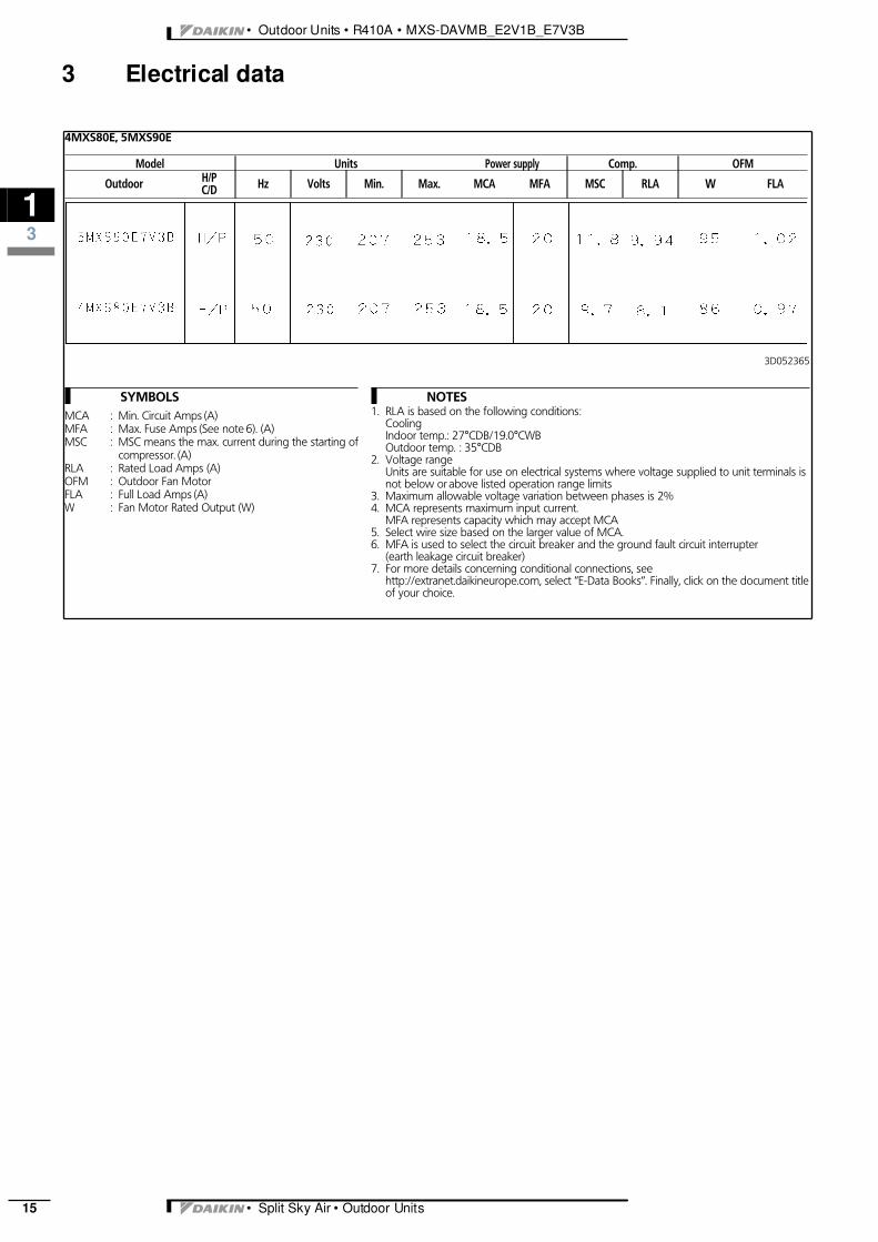
SYMBOLSMCA : Min. Circuit Amps (A)MFA : Max. Fuse Amps (See note 6). (A)MSC : MSC means the max. current during the starting of
compressor. (A)RLA : Rated Load Amps (A)OFM : Outdoor Fan MotorFLA : Full Load Amps (A)W : Fan Motor Rated Output (W)
NOTES1. RLA is based on the following conditions:
CoolingIndoor temp.: 27°CDB/19.0°CWBOutdoor temp. : 35°CDB
2. Voltage rangeUnits are suitable for use on electrical systems where voltage supplied to unit terminals isnot below or above listed operation range limits
3. Maximum allowable voltage variation between phases is 2%4. MCA represents maximum input current.
MFA represents capacity which may accept MCA5. Select wire size based on the larger value of MCA.6. MFA is used to select the circuit breaker and the ground fault circuit interrupter
(earth leakage circuit breaker)7. For more details concerning conditional connections, see
http://extranet.daikineurope.com, select ’’E-Data Books’’. Finally, click on the document titleof your choice.
4MXS80E, 5MXS90E
Model Units Power supply Comp. OFM
Outdoor H/PC/D Hz Volts Min. Max. MCA MFA MSC RLA W FLA

3
14
• Split Sky Air • Outdoor Units 16
• Outdoor Units • R410A • MXS-DAVMB_E2V1B_E7V3B
4 Options
4MXS, 5MXS
N° Item 4MXS80E7 5MXS90E7 5MKS90E71 Drain plug KKPJ5F180
4TW27571-1
• Outdoor Units • R410A • MXS-DAVMB_E2V1B_E7V3B
16
• Split Sky Air • Outdoor Units389
6 Dimensional drawing & centre of gravity6 - 1 Dimensional drawing
3D039391A
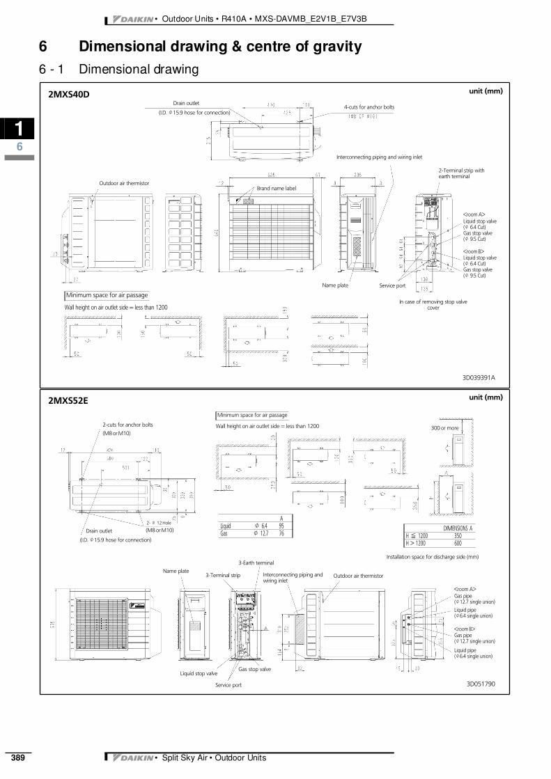
2MXS40D unit (mm)
4-cuts for anchor boltsDrain outlet
(I.D. J15.9 hose for connection)
Interconnecting piping and wiring inlet
2-Terminal strip withearth terminal
Name plate
<room A>Liquid stop valve(J 6.4 Cut)Gas stop valve(J 9.5 Cut)
<room B>Liquid stop valve(J 6.4 Cut)Gas stop valve(J 9.5 Cut)
Minimum space for air passage
Wall height on air outlet side = less than 1200
Outdoor air thermistor
Service port
In case of removing stop valvecover
Brand name label
3D051790
2MXS52E
ALiquid J 6.4 95Gas J 12.7 76
unit (mm)
2-cuts for anchor bolts
Drain outlet
(I.D. J15.9 hose for connection)
Interconnecting piping andwiring inlet
3-Earth terminalName plate
<room A>Gas pipe(J12.7 single union)Liquid pipe(J6.4 single union)
<room B>Gas pipe(J12.7 single union)
Liquid pipe(J6.4 single union)
(M8 or M10)
Minimum space for air passage
Wall height on air outlet side = less than 1200
Outdoor air thermistor
Liquid stop valve
Service port
Gas stop valve
3-Terminal strip
2- J 12 Hole
(M8 or M10) DIMENSIONS AH % 1200 350H > 1200 600
Installation space for discharge side (mm)
300 or more
3
16
• Split Sky Air • Outdoor Units 390
• Outdoor Units • R410A • MXS-DAVMB_E2V1B_E7V3B
6 Dimensional drawing & centre of gravity6 - 1 Dimensional drawing
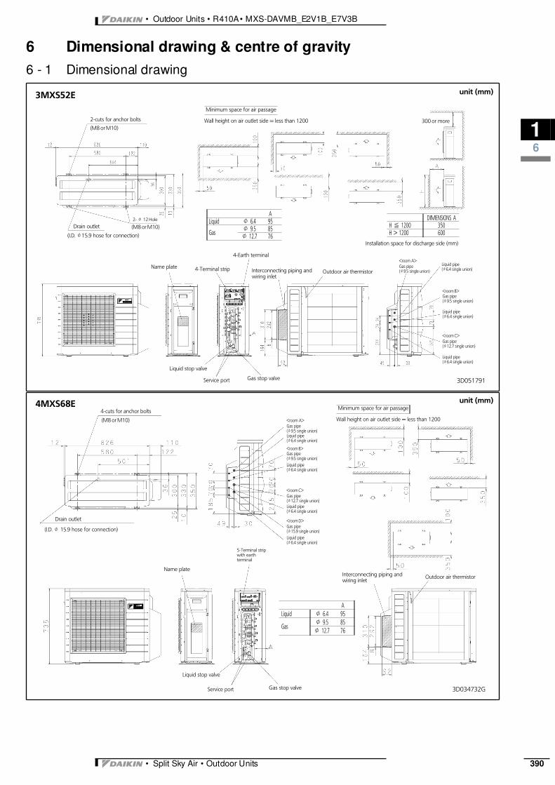
3D051791
3MXS52E
ALiquid J 6.4 95
Gas J 9.5 85J 12.7 76
unit (mm)
2-cuts for anchor bolts
Drain outlet
(I.D. J15.9 hose for connection)
Interconnecting piping andwiring inlet
4-Earth terminal
Name plate
<room B>Gas pipe(J9.5 single union)
Liquid pipe(J6.4 single union)
<room C>Gas pipe(J12.7 single union)
Liquid pipe(J6.4 single union)
(M8 or M10)
Minimum space for air passage
Wall height on air outlet side = less than 1200
Outdoor air thermistor
Liquid stop valve
Service port Gas stop valve
4-Terminal strip
2- J 12 Hole
(M8 or M10)
DIMENSIONS AH % 1200 350H > 1200 600
Installation space for discharge side (mm)
300 or more
<room A>Gas pipe(J9.5 single union)
Liquid pipe(J6.4 single union)
3D034732G
4MXS68E
ALiquid J 6.4 95
GasJ 9.5 85J 12.7 76
unit (mm)4-cuts for anchor bolts
Drain outlet
(I.D. J 15.9 hose for connection)
Interconnecting piping andwiring inlet
5-Terminal stripwith earthterminal
Name plate
<room A>Gas pipe(J9.5 single union)Liquid pipe(J6.4 single union)
<room B>Gas pipe(J9.5 single union)Liquid pipe(J6.4 single union)
<room C>Gas pipe(J12.7 single union)Liquid pipe(J6.4 single union)
<room D>Gas pipe(J15.9 single union)Liquid pipe(J6.4 single union)
(M8 or M10)
Minimum space for air passage
Wall height on air outlet side = less than 1200
Outdoor air thermistor
Liquid stop valve
Service port Gas stop valve
• Outdoor Units • R410A • MXS-DAVMB_E2V1B_E7V3B
16
• Split Sky Air • Outdoor Units391
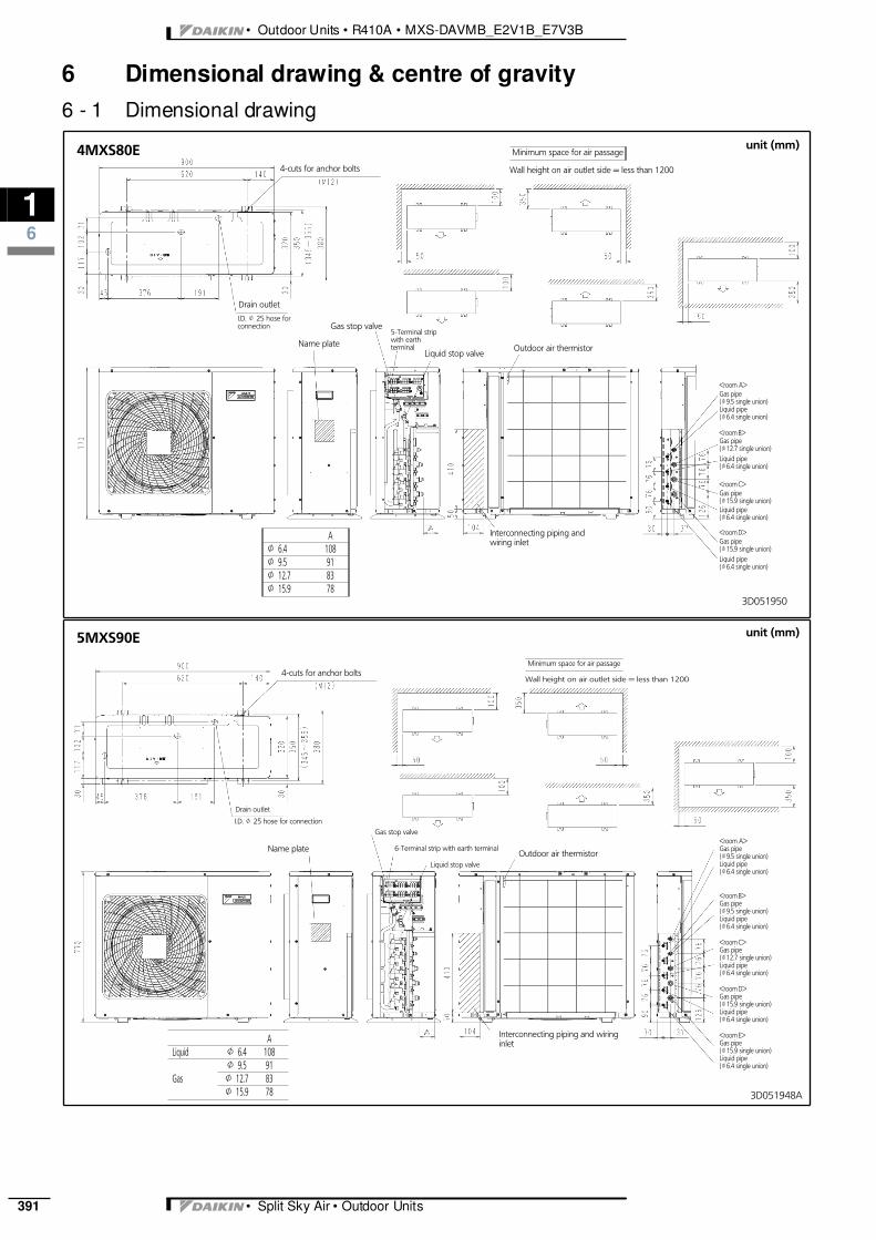
6 Dimensional drawing & centre of gravity6 - 1 Dimensional drawing
3D051950
4MXS80E
AJ 6.4 108J 9.5 91J 12.7 83J 15.9 78
unit (mm)
4-cuts for anchor bolts
Drain outlet
I.D. J 25 hose forconnection
Interconnecting piping andwiring inlet
5-Terminal stripwith earthterminalName plate
<room A>Gas pipe(J9.5 single union)Liquid pipe(J6.4 single union)
<room B>Gas pipe(J12.7 single union)Liquid pipe(J6.4 single union)
<room C>Gas pipe(J15.9 single union)Liquid pipe(J6.4 single union)
<room D>Gas pipe(J15.9 single union)Liquid pipe(J6.4 single union)
Minimum space for air passage
Wall height on air outlet side = less than 1200
Outdoor air thermistorLiquid stop valve
Gas stop valve
3D051948A
5MXS90E
ALiquid J 6.4 108
GasJ 9.5 91J 12.7 83J 15.9 78
unit (mm)
4-cuts for anchor bolts
Drain outlet
I.D. J 25 hose for connection
Interconnecting piping and wiringinlet
6-Terminal strip with earth terminalName plate<room A>Gas pipe(J9.5 single union)Liquid pipe(J6.4 single union)
<room B>Gas pipe(J9.5 single union)Liquid pipe(J6.4 single union)
<room C>Gas pipe(J12.7 single union)Liquid pipe(J6.4 single union)
<room D>Gas pipe(J15.9 single union)Liquid pipe(J6.4 single union)
<room E>Gas pipe(J15.9 single union)Liquid pipe(J6.4 single union)
Minimum space for air passage
Wall height on air outlet side = less than 1200
Outdoor air thermistorLiquid stop valve
Gas stop valve

3
16
• Split Sky Air • Outdoor Units 392
• Outdoor Units • R410A • MXS-DAVMB_E2V1B_E7V3B
6 Dimensional drawing & centre of gravity6 - 2 Centre of gravity
4D040369A
2MXS40D
Anchor bolt
4D037024H
2MXS52E, 3MXS52E, 4MXS68E
Anchor bolt

• Outdoor Units • R410A • MXS-DAVMB_E2V1B_E7V3B
16
• Split Sky Air • Outdoor Units393
6 Dimensional drawing & centre of gravity6 - 2 Centre of gravity
4D052059
4MXS80E, 5MXS90E
Anchor bolt
3
17
• Split Sky Air • Outdoor Units 394
• Outdoor Units • R410A • MXS-DAVMB_E2V1B_E7V3B
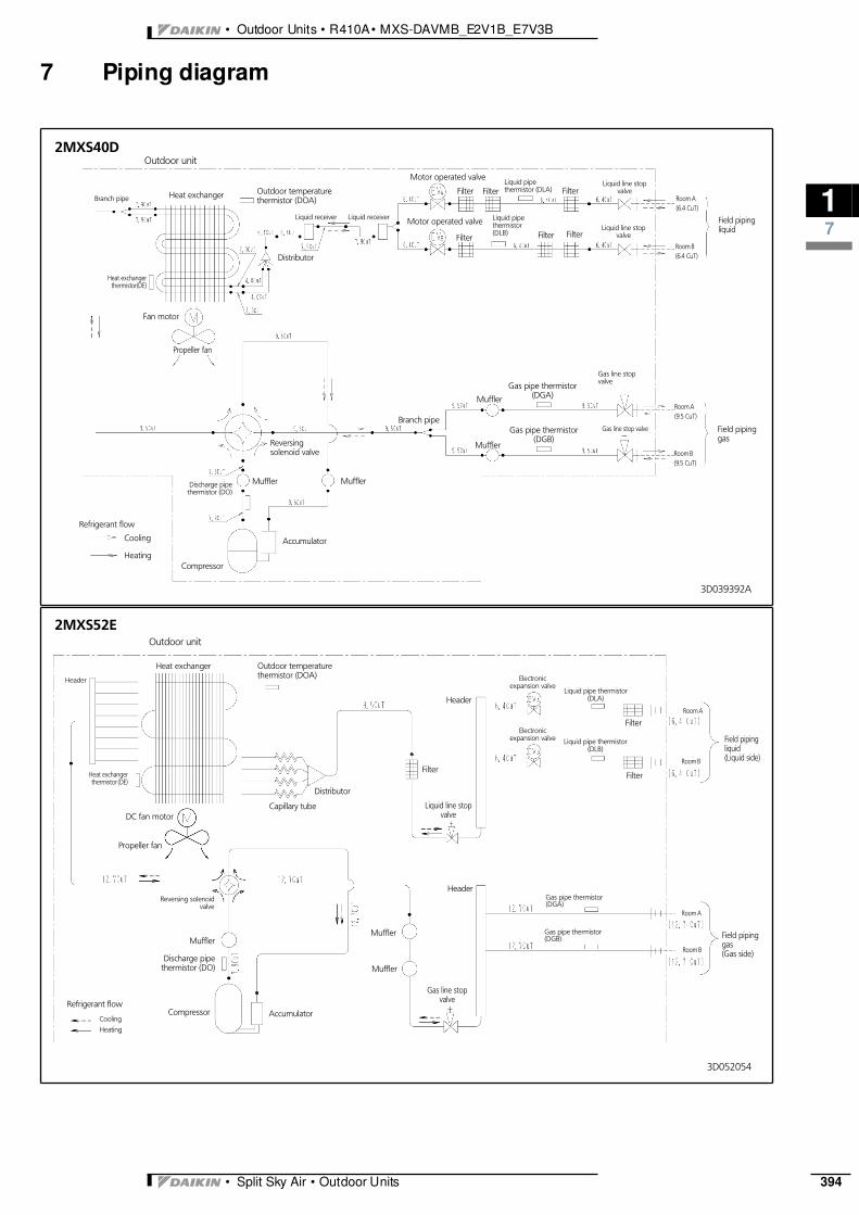
7 Piping diagram
3D039392A
2MXS40D
Heat exchanger Room A(6.4 CuT)
Room B(6.4 CuT)
Filter
Field pipingliquid
Field pipinggas
Room A(9.5 CuT)
Room B(9.5 CuT)
Gas line stop valve
FilterFilter Filter
Heat exchangerthermistor(DE)
Motor operated valve
Motor operated valve
Outdoor temperaturethermistor (DOA)
Propeller fan
Gas line stopvalve
Filter
Reversingsolenoid valve
Gas pipe thermistor(DGA)
Discharge pipethermistor (DO)
Compressor
Muffler
Refrigerant flow
Gas pipe thermistor(DGB)
Filter
Branch pipe
Outdoor unit
Accumulator
Fan motor
Distributor
Muffler
Liquid line stopvalve
Branch pipe
Muffler
Muffler
Liquid line stopvalve
Cooling
Heating
Liquid receiver Liquid receiver
Liquid pipethermistor (DLA)
Liquid pipethermistor(DLB)
3D052054
2MXS52E
Heat exchanger
Room A
Room B
Field pipingliquid(Liquid side)
Field pipinggas(Gas side)
Room A
Room B
Filter
FilterHeat exchangerthermistor (DE)
Electronicexpansion valve
Electronicexpansion valve
Filter
Outdoor temperaturethermistor (DOA)
Propeller fan
Gas line stopvalve
Gas pipe thermistor(DGA)
Gas pipe thermistor(DGB)
Discharge pipethermistor (DO)
CompressorRefrigerant flow
Outdoor unit
Accumulator
DC fan motor
Distributor
Capillary tube
Liquid pipe thermistor(DLA)
Liquid pipe thermistor(DLB)
Liquid line stopvalve
Cooling
Heating
Header
HeaderReversing solenoid
valve
Muffler
Header
Muffler
Muffler

• Outdoor Units • R410A • MXS-DAVMB_E2V1B_E7V3B
17
• Split Sky Air • Outdoor Units395
7 Piping diagram
3D052055
3MXS52E
Heat exchanger
Room A
Room B
Room C
Field pipingliquid(Liquid side)
Field pipinggas(Gas side)
Room A
Room B
Room C
Filter
Filter
FilterHeat exchangerthermistor (DE)
Electronic expansionvalve
Electronic expansionvalve
Electronic expansionvalve
Filter
Outdoor temperaturethermistor (DOA)
Propeller fan
Gas line stopvalve
Gas pipe thermistor(DGA)
Gas pipe thermistor(DGB)
Gas pipe thermistor(DGC)
Discharge pipethermistor (DO)
CompressorRefrigerant flow
Outdoor unit
Accumulator
DC fan motor
Distributor
Capillary tube
Liquid pipethermistor (DLA)
Liquid pipethermistor (DLB)
Liquid pipethermistor (DLC)
Liquid line stopvalve
Cooling
Heating
Header
Header
Reversing solenoidvalve
Muffler
Header
Muffler
Muffler
3D034511G
4MXS68E
Heat exchanger
Room A
Room B
Room C
Field pipingliquid(Liquid side)
Field pipinggas(Gas side)
Room A
Room B
Room C
Filter
Filter
Filter
Heat exchangerthermistor (DE)
Electronic expansion valve
Electronic expansion valve
Electronic expansion valve
Filter
Outdoor temperaturethermistor (DOA)
Propeller fan
Gas line stopvalve
Gas pipe thermistor(DGA)
Gas pipe thermistor(DGB)
Gas pipe thermistor(DGC)Discharge pipe
thermistor (DO)
CompressorRefrigerant flow Room C
Outdoor unit
Accumulator
DC fan motor
Distributor
Capillary tube
Liquid pipethermistor (DLA)
Liquid pipethermistor (DLB)
Liquid pipethermistor (DLC)
Liquid line stopvalve
Cooling
Heating
Header
Header
Reversing solenoidvalve
Muffler
Header
Electronic expansion valveLiquid pipe
thermistor (DLD)
Filter
Room C
Gas pipe thermistor(DGD)
Accumulator
Defrostsolenoidvalve

3
17
• Split Sky Air • Outdoor Units 396
• Outdoor Units • R410A • MXS-DAVMB_E2V1B_E7V3B
7 Piping diagram
4MXS80E
3D051937B
Heat exchanger
Room A
Room B
Room C
Field pipingliquid
Field pipinggas
Room A
Room B
Room C
Filter
Filter
Filter
Heat exchanger thermistor(Condenser)
Motor operated valve (A)
Motor operated valve (B)
Motor operated valve (C)
Filter
Outdoor temperaturethermistor
Propeller fan
Gas line stopvalve
Gas pipe thermistor(Room-A)
Gas pipe thermistor(Room-B)
Gas pipe thermistor(Room-C)
Motor operated valve (D)
Discharge pipethermistor
CompressorAccumulator
Refrigerant flow
Gas pipe thermistor(Room-D)
Filter
Room D
Room D
Outdoor unit
Accumulator
DC fan motor Distributor
Capillary tube
Liquid pipe thermistor(Room-A)
Liquid pipe thermistor(Room-B)
Liquid pipe thermistor(Room-C)
Liquid pipe thermistor(Room-D)
Liquid line stopvalve
CoolingHeating
Header
HeaderReceiver
Header
Muffler
4-way valve
Motor operated valve (E)
Muffler Muffler
5MXS90E
3D051936A
Heat exchanger
Room A
Room B
Room CField pipingliquid
Field pipinggas
Room A
Room B
Room C
Filter
Filter
Filter
Heat exchanger thermistor(Condenser)
Motor operated valve (A)
Motor operated valve (B)
Motor operated valve (C)
Filter
Outdoor temperaturethermistor
Propeller fan
Gas line stop valve
Gas pipe thermistor(Room-A)
Gas pipe thermistor(Room-B)
Gas pipe thermistor(Room-C)
Motor operated valve (D)
Discharge pipethermistor
CompressorAccumulator
Refrigerant flow
Gas pipe thermistor(Room-D)
Filter
Room D
Room D
Outdoor unit
Accumulator
DC fan motor Distributor
Capillary tube
Liquid pipe thermistor (Room-A)
Liquid pipe thermistor (Room-B)
Liquid pipe thermistor (Room-C)
Liquid pipe thermistor (Room-D)
Liquid line stop valve
CoolingHeating
Header
Header
Receiver
Header
Muffler
4-way valve
Room E
Room E
Motor operated valve (E)
Filter
Liquid pipe thermistor (Room-E)
Gas pipe thermistor(Room-E)
Muffler Muffler
• Outdoor Units • R410A • MXS-DAVMB_E2V1B_E7V3B
18
• Split Sky Air • Outdoor Units397
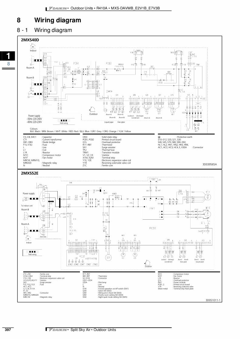
8 Wiring diagram8 - 1 Wiring diagram
3D039565A
2MXS40D
C5∼C8, SHC1 : CapacitorCT1 : Current transformerDB1, DB3 : Diode bridgeF1U∼F3U : FuseL : LiveL1 : CoilL1R : ReactorM1C : Compressor motorM1F : Fan motorMRCW, MRM10,MRM20 : Magnetic relayN : Neutral
OIS3 : Solid state relayPCB1, PCB2 : Printed circuit boardQ1L : Overload protectorR1T∼R8T : ThermistorSA1 : Surge arresterTFU : Thermal fuseTRM1 : Transistor moduleV1, V2, V3 : VaristorX1M, X2M : Terminal stripY1E, Y2E : Electronic expansion valve coilY1R : Reversing solenoide valve coilZ1C : Ferrite core
gField wiring
R : Protective earthS10∼S12, S20, S21, S30S40, S45, S70, S80, S90∼S92,HL1, HL2, HN1, HN2, HR3, HR4,AC1, AC2, HC3, HC4, E, X30A : Connector
Power supply∼50Hz 220-240V∼60Hz 220-230V
Indoor
Room B
Room A
(Room A)
(condenser)(discharge)
(Room B)(outdoor)
(Room A) (Room B)
Gas pipe
Outdoor (Room A)
(Room B)
Liquid pipe
ColoursBLK: Black / BRN: Brown / WHT: White / RED: Red / BLU: Blue / GRY: Grey / ORG: Orange / YLW: Yellow
3D051011-1
2MXS52E
Z1C∼Z3C : Ferrite coreX1M∼X3M : Terminal stripY1E∼Y3E : Electronic expansion valve coilV2,V3,V5,V6,V11 : VaristorSA2 : Surge arresterFU1, FU2, FU3 : FuseAC1, AC2U, V, W, X11AE1, E2HR1, HR2 : ConnectorMRM10, MRM20MRC/W : Magnetic relay
R1T∼R5TR8T, R9T : ThermistorS2∼S102 : ConnectorLED1∼LED4LEDA : Pilot lampL : LiveN : NeutralS1W : Forced operation on/off switch (SW1)S2W : Select SW (SW2)S3W : Wiring error check SW (SW3)S4W : Priority room setting SW (SW4)S5W : Night quiet mode setting SW (SW5)
gField wiring
M1C : Compressor motorM1F : Fan motorL1R : ReactorQ1L : Overload protectorPM1 : Power modulePCB1, 2 : Printed circuit boardY1R : Reversing solenoid valveSheet metal : Terminal strip fixed plate
Power supply
To indoor unit
Room B
Room A
(Room B)(Room A)(condenser)
(discharge)(Gas pipe)
(outdoor) (Room A) (Room B)(Liquid pipe)
Indoor
Outdoor
Sheet metal

3
18
• Split Sky Air • Outdoor Units 398
• Outdoor Units • R410A • MXS-DAVMB_E2V1B_E7V3B
8 Wiring diagram8 - 1 Wiring diagram
3D051012-1
3MXS52E
Z1C∼Z3C : Ferrite coreX1M∼X4M : Terminal stripY1E∼Y3E : Electronic expansion valve coilV2,V3,V5,V6,V11 : VaristorSA2 : Surge arresterFU1, FU2, FU3 : FuseAC1, AC2U, V, W, X11AE1, E2HR1, HR2 : ConnectorMRM10, MRM20MRC/W : Magnetic relay
R1T∼R6TR8T∼R10T : ThermistorS2∼S102 : ConnectorLED1∼LED4LEDA : Pilot lampL : LiveN : NeutralS1W : Forced operation on/off switch (SW1)S2W : Select SW (SW2)S3W : Wiring error check SW (SW3)S4W : Priority room setting SW (SW4)S5W : Night quiet mode setting SW (SW5)
gField wiring
M1C : Compressor motorM1F : Fan motorL1R : ReactorQ1L : Overload protectorPM1 : Power modulePCB1, 2 : Printed circuit boardY1R : Reversing solenoid valveSheet metal : Terminal strip fixed plate
Power supply
To indoor unit
Room B
Room A
(Room C)(Room A)
(condenser)
(discharge)
(Gas pipe)
(outdoor) (Room A) (Room C)
(Liquid pipe)
Indoor
Outdoor
Sheet metal
Room C
(Room B) (Room B)
3D034312J
4MXS68E
Z1C∼Z3C : Ferrite coreX1M∼X5M : Terminal stripY1E∼Y4E : Electronic expansion valve coilV2∼V5 : VaristorFU1, FU2, FU201 : FuseHE, HL, HNE, AC1, AC2H1, H2, L1L2 : ConnectorMRM10, MRM20MRB, MRDMRC/W : Magnetic relay
R1T∼R12T : ThermistorS2∼S102 : ConnectorH1P∼H5P : Pilot lampL : LiveN : NeutralS1W : Forced operation on/off switch (SW1)S2W : Select SW (SW2)S3W : Wiring error check SW (SW3)S4W : Priority room setting SW (SW4)S5W : Night quiet mode setting SW (SW5)SA1 : Surge arresterY1R : Reversing solenoid valve
gField wiring
Y1S : Defrost solenoid valve coilPCB : Printed circuit boardDB1 : Diode bridgeM1C : Compressor motorM1F : Fan motorL1R : ReactorQ1L : Overload protectorCT1 : Current transformerMID1∼MID2 : Molded interconnect deviceSPM : System power module
To indoor unit
Room B
Room A
(Room C)(Room A)
(condenser)
(discharge)
(Gas pipe)
(outdoor) (Room A) (Room C)
(Liquid pipe)
Room D
Room C
(Room B) (Room B)(Room D) (Room D)

• Outdoor Units • R410A • MXS-DAVMB_E2V1B_E7V3B
18
• Split Sky Air • Outdoor Units399
8 Wiring diagram8 - 1 Wiring diagram
2TW57576-1
4MXS80E
Z1C∼Z6C : Ferrite coreX1M∼X5M : Terminal stripY1E∼Y4E : Electronic expansion valve coilV2,V3,V5V9,V100 : VaristorSA2 : Surge arresterFU1, FU2, FU3 : FuseAC1,AC2U,V,W,X11AE1,E2EHR1,HR2 : ConnectorMRM10, MRM20MRC/W : Magnetic relay
R1T∼R3TR4T∼R7TR8T∼R11T : ThermistorS2∼S102 : ConnectorLED1∼LED4LEDA : Light emitting diodeSW1 : Forced operation on/off switch (SW1)SW2 : Operation mode sellect SW (SW2)SW3 : Wiring error check SW (SW3)SW4 : Priority room setting SW (SW4)SW5 : Night quiet mode setting SW (SW5)M1C : Compressor motorM1F : Fan motorL1R : Reactor
L: Live, N: Neutral, : Field wiring: Terminal strip : Connector : Connection
: Protective earth (screw) : Relay connector: Terminal
Q1L : Overload protectorPM1 : Power modulePCB1,2 : Printed circuit boardY1R : Four way valve coilSheet metal : Terminal strip fixed plateF2U : Field fuseQ1DI : Field earth leakage breaker
(300mA)
To indoor unit
Room C
Room B
Room A
Room
C
Room
A
Cond
ense
r
Disc
harg
e
Room
B
Out
door
Room
A
Room
C
Room
B
Room
D
Gas
pipe
Liqu
idpi
pe
Room D
Room
D
BLK: BlackBRN: brownWHT: WhiteRED: RedBLU: BlueGRY: GreyORG: OrangeYLW: YellowGRN: Green
Indoor Outdoor
Sheetmetal
2TW57586-1
5MXS90E
Z1C∼Z6C : Ferrite coreX1M∼X6M : Terminal stripY1E∼Y5E : Electronic expansion valve coilV2,V3,V5V9,V100 : VaristorSA2 : Surge arresterFU1, FU2, FU3 : FuseAC1,AC2U,V,W,X11AE1,E2EHR1,HR2H1, H2, L1, L2 : ConnectorMRM10, MRM20MRC/W : Magnetic relay
R1T∼R3TR4T∼R8TR9T∼R13T : ThermistorS2∼S102 : ConnectorLED1∼LED5LEDA : Light emitting diodeSW1 : Forced operation on/off switch (SW1)SW2 : Operation mode sellect SW (SW2)SW3 : Wiring error check SW (SW3)SW4 : Priority room setting SW (SW4)SW5 : Night quiet mode setting SW (SW5)M1C : Compressor motorM1F : Fan motorL1R : Reactor
L: Live, N: Neutral, : Field wiring: Terminal strip : Connector : Connection
: Protective earth (screw) : Relay connector: Terminal
Q1L : Overload protectorPM : Power modulePCB1,2 : Printed circuit boardY1R : Four way valve coilSheet metal : Terminal strip fixed plateF2U : Field fuseQ1DI : Field earth leakage breaker
(300mA)
To indoor unit
Room C
Room B
Room A
Room
A
Room
B
Room
C
Room
D
Room
E
Room
A
Room
B
Room
C
Room
D
Room
E
Cond
ense
r
Disc
harg
e
Out
door
Gas
pipe
Liqu
idpi
pe
Room D
BLK: BlackBRN: brownWHT: WhiteRED: RedBLU: BlueGRY: GreyORG: OrangeYLW: YellowGRN: Green
Room E
Indoor Outdoor
Sheetmetal

3
19
• Split Sky Air • Outdoor Units 400
• Outdoor Units • R410A • MXS-DAVMB_E2V1B_E7V3B
9 Sound data9 - 1 Sound pressure spectrum
3D040367A
Oct
ave
band
soun
dpr
essu
rele
vel
dB:(0
dB=
0.00
02µ
bar)
Octave band center frequency (Hz)
2MXS40D (Cooling)
Legend
50/60Hz, 220-240/220-230V
approximatethreshold hearing
for continuousnoise
NOTES1 Operation sound is measured in an anechoic
chamber.2 Operation sound level differs with operation and
ambient conditions.3 Reference acoustic pressure 0dB = 20µPa
Legend
50/60Hz, 220-240/220-230V
NOTES1 Operation sound is measured in an anechoic
chamber.2 Operation sound level differs with operation and
ambient conditions.3 Reference acoustic pressure 0dB = 20µPa
2MXS40D (Heating)
Oct
ave
band
soun
dpr
essu
rele
vel
dB:(0
dB=
0.00
02µ
bar)
approximatethreshold hearing for
continuous noise
3D040367A Octave band center frequency (Hz)
3D034807F
Oct
ave
band
soun
dpr
essu
rele
vel
dB:(0
dB=
0.00
02µ
bar)
Octave band center frequency (Hz)
4MXS68E (Cooling)
approximatethreshold hearing for
continuous noise
NOTES1 Operation sound is measured in an anechoic chamber.2 Operation sound level differs with operation and ambient conditions.3 The operation noise measuring method is in accordance with
JISC9612
NOTES1 Operation sound is measured in an anechoic chamber.2 Operation sound level differs with operation and ambient conditions.3 The operation noise measuring method is in accordance with
JISC9612
4MXS68E (Heating)
Oct
ave
band
soun
dpr
essu
rele
vel
dB:(0
dB=
0.00
02µ
bar)
approximatethreshold hearing
for continuousnoise
3D034807FOctave band center frequency (Hz)

• Outdoor Units • R410A • MXS-DAVMB_E2V1B_E7V3B
19
• Split Sky Air • Outdoor Units401
9 Sound data9 - 1 Sound pressure spectrum
3D052303
Oct
ave
band
soun
dpr
essu
rele
vel
dB:(0
dB=
0.00
02µ
bar)
Octave band center frequency (Hz)
4MXS80E (Cooling)
approximatethreshold hearing for
continuous noise
NOTES1 Operation sound is measured in an anechoic chamber.2 Operation sound level differs with operation and ambient conditions.3 The operation noise measuring method is in accordance with
JISC9612
NOTES1 Operation sound is measured in an anechoic chamber.2 Operation sound level differs with operation and ambient conditions.3 The operation noise measuring method is in accordance with
JISC9612
4MXS80E (Heating)
Oct
ave
band
soun
dpr
essu
rele
vel
dB:(0
dB=
0.00
02µ
bar)
approximatethreshold hearing
for continuousnoise
3D052303Octave band center frequency (Hz)
3D052302
Oct
ave
band
soun
dpr
essu
rele
vel
dB:(0
dB=
0.00
02µ
bar)
Octave band center frequency (Hz)
5MXS90E (Cooling)
approximatethreshold hearing for
continuous noise
NOTES1 Operation sound is measured in an anechoic chamber.2 Operation sound level differs with operation and ambient conditions.3 The operation noise measuring method is in accordance with
JISC9612
NOTES1 Operation sound is measured in an anechoic chamber.2 Operation sound level differs with operation and ambient conditions.3 The operation noise measuring method is in accordance with
JISC9612
5MXS90E (Heating)
Oct
ave
band
soun
dpr
essu
rele
vel
dB:(0
dB=
0.00
02µ
bar)
approximatethreshold hearing for
continuous noise
3D052302Octave band center frequency (Hz)

3
19
• Split Sky Air • Outdoor Units 402
• Outdoor Units • R410A • MXS-DAVMB_E2V1B_E7V3B
9 Sound data9 - 2 Sound power spectrum
3TW27577-1
Oct
ave
band
soun
dpr
essu
rele
vel
dB:(0
dB=
0.00
02µ
bar)
Octave band center frequency (Hz)
4MXS80E
NOTES1 dB(A) = A-weighted sound power level (A-scale according to IEC)2 Reference acoustic intensity 0dB = 10E-6 µW/m2
3 Measured according to ISO 3744
3TW27597-1
Soun
dpo
wer
leve
l(dB)
Octave band center frequency (Hz)
5MXS90E
NOTES
1 dBA = A-weighted sound power level (A-scale accordingto IEC)
2 Refernece acoustic intensity 0dB = 10E-6µW/m_3 Measured according to ISO 3744
• Outdoor Units • R410A • MXS-DAVMB_E2V1B_E7V3B
110
• Split Sky Air • Outdoor Units403
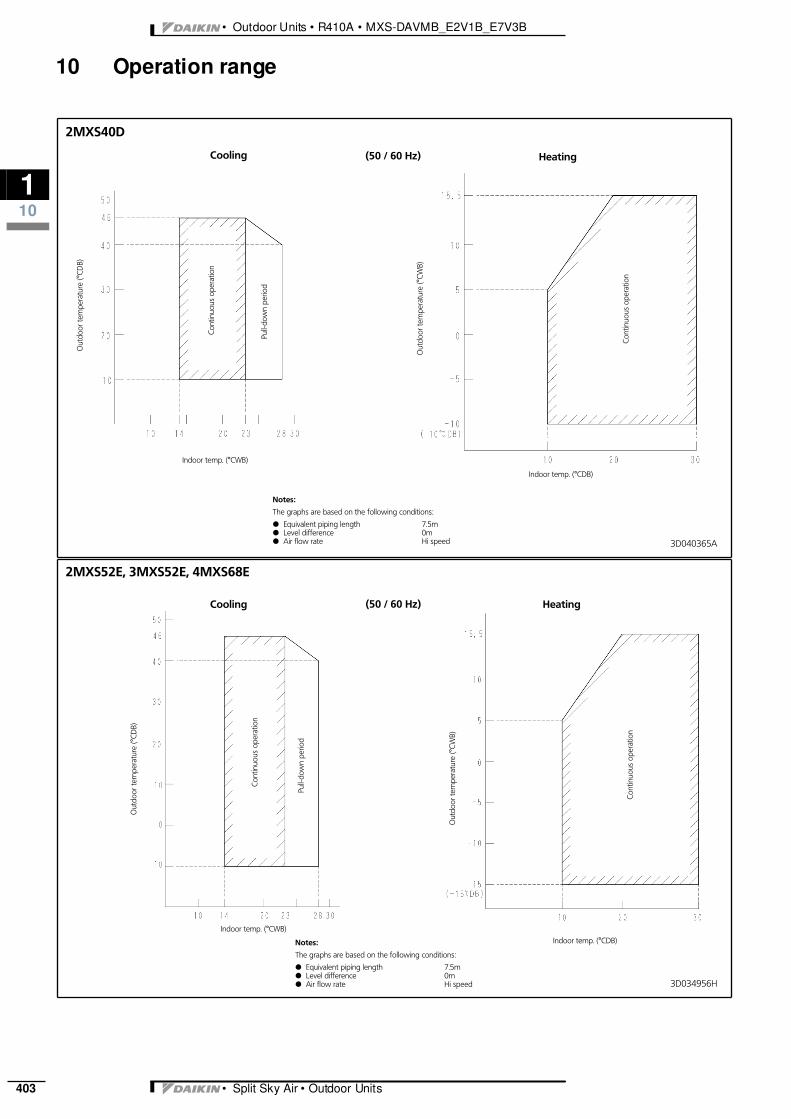
10 Operation range
3D040365A
Heating
2MXS40D
Cooling
Out
door
tem
pera
ture
(°CD
B)
Cont
inuo
usop
erat
ion
Pull-
dow
npe
riod
Out
door
tem
pera
ture
(°CW
B)
Cont
inuo
usop
erat
ion
Indoor temp. (°CWB)
Indoor temp. (°CDB)
Notes:
The graphs are based on the following conditions:
d Equivalent piping length 7.5md Level difference 0md Air flow rate Hi speed
(50 / 60 Hz)
Heating
2MXS52E, 3MXS52E, 4MXS68E
Cooling
Out
door
tem
pera
ture
(°CD
B)
Cont
inuo
usop
erat
ion
Pull-
dow
npe
riod
Out
door
tem
pera
ture
(°CW
B)
(50 / 60 Hz)
Cont
inuo
usop
erat
ion
Indoor temp. (°CWB)
Indoor temp. (°CDB)Notes:
The graphs are based on the following conditions:
d Equivalent piping length 7.5md Level difference 0md Air flow rate Hi speed 3D034956H

3
110
• Split Sky Air • Outdoor Units 404
• Outdoor Units • R410A • MXS-DAVMB_E2V1B_E7V3B
10 Operation range
Heating
4MXS80E, 5MXS90E
Cooling
Out
door
tem
pera
ture
(°CD
B)
Cont
inuo
usop
erat
ion
Pull-
dow
npe
riod
Out
door
tem
pera
ture
(°CW
B)
(50 / 60 Hz)
Cont
inuo
usop
erat
ion
Indoor temp. (°CWB)Indoor temp. (°CDB)
Notes:
The graphs are based on the following conditions:
d Equivalent piping length 7.5md Level difference 0md Air flow rate Hi speed 3D052043

• Outdoor Units • R410A • MXS-DAVMB_E2V1B_E7V3B
110
• Split Sky Air • Outdoor Units405
10 Operation range