my loop antenna - radio central amateur radio - rcarc loop antenna.pdf · my loop antenna november...
TRANSCRIPT
My Loop Antenna November 20, 2013 2
Outline
• Brief History
• Characteristics of Small Loop Antennas for HF
• My Loop for 40m – 15m
• Receive/Transmit Properties of Elect.-Small Loops
• Loop Equations
• Measuring Efficiency of a Loop or Vertical Antenna
• Evaluation of My Loop – Comparison to Verticals
• Conclusions - References
My Loop Antenna November 20, 2013 3
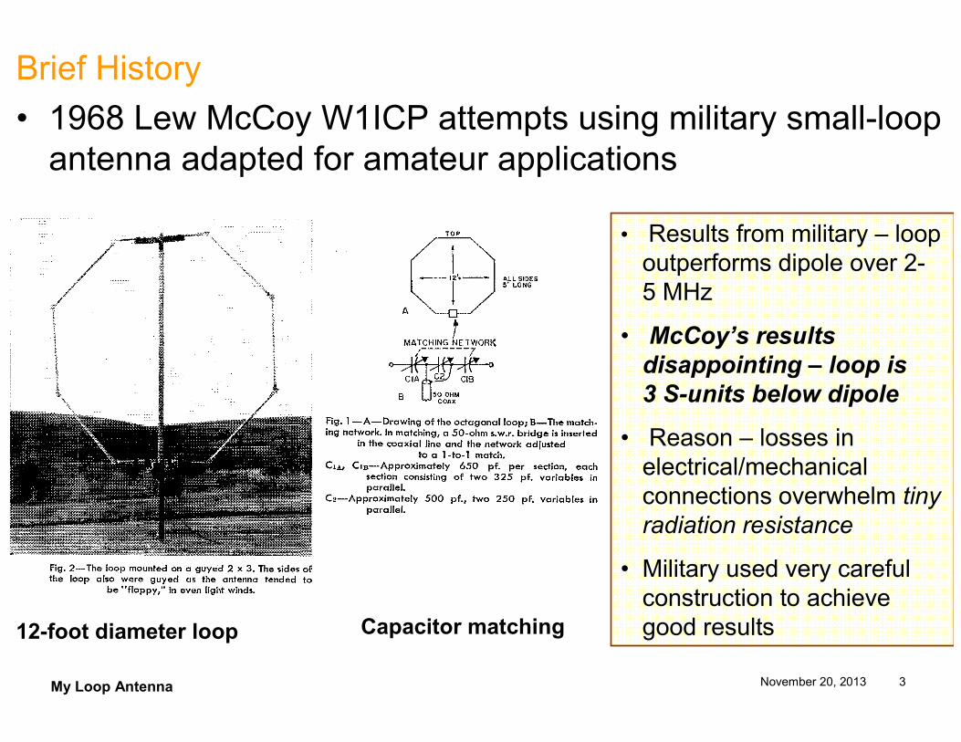
Brief History
• 1968 Lew McCoy W1ICP attempts using military small-loop antenna adapted for amateur applications
12-foot diameter loop Capacitor matching
• Results from military – loop outperforms dipole over 2-5 MHz
• McCoy’s results
disappointing – loop is
3 S-units below dipole
• Reason – losses in electrical/mechanical connections overwhelm tiny radiation resistance
• Military used very careful construction to achieve good results
My Loop Antenna November 20, 2013 4
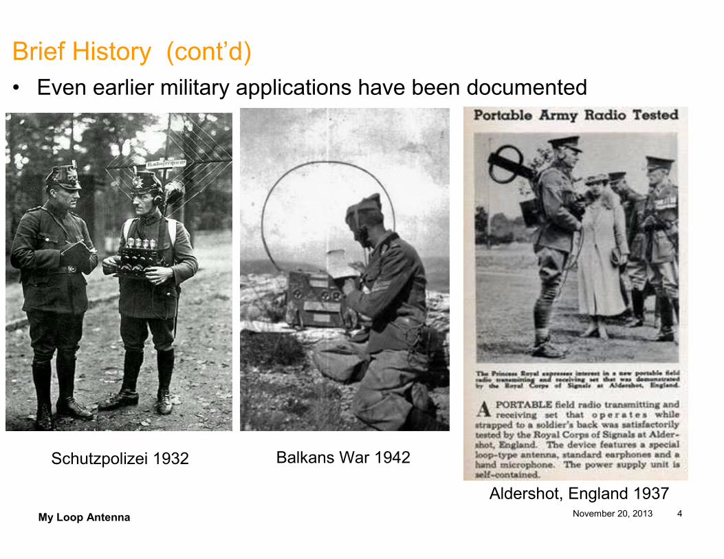
Brief History (cont’d)• Even earlier military applications have been documented
Schutzpolizei 1932 Balkans War 1942
Aldershot, England 1937
My Loop Antenna November 20, 2013 5
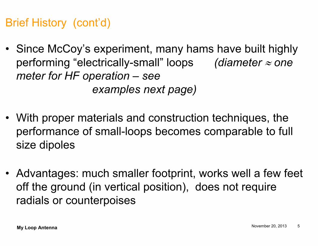
Brief History (cont’d)
• Since McCoy’s experiment, many hams have built highly performing “electrically-small” loops (diameter ≈ one meter for HF operation – see
examples next page)
• With proper materials and construction techniques, the performance of small-loops becomes comparable to full size dipoles
• Advantages: much smaller footprint, works well a few feet off the ground (in vertical position), does not require radials or counterpoises
My Loop Antenna November 20, 2013 6
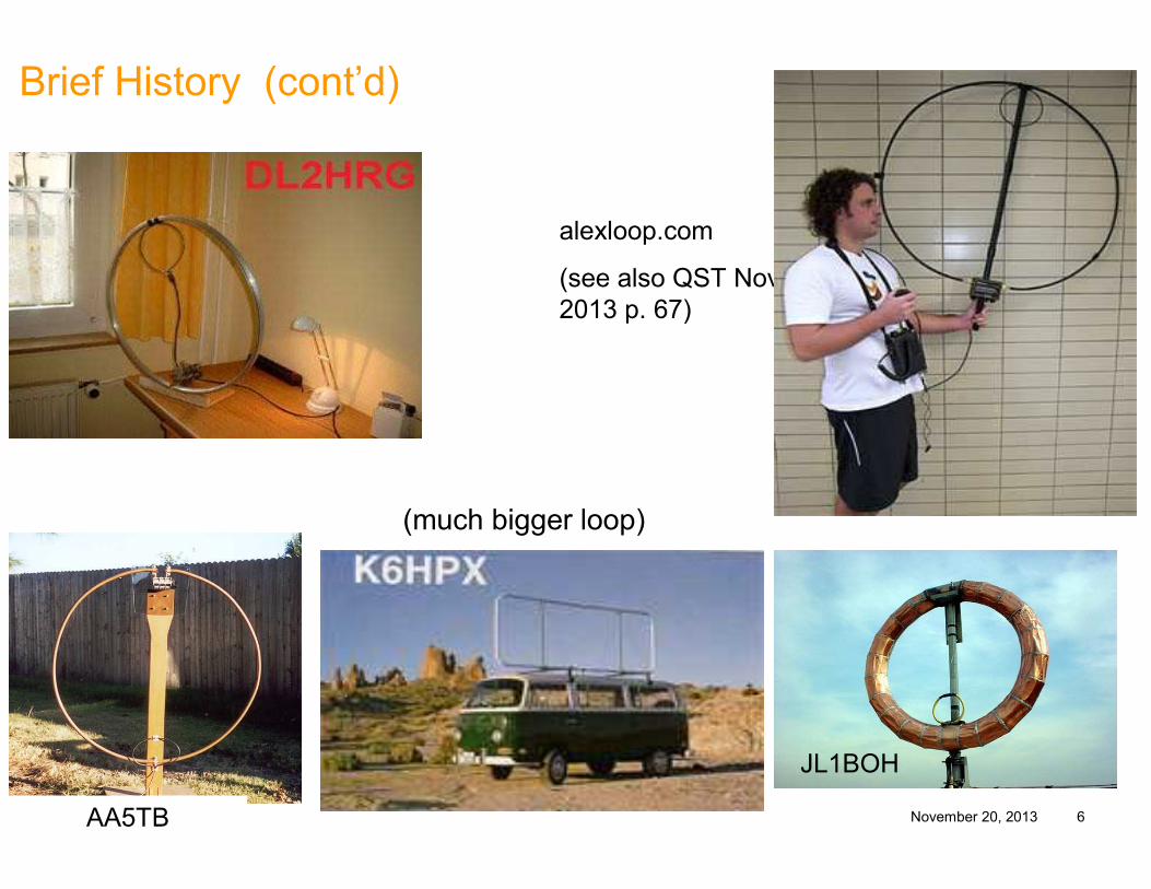
Brief History (cont’d)
JL1BOH
AA5TB
alexloop.com
(see also QST Nov. 2013 p. 67)
(much bigger loop)
My Loop Antenna November 20, 2013 7
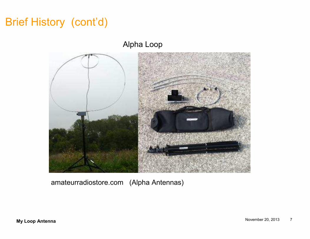
Brief History (cont’d)
amateurradiostore.com (Alpha Antennas)
Alpha Loop
My Loop Antenna November 20, 2013 8
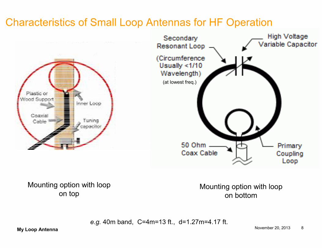
Characteristics of Small Loop Antennas for HF Operation
e.g. 40m band, C=4m=13 ft., d=1.27m=4.17 ft.
(at lowest freq.)
Mounting option with loop on top
Mounting option with loop on bottom
My Loop Antenna November 20, 2013 9
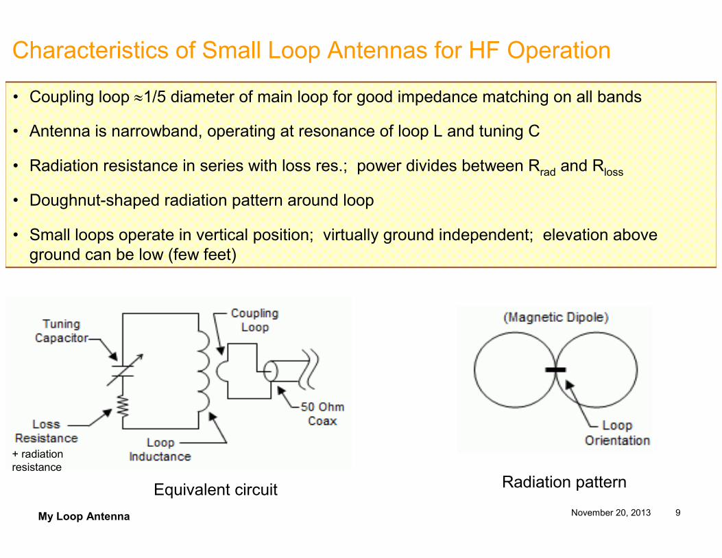
Characteristics of Small Loop Antennas for HF Operation
• Coupling loop ≈1/5 diameter of main loop for good impedance matching on all bands
• Antenna is narrowband, operating at resonance of loop L and tuning C
• Radiation resistance in series with loss res.; power divides between Rrad and Rloss
• Doughnut-shaped radiation pattern around loop
• Small loops operate in vertical position; virtually ground independent; elevation above ground can be low (few feet)
Equivalent circuit Radiation pattern
+ radiation resistance
My Loop Antenna November 20, 2013 10
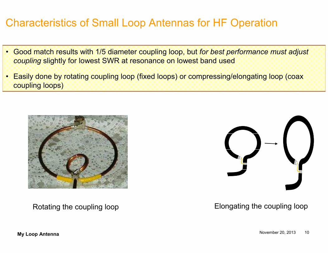
Characteristics of Small Loop Antennas for HF Operation
• Good match results with 1/5 diameter coupling loop, but for best performance must adjust coupling slightly for lowest SWR at resonance on lowest band used
• Easily done by rotating coupling loop (fixed loops) or compressing/elongating loop (coax coupling loops)
Rotating the coupling loop Elongating the coupling loop
My Loop Antenna November 20, 2013 11
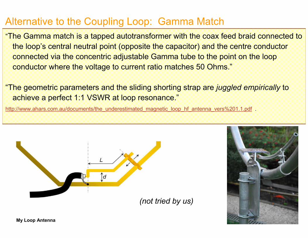
Alternative to the Coupling Loop: Gamma Match“The Gamma match is a tapped autotransformer with the coax feed braid connected to the loop’s central neutral point (opposite the capacitor) and the centre conductor connected via the concentric adjustable Gamma tube to the point on the loop conductor where the voltage to current ratio matches 50 Ohms.”
“The geometric parameters and the sliding shorting strap are juggled empirically to achieve a perfect 1:1 VSWR at loop resonance.”
http://www.ahars.com.au/documents/the_underestimated_magnetic_loop_hf_antenna_vers%201.1.pdf .
(not tried by us)
My Loop Antenna November 20, 2013 12
Characteristics of Small Loop Antennas for HF Operation
• The tuning capacitor experiences very high voltage even at low power levels
• For my loop: 5W – 800v 50W – 2500v 100W – 3600v
• Must choose capacitor carefully
• Sliding contact to capacitor’s rotor are lossy relative to the very small radiation resistance of loop antenna
• Preferred capacitors are butterfly, split stator, vacuum types
My Loop Antenna November 20, 2013 13
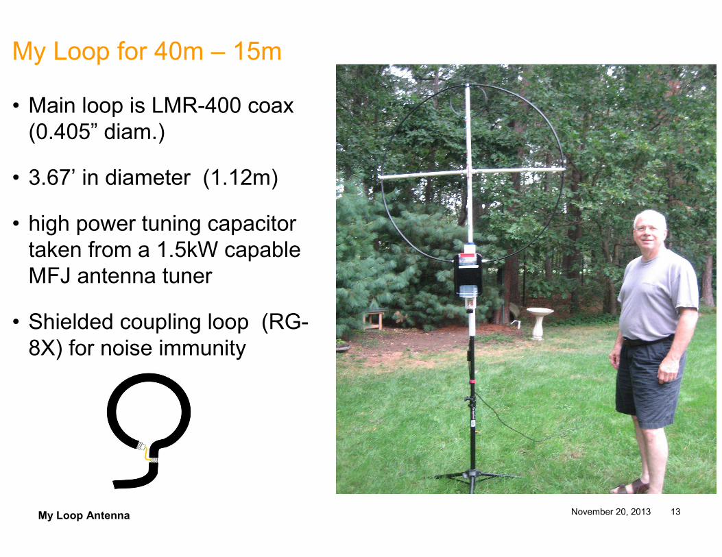
My Loop for 40m – 15m
• Main loop is LMR-400 coax (0.405” diam.)
• 3.67’ in diameter (1.12m)
• high power tuning capacitor taken from a 1.5kW capable MFJ antenna tuner
• Shielded coupling loop (RG-8X) for noise immunity
My Loop Antenna November 20, 2013 14
Receive Properties of Electrically-Small Loops
• Loop antenna is tuned to a resonance on receive by adjusting the tuning capacitor
• Atmospheric noise dominates over receiver noise at HF
• Tuning is narrowband, tending to limit received noise
• Gain of a loop may be lower than that of other antennas, but what matters is the signal-to noise ratio
• Small loop antenna can produce a signal-to-noise ratio that is oftentimes better than a dipole for the same band
My Loop Antenna November 20, 2013 15
Transmit Properties of Electrically-Small Loops
• Small size achieved by virtue of construction
• High efficiency achieved by proper loop design.
• Resulting bandwidth is very narrow in an efficient loop
• Small loop antennas can be almost as efficient as dipole antennas over 20m – 10m; over 160m – 30m performance within one S-unit
• High efficiency require larger construction (e.g. 1” copper tubing)
• Portable loops (e.g. coax loop) less efficient but comparable toother portable antenna solutions (e.g. short verticals)
Transmit efficiency: the percentage of power applied to the antenna which is transmitted into the air.
My Loop Antenna November 20, 2013 16
Transmit Properties of Electrically-Small Loops (cont’d)
• Radiation resistance Rrad : that part of the antenna’s feedpoint resistance caused by the radiation of EM waves from the antenna
• Rrad is very small
• Ex: loop diam. 3.67 feet, loop conductor diam, 3 inches Rrad = 0.019 Ω (7 MHz) Rrad = 0.039 Ω (10.1 MHz)
• Ideal efficiency: 47% on 40m; 76% on 30m
• Loss due only to RF energy dissipated in the skin-depth of the loop conductor
• Actual efficiency will less because of contact resistance loss
My Loop Antenna November 20, 2013 17
Portable Loops – Evaluating Efficiency
• Goal: to build a portable loop: easily transportable and easy to set up
• Desired power handling ability 50W minimum CW (AlexLoop, Alpha Loop both rated at 10 watts CW)
• Will be less efficient than fixed-location loop with larger construction
• Will show that portable loop comparable in efficiency to other small and portable antennas
My Loop Antenna November 20, 2013 18
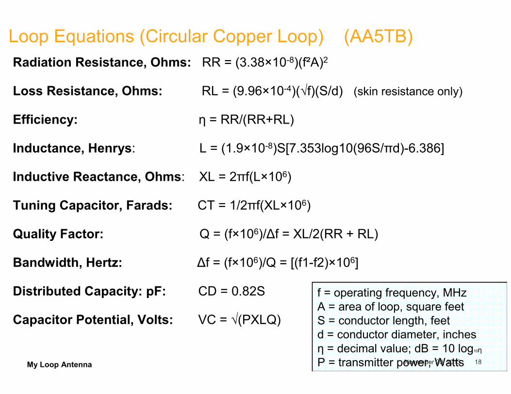
Loop Equations (Circular Copper Loop) (AA5TB)Radiation Resistance, Ohms: RR = (3.38×10⁻⁸)(f²A)2
Loss Resistance, Ohms: RL = (9.96×10⁻⁴)(√f)(S/d) (skin resistance only)
Efficiency: η = RR/(RR+RL)
Inductance, Henrys: L = (1.9×10⁻⁸)S[7.353log10(96S/πd)-6.386]
Inductive Reactance, Ohms: XL = 2πf(L×106)
Tuning Capacitor, Farads: CT = 1/2πf(XL×106)
Quality Factor: Q = (f×106)/∆f = XL/2(RR + RL)
Bandwidth, Hertz: ∆f = (f×106)/Q = [(f1-f2)×106]
Distributed Capacity: pF: CD = 0.82S
Capacitor Potential, Volts: VC = √(PXLQ)
f = operating frequency, MHzA = area of loop, square feetS = conductor length, feetd = conductor diameter, inchesη = decimal value; dB = 10 log10η
P = transmitter power, Watts
My Loop Antenna November 20, 2013 19
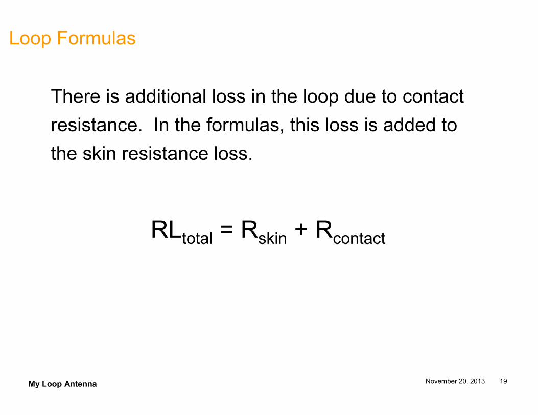
Loop Formulas
There is additional loss in the loop due to contact
resistance. In the formulas, this loss is added to
the skin resistance loss.
RLtotal = Rskin + Rcontact
My Loop Antenna November 20, 2013 20
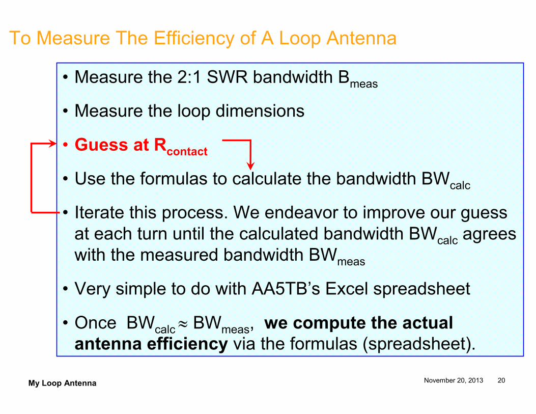
To Measure The Efficiency of A Loop Antenna
• Measure the 2:1 SWR bandwidth Bmeas
• Measure the loop dimensions
• Guess at Rcontact
• Use the formulas to calculate the bandwidth BWcalc
• Iterate this process. We endeavor to improve our guess at each turn until the calculated bandwidth BWcalc agrees with the measured bandwidth BWmeas
• Very simple to do with AA5TB’s Excel spreadsheet
• Once BWcalc ≈ BWmeas, we compute the actual
antenna efficiency via the formulas (spreadsheet).
My Loop Antenna November 20, 2013 21
To Measure The Efficiency of a Vertical Antenna
Phil Salas AD5DX shows how the efficiency of a vertical can be deduced from a knowledge of
the loading coil inductance and placement
the length of the antenna
the ground resistance
the 2:1 SWR bandwidth
http://www.ad5x.com/images/Presentations/Antenna%20Efficiency.pdf
We’ll evaluate the efficiency of our loop antenna and compare it to the
performance of various verticals
My Loop Antenna November 20, 2013 22
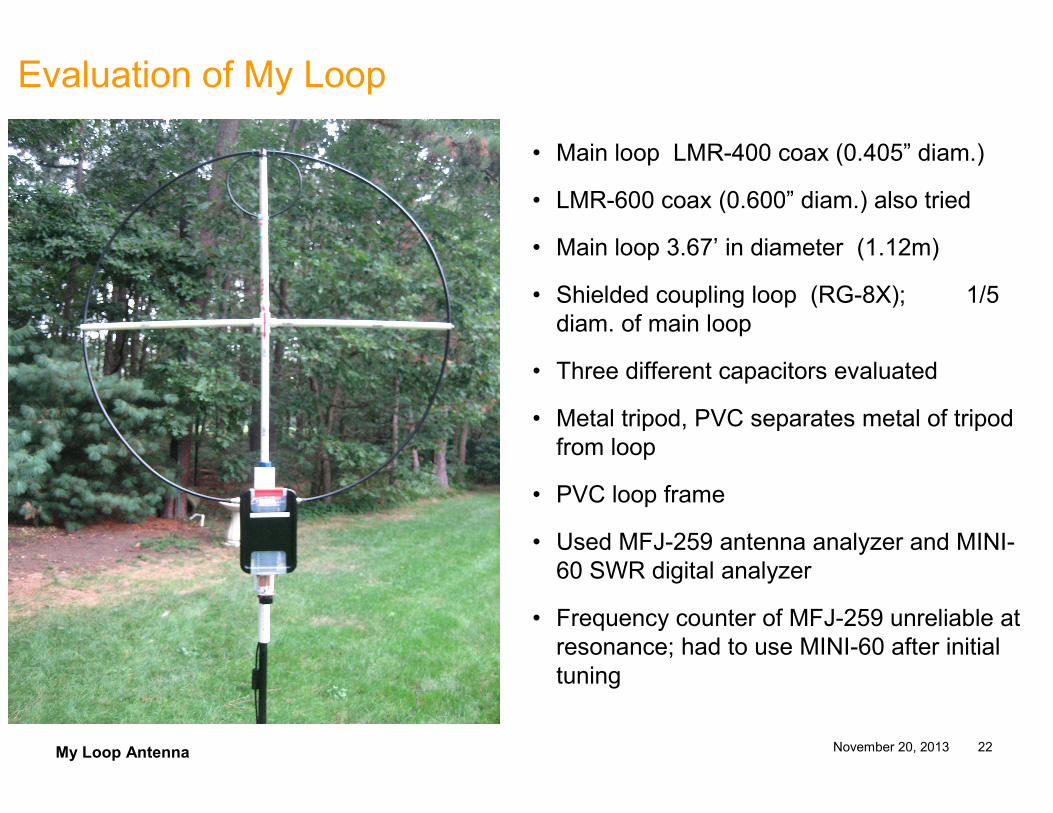
Evaluation of My Loop
• Main loop LMR-400 coax (0.405” diam.)
• LMR-600 coax (0.600” diam.) also tried
• Main loop 3.67’ in diameter (1.12m)
• Shielded coupling loop (RG-8X); 1/5 diam. of main loop
• Three different capacitors evaluated
• Metal tripod, PVC separates metal of tripod from loop
• PVC loop frame
• Used MFJ-259 antenna analyzer and MINI-60 SWR digital analyzer
• Frequency counter of MFJ-259 unreliable at resonance; had to use MINI-60 after initial tuning
My Loop Antenna November 20, 2013 23
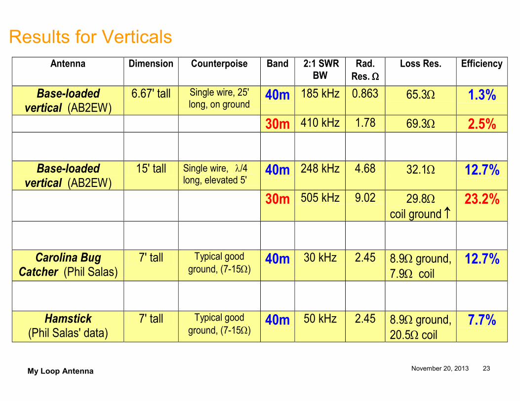
Results for Verticals
Antenna Dimension Counterpoise Band 2:1 SWR BW
Rad.
Res. ΩΩΩΩ
Loss Res. Efficiency
Base-loaded vertical (AB2EW)
6.67' tall Single wire, 25' long, on ground
40m 185 kHz 0.863 65.3Ω 1.3%
30m 410 kHz 1.78 69.3Ω 2.5%
Base-loaded vertical (AB2EW)
15' tall Single wire, λ/4 long, elevated 5'
40m 248 kHz 4.68 32.1Ω 12.7%
30m 505 kHz 9.02 29.8Ω coil ground ↑↑↑↑
23.2%
Carolina Bug Catcher (Phil Salas)
7' tall Typical good ground, (7-15Ω)
40m 30 kHz 2.45 8.9Ω ground, 7.9Ω coil
12.7%
Hamstick (Phil Salas' data)
7' tall Typical good ground, (7-15Ω)
40m 50 kHz 2.45 8.9Ω ground, 20.5Ω coil
7.7%
My Loop Antenna November 20, 2013 24
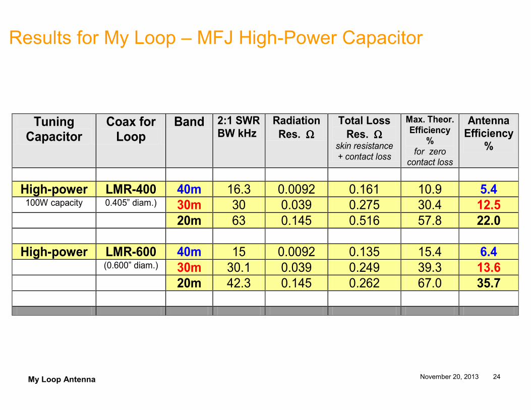
Results for My Loop – MFJ High-Power Capacitor
Tuning Capacitor
Coax for Loop
Band 2:1 SWR BW kHz
Radiation
Res. ΩΩΩΩ
Total Loss
Res. ΩΩΩΩ skin resistance + contact loss
Max. Theor. Efficiency
% for zero contact loss
Antenna Efficiency
%
High-power LMR-400 40m 16.3 0.0092 0.161 10.9 5.4 100W capacity 0.405” diam.) 30m 30 0.039 0.275 30.4 12.5
20m 63 0.145 0.516 57.8 22.0
High-power LMR-600 40m 15 0.0092 0.135 15.4 6.4
(0.600” diam.) 30m 30.1 0.039 0.249 39.3 13.6
20m 42.3 0.145 0.262 67.0 35.7
My Loop Antenna November 20, 2013 25
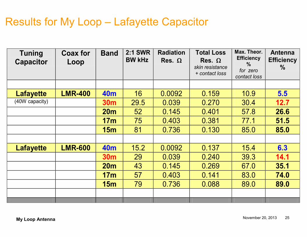
Results for My Loop – Lafayette Capacitor
Tuning Capacitor
Coax for Loop
Band 2:1 SWR BW kHz
Radiation
Res. ΩΩΩΩ
Total Loss
Res. ΩΩΩΩ skin resistance + contact loss
Max. Theor. Efficiency
% for zero contact loss
Antenna Efficiency
%
Lafayette LMR-400 40m 16 0.0092 0.159 10.9 5.5 (40W capacity) 30m 29.5 0.039 0.270 30.4 12.7
20m 52 0.145 0.401 57.8 26.6
17m 75 0.403 0.381 77.1 51.5
15m 81 0.736 0.130 85.0 85.0
Lafayette LMR-600 40m 15.2 0.0092 0.137 15.4 6.3
30m 29 0.039 0.240 39.3 14.1
20m 43 0.145 0.269 67.0 35.1
17m 57 0.403 0.141 83.0 74.0
15m 79 0.736 0.088 89.0 89.0
My Loop Antenna November 20, 2013 26
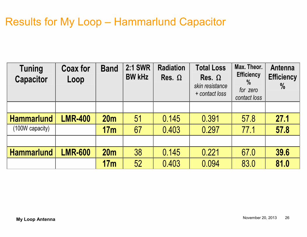
Results for My Loop – Hammarlund Capacitor
Tuning Capacitor
Coax for Loop
Band 2:1 SWR BW kHz
Radiation
Res. ΩΩΩΩ
Total Loss
Res. ΩΩΩΩ skin resistance + contact loss
Max. Theor. Efficiency
% for zero contact loss
Antenna Efficiency
%
Hammarlund LMR-400 20m 51 0.145 0.391 57.8 27.1 (100W capacity) 17m 67 0.403 0.297 77.1 57.8
Hammarlund LMR-600 20m 38 0.145 0.221 67.0 39.6
17m 52 0.403 0.094 83.0 81.0
My Loop Antenna November 20, 2013 27
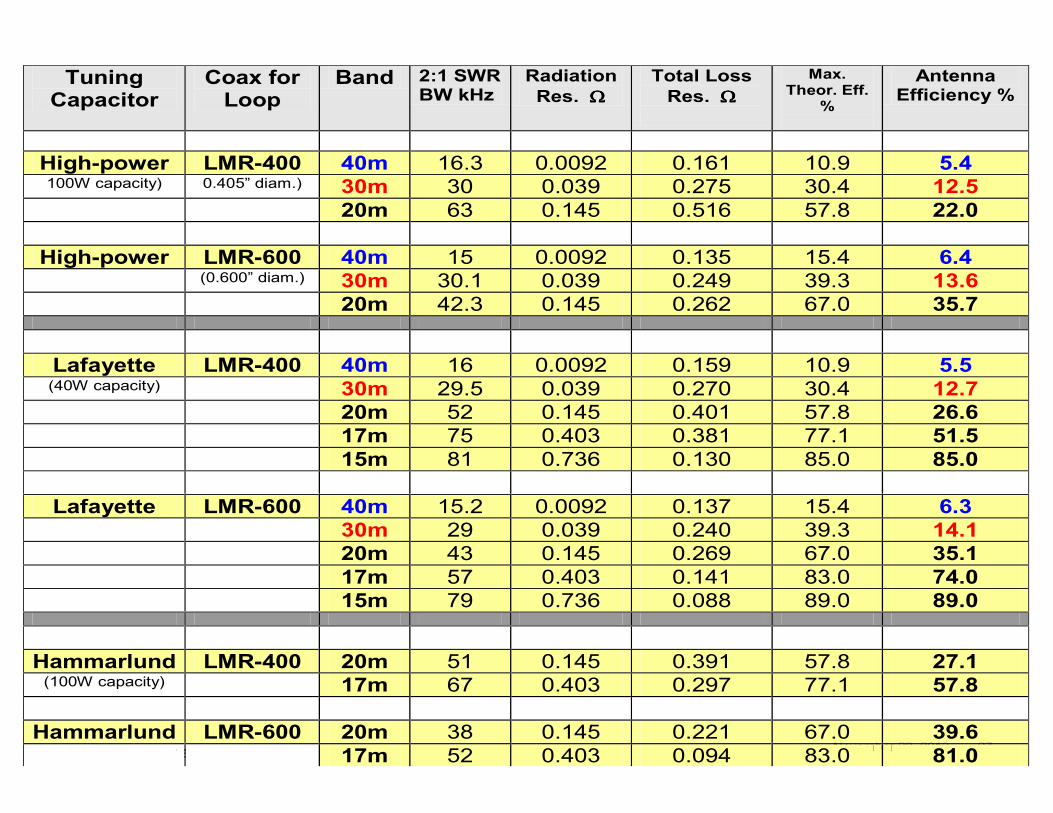
Tuning Capacitor
Coax for Loop
Band 2:1 SWR BW kHz
Radiation
Res. ΩΩΩΩ
Total Loss
Res. ΩΩΩΩ
Max. Theor. Eff.
%
Antenna Efficiency %
High-power LMR-400 40m 16.3 0.0092 0.161 10.9 5.4 100W capacity) 0.405” diam.) 30m 30 0.039 0.275 30.4 12.5
20m 63 0.145 0.516 57.8 22.0
High-power LMR-600 40m 15 0.0092 0.135 15.4 6.4
(0.600” diam.) 30m 30.1 0.039 0.249 39.3 13.6
20m 42.3 0.145 0.262 67.0 35.7
Lafayette LMR-400 40m 16 0.0092 0.159 10.9 5.5 (40W capacity) 30m 29.5 0.039 0.270 30.4 12.7
20m 52 0.145 0.401 57.8 26.6
17m 75 0.403 0.381 77.1 51.5
15m 81 0.736 0.130 85.0 85.0
Lafayette LMR-600 40m 15.2 0.0092 0.137 15.4 6.3
30m 29 0.039 0.240 39.3 14.1
20m 43 0.145 0.269 67.0 35.1
17m 57 0.403 0.141 83.0 74.0
15m 79 0.736 0.088 89.0 89.0
Hammarlund LMR-400 20m 51 0.145 0.391 57.8 27.1 (100W capacity) 17m 67 0.403 0.297 77.1 57.8
Hammarlund LMR-600 20m 38 0.145 0.221 67.0 39.6
17m 52 0.403 0.094 83.0 81.0
My Loop Antenna November 20, 2013 28
Summary and Conclusion
• Small portable loops provide excellent reception and good transmit efficiency in comparison to other portable antenna solutions
• Radials or counterpoises not required with loops
• Vertical loops work well at low elevations
• Bandwidth very narrow
• Very high voltages across tuning capacitor
• Very small radiation resistance requires great care in construction to avoid contact loss
My Loop Antenna November 20, 2013 29
DEMOS
• Voltage intensity around the loop
• AA5TB’s Excel Spreadsheet
My Loop Antenna November 20, 2013 30
References
Many of the figures were taken from the websites below. Certain references also provide in depth discussions of loop antennas (and vertical antennas from ref. 3)
1. http://www.aa5tb.com/loop.html
2. http://26hs4316.wordpress.com/antenna-construction/magnetic-loops/
3. http://www.ad5x.com/images/Presentations/Antenna%20Efficiency.pdf
4. http://www.ahars.com.au/documents/the_underestimated_magnetic_loop_hf_antenna_vers%201.1.pdf .
5. http://www.nonstopsystems.com/radio/frank_radio_antenna_magloop.htm .
6. alexloop.com ($366 for portable loop antenna)
7. amateurradiostore.com ($300 for portable loop antenna)