myhdl manual - read the docs · python’s power and clarity make myhdl an ideal solution for ......
TRANSCRIPT

MyHDL manualRelease 0.8
Jan Decaluwe
March 01, 2015


Contents
1 Overview 1
2 Background information 32.1 Prerequisites . . . . . . . . . . . . . . . . . . . . . . . . . . . . . . . . . . . . . . . 32.2 A small tutorial on generators . . . . . . . . . . . . . . . . . . . . . . . . . . . . . 32.3 About decorators . . . . . . . . . . . . . . . . . . . . . . . . . . . . . . . . . . . . . 4
3 Introduction to MyHDL 73.1 A basic MyHDL simulation . . . . . . . . . . . . . . . . . . . . . . . . . . . . . . . 73.2 Signals, ports, and concurrency . . . . . . . . . . . . . . . . . . . . . . . . . . . . . 83.3 Parameters and hierarchy . . . . . . . . . . . . . . . . . . . . . . . . . . . . . . . . 93.4 Some remarks on MyHDL and Python . . . . . . . . . . . . . . . . . . . . . . . . 113.5 Summary and perspective . . . . . . . . . . . . . . . . . . . . . . . . . . . . . . . . 12
4 Hardware-oriented types 134.1 The intbv class . . . . . . . . . . . . . . . . . . . . . . . . . . . . . . . . . . . . . 134.2 Bit indexing . . . . . . . . . . . . . . . . . . . . . . . . . . . . . . . . . . . . . . . . 154.3 Bit slicing . . . . . . . . . . . . . . . . . . . . . . . . . . . . . . . . . . . . . . . . . 164.4 The modbv class . . . . . . . . . . . . . . . . . . . . . . . . . . . . . . . . . . . . . 174.5 Unsigned and signed representation . . . . . . . . . . . . . . . . . . . . . . . . . . 18
5 Structural modeling 215.1 Introduction . . . . . . . . . . . . . . . . . . . . . . . . . . . . . . . . . . . . . . . . 215.2 Conditional instantiation . . . . . . . . . . . . . . . . . . . . . . . . . . . . . . . . 215.3 Converting between lists of signals and bit vectors . . . . . . . . . . . . . . . . . 225.4 Inferring the list of instances . . . . . . . . . . . . . . . . . . . . . . . . . . . . . . 23
6 RTL modeling 256.1 Introduction . . . . . . . . . . . . . . . . . . . . . . . . . . . . . . . . . . . . . . . . 256.2 Combinatorial logic . . . . . . . . . . . . . . . . . . . . . . . . . . . . . . . . . . . 256.3 Sequential logic . . . . . . . . . . . . . . . . . . . . . . . . . . . . . . . . . . . . . . 276.4 Finite State Machine modeling . . . . . . . . . . . . . . . . . . . . . . . . . . . . . 29
7 High level modeling 337.1 Introduction . . . . . . . . . . . . . . . . . . . . . . . . . . . . . . . . . . . . . . . . 337.2 Modeling with bus-functional procedures . . . . . . . . . . . . . . . . . . . . . . 337.3 Modeling memories with built-in types . . . . . . . . . . . . . . . . . . . . . . . . 387.4 Modeling errors using exceptions . . . . . . . . . . . . . . . . . . . . . . . . . . . 39
i

7.5 Object oriented modeling . . . . . . . . . . . . . . . . . . . . . . . . . . . . . . . . 41
8 Unit testing 438.1 Introduction . . . . . . . . . . . . . . . . . . . . . . . . . . . . . . . . . . . . . . . . 438.2 The importance of unit tests . . . . . . . . . . . . . . . . . . . . . . . . . . . . . . . 438.3 Unit test development . . . . . . . . . . . . . . . . . . . . . . . . . . . . . . . . . . 44
9 Co-simulation with Verilog 499.1 Introduction . . . . . . . . . . . . . . . . . . . . . . . . . . . . . . . . . . . . . . . . 499.2 The HDL side . . . . . . . . . . . . . . . . . . . . . . . . . . . . . . . . . . . . . . . 499.3 The MyHDL side . . . . . . . . . . . . . . . . . . . . . . . . . . . . . . . . . . . . . 509.4 Restrictions . . . . . . . . . . . . . . . . . . . . . . . . . . . . . . . . . . . . . . . . 529.5 Implementation notes . . . . . . . . . . . . . . . . . . . . . . . . . . . . . . . . . . 53
10 Conversion to Verilog and VHDL 5710.1 Introduction . . . . . . . . . . . . . . . . . . . . . . . . . . . . . . . . . . . . . . . . 5710.2 Solution description . . . . . . . . . . . . . . . . . . . . . . . . . . . . . . . . . . . 5710.3 Features . . . . . . . . . . . . . . . . . . . . . . . . . . . . . . . . . . . . . . . . . . 5710.4 The convertible subset . . . . . . . . . . . . . . . . . . . . . . . . . . . . . . . . . . 5910.5 Conversion of lists of signals . . . . . . . . . . . . . . . . . . . . . . . . . . . . . . 6210.6 Conversion of Interfaces . . . . . . . . . . . . . . . . . . . . . . . . . . . . . . . . . 6210.7 Assignment issues . . . . . . . . . . . . . . . . . . . . . . . . . . . . . . . . . . . . 6310.8 Excluding code from conversion . . . . . . . . . . . . . . . . . . . . . . . . . . . . 6410.9 User-defined code . . . . . . . . . . . . . . . . . . . . . . . . . . . . . . . . . . . . 6410.10 Template transformation . . . . . . . . . . . . . . . . . . . . . . . . . . . . . . . . 6510.11 Conversion output verification by co-simulation . . . . . . . . . . . . . . . . . . . 6610.12 Conversion of test benches . . . . . . . . . . . . . . . . . . . . . . . . . . . . . . . 6610.13 Methodology notes . . . . . . . . . . . . . . . . . . . . . . . . . . . . . . . . . . . . 6710.14 Known issues . . . . . . . . . . . . . . . . . . . . . . . . . . . . . . . . . . . . . . . 67
11 Conversion examples 6911.1 Introduction . . . . . . . . . . . . . . . . . . . . . . . . . . . . . . . . . . . . . . . . 6911.2 A small sequential design . . . . . . . . . . . . . . . . . . . . . . . . . . . . . . . . 6911.3 A small combinatorial design . . . . . . . . . . . . . . . . . . . . . . . . . . . . . . 7111.4 A hierarchical design . . . . . . . . . . . . . . . . . . . . . . . . . . . . . . . . . . . 7311.5 Optimizations for finite state machines . . . . . . . . . . . . . . . . . . . . . . . . 7511.6 RAM inference . . . . . . . . . . . . . . . . . . . . . . . . . . . . . . . . . . . . . . 7911.7 ROM inference . . . . . . . . . . . . . . . . . . . . . . . . . . . . . . . . . . . . . . 8111.8 User-defined code . . . . . . . . . . . . . . . . . . . . . . . . . . . . . . . . . . . . 82
12 Reference 8512.1 Simulation . . . . . . . . . . . . . . . . . . . . . . . . . . . . . . . . . . . . . . . . . 8512.2 Modeling . . . . . . . . . . . . . . . . . . . . . . . . . . . . . . . . . . . . . . . . . 8612.3 Co-simulation . . . . . . . . . . . . . . . . . . . . . . . . . . . . . . . . . . . . . . . 9312.4 Conversion to Verilog and VHDL . . . . . . . . . . . . . . . . . . . . . . . . . . . 9412.5 Conversion output verification . . . . . . . . . . . . . . . . . . . . . . . . . . . . . 95
Python Module Index 97
ii

CHAPTER 1
Overview
The goal of the MyHDL project is to empower hardware designers with the elegance andsimplicity of the Python language.
MyHDL is a free, open-source package for using Python as a hardware description and ver-ification language. Python is a very high level language, and hardware designers can use itsfull power to model and simulate their designs. Moreover, MyHDL can convert a design toVerilog or VHDL. This provides a path into a traditional design flow.
Modeling
Python’s power and clarity make MyHDL an ideal solution for high level modeling. Pythonis famous for enabling elegant solutions to complex modeling problems. Moreover, Python isoutstanding for rapid application development and experimentation.
The key idea behind MyHDL is the use of Python generators to model hardware concurrency.Generators are best described as resumable functions. MyHDL generators are similar to al-ways blocks in Verilog and processes in VHDL.
A hardware module is modeled as a function that returns generators. This approach makesit straightforward to support features such as arbitrary hierarchy, named port association, ar-rays of instances, and conditional instantiation. Furthermore, MyHDL provides classes thatimplement traditional hardware description concepts. It provides a signal class to supportcommunication between generators, a class to support bit oriented operations, and a class forenumeration types.
Simulation and Verification
The built-in simulator runs on top of the Python interpreter. It supports waveform viewing bytracing signal changes in a VCD file.
With MyHDL, the Python unit test framework can be used on hardware designs. Althoughunit testing is a popular modern software verification technique, it is still uncommon in thehardware design world.
MyHDL can also be used as hardware verification language for Verilog designs, by co-simulation with traditional HDL simulators.
Conversion to Verilog and VHDL
Subject to some limitations, MyHDL designs can be converted to Verilog or VHDL. This pro-vides a path into a traditional design flow, including synthesis and implementation. The con-vertible subset is restricted, but much wider than the standard synthesis subset. It includesfeatures that can be used for high level modeling and test benches.
1

MyHDL manual, Release 0.8
The converter works on an instantiated design that has been fully elaborated. Consequently,the original design structure can be arbitrarily complex. Moreover, the conversion limitationsapply only to code inside generators. Outside generators, Python’s full power can be usedwithout compromising convertibility.
Finally, the converter automates a number of tasks that are hard in Verilog or VHDL directly.A notable feature is the automated handling of signed arithmetic issues.
2 Chapter 1. Overview

CHAPTER 2
Background information
2.1 Prerequisites
You need a basic understanding of Python to use MyHDL. If you don’t know Python, don’tworry: it is is one of the easiest programming languages to learn 1. Learning Python is one ofthe best time investments that engineering professionals can make 2.
For starters, http://docs.python.org/tutorial is probably the best choice for an on-line tutorial.For alternatives, see http://wiki.python.org/moin/BeginnersGuide.
A working knowledge of a hardware description language such as Verilog or VHDL is helpful.
Code examples in this manual are sometimes shortened for clarity. Complete executable ex-amples can be found in the distribution directory at example/manual/.
2.2 A small tutorial on generators
Generators were introduced in Python 2.2. Because generators are the key concept in MyHDL,a small tutorial is included here.
Consider the following nonsensical function:
def function():for i in range(5):
return i
You can see why it doesn’t make a lot of sense. As soon as the first loop iteration is entered,the function returns:
>>> function()0
Returning is fatal for the function call. Further loop iterations never get a chance, and nothingis left over from the function call when it returns.
To change the function into a generator function, we replace return with yield:
def generator():for i in range(5):
yield i
1 You must be bored by such claims, but in Python’s case it’s true.2 I am not biased.
3

MyHDL manual, Release 0.8
Now we get:
>>> generator()<generator object at 0x815d5a8>
When a generator function is called, it returns a generator object. A generator object supportsthe iterator protocol, which is an expensive way of saying that you can let it generate subse-quent values by calling its next() method:
>>> g = generator()>>> g.next()0>>> g.next()1>>> g.next()2>>> g.next()3>>> g.next()4>>> g.next()Traceback (most recent call last):
File "<stdin>", line 1, in ?StopIteration
Now we can generate the subsequent values from the for loop on demand, until they areexhausted. What happens is that the yield statement is like a return, except that it is non-fatal: the generator remembers its state and the point in the code when it yielded. A higherorder agent can decide when to get the next value by calling the generator’s next() method.We say that generators are resumable functions.
If you are familiar with hardware description languages, this may ring a bell. In hardwaresimulations, there is also a higher order agent, the Simulator, that interacts with such resum-able functions; they are called processes in VHDL and always blocks in Verilog. Similarly, Pythongenerators provide an elegant and efficient method to model concurrency, without having toresort to some form of threading.
The use of generators to model concurrency is the first key concept in MyHDL. The secondkey concept is a related one: in MyHDL, the yielded values are used to specify the conditionson which the generator should wait before resuming. In other words, yield statements workas general sensitivity lists.
2.3 About decorators
Python 2.4 introduced a feature called decorators. MyHDL takes advantage of this feature bydefining a number of decorators that facilitate hardware descriptions. However, some usersmay not yet be familiar with decorators. Therefore, an introduction is included here.
A decorator consists of special syntax in front of a function declaration. It refers to a decoratorfunction. The decorator function automatically transforms the declared function into someother callable object.
A decorator function deco() is used in a decorator statement as follows:
4 Chapter 2. Background information

MyHDL manual, Release 0.8
@decodef func(arg1, arg2, ...):
<body>
This code is equivalent to the following:
def func(arg1, arg2, ...):<body>
func = deco(func)
Note that the decorator statement goes directly in front of the function declaration, and thatthe function name func() is automatically reused for the final result.
MyHDL uses decorators to create ready-to-simulate generators from local function definitions.Their functionality and usage will be described extensively in this manual.
2.3. About decorators 5

MyHDL manual, Release 0.8
6 Chapter 2. Background information

CHAPTER 3
Introduction to MyHDL
3.1 A basic MyHDL simulation
We will introduce MyHDL with a classic Hello World style example. All example code canbe found in the distribution directory under example/manual/. Here are the contents of aMyHDL simulation script called hello1.py:
from myhdl import Signal, delay, always, now, Simulation
def HelloWorld():
interval = delay(10)
@always(interval)def sayHello():
print "%s Hello World!" % now()
return sayHello
inst = HelloWorld()sim = Simulation(inst)sim.run(30)
When we run this simulation, we get the following output:
% python hello1.py10 Hello World!20 Hello World!30 Hello World!_SuspendSimulation: Simulated 30 timesteps
The first line of the script imports a number of objects from the myhdl package. In Python wecan only use identifiers that are literally defined in the source file 1.
Then, we define a function called HelloWorld(). In MyHDL, hardware modules can bemodeled using classic functions. In particular, the parameter list is then used to define theinterface. In this first example, the interface is empty.
1 The exception is the from module import * syntax, that imports all the symbols from a module. Althoughthis is generally considered bad practice, it can be tolerated for large modules that export a lot of symbols. Onemay argue that myhdl falls into that category.
7
MyHDL manual, Release 0.8
Inside the top level function we declare a local function called sayHello() that defines thedesired behavior. This function is decorated with an always() decorator that has a delay ob-ject as its parameter. The meaning is that the function will be executed whenever the specifieddelay interval has expired.
Behind the curtains, the always() decorator creates a Python generator and reuses the nameof the decorated function for it. Generators are the fundamental objects in MyHDL, and wewill say much more about them further on.
Finally, the top level function returns the local generator. This is the simplest case of the ba-sic MyHDL code pattern to define the contents of a hardware module. We will describe thegeneral case further on.
In MyHDL, we create an instance of a hardware module by calling the corresponding func-tion. In the example, variable inst refers to an instance of HelloWorld(). To simulate theinstance, we pass it as an argument to a Simulation object constructor. We then run thesimulation for the desired amount of timesteps.
3.2 Signals, ports, and concurrency
In the previous section, we simulated a design with a single generator and no concurrency.Real hardware descriptions are typically massively concurrent. MyHDL supports this by al-lowing an arbitrary number of concurrently running generators.
With concurrency comes the problem of deterministic communication. Hardware languagesuse special objects to support deterministic communication between concurrent code. In par-ticular, MyHDL has a Signal object which is roughly modeled after VHDL signals.
We will demonstrate signals and concurrency by extending and modifying our first example.We define two hardware modules, one that drives a clock signal, and one that is sensitive to apositive edge on a clock signal:
from myhdl import Signal, delay, always, now, Simulation
def ClkDriver(clk):
halfPeriod = delay(10)
@always(halfPeriod)def driveClk():
clk.next = not clk
return driveClk
def HelloWorld(clk):
@always(clk.posedge)def sayHello():
print "%s Hello World!" % now()
return sayHello
8 Chapter 3. Introduction to MyHDL

MyHDL manual, Release 0.8
clk = Signal(0)clkdriver_inst = ClkDriver(clk)hello_inst = HelloWorld(clk)sim = Simulation(clkdriver_inst, hello_inst)sim.run(50)
The clock driver function ClkDriver() has a clock signal as its parameter. This is how a portis modeled in MyHDL. The function defines a generator that continuously toggles a clock sig-nal after a certain delay. A new value of a signal is specified by assigning to its next attribute.This is the MyHDL equivalent of the VHDL signal assignment and the Verilog non-blockingassignment.
The HelloWorld() function is modified from the first example. It now also takes a clocksignal as parameter. Its generator is made sensitive to a rising edge of the clock signal. Thisis specified by the posedge attribute of a signal. The edge specifier is the argument of thealways decorator. As a result, the decorated function will be executed on every rising clockedge.
The clk signal is constructed with an initial value 0. When creating an instance of each hard-ware module, the same clock signal is passed as the argument. The result is that the instancesare now connected through the clock signal. The Simulation object is constructed with thetwo instances.
When we run the simulation, we get:
% python hello2.py10 Hello World!30 Hello World!50 Hello World!_SuspendSimulation: Simulated 50 timesteps
3.3 Parameters and hierarchy
We have seen that MyHDL uses functions to model hardware modules. We have also seen thatports are modeled by using signals as parameters. To make designs reusable we will also wantto use other objects as parameters. For example, we can change the clock generator function tomake it more general and reusable, by making the clock period parametrizable, as follows:
from myhdl import Signal, delay, instance, always, now, Simulation
def ClkDriver(clk, period=20):
lowTime = int(period/2)highTime = period - lowTime
@instancedef driveClk():
while True:yield delay(lowTime)clk.next = 1yield delay(highTime)clk.next = 0
return driveClk
3.3. Parameters and hierarchy 9

MyHDL manual, Release 0.8
In addition to the clock signal, the clock period is a parameter, with a default value of 20.
As the low time of the clock may differ from the high time in case of an odd period, we cannotuse the always() decorator with a single delay value anymore. Instead, the driveClk()function is now a generator function with an explicit definition of the desired behavior. Itis decorated with the instance() decorator. You can see that driveClk() is a generatorfunction because it contains yield statements.
When a generator function is called, it returns a generator object. This is basically what theinstance() decorator does. It is less sophisticated than the always() decorator, but it canbe used to create a generator from any local generator function.
The yield statement is a general Python construct, but MyHDL uses it in a dedicated way.In MyHDL, it has a similar meaning as the wait statement in VHDL: the statement suspendsexecution of a generator, and its clauses specify the conditions on which the generator shouldwait before resuming. In this case, the generator waits for a certain delay.
Note that to make sure that the generator runs “forever”, we wrap its behavior in a whileTrue loop.
Similarly, we can define a general Hello() function as follows:
def Hello(clk, to="World!"):
@always(clk.posedge)def sayHello():
print "%s Hello %s" % (now(), to)
return sayHello
We can create any number of instances by calling the functions with the appropriate param-eters. Hierarchy can be modeled by defining the instances in a higher-level function, andreturning them. This pattern can be repeated for an arbitrary number of hierarchical levels.Consequently, the general definition of a MyHDL instance is recursive: an instance is either asequence of instances, or a generator.
As an example, we will create a higher-level function with four instances of the lower-levelfunctions, and simulate it:
def greetings():
clk1 = Signal(0)clk2 = Signal(0)
clkdriver_1 = ClkDriver(clk1) # positional and default associationclkdriver_2 = ClkDriver(clk=clk2, period=19) # named associationhello_1 = Hello(clk=clk1) # named and default associationhello_2 = Hello(to="MyHDL", clk=clk2) # named association
return clkdriver_1, clkdriver_2, hello_1, hello_2
inst = greetings()sim = Simulation(inst)sim.run(50)
As in standard Python, positional or named parameter association can be used in instantia-
10 Chapter 3. Introduction to MyHDL

MyHDL manual, Release 0.8
tions, or a mix of both 2. All these styles are demonstrated in the example above. Namedassociation can be very useful if there are a lot of parameters, as the argument order in the calldoes not matter in that case.
The simulation produces the following output:
% python greetings.py9 Hello MyHDL10 Hello World!28 Hello MyHDL30 Hello World!47 Hello MyHDL50 Hello World!_SuspendSimulation: Simulated 50 timesteps
Warning: Some commonly used terminology has different meanings in Python versushardware design. Rather than artificially changing terminology, I think it’s best to keep itand explicitly describing the differences.A module in Python refers to all source code in a particular file. A module can be reused byother modules by importing. In hardware design, a module is a reusable block of hardwarewith a well defined interface. It can be reused in another module by instantiating it.An instance in Python (and other object-oriented languages) refers to the object created by aclass constructor. In hardware design, an instance is a particular incarnation of a hardwaremodule.Normally, the meaning should be clear from the context. Occasionally, I may qualify termswith the words “hardware” or “MyHDL” to avoid ambiguity.
3.4 Some remarks on MyHDL and Python
To conclude this introductory chapter, it is useful to stress that MyHDL is not a language initself. The underlying language is Python, and MyHDL is implemented as a Python packagecalled myhdl. Moreover, it is a design goal to keep the myhdl package as minimalistic aspossible, so that MyHDL descriptions are very much “pure Python”.
To have Python as the underlying language is significant in several ways:
• Python is a very powerful high level language. This translates into high productivity andelegant solutions to complex problems.
• Python is continuously improved by some very clever minds, supported by a large andfast growing user base. Python profits fully from the open source development model.
• Python comes with an extensive standard library. Some functionality is likely to be ofdirect interest to MyHDL users: examples include string handling, regular expressions,random number generation, unit test support, operating system interfacing and GUIdevelopment. In addition, there are modules for mathematics, database connections,networking programming, internet data handling, and so on.
• Python has a powerful C extension model. All built-in types are written with the sameC API that is available for custom extensions. To a module user, there is no differencebetween a standard Python module and a C extension module — except performance.The typical Python development model is to prototype everything in Python until the
2 All positional parameters have to go before any named parameter.
3.4. Some remarks on MyHDL and Python 11

MyHDL manual, Release 0.8
application is stable, and (only) then rewrite performance critical modules in C if neces-sary.
3.5 Summary and perspective
Here is an overview of what we have learned in this chapter:
• Generators are the basic building blocks of MyHDL models. They provide the way tomodel massive concurrency and sensitivity lists.
• MyHDL provides decorators that create useful generators from local functions.
• Hardware structure and hierarchy is described with classic Python functions.
• Signal objects are used to communicate between concurrent generators.
• A Simulation object is used to simulate MyHDL models.
These concepts are sufficient to start modeling and simulating with MyHDL.
However, there is much more to MyHDL. Here is an overview of what can be learned from thefollowing chapters:
• MyHDL supports hardware-oriented types that make it easier to write typical hardwaremodels. These are described in Chapter Hardware-oriented types.
• MyHDL supports sophisticated and high level modeling techniques. This is described inChapter High level modeling.
• MyHDL enables the use of modern software verification techniques, such as unit testing,on hardware designs. This is the topic of Chapter Unit testing.
• It is possible to co-simulate MyHDL models with other HDL languages such as Verilogand VHDL. This is described in Chapter Co-simulation with Verilog.
• Last but not least, MyHDL models can be converted to Verilog, providing a path to asilicon implementation. This is the topic of Chapter Conversion to Verilog and VHDL.
12 Chapter 3. Introduction to MyHDL

CHAPTER 4
Hardware-oriented types
4.1 The intbv class
Hardware design involves dealing with bits and bit-oriented operations. The standard Pythontype int has most of the desired features, but lacks support for indexing and slicing. For thisreason, MyHDL provides the intbv class. The name was chosen to suggest an integer withbit vector flavor.
intbv works transparently with other integer-like types. Like class int, it provides access tothe underlying two’s complement representation for bitwise operations. However, unlike int,it is a mutable type. This means that its value can be changed after object creation, throughmethods and operators such as slice assignment.
intbv supports the same operators as int for arithmetic. In addition, it provides a numberof features to make it suitable for hardware design. First, the range of allowed values can beconstrained. This makes it possible to check the value at run time during simulation. More-over, back end tools can determine the smallest possible bit width for representing the object.Secondly, it supports bit level operations by providing an indexing and slicing interface.
intbv objects are constructed in general as follows:
intbv([val=None] [, min=None] [, max=None])
val is the initial value. min and max can be used to constrain the value. Following the Pythonconventions, min is inclusive, and max is exclusive. Therefore, the allowed value range is min.. max-1.
Let’s us look at some examples. First, an unconstrained intbv object is created as follows:
>>> a = intbv(24)
After object creation, min and max are available as attributes for inspection. Also, the standardPython function len() can be used to determine the bit width. If we inspect the previouslycreated object, we get:
>>> print a.minNone>>> print a.maxNone>>> print len(a)0
13

MyHDL manual, Release 0.8
As the instantiation was unconstrained, the min and max attributes are undefined. Likewise,the bit width is undefined, which is indicated by a return value 0.
A constrained intbv object is created as follows:
>>> a = intbv(24, min=0, max=25)
Inspecting the object now gives:
>>> a.min0>>> a.max25>>> len(a)5
We see that the allowed value range is 0 .. 24, and that 5 bits are required to represent theobject.
Sometimes hardware engineers prefer to constrain an object by defining its bit width directly,instead of the range of allowed values. The following example shows how to do that:
>>> a = intbv(24)[5:]
What actually happens here is that first an unconstrained intbv is created, which is thensliced. Slicing an intbv returns a new intbv with the constraints set up appropriately. In-specting the object now shows:
>>> a.min0>>> a.max32>>> len(a)5
Note that the max attribute is 32, as with 5 bits it is possible to represent the range 0 .. 31. Cre-ating an intbv this way has the disadvantage that only positive value ranges can be specified.Slicing is described in more detail in Bit slicing.
To summarize, there are two ways to constrain an intbv object: by defining its bit width,or by defining its value range. The bit width method is more traditional in hardware design.However, there are two reasons to use the range method instead: to represent negative valuesas observed above, and for fine-grained control over the value range.
Fine-grained control over the value range permits better error checking, as there is no needfor the min and max bounds to be symmetric or powers of 2. In all cases, the bit width is setappropriately to represent all values in the range. For example:
>>> a = intbv(6, min=0, max=7)>>> len(a)3>>> a = intbv(6, min=-3, max=7)>>> len(a)4>>> a = intbv(6, min=-13, max=7)>>> len(a)5
14 Chapter 4. Hardware-oriented types

MyHDL manual, Release 0.8
4.2 Bit indexing
As an example, we will consider the design of a Gray encoder. The following code is a Grayencoder modeled in MyHDL:
from myhdl import Signal, delay, Simulation, always_comb, instance, intbv, bin
def bin2gray(B, G, width):""" Gray encoder.
B -- input intbv signal, binary encodedG -- output intbv signal, gray encodedwidth -- bit width"""
@always_combdef logic():
for i in range(width):G.next[i] = B[i+1] ^ B[i]
return logic
This code introduces a few new concepts. The string in triple quotes at the start of the functionis a doc string. This is standard Python practice for structured documentation of code.
Furthermore, we introduce a third decorator: always_comb(). It is used with a classic func-tion and specifies that the resulting generator should wait for a value change on any inputsignal. This is typically used to describe combinatorial logic. The always_comb() decoratorautomatically infers which signals are used as inputs.
Finally, the code contains bit indexing operations and an exclusive-or operator as required fora Gray encoder. By convention, the lsb of an intbv object has index 0.
To verify the Gray encoder, we write a test bench that prints input and output for all possibleinput values:
def testBench(width):
B = Signal(intbv(0))G = Signal(intbv(0))
dut = bin2gray(B, G, width)
@instancedef stimulus():
for i in range(2**width):B.next = intbv(i)yield delay(10)print "B: " + bin(B, width) + "| G: " + bin(G, width)
return dut, stimulus
We use the conversion function bin() to get a binary string representation of the signal values.This function is exported by the myhdl package and supplements the standard Python hex()and oct() conversion functions.
As a demonstration, we set up a simulation for a small width:
4.2. Bit indexing 15

MyHDL manual, Release 0.8
sim = Simulation(testBench(width=3))sim.run()
The simulation produces the following output:
% python bin2gray.pyB: 000 | G: 000B: 001 | G: 001B: 010 | G: 011B: 011 | G: 010B: 100 | G: 110B: 101 | G: 111B: 110 | G: 101B: 111 | G: 100StopSimulation: No more events
4.3 Bit slicing
For a change, we will use a traditional function as an example to illustrate slicing. The follow-ing function calculates the HEC byte of an ATM header.
from myhdl import intbv, concat
COSET = 0x55
def calculateHec(header):""" Return hec for an ATM header, represented as an intbv.
The hec polynomial is 1 + x + x**2 + x**8."""hec = intbv(0)for bit in header[32:]:
hec[8:] = concat(hec[7:2],bit ^ hec[1] ^ hec[7],bit ^ hec[0] ^ hec[7],bit ^ hec[7]
)return hec ^ COSET
The code shows how slicing access and assignment is supported on the intbv data type. Inaccordance with the most common hardware convention, and unlike standard Python, slicingranges are downward. The code also demonstrates concatenation of intbv objects.
As in standard Python, the slicing range is half-open: the highest index bit is not included.Unlike standard Python however, this index corresponds to the leftmost item. Both indices canbe omitted from the slice. If the leftmost index is omitted, the meaning is to access “all” higherorder bits. If the rightmost index is omitted, it is 0 by default.
The half-openness of a slice may seem awkward at first, but it helps to avoid one-off countissues in practice. For example, the slice hex[8:] has exactly 8 bits. Likewise, the slicehex[7:2] has 7-2=5 bits. You can think about it as follows: for a slice [i:j], only bitsbelow index i are included, and the bit with index j is the last bit included.
When an intbv object is sliced, a new intbv object is returned. This new intbv object isalways positive, and the value bounds are set up in accordance with the bit width specified by
16 Chapter 4. Hardware-oriented types

MyHDL manual, Release 0.8
the slice. For example:
>>> a = intbv(6, min=-3, max=7)>>> len(a)4>>> b = a[4:]>>> bintbv(6L)>>> len(b)4>>> b.min0>>> b.max16
In the example, the original object is sliced with a slice equal to its bit width. The returnedobject has the same value and bit width, but its value range consists of all positive values thatcan be represented by the bit width.
The object returned by a slice is positive, even when the original object is negative:
>>> a = intbv(-3)>>> bin(a, width=5)’11101’>>> b = a[5:]>>> bintbv(29L)>>> bin(b)’11101’
The bit pattern of the two objects is identical within the bit width, but their values have oppo-site sign.
4.4 The modbv class
In hardware modeling, there is often a need for the elegant modeling of wrap-around behavior.intbv instances do not support this automatically, as they assert that any assigned value iswithin the bound constraints. However, wrap-around modeling can be straightforward. Forexample, the wrap-around condition for a counter is often decoded explicitly, as it is needed forother purposes. Also, the modulo operator provides an elegant one-liner in many scenarios:
count.next = (count + 1) % 2**8
However, some interesting cases are not supported by the intbv type. For example, we wouldlike to describe a free running counter using a variable and augmented assignment as follows:
count_var += 1
This is not possible with the intbv type, as we cannot add the modulo behavior to this de-scription. A similar problem exist for an augmented left shift as follows:
shifter <<= 4
To support these operations directly, MyHDL provides the modbv type. modbv is implementedas a subclass of intbv. The two classes have an identical interface and work together in astraightforward way for arithmetic operations. The only difference is how the bounds are
4.4. The modbv class 17

MyHDL manual, Release 0.8
handled: out-of-bound values result in an error with intbv, and in wrap-around with modbv.For example, the modulo counter above can be modeled as follows:
count = Signal(modbv(0, min=0, max=2**8))...count.next = count + 1
The wrap-around behavior is defined in general as follows:
val = (val - min) % (max - min) + min
In a typical case when min==0, this reduces to:
val = val % max
4.5 Unsigned and signed representation
intbv is designed to be as high level as possible. The underlying value of an intbv object is aPython int, which is represented as a two’s complement number with “indefinite” bit width.The range bounds are only used for error checking, and to calculate the minimum required bitwidth for representation. As a result, arithmetic can be performed like with normal integers.
In contrast, HDLs such as Verilog and VHDL typically require designers to deal with represen-tational issues, especially for synthesizable code. They provide low-level types like signedand unsigned for arithmetic. The rules for arithmetic with such types are much more com-plicated than with plain integers.
In some cases it can be useful to interpret intbv objects in terms of “signed” and “unsigned”.Basically, it depends on attribute min. if min < 0, then the object is “signed”, otherwise it is“unsigned”. In particular, the bit width of a “signed” object will account for a sign bit, but thatof an “unsigned” will not, because that would be redundant. From earlier sections, we havelearned that the return value from a slicing operation is always “unsigned”.
In some applications, it is desirable to convert an “unsigned” intbv to a “signed”, in otherwords, to interpret the msb bit as a sign bit. The msb bit is the highest order bit within theobject’s bit width. For this purpose, intbv provides the intbv.signed() method. Forexample:
>>> a = intbv(12, min=0, max=16)>>> bin(a)’1100’>>> b = a.signed()>>> b-4>>> bin(b, width=4)’1100’
intbv.signed() extends the msb bit into the higher-order bits of the underlying objectvalue, and returns the result as an integer. Naturally, for a “signed” the return value willalways be identical to the original value, as it has the sign bit already.
As an example let’s take a 8 bit wide data bus that would be modeled as follows:
data_bus = intbv(0)[8:]
18 Chapter 4. Hardware-oriented types

MyHDL manual, Release 0.8
Now consider that a complex number is transferred over this data bus. The upper 4 bits ofthe data bus are used for the real value and the lower 4 bits for the imaginary value. As realand imaginary values have a positive and negative value range, we can slice them off from thedata bus and convert them as follows:
real.next = data_bus[8:4].signed()imag.next = data_bus[4:].signed()
4.5. Unsigned and signed representation 19
MyHDL manual, Release 0.8
20 Chapter 4. Hardware-oriented types

CHAPTER 5
Structural modeling
5.1 Introduction
Hardware descriptions need to support the concepts of module instantiation and hierarchy.In MyHDL, an instance is recursively defined as being either a sequence of instances, or agenerator. Hierarchy is modeled by defining instances in a higher-level function, and returningthem. The following is a schematic example of the basic case.
def top(...):...instance_1 = module_1(...)instance_2 = module_2(...)...instance_n = module_n(...)...return instance_1, instance_2, ... , instance_n
Note that MyHDL uses conventional procedural techniques for modeling structure. Thismakes it straightforward to model more complex cases.
5.2 Conditional instantiation
To model conditional instantiation, we can select the returned instance under parameter con-trol. For example:
SLOW, MEDIUM, FAST = range(3)
def top(..., speed=SLOW):...def slowAndSmall():
......def fastAndLarge():
...if speed == SLOW:
return slowAndSmall()elif speed == FAST:
return fastAndLarge()else:
raise NotImplementedError
21
MyHDL manual, Release 0.8
5.2.1 Lists of instances and signals
Python lists are easy to create. We can use them to model lists of instances.
Suppose we have a top module that instantiates a single channel submodule, as follows:
def top(...):
din = Signal(0)dout = Signal(0)clk = Signal(bool(0))reset = Signal(bool(0))
channel_inst = channel(dout, din, clk, reset)
return channel_inst
If we wanted to support an arbitrary number of channels, we can use lists of signals and a listof instances, as follows:
def top(..., n=8):
din = [Signal(0) for i in range(n)]dout = [Signal(0) for in range(n)]clk = Signal(bool(0))reset = Signal(bool(0))channel_inst = [None for i in range(n)]
for i in range(n):channel_inst[i] = channel(dout[i], din[i], clk, reset)
return channel_inst
5.3 Converting between lists of signals and bit vectors
Compared to HDLs such as VHDL and Verilog, MyHDL signals are less flexible for structuralmodeling. For example, slicing a signal returns a slice of the current value. For behavioralcode, this is just fine. However, it implies that you cannot use such as slice in structural de-scriptions. In other words, a signal slice cannot be used as a signal.
In MyHDL, you can address such cases by a concept called shadow signals. A shadow signalis constructed out of other signals and follows their value changes automatically. For example,a _SliceSignal follows the value of an index or a slice from another signal. Likewise, AConcatSignal follows the values of a number of signals as a concatenation.
As an example, suppose we have a system with N requesters that need arbitration. Eachrequester has a request output and a grant input. To connect them in the system, we canuse list of signals. For example, a list of request signals can be constructed as follows:
request_list = [Signal(bool()) for i in range(M)]
Suppose that an arbiter module is available that is instantiated as follows:
arb = arbiter(grant_vector, request_vector, clock, reset)
22 Chapter 5. Structural modeling

MyHDL manual, Release 0.8
The request_vector input is a bit vector that can have any of its bits asserted. Thegrant_vector is an output bit vector with just a single bit asserted, or none. Such a moduleis typically based on bit vectors because they are easy to process in RTL code. In MyHDL, a bitvector is modeled using the intbv type.
We need a way to “connect” the list of signals to the bit vector and vice versa. Of course, wecan do this with explicit code, but shadow signals can do this automatically. For example, wecan construct a request_vector as a ConcatSignal object:
request_vector = ConcatSignal(*reversed(request_list)
Note that we reverse the list first. This is done because the index range of lists is the inverse ofthe range of intbv bit vectors. By reversing, the indices correspond to the same bit.
The inverse problem exist for the grant_vector. It would be defined as follows:
grant_vector = Signal(intbv(0)[M:])
To construct a list of signals that are connected automatically to the bit vector, we can use theSignal call interface to construct _SliceSignal objects:
grant_list = [grant_vector(i) for i in range(M)]
Note the round brackets used for this type of slicing. Also, it may not be necessary to constructthis list explicitly. You can simply use grant_vector(i) in an instantiation.
To decide when to use normal or shadow signals, consider the data flow. Use normal signalsto connect to outputs. Use shadow signals to transform these signals so that they can be usedas inputs.
5.4 Inferring the list of instances
In MyHDL, instances have to be returned explicitly by a top level function. It may be conve-nient to assemble the list of instances automatically. For this purpose, MyHDL provides thefunction instances(). Using the first example in this section, it is used as follows:
from myhdl import instances
def top(...):...instance_1 = module_1(...)instance_2 = module_2(...)...instance_n = module_n(...)...return instances()
Function instances() uses introspection to inspect the type of the local variables defined bythe calling function. All variables that comply with the definition of an instance are assembledin a list, and that list is returned.
5.4. Inferring the list of instances 23

MyHDL manual, Release 0.8
24 Chapter 5. Structural modeling

CHAPTER 6
RTL modeling
6.1 Introduction
RTL (Register Transfer Level) is a modeling abstraction level that is typically used to writesynthesizable models. Synthesis refers to the process by which an HDL description is auto-matically compiled into an implementation for an ASIC or FPGA. This chapter describes howMyHDL supports it.
6.2 Combinatorial logic
6.2.1 Template
Combinatorial logic is described with a code pattern as follows:
def top(<parameters>):...@always_combdef combLogic():
<functional code>...return combLogic, ...
The always_comb() decorator describes combinatorial logic. 1. The decorated function is alocal function that specifies what happens when one of the input signals of the logic changes.The always_comb() decorator infers the input signals automatically. It returns a generatorthat is sensitive to all inputs, and that executes the function whenever an input changes.
6.2.2 Example
The following is an example of a combinatorial multiplexer
from myhdl import Signal, Simulation, delay, always_comb
def Mux(z, a, b, sel):""" Multiplexer.
z -- mux output
1 The name always_comb() refers to a construct with similar semantics in SystemVerilog.
25
MyHDL manual, Release 0.8
a, b -- data inputssel -- control input: select a if asserted, otherwise b
"""
@always_combdef muxLogic():
if sel == 1:z.next = a
else:z.next = b
return muxLogic
# Once we’ve created some signals...z, a, b, sel = [Signal(intbv(0)) for i in range(4)]
# ...it can be instantiated as followsmux_1 = Mux(z, a, b, sel)
To verify it, we will simulate the logic with some random patterns. The random module inPython’s standard library comes in handy for such purposes. The function randrange(n)returns a random natural integer smaller than n. It is used in the test bench code to producerandom input values
from random import randrange
def test():
print "z a b sel"for i in range(8):
a.next, b.next, sel.next = randrange(8), randrange(8), randrange(2)yield delay(10)print "%s %s %s %s" % (z, a, b, sel)
test_1 = test()sim = Simulation(mux_1, test_1).run()
Because of the randomness, the simulation output varies between runs 2. One particular runproduced the following output
z a b sel6 6 0 17 7 2 17 6 7 00 3 0 01 1 1 11 5 1 02 3 2 01 1 0 1
2 It also possible to have a reproducible random output, by explicitly providing a seed value. See the documen-tation of the random module.
26 Chapter 6. RTL modeling

MyHDL manual, Release 0.8
6.3 Sequential logic
6.3.1 Template
Sequential RTL models are sensitive to a clock edge. In addition, they may be sensitive to areset signal. The always_seq() decorator supports this model directly:
def top(<parameters>, clock, ..., reset, ...):...@always_seq(clock.posedge, reset=reset)def seqLogic():
<functional code>...return seqLogic, ...
The always_seq() decorator automatically infers the reset functionality. It detects whichsignals need to be reset, and uses their initial values as the reset values. The reset signal itselfneeds to be specified as a ResetSignal object. For example:
reset = ResetSignal(0, active=0, async=True)
The first parameter specifies the initial value. The active parameter specifies the value on whichthe reset is active, and the async parameter specifies whether it is an asychronous (True) or asynchronous (False) reset. If no reset is needed, you can assign None to the reset parameterin the always_seq() parameter.
6.3.2 Example
The following code is a description of an incrementer with enable, and an asynchronous reset.
from myhdl import *
ACTIVE_LOW, INACTIVE_HIGH = 0, 1
def Inc(count, enable, clock, reset, n):
""" Incrementer with enable.
count -- outputenable -- control input, increment when 1clock -- clock inputreset -- asynchronous reset inputn -- counter max value
"""
@always_seq(clock.posedge, reset=reset)def incLogic():
if enable:count.next = (count + 1) % n
return incLogic
For the test bench, we will use an independent clock generator, stimulus generator, and moni-tor. After applying enough stimulus patterns, we can raise the StopSimulation() exception
6.3. Sequential logic 27

MyHDL manual, Release 0.8
to stop the simulation run. The test bench for a small incrementer and a small number of pat-terns is a follows
from random import randrange
def testbench():count, enable, clock = [Signal(intbv(0)) for i in range(3)]reset = ResetSignal(0, active=ACTIVE_LOW, async=True)
inc_1 = Inc(count, enable, clock, reset, n=4)
HALF_PERIOD = delay(10)
@always(HALF_PERIOD)def clockGen():
clock.next = not clock
@instancedef stimulus():
reset.next = ACTIVE_LOWyield clock.negedgereset.next = INACTIVE_HIGHfor i in range(12):
enable.next = min(1, randrange(3))yield clock.negedge
raise StopSimulation
@instancedef monitor():
print "enable count"yield reset.posedgewhile 1:
yield clock.posedgeyield delay(1)print " %s %s" % (enable, count)
return clockGen, stimulus, inc_1, monitor
tb = testbench()Simulation(tb).run()
The simulation produces the following output
enable count1 10 11 21 30 31 01 11 21 31 00 01 1
28 Chapter 6. RTL modeling

MyHDL manual, Release 0.8
6.3.3 Alternative template
The template with the always_seq() decorator is convenient as it infers the reset function-ality automatically. Alternatively, you can use a more explicit template as follows:
def top(<parameters>, clock, ..., reset, ...):...@always(clock.posedge, reset.negedge)def seqLogic():
if not reset:<reset code>
else:<functional code>
With this template, the reset values have to be specified explicitly.
6.4 Finite State Machine modeling
Finite State Machine (FSM) modeling is very common in RTL design and therefore deservesspecial attention.
For code clarity, the state values are typically represented by a set of identifiers. A standardPython idiom for this purpose is to assign a range of integers to a tuple of identifiers, like so
>>> SEARCH, CONFIRM, SYNC = range(3)>>> CONFIRM1
However, this technique has some drawbacks. Though it is clearly the intention that the iden-tifiers belong together, this information is lost as soon as they are defined. Also, the identifiersevaluate to integers, whereas a string representation of the identifiers would be preferable. Tosolve these issues, we need an enumeration type.
MyHDL supports enumeration types by providing a function enum(). The arguments toenum() are the string representations of the identifiers, and its return value is an enumera-tion type. The identifiers are available as attributes of the type. For example
>>> from myhdl import enum>>> t_State = enum(’SEARCH’, ’CONFIRM’, ’SYNC’)>>> t_State<Enum: SEARCH, CONFIRM, SYNC>>>> t_State.CONFIRMCONFIRM
We can use this type to construct a state signal as follows:
state = Signal(t_State.SEARCH)
As an example, we will use a framing controller FSM. It is an imaginary example, but similarcontrol structures are often found in telecommunication applications. Suppose that we need tofind the Start Of Frame (SOF) position of an incoming frame of bytes. A sync pattern detectorcontinuously looks for a framing pattern and indicates it to the FSM with a syncFlag signal.When found, the FSM moves from the initial SEARCH state to the CONFIRM state. When thesyncFlag is confirmed on the expected position, the FSM declares SYNC, otherwise it fallsback to the SEARCH state. This FSM can be coded as follows
6.4. Finite State Machine modeling 29

MyHDL manual, Release 0.8
from myhdl import *
ACTIVE_LOW = 0FRAME_SIZE = 8t_State = enum(’SEARCH’, ’CONFIRM’, ’SYNC’)
def FramerCtrl(SOF, state, syncFlag, clk, reset):
""" Framing control FSM.
SOF -- start-of-frame output bitstate -- FramerState outputsyncFlag -- sync pattern found indication inputclk -- clock inputreset_n -- active low reset
"""
index = Signal(0) # position in frame
@always_seq(clk.posedge, reset=reset)def FSM():
index.next = (index + 1) % FRAME_SIZESOF.next = 0
if state == t_State.SEARCH:index.next = 1if syncFlag:
state.next = t_State.CONFIRM
elif state == t_State.CONFIRM:if index == 0:
if syncFlag:state.next = t_State.SYNC
else:state.next = t_State.SEARCH
elif state == t_State.SYNC:if index == 0:
if not syncFlag:state.next = t_State.SEARCH
SOF.next = (index == FRAME_SIZE-1)
else:raise ValueError("Undefined state")
return FSM
At this point, we will use the example to demonstrate the MyHDL support for waveformviewing. During simulation, signal changes can be written to a VCD output file. The VCD filecan then be loaded and viewed in a waveform viewer tool such as gtkwave.
The user interface of this feature consists of a single function, traceSignals(). To explainhow it works, recall that in MyHDL, an instance is created by assigning the result of a functioncall to an instance name. For example:
30 Chapter 6. RTL modeling

MyHDL manual, Release 0.8
tb_fsm = testbench()
To enable VCD tracing, the instance should be created as follows instead:
tb_fsm = traceSignals(testbench)
Note that the first argument of traceSignals() consists of the uncalled function. By callingthe function under its control, traceSignals() gathers information about the hierarchy andthe signals to be traced. In addition to a function argument, traceSignals() accepts anarbitrary number of non-keyword and keyword arguments that will be passed to the functioncall.
A small test bench for our framing controller example, with signal tracing enabled, is shownbelow:
def testbench():
SOF = Signal(bool(0))syncFlag = Signal(bool(0))clk = Signal(bool(0))reset = ResetSignal(1, active=ACTIVE_LOW, async=True)state = Signal(t_State.SEARCH)
framectrl = FramerCtrl(SOF, state, syncFlag, clk, reset)
@always(delay(10))def clkgen():
clk.next = not clk
@instancedef stimulus():
for i in range(3):yield clk.posedge
for n in (12, 8, 8, 4):syncFlag.next = 1yield clk.posedgesyncFlag.next = 0for i in range(n-1):
yield clk.posedgeraise StopSimulation
@always_seq(clk.posedge, reset=reset)def output_printer():
print syncFlag, SOF, state
return framectrl, clkgen, stimulus, output_printer
tb_fsm = traceSignals(testbench)sim = Simulation(tb_fsm)sim.run()
When we run the test bench, it generates a VCD file called testbench.vcd. When we loadthis file into gtkwave, we can view the waveforms:
6.4. Finite State Machine modeling 31

MyHDL manual, Release 0.8
Signals are dumped in a suitable format. This format is inferred at the Signal constructiontime, from the type of the initial value. In particular, bool signals are dumped as single bits.(This only works starting with Python 2.3, when bool has become a separate type). Likewise,intbv signals with a defined bit width are dumped as bit vectors. To support the generalcase, other types of signals are dumped as a string representation, as returned by the standardstr() function.
Warning: Support for literal string representations is not part of the VCD standard. It isspecific to gtkwave. To generate a standard VCD file, you need to use signals with a definedbit width only.
32 Chapter 6. RTL modeling

CHAPTER 7
High level modeling
7.1 Introduction
To write synthesizable models in MyHDL, you should stick to the RTL templates shown inRTL modeling. However, modeling in MyHDL is much more powerful than that. Conceptually,MyHDL is a library for general event-driven modeling and simulation of hardware systems.
There are many reasons why it can be useful to model at a higher abstraction level than RTL.For example, you can use MyHDL to verify architectural features, such as system throughput,latency and buffer sizes. You can also write high level models for specialized technology-dependent cores that are not going through synthesis. Last but not least, you can use MyHDLto write test benches that verify a system model or a synthesizable description.
This chapter explores some of the options for high level modeling with MyHDL.
7.2 Modeling with bus-functional procedures
A bus-functional procedure is a reusable encapsulation of the low-level operations needed toimplement some abstract transaction on a physical interface. Bus-functional procedures aretypically used in flexible verification environments.
Once again, MyHDL uses generator functions to support bus-functional procedures. In My-HDL, the difference between instances and bus-functional procedure calls comes from the wayin which a generator function is used.
As an example, we will design a bus-functional procedure of a simplified UART transmitter.We assume 8 data bits, no parity bit, and a single stop bit, and we add print statements tofollow the simulation behavior:
T_9600 = int(1e9 / 9600)
def rs232_tx(tx, data, duration=T_9600):
""" Simple rs232 transmitter procedure.
tx -- serial output datadata -- input data byte to be transmittedduration -- transmit bit duration
"""
33

MyHDL manual, Release 0.8
print "-- Transmitting %s --" % hex(data)print "TX: start bit"tx.next = 0yield delay(duration)
for i in range(8):print "TX: %s" % data[i]tx.next = data[i]yield delay(duration)
print "TX: stop bit"tx.next = 1yield delay(duration)
This looks exactly like the generator functions in previous sections. It becomes a bus-functionalprocedure when we use it differently. Suppose that in a test bench, we want to generate anumber of data bytes to be transmitted. This can be modeled as follows:
testvals = (0xc5, 0x3a, 0x4b)
def stimulus():tx = Signal(1)for val in testvals:
txData = intbv(val)yield rs232_tx(tx, txData)
We use the bus-functional procedure call as a clause in a yield statement. This introduces afourth form of the yield statement: using a generator as a clause. Although this is a moredynamic usage than in the previous cases, the meaning is actually very similar: at that point,the original generator should wait for the completion of a generator. In this case, the originalgenerator resumes when the rs232_tx(tx, txData) generator returns.
When simulating this, we get:
-- Transmitting 0xc5 --TX: start bitTX: 1TX: 0TX: 1TX: 0TX: 0TX: 0TX: 1TX: 1TX: stop bit-- Transmitting 0x3a --TX: start bitTX: 0TX: 1TX: 0TX: 1...
We will continue with this example by designing the corresponding UART receiver bus-functional procedure. This will allow us to introduce further capabilities of MyHDL and itsuse of the yield statement.
Until now, the yield statements had a single clause. However, they can have multiple clauses
34 Chapter 7. High level modeling
MyHDL manual, Release 0.8
as well. In that case, the generator resumes as soon as the wait condition specified by one ofthe clauses is satisfied. This corresponds to the functionality of sensitivity lists in Verilog andVHDL.
For example, suppose we want to design an UART receive procedure with a timeout. Wecan specify the timeout condition while waiting for the start bit, as in the following generatorfunction:
def rs232_rx(rx, data, duration=T_9600, timeout=MAX_TIMEOUT):
""" Simple rs232 receiver procedure.
rx -- serial input datadata -- data receivedduration -- receive bit duration
"""
# wait on start bit until timeoutyield rx.negedge, delay(timeout)if rx == 1:
raise StopSimulation, "RX time out error"
# sample in the middle of the bit durationyield delay(duration // 2)print "RX: start bit"
for i in range(8):yield delay(duration)print "RX: %s" % rxdata[i] = rx
yield delay(duration)print "RX: stop bit"print "-- Received %s --" % hex(data)
If the timeout condition is triggered, the receive bit rx will still be 1. In that case, we raise anexception to stop the simulation. The StopSimulation exception is predefined in MyHDLfor such purposes. In the other case, we proceed by positioning the sample point in the middleof the bit duration, and sampling the received data bits.
When a yield statement has multiple clauses, they can be of any type that is supported as asingle clause, including generators. For example, we can verify the transmitter and receivergenerator against each other by yielding them together, as follows:
def test():tx = Signal(1)rx = txrxData = intbv(0)for val in testvals:
txData = intbv(val)yield rs232_rx(rx, rxData), rs232_tx(tx, txData)
Both forked generators will run concurrently, and the original generator will resume as soon asone of them finishes (which will be the transmitter in this case). The simulation output showshow the UART procedures run in lockstep:
7.2. Modeling with bus-functional procedures 35

MyHDL manual, Release 0.8
-- Transmitting 0xc5 --TX: start bitRX: start bitTX: 1RX: 1TX: 0RX: 0TX: 1RX: 1TX: 0RX: 0TX: 0RX: 0TX: 0RX: 0TX: 1RX: 1TX: 1RX: 1TX: stop bitRX: stop bit-- Received 0xc5 ---- Transmitting 0x3a --TX: start bitRX: start bitTX: 0RX: 0...
For completeness, we will verify the timeout behavior with a test bench that disconnects therx from the tx signal, and we specify a small timeout for the receive procedure:
def testTimeout():tx = Signal(1)rx = Signal(1)rxData = intbv(0)for val in testvals:
txData = intbv(val)yield rs232_rx(rx, rxData, timeout=4*T_9600-1), rs232_tx(tx, txData)
The simulation now stops with a timeout exception after a few transmit cycles:
-- Transmitting 0xc5 --TX: start bitTX: 1TX: 0TX: 1StopSimulation: RX time out error
Recall that the original generator resumes as soon as one of the forked generators returns. Inthe previous cases, this is just fine, as the transmitter and receiver generators run in lockstep.However, it may be desirable to resume the caller only when all of the forked generators havefinished. For example, suppose that we want to characterize the robustness of the transmitterand receiver design to bit duration differences. We can adapt our test bench as follows, to runthe transmitter at a faster rate:
36 Chapter 7. High level modeling
MyHDL manual, Release 0.8
T_10200 = int(1e9 / 10200)
def testNoJoin():tx = Signal(1)rx = txrxData = intbv(0)for val in testvals:
txData = intbv(val)yield rs232_rx(rx, rxData), rs232_tx(tx, txData, duration=T_10200)
Simulating this shows how the transmission of the new byte starts before the previous one isreceived, potentially creating additional transmission errors:
-- Transmitting 0xc5 --TX: start bitRX: start bit...TX: 1RX: 1TX: 1TX: stop bitRX: 1-- Transmitting 0x3a --TX: start bitRX: stop bit-- Received 0xc5 --RX: start bitTX: 0
It is more likely that we want to characterize the design on a byte by byte basis, and alignthe two generators before transmitting each byte. In MyHDL, this is done with the join()function. By joining clauses together in a yield statement, we create a new clause that triggersonly when all of its clause arguments have triggered. For example, we can adapt the test benchas follows:
def testJoin():tx = Signal(1)rx = txrxData = intbv(0)for val in testvals:
txData = intbv(val)yield join(rs232_rx(rx, rxData), rs232_tx(tx, txData, duration=T_10200))
Now, transmission of a new byte only starts when the previous one is received:
-- Transmitting 0xc5 --TX: start bitRX: start bit...TX: 1RX: 1TX: 1TX: stop bitRX: 1RX: stop bit-- Received 0xc5 ---- Transmitting 0x3a --TX: start bit
7.2. Modeling with bus-functional procedures 37

MyHDL manual, Release 0.8
RX: start bitTX: 0RX: 0
7.3 Modeling memories with built-in types
Python has powerful built-in data types that can be useful to model hardware memories. Thiscan be merely a matter of putting an interface around some data type operations.
For example, a dictionary comes in handy to model sparse memory structures. (In other lan-guages, this data type is called associative array, or hash table.) A sparse memory is one in whichonly a small part of the addresses is used in a particular application or simulation. Insteadof statically allocating the full address space, which can be large, it is better to dynamicallyallocate the needed storage space. This is exactly what a dictionary provides. The following isan example of a sparse memory model:
def sparseMemory(dout, din, addr, we, en, clk):
""" Sparse memory model based on a dictionary.
Ports:dout -- data outdin -- data inaddr -- address buswe -- write enable: write if 1, read otherwiseen -- interface enable: enabled if 1clk -- clock input
"""
memory = {}
@always(clk.posedge)def access():
if en:if we:
memory[addr.val] = din.valelse:
dout.next = memory[addr.val]
return access
Note how we use the val attribute of the din signal, as we don’t want to store the signalobject itself, but its current value. Similarly, we use the val attribute of the addr signal as thedictionary key.
In many cases, MyHDL code uses a signal’s current value automatically when there is noambiguity: for example, when a signal is used in an expression. However, in other cases, suchas in this example, you have to refer to the value explicitly: for example, when the Signal isused as a dictionary key, or when it is not used in an expression. One option is to use theval attribute, as in this example. Another possibility is to use the int() or bool() functionsto typecast the Signal to an integer or a boolean value. These functions are also useful withintbv objects.
As a second example, we will demonstrate how to use a list to model a synchronous fifo:
38 Chapter 7. High level modeling

MyHDL manual, Release 0.8
def fifo(dout, din, re, we, empty, full, clk, maxFilling=sys.maxint):
""" Synchronous fifo model based on a list.
Ports:dout -- data outdin -- data inre -- read enablewe -- write enableempty -- empty indication flagfull -- full indication flagclk -- clock input
Optional parameter:maxFilling -- maximum fifo filling, "infinite" by default
"""
memory = []
@always(clk.posedge)def access():
if we:memory.insert(0, din.val)
if re:dout.next = memory.pop()
filling = len(memory)empty.next = (filling == 0)full.next = (filling == maxFilling)
return access
Again, the model is merely a MyHDL interface around some operations on a list: insert()to insert entries, pop() to retrieve them, and len() to get the size of a Python object.
7.4 Modeling errors using exceptions
In the previous section, we used Python data types for modeling. If such a type is used inap-propriately, Python’s run time error system will come into play. For example, if we access anaddress in the sparseMemory()model that was not initialized before, we will get a tracebacksimilar to the following (some lines omitted for clarity):
Traceback (most recent call last):...
File "sparseMemory.py", line 31, in accessdout.next = memory[addr.val]
KeyError: Signal(51)
Similarly, if the fifo is empty, and we attempt to read from it, we get:
Traceback (most recent call last):...
File "fifo.py", line 34, in fifodout.next = memory.pop()
IndexError: pop from empty list
7.4. Modeling errors using exceptions 39
MyHDL manual, Release 0.8
Instead of these low level errors, it may be preferable to define errors at the functional level.In Python, this is typically done by defining a custom Error exception, by subclassing thestandard Exception class. This exception is then raised explicitly when an error conditionoccurs.
For example, we can change the sparseMemory() function as follows (with the doc string isomitted for brevity):
class Error(Exception):pass
def sparseMemory2(dout, din, addr, we, en, clk):
memory = {}
@always(clk.posedge)def access():
if en:if we:
memory[addr.val] = din.valelse:
try:dout.next = memory[addr.val]
except KeyError:raise Error, "Uninitialized address %s" % hex(addr)
return access
This works by catching the low level data type exception, and raising the custom exceptionwith an appropriate error message instead. If the sparseMemory() function is defined in amodule with the same name, an access error is now reported as follows:
Traceback (most recent call last):...
File "sparseMemory.py", line 61, in accessraise Error, "Uninitialized address %s" % hex(addr)
Error: Uninitialized address 0x33
Likewise, the fifo() function can be adapted as follows, to report underflow and overflowerrors:
class Error(Exception):pass
def fifo2(dout, din, re, we, empty, full, clk, maxFilling=sys.maxint):
memory = []
@always(clk.posedge)def access():
if we:memory.insert(0, din.val)
if re:try:
dout.next = memory.pop()except IndexError:
raise Error, "Underflow -- Read from empty fifo"
40 Chapter 7. High level modeling

MyHDL manual, Release 0.8
filling = len(memory)empty.next = (filling == 0)full.next = (filling == maxFilling)if filling > maxFilling:
raise Error, "Overflow -- Max filling %s exceeded" % maxFilling
return access
In this case, the underflow error is detected as before, by catching a low level exception onthe list data type. On the other hand, the overflow error is detected by a regular check on thelength of the list.
7.5 Object oriented modeling
The models in the previous sections used high-level built-in data types internally. However,they had a conventional RTL-style interface. Communication with such a module is donethrough signals that are attached to it during instantiation.
A more advanced approach is to model hardware blocks as objects. Communication withobjects is done through method calls. A method encapsulates all details of a certain task per-formed by the object. As an object has a method interface instead of an RTL-style hardwareinterface, this is a much higher level approach.
As an example, we will design a synchronized queue object. Such an object can be filled by pro-ducer, and independently read by a consumer. When the queue is empty, the consumer shouldwait until an item is available. The queue can be modeled as an object with a put(item)()and a get() method, as follows:
from myhdl import *
def trigger(event):event.next = not event
class queue:def __init__(self):
self.l = []self.sync = Signal(0)self.item = None
def put(self,item):# non time-consuming methodself.l.append(item)trigger(self.sync)
def get(self):# time-consuming methodif not self.l:
yield self.syncself.item = self.l.pop(0)
The queue object constructor initializes an internal list to hold items, and a sync signal to syn-chronize the operation between the methods. Whenever put() puts an item in the queue, thesignal is triggered. When the get() method sees that the list is empty, it waits on the triggerfirst. get() is a generator method because it may consume time. As the yield statement isused in MyHDL for timing control, the method cannot “yield” the item. Instead, it makes itavailable in the item instance variable.
7.5. Object oriented modeling 41

MyHDL manual, Release 0.8
To test the queue operation, we will model a producer and a consumer in the test bench. Asa waiting consumer should not block a whole system, it should run in a concurrent “thread”.As always in MyHDL, concurrency is modeled by Python generators. Producer and consumerwill thus run independently, and we will monitor their operation through some print state-ments:
q = queue()
def Producer(q):yield delay(120)for i in range(5):
print "%s: PUT item %s" % (now(), i)q.put(i)yield delay(max(5, 45 - 10*i))
def Consumer(q):yield delay(100)while 1:
print "%s: TRY to get item" % now()yield q.get()print "%s: GOT item %s" % (now(), q.item)yield delay(30)
def main():P = Producer(q)C = Consumer(q)return P, C
sim = Simulation(main())sim.run()
Note that the generator method get() is called in a yield statement in the Consumer()function. The new generator will take over from Consumer(), until it is done. Running thistest bench produces the following output:
% python queue.py100: TRY to get item120: PUT item 0120: GOT item 0150: TRY to get item165: PUT item 1165: GOT item 1195: TRY to get item200: PUT item 2200: GOT item 2225: PUT item 3230: TRY to get item230: GOT item 3240: PUT item 4260: TRY to get item260: GOT item 4290: TRY to get itemStopSimulation: No more events
42 Chapter 7. High level modeling

CHAPTER 8
Unit testing
8.1 Introduction
Many aspects in the design flow of modern digital hardware design can be viewed as a specialkind of software development. From that viewpoint, it is a natural question whether advancesin software design techniques can not also be applied to hardware design.
One software design approach that gets a lot of attention recently is Extreme Programming (XP).It is a fascinating set of techniques and guidelines that often seems to go against the conven-tional wisdom. On other occasions, XP just seems to emphasize the common sense, whichdoesn’t always coincide with common practice. For example, XP stresses the importance ofnormal workweeks, if we are to have the fresh mind needed for good software development.
It is not my intention nor qualification to present a tutorial on Extreme Programming. Instead,in this section I will highlight one XP concept which I think is very relevant to hardware design:the importance and methodology of unit testing.
8.2 The importance of unit tests
Unit testing is one of the corner stones of Extreme Programming. Other XP concepts, suchas collective ownership of code and continuous refinement, are only possible by having unittests. Moreover, XP emphasizes that writing unit tests should be automated, that they shouldtest everything in every class, and that they should run perfectly all the time.
I believe that these concepts apply directly to hardware design. In addition, unit tests are a wayto manage simulation time. For example, a state machine that runs very slowly on infrequentevents may be impossible to verify at the system level, even on the fastest simulator. On theother hand, it may be easy to verify it exhaustively in a unit test, even on the slowest simulator.
It is clear that unit tests have compelling advantages. On the other hand, if we need to testeverything, we have to write lots of unit tests. So it should be easy and pleasant to create,manage and run them. Therefore, XP emphasizes the need for a unit test framework thatsupports these tasks. In this chapter, we will explore the use of the unittest module fromthe standard Python library for creating unit tests for hardware designs.
43

MyHDL manual, Release 0.8
8.3 Unit test development
In this section, we will informally explore the application of unit test techniques to hardwaredesign. We will do so by a (small) example: testing a binary to Gray encoder as introduced insection Bit indexing.
8.3.1 Defining the requirements
We start by defining the requirements. For a Gray encoder, we want to the output to complywith Gray code characteristics. Let’s define a code as a list of codewords, where a codeword is abit string. A code of order n has 2**n codewords.
A well-known characteristic is the one that Gray codes are all about:
Consecutive codewords in a Gray code should differ in a single bit.
Is this sufficient? Not quite: suppose for example that an implementation returns the lsb ofeach binary input. This would comply with the requirement, but is obviously not what wewant. Also, we don’t want the bit width of Gray codewords to exceed the bit width of thebinary codewords.
Each codeword in a Gray code of order n must occur exactly once in the binary code of thesame order.
With the requirements written down we can proceed.
8.3.2 Writing the test first
A fascinating guideline in the XP world is to write the unit test first. That is, before imple-menting something, first write the test that will verify it. This seems to go against our naturalinclination, and certainly against common practices. Many engineers like to implement firstand think about verification afterwards.
But if you think about it, it makes a lot of sense to deal with verification first. Verification isabout the requirements only — so your thoughts are not yet cluttered with implementationdetails. The unit tests are an executable description of the requirements, so they will be betterunderstood and it will be very clear what needs to be done. Consequently, the implementa-tion should go smoother. Perhaps most importantly, the test is available when you are doneimplementing, and can be run anytime by anybody to verify changes.
Python has a standard unittest module that facilitates writing, managing and runningunit tests. With unittest, a test case is written by creating a class that inherits fromunittest.TestCase. Individual tests are created by methods of that class: all methodnames that start with test are considered to be tests of the test case.
We will define a test case for the Gray code properties, and then write a test for each of therequirements. The outline of the test case class is as follows:
from unittest import TestCase
class TestGrayCodeProperties(TestCase):
def testSingleBitChange(self):""" Check that only one bit changes in successive codewords """
44 Chapter 8. Unit testing
MyHDL manual, Release 0.8
....
def testUniqueCodeWords(self):""" Check that all codewords occur exactly once """
....
Each method will be a small test bench that tests a single requirement. To write the tests, wedon’t need an implementation of the Gray encoder, but we do need the interface of the design.We can specify this by a dummy implementation, as follows:
def bin2gray(B, G, width):### NOT IMPLEMENTED YET! ###yield None
For the first requirement, we will write a test bench that applies all consecutive input numbers,and compares the current output with the previous one for each input. Then we check that thedifference is a single bit. We will test all Gray codes up to a certain order MAX_WIDTH.
def testSingleBitChange(self):""" Check that only one bit changes in successive codewords """
def test(B, G, width):B.next = intbv(0)yield delay(10)for i in range(1, 2**width):
G_Z.next = GB.next = intbv(i)yield delay(10)diffcode = bin(G ^ G_Z)self.assertEqual(diffcode.count(’1’), 1)
for width in range(1, MAX_WIDTH):B = Signal(intbv(-1))G = Signal(intbv(0))G_Z = Signal(intbv(0))dut = bin2gray(B, G, width)check = test(B, G, width)sim = Simulation(dut, check)sim.run(quiet=1)
Note how the actual check is performed by a self.assertEqual method, defined by theunittest.TestCase class.
Similarly, we write a test bench for the second requirement. Again, we simulate all numbers,and put the result in a list. The requirement implies that if we sort the result list, we should geta range of numbers:
def testUniqueCodeWords(self):""" Check that all codewords occur exactly once """
def test(B, G, width):actual = []for i in range(2**width):
B.next = intbv(i)yield delay(10)actual.append(int(G))
actual.sort()
8.3. Unit test development 45
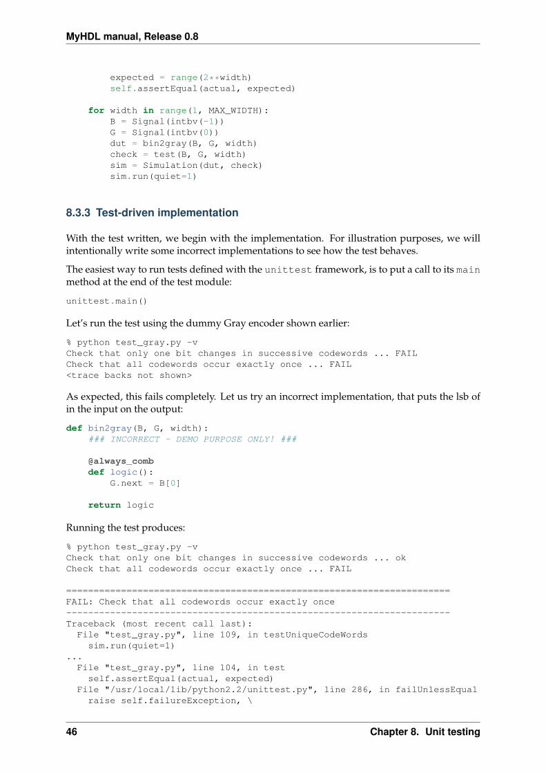
MyHDL manual, Release 0.8
expected = range(2**width)self.assertEqual(actual, expected)
for width in range(1, MAX_WIDTH):B = Signal(intbv(-1))G = Signal(intbv(0))dut = bin2gray(B, G, width)check = test(B, G, width)sim = Simulation(dut, check)sim.run(quiet=1)
8.3.3 Test-driven implementation
With the test written, we begin with the implementation. For illustration purposes, we willintentionally write some incorrect implementations to see how the test behaves.
The easiest way to run tests defined with the unittest framework, is to put a call to its mainmethod at the end of the test module:
unittest.main()
Let’s run the test using the dummy Gray encoder shown earlier:
% python test_gray.py -vCheck that only one bit changes in successive codewords ... FAILCheck that all codewords occur exactly once ... FAIL<trace backs not shown>
As expected, this fails completely. Let us try an incorrect implementation, that puts the lsb ofin the input on the output:
def bin2gray(B, G, width):### INCORRECT - DEMO PURPOSE ONLY! ###
@always_combdef logic():
G.next = B[0]
return logic
Running the test produces:
% python test_gray.py -vCheck that only one bit changes in successive codewords ... okCheck that all codewords occur exactly once ... FAIL
======================================================================FAIL: Check that all codewords occur exactly once----------------------------------------------------------------------Traceback (most recent call last):
File "test_gray.py", line 109, in testUniqueCodeWordssim.run(quiet=1)
...File "test_gray.py", line 104, in test
self.assertEqual(actual, expected)File "/usr/local/lib/python2.2/unittest.py", line 286, in failUnlessEqual
raise self.failureException, \
46 Chapter 8. Unit testing

MyHDL manual, Release 0.8
AssertionError: [0, 0, 1, 1] != [0, 1, 2, 3]
----------------------------------------------------------------------Ran 2 tests in 0.785s
Now the test passes the first requirement, as expected, but fails the second one. After the testfeedback, a full traceback is shown that can help to debug the test output.
Finally, if we use the correct implementation as in section Bit indexing, the output is:
% python test_gray.py -vCheck that only one bit changes in successive codewords ... okCheck that all codewords occur exactly once ... ok
----------------------------------------------------------------------Ran 2 tests in 6.364s
OK
8.3.4 Changing requirements
In the previous section, we concentrated on the general requirements of a Gray code. It ispossible to specify these without specifying the actual code. It is easy to see that there areseveral codes that satisfy these requirements. In good XP style, we only tested the requirementsand nothing more.
It may be that more control is needed. For example, the requirement may be for a particularcode, instead of compliance with general properties. As an illustration, we will show how totest for the original Gray code, which is one specific instance that satisfies the requirements ofthe previous section. In this particular case, this test will actually be easier than the previousone.
We denote the original Gray code of order n as Ln. Some examples:
L1 = [’0’, ’1’]L2 = [’00’, ’01’, ’11’, ’10’]L3 = [’000’, ’001’, ’011’, ’010’, ’110’, ’111’, ’101’, 100’]
It is possible to specify these codes by a recursive algorithm, as follows:
1. L1 = [‘0’, ‘1’]
2. Ln+1 can be obtained from Ln as follows. Create a new code Ln0 by prefixing all code-words of Ln with ‘0’. Create another new code Ln1 by prefixing all codewords of Ln with‘1’, and reversing their order. Ln+1 is the concatenation of Ln0 and Ln1.
Python is well-known for its elegant algorithmic descriptions, and this is a good example. Wecan write the algorithm in Python as follows:
def nextLn(Ln):""" Return Gray code Ln+1, given Ln. """Ln0 = [’0’ + codeword for codeword in Ln]Ln1 = [’1’ + codeword for codeword in Ln]Ln1.reverse()return Ln0 + Ln1
8.3. Unit test development 47
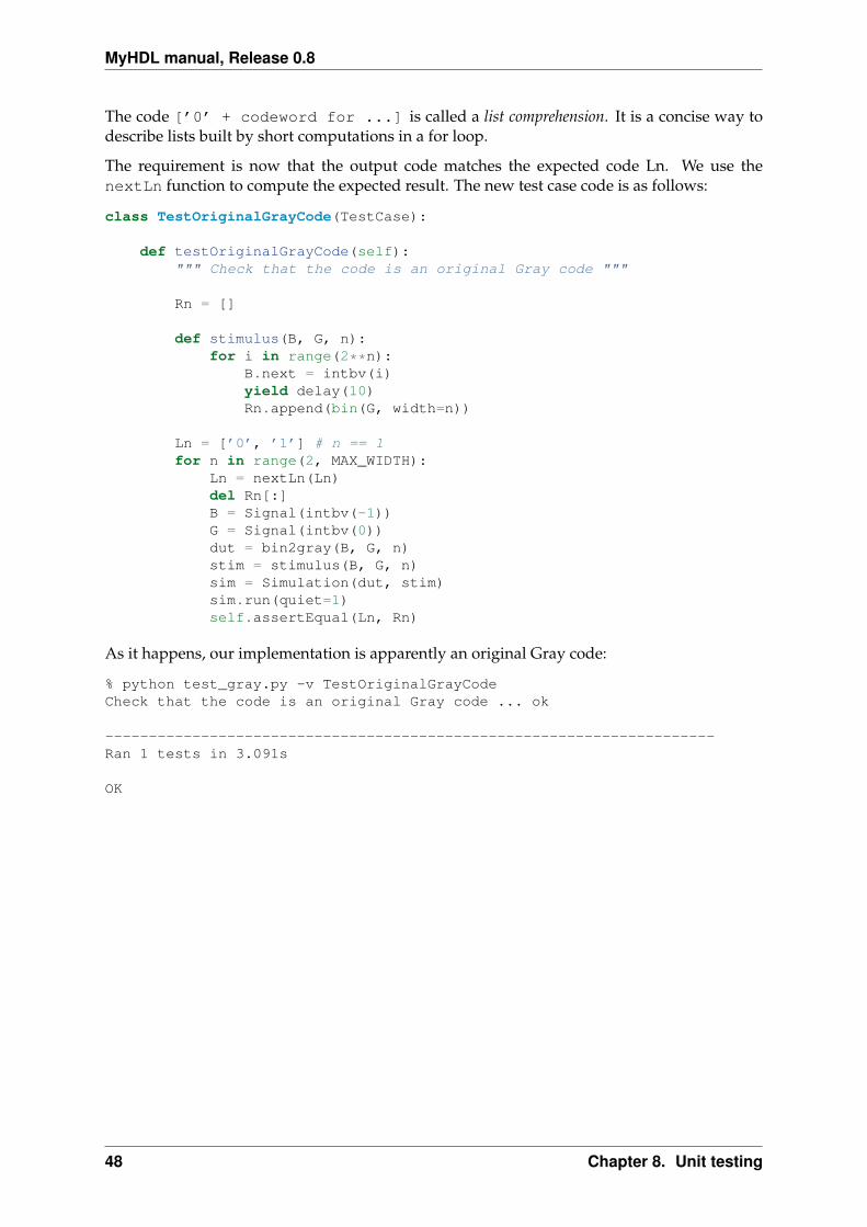
MyHDL manual, Release 0.8
The code [’0’ + codeword for ...] is called a list comprehension. It is a concise way todescribe lists built by short computations in a for loop.
The requirement is now that the output code matches the expected code Ln. We use thenextLn function to compute the expected result. The new test case code is as follows:
class TestOriginalGrayCode(TestCase):
def testOriginalGrayCode(self):""" Check that the code is an original Gray code """
Rn = []
def stimulus(B, G, n):for i in range(2**n):
B.next = intbv(i)yield delay(10)Rn.append(bin(G, width=n))
Ln = [’0’, ’1’] # n == 1for n in range(2, MAX_WIDTH):
Ln = nextLn(Ln)del Rn[:]B = Signal(intbv(-1))G = Signal(intbv(0))dut = bin2gray(B, G, n)stim = stimulus(B, G, n)sim = Simulation(dut, stim)sim.run(quiet=1)self.assertEqual(Ln, Rn)
As it happens, our implementation is apparently an original Gray code:
% python test_gray.py -v TestOriginalGrayCodeCheck that the code is an original Gray code ... ok
----------------------------------------------------------------------Ran 1 tests in 3.091s
OK
48 Chapter 8. Unit testing

CHAPTER 9
Co-simulation with Verilog
9.1 Introduction
One of the most exciting possibilities of MyHDLis to use it as a hardware verification language(HVL). A HVL is a language used to write test benches and verification environments, and tocontrol simulations.
Nowadays, it is generally acknowledged that HVLs should be equipped with modern soft-ware techniques, such as object orientation. The reason is that verification it the most complexand time-consuming task of the design process. Consequently, every useful technique is wel-come. Moreover, test benches are not required to be implementable. Therefore, unlike withsynthesizable code, there are no constraints on creativity.
Technically, verification of a design implemented in another language requires co-simulation.MyHDL is enabled for co-simulation with any HDL simulator that has a procedural languageinterface (PLI). The MyHDLside is designed to be independent of a particular simulator, Onthe other hand, for each HDL simulator a specific PLI module will have to be written in C.Currently, the MyHDL release contains a PLI module for two Verilog simulators: Icarus andCver.
9.2 The HDL side
To introduce co-simulation, we will continue to use the Gray encoder example from the previ-ous chapters. Suppose that we want to synthesize it and write it in Verilog for that purpose.Clearly we would like to reuse our unit test verification environment.
To start, let’s recall how the Gray encoder in MyHDL looks like:
def bin2gray(B, G, width):""" Gray encoder.
B -- input intbv signal, binary encodedG -- output intbv signal, gray encodedwidth -- bit width"""
@always_combdef logic():
for i in range(width):G.next[i] = B[i+1] ^ B[i]
49

MyHDL manual, Release 0.8
return logic
To show the co-simulation flow, we don’t need the Verilog implementation yet, but only theinterface. Our Gray encoder in Verilog would have the following interface:
module bin2gray(B, G);
parameter width = 8;input [width-1:0] B;output [width-1:0] G;....
To write a test bench, one creates a new module that instantiates the design under test (DUT).The test bench declares nets and regs (or signals in VHDL) that are attached to the DUT, and tostimulus generators and response checkers. In an all-HDL flow, the generators and checkersare written in the HDL itself, but we will want to write them in MyHDL. To make the connec-tion, we need to declare which regs & nets are driven and read by the MyHDLsimulator. Forour example, this is done as follows:
module dut_bin2gray;
reg [‘width-1:0] B;wire [‘width-1:0] G;
initial begin$from_myhdl(B);$to_myhdl(G);
end
bin2gray dut (.B(B), .G(G));defparam dut.width = ‘width;
endmodule
The $from_myhdl task call declares which regs are driven by MyHDL, and the $to_myhdltask call which regs & nets are read by it. These tasks take an arbitrary number of arguments.They are defined in a PLI module written in C and made available in a simulator-dependentmanner. In Icarus Verilog, the tasks are defined in a myhdl.vpi module that is compiled fromC source code.
9.3 The MyHDL side
MyHDL supports co-simulation by a Cosimulation object. A Cosimulation object mustknow how to run a HDL simulation. Therefore, the first argument to its constructor is a com-mand string to execute a simulation.
The way to generate and run an simulation executable is simulator dependent. For example, inIcarus Verilog, a simulation executable for our example can be obtained obtained by runningthe iverilog compiler as follows:
% iverilog -o bin2gray -Dwidth=4 bin2gray.v dut_bin2gray.v
This generates a bin2gray executable for a parameter width of 4, by compiling the contribut-ing Verilog files.
50 Chapter 9. Co-simulation with Verilog
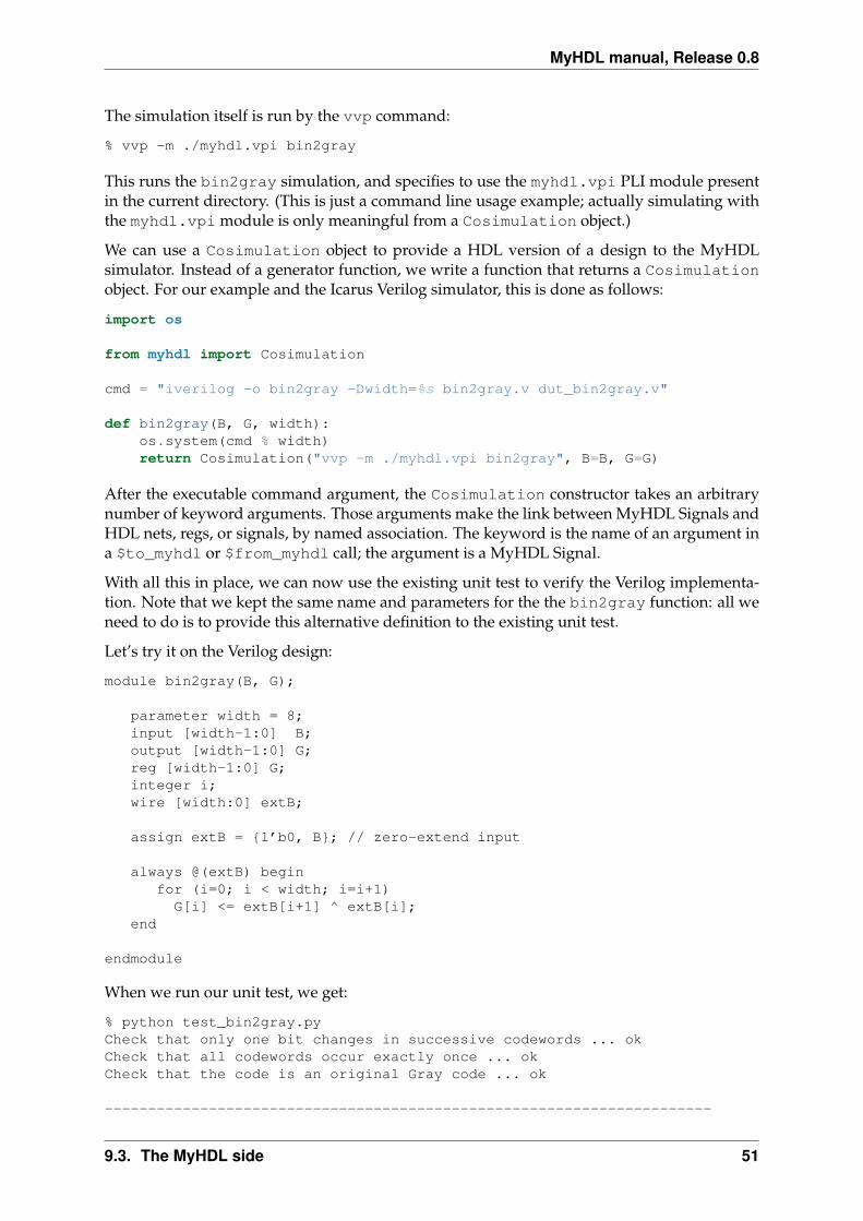
MyHDL manual, Release 0.8
The simulation itself is run by the vvp command:
% vvp -m ./myhdl.vpi bin2gray
This runs the bin2gray simulation, and specifies to use the myhdl.vpi PLI module presentin the current directory. (This is just a command line usage example; actually simulating withthe myhdl.vpi module is only meaningful from a Cosimulation object.)
We can use a Cosimulation object to provide a HDL version of a design to the MyHDLsimulator. Instead of a generator function, we write a function that returns a Cosimulationobject. For our example and the Icarus Verilog simulator, this is done as follows:
import os
from myhdl import Cosimulation
cmd = "iverilog -o bin2gray -Dwidth=%s bin2gray.v dut_bin2gray.v"
def bin2gray(B, G, width):os.system(cmd % width)return Cosimulation("vvp -m ./myhdl.vpi bin2gray", B=B, G=G)
After the executable command argument, the Cosimulation constructor takes an arbitrarynumber of keyword arguments. Those arguments make the link between MyHDL Signals andHDL nets, regs, or signals, by named association. The keyword is the name of an argument ina $to_myhdl or $from_myhdl call; the argument is a MyHDL Signal.
With all this in place, we can now use the existing unit test to verify the Verilog implementa-tion. Note that we kept the same name and parameters for the the bin2gray function: all weneed to do is to provide this alternative definition to the existing unit test.
Let’s try it on the Verilog design:
module bin2gray(B, G);
parameter width = 8;input [width-1:0] B;output [width-1:0] G;reg [width-1:0] G;integer i;wire [width:0] extB;
assign extB = {1’b0, B}; // zero-extend input
always @(extB) beginfor (i=0; i < width; i=i+1)
G[i] <= extB[i+1] ^ extB[i];end
endmodule
When we run our unit test, we get:
% python test_bin2gray.pyCheck that only one bit changes in successive codewords ... okCheck that all codewords occur exactly once ... okCheck that the code is an original Gray code ... ok
----------------------------------------------------------------------
9.3. The MyHDL side 51
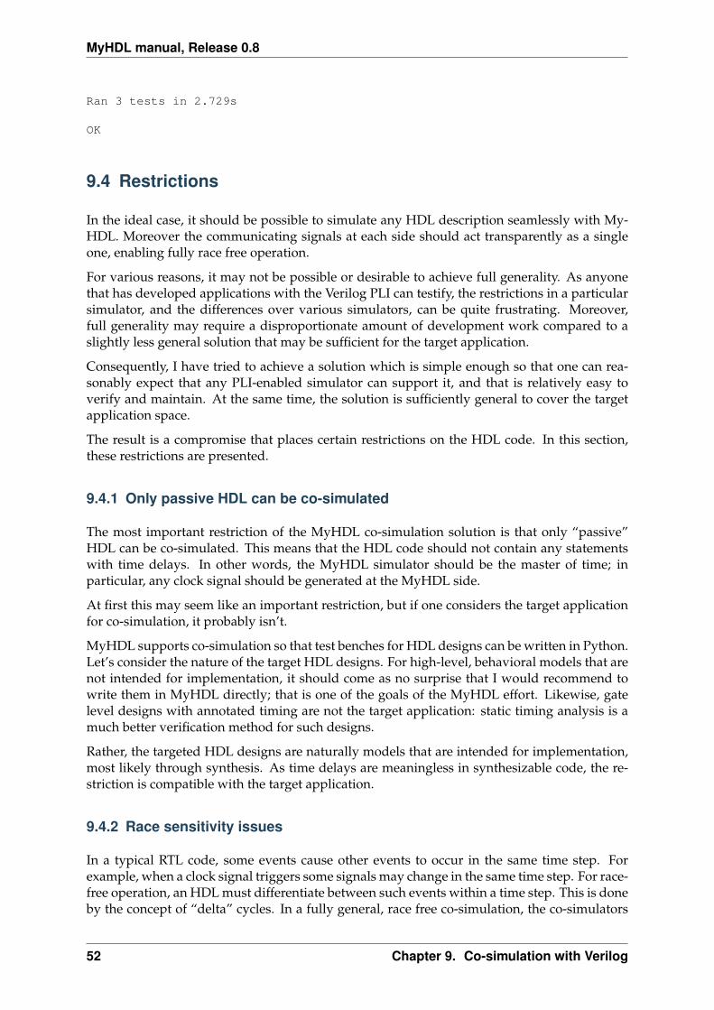
MyHDL manual, Release 0.8
Ran 3 tests in 2.729s
OK
9.4 Restrictions
In the ideal case, it should be possible to simulate any HDL description seamlessly with My-HDL. Moreover the communicating signals at each side should act transparently as a singleone, enabling fully race free operation.
For various reasons, it may not be possible or desirable to achieve full generality. As anyonethat has developed applications with the Verilog PLI can testify, the restrictions in a particularsimulator, and the differences over various simulators, can be quite frustrating. Moreover,full generality may require a disproportionate amount of development work compared to aslightly less general solution that may be sufficient for the target application.
Consequently, I have tried to achieve a solution which is simple enough so that one can rea-sonably expect that any PLI-enabled simulator can support it, and that is relatively easy toverify and maintain. At the same time, the solution is sufficiently general to cover the targetapplication space.
The result is a compromise that places certain restrictions on the HDL code. In this section,these restrictions are presented.
9.4.1 Only passive HDL can be co-simulated
The most important restriction of the MyHDL co-simulation solution is that only “passive”HDL can be co-simulated. This means that the HDL code should not contain any statementswith time delays. In other words, the MyHDL simulator should be the master of time; inparticular, any clock signal should be generated at the MyHDL side.
At first this may seem like an important restriction, but if one considers the target applicationfor co-simulation, it probably isn’t.
MyHDL supports co-simulation so that test benches for HDL designs can be written in Python.Let’s consider the nature of the target HDL designs. For high-level, behavioral models that arenot intended for implementation, it should come as no surprise that I would recommend towrite them in MyHDL directly; that is one of the goals of the MyHDL effort. Likewise, gatelevel designs with annotated timing are not the target application: static timing analysis is amuch better verification method for such designs.
Rather, the targeted HDL designs are naturally models that are intended for implementation,most likely through synthesis. As time delays are meaningless in synthesizable code, the re-striction is compatible with the target application.
9.4.2 Race sensitivity issues
In a typical RTL code, some events cause other events to occur in the same time step. Forexample, when a clock signal triggers some signals may change in the same time step. For race-free operation, an HDL must differentiate between such events within a time step. This is doneby the concept of “delta” cycles. In a fully general, race free co-simulation, the co-simulators
52 Chapter 9. Co-simulation with Verilog
MyHDL manual, Release 0.8
would communicate at the level of delta cycles. However, in MyHDL co-simulation, this is notentirely the case.
Delta cycles from the MyHDL simulator toward the HDL co-simulator are preserved. How-ever, in the opposite direction, they are not. The signals changes are only returned to theMyHDL simulator after all delta cycles have been performed in the HDL co-simulator.
What does this mean? Let’s start with the good news. As explained in the previous section, theconcept behind MyHDL co-simulation implies that clocks are generated at the MyHDL side.When using a MyHDL clock and its corresponding HDL signal directly as a clock, co-simulation is racefree. In other words, the case that most closely reflects the MyHDL co-simulation approach, israce free.
The situation is different when you want to use a signal driven by the HDL (and the corre-sponding MyHDL signal) as a clock. Communication triggered by such a clock is not race free.The solution is to treat such an interface as a chip interface instead of an RTL interface. Forexample, when data is triggered at positive clock edges, it can safely be sampled at negativeclock edges. Alternatively, the MyHDL data signals can be declared with a delay value, so thatthey are guaranteed to change after the clock edge.
9.5 Implementation notes
This section requires some knowledge of PLI terminology.
Enabling a simulator for co-simulation requires a PLI module written in C. In Verilog, the PLIis part of the “standard”. However, different simulators implement different versions andportions of the standard. Worse yet, the behavior of certain PLI callbacks is not defined onsome essential points. As a result, one should plan to write or at least customize a specific PLImodule for any simulator. The release contains a PLI module for the open source Icarus andCver simulators.
This section documents the current approach and status of the PLI module implementationand some reflections on future implementations.
9.5.1 Icarus Verilog
Delta cycle implementation
To make co-simulation work, a specific type of PLI callback is needed. The callback shouldbe run when all pending events have been processed, while allowing the creation of newevents in the current time step (e.g. by the MyHDL simulator). In some Verilog simulators, thecbReadWriteSync callback does exactly that. However, in others, including Icarus, it doesnot. The callback’s behavior is not fully standardized; some simulators run the callback beforenon- blocking assignment events have been processed.
Consequently, I had to look for a workaround. One half of the solution is to use thecbReadOnlySync callback. This callback runs after all pending events have been processed.However, it does not permit to create new events in the current time step. The second halfof the solution is to map MyHDL delta cycles onto real Verilog time steps. Note that fortu-nately I had some freedom here because of the restriction that only passive HDL code can beco-simulated.
9.5. Implementation notes 53

MyHDL manual, Release 0.8
I chose to make the time granularity in the Verilog simulator a 1000 times finer than in the My-HDL simulator. For each MyHDL time step, 1000 Verilog time steps are available for MyHDLdelta cycles. In practice, only a few delta cycles per time step should be needed. Exceedingthis limit almost certainly indicates a design error; the limit is checked at run-time. The factor1000 also makes it easy to distinguish “real” time from delta cycle time when printing out theVerilog time.
Passive Verilog check
As explained before, co-simulated Verilog should not contain delay statements. Ideally, thereshould be a run-time check to flag non-compliant code. However, there is currently no suchcheck in the Icarus module.
The check can be written using the cbNextSimTime VPI callback in Verilog. However, Icarus0.7 doesn’t support this callback. In the meantime, support for it has been added to the Icarusdevelopment branch. When Icarus 0.8 is released, a check will be added.
In the mean time, just don’t do this. It may appear to “work” but it really won’t as events willbe missed over the co-simulation interface.
9.5.2 Cver
MyHDL co-simulation is supported with the open source Verilog simulator Cver. The PLImodule is based on the one for Icarus and basically has the same functionality. Only somecosmetic modifications were required.
9.5.3 Other Verilog simulators
The Icarus module is written with VPI calls, which are provided by the most recent generationof the Verilog PLI. Some simulators may only support TF/ACC calls, requiring a completeredesign of the interface module.
If the simulator supports VPI, the Icarus module should be reusable to a large extent. How-ever, it may be possible to improve on it. The workaround to support delta cycles de-scribed in Section Delta cycle implementation may not be necessary. In some simulators, thecbReadWriteSync callback occurs after all events (including non-blocking assignments)have been processed. In that case, the functionality can be supported without a finer timegranularity in the Verilog simulator.
There are also Verilog standardization efforts underway to resolve the ambiguity of thecbReadWriteSync callback. The solution will be to introduce new, well defined callbacks.From reading some proposals, I conclude that the cbEndOfSimTime callback would providethe required functionality.
The MyHDL project currently has no access to commercial Verilog simulators, so progress inco-simulation support depends on external interest and participation. Users have reportedthat they are using MyHDL co-simulation with the simulators from Aldec and Modelsim.
54 Chapter 9. Co-simulation with Verilog
MyHDL manual, Release 0.8
9.5.4 Interrupted system calls
The PLI module uses read and write system calls to communicate between the co-simulators. The implementation assumes that these calls are restarted automatically by theoperating system when interrupted. This is apparently what happens on the Linux box onwhich MyHDL is developed.
It is known how non-restarted interrupted system calls should be handled, but currently suchcode cannot be tested on the MyHDL development platform. Also, it is not clear whetherthis is still a relevant issue with modern operating systems. Therefore, this issue has not beenaddressed at this moment. However, assertions have been included that should trigger whenthis situation occurs.
Whenever an assertion fires in the PLI module, please report it. The same holds for Pythonexceptions that cannot be easily explained.
9.5.5 What about VHDL?
It would be nice to have an interface to VHDL simulators such as the Modelsim VHDL simu-lator. Let us summarize the requirements to accomplish that:
• We need a procedural interface to the internals of the simulator.
• The procedural interface should be a widely used industry standard so that we can reusethe work in several simulators.
• MyHDL is an open-source project and therefore there should be also be an open-sourcesimulator that implements the procedural interface.
vpi for Verilog matches these requirements. It is a widely used standard and is supported bythe open-source Verilog simulators Icarus and cver.
However, for VHDL the situation is different. While there exists a standard called vhpi, itmuch less popular than vpi. Also, to our knowledge there is only one credible open sourceVHDL simulator (GHDL) and it is unclear whether it has vhpi capabilities that are powerfulenough for MyHDL’s purposes.
Consequently, the development of co-simulation for VHDL is currently on hold. For someapplications, there is an alternative: see Conversion of test benches.
9.5. Implementation notes 55

MyHDL manual, Release 0.8
56 Chapter 9. Co-simulation with Verilog

CHAPTER 10
Conversion to Verilog and VHDL
10.1 Introduction
Subject to some limitations, MyHDL supports the automatic conversion of MyHDL code toVerilog or VHDL code. This feature provides a path from MyHDL into a standard Verilog orVHDL based design environment.
This chapter describes the concepts of conversion. Concrete examples can be found in thecompanion chapter Conversion examples.
10.2 Solution description
To be convertible, the hardware description should satisfy certain restrictions, defined as theconvertible subset. This is described in detail in The convertible subset.
A convertible design can be converted to an equivalent model in Verilog or VHDL, using thefunction toVerilog() or toVHDL() from the MyHDL library.
When the design is intended for implementation a third-party synthesis tool is used to compilethe Verilog or VHDL model into an implementation for an ASIC or FPGA. With this step, thereis an automated path from a hardware description in Python to an FPGA or ASIC implemen-tation.
The conversion does not start from source files, but from an instantiated design that has beenelaborated by the Python interpreter. The converter uses the Python profiler to track the in-terpreter’s operation and to infer the design structure and name spaces. It then selectivelycompiles pieces of source code for additional analysis and for conversion.
10.3 Features
Conversion after elaboration Elaboration refers to the initial processing of a hardware descrip-tion to achieve a representation of a design instance that is ready for simulation or syn-thesis. In particular, structural parameters and constructs are processed in this step. InMyHDL, the Python interpreter itself is used for elaboration. A Simulation object isconstructed with elaborated design instances as arguments. Likewise, conversion workson an elaborated design instance. The Python interpreter is thus used as much as possi-ble.
57
MyHDL manual, Release 0.8
Arbitrarily complex structure As the conversion works on an elaborated design instance, anymodeling constraints only apply to the leaf elements of the design structure, that is, theco-operating generators. In other words, there are no restrictions on the description ofthe design structure: Python’s full power can be used for that purpose. Also, the designhierarchy can be arbitrarily deep.
Generator are mapped to Verilog or VHDL constructs The converter analyzes the code ofeach generator and maps it to equivalent constructs in the target HDL. For Verilog, itwill map generators to always blocks, continuous assignments or initial blocks. ForVHDL, it will map them to process statements or concurrent signal assignments.
The module ports are inferred from signal usage In MyHDL, the input or output directionof interface signals is not explicitly declared. The converter investigates signal usage inthe design hierarchy to infer whether a signal is used as input, output, or as an internalsignal.
Interfaces are expanded MyHDL provides a power mechanism to define complex module in-terfaces. These interfaces are name extended to individual signals in the target HDL(Verilog and VHDL). This enables MyHDL to support higher-level abstractions that arenot available in the target HDL.
Function calls are mapped to Verilog or VHDL subprograms The converter analyzes func-tion calls and function code. Each function is mapped to an appropriate subprogramin the target HDL: a function or task in Verilog, and a function or procedure in VHDL. Inorder to support the full power of Python functions, a unique subprogram is generatedper Python function call.
If-then-else structures may be mapped to case statements Python does not provide a casestatement. However, the converter recognizes if-then-else structures in which a variableis sequentially compared to items of an enumeration type, and maps such a structure toa Verilog or VHDL case statement with the appropriate synthesis attributes.
Choice of encoding schemes for enumeration types The enum() function in MyHDL re-turns an enumeration type. This function takes an additional parameter encoding thatspecifies the desired encoding in the implementation: binary, one hot, or one cold. Theconverter generates the appropriate code for the specified encoding.
RAM memory Certain synthesis tools can map Verilog memories or VHDL arrays to RAMstructures. To support this interesting feature, the converter maps lists of signals to Ver-ilog memories or VHDL arrays.
ROM memory Some synthesis tools can infer a ROM from a case statement. The converterdoes the expansion into a case statement automatically, based on a higher level descrip-tion. The ROM access is described in a single line, by indexing into a tuple of integers.
Signed arithmetic In MyHDL, working with negative numbers is trivial: one just uses anintbv object with an appropriate constraint on its values. In contrast, both Verilog andVHDL make a difference between an unsigned and a signed representation. To workwith negative values, the user has to declare a signed variable explicitly. But when signedand unsigned operands are mixed in an expression, things may become tricky.
In Verilog, when signed and unsigned operands are mixed, all operands are interpretedas unsigned. Obviously, this leads to unexpected results. The designer will have to addsign extensions and type casts to solve this.
In VHDL, mixing signed and unsigned will generally not work. The designer will haveto match the operands manually by adding resizings and type casts.
58 Chapter 10. Conversion to Verilog and VHDL
MyHDL manual, Release 0.8
In MyHDL, these issues don’t exist because intbv objects simply work as (constrained)integers. Moreover, the convertor automates the cumbersome tasks that are requiredin Verilog and VHDL. It uses signed or unsigned types based on the value constraintsof the intbv objects, and automatically performs the required sign extensions, resizings,and type casts.
User-defined code If desired, the user can bypass the conversion process and describe user-defined code to be inserted instead.
10.4 The convertible subset
10.4.1 Introduction
Unsurprisingly, not all MyHDL code can be converted. Although the restrictions are signif-icant, the convertible subset is much broader than the RTL synthesis subset which is an in-dustry standard. In other words, MyHDL code written according to the RTL synthesis rules,should always be convertible. However, it is also possible to write convertible code for non-synthesizable models or test benches.
The converter attempts to issue clear error messages when it encounters a construct that cannotbe converted.
Recall that any restrictions only apply to the design after elaboration. In practice, this meansthat they apply only to the code of the generators, that are the leaf functional blocks in a My-HDL design.
10.4.2 Coding style
A natural restriction on convertible code is that it should be written in MyHDL style: cooper-ating generators, communicating through signals, and with sensitivity specify resume condi-tions.
For pure modeling, it doesn’t matter how generators are created. However, in convertiblecode they should be created using one of the MyHDL decorators: instance(), always(),always_seq(), or always_comb().
10.4.3 Supported types
The most important restriction regards object types. Only a limited amount of types can beconverted. Python int and long objects are mapped to Verilog or VHDL integers. All othersupported types need to have a defined bit width. The supported types are the Python booltype, the MyHDL intbv type, and MyHDL enumeration types returned by function enum().
intbv objects must be constructed so that a bit width can be inferred. This can be done byspecifying minimum and maximum values, e.g. as follows:
index = intbv(0, min=MIN, max=MAX)
The Verilog converter supports intbv objects that can take negative values.
Alternatively, a slice can be taken from an intbv object as follows:
10.4. The convertible subset 59

MyHDL manual, Release 0.8
index = intbv(0)[N:]
Such as slice returns a new intbv object, with minimum value 0 , and maximum value 2**N.
In addition to the scalar types described above, the convertor also supports a number of tupleand list based types. The mapping from MyHDL types is summarized in the following table.
MyHDL type VHDL type Notes Verilog type Notesint integer integerbool std_logic (1) regintbv with min >= 0 unsigned (2) regintbv with min < 0 signed (2) reg signedenum dedicated
enumeration typereg
tuple of int mapped to casestatement
(3) mapped to casestatement
(3)
list of bool array ofstd_logic
reg (5)
list of intbv with min>= 0
array of unsigned (4) reg (4)(5)
list of intbv with min< 0
array of signed (4) reg signed (4)(5)
Notes:
1. The VHDL std_logic type is defined in the standard VHDL packageIEEE.std_logic_1164.
2. The VHDL unsigned and signed types used are those from the standard VHDL pack-ages IEEE.numeric_std.
3. A MyHDL tuple of int is used for ROM inference, and can only be used in a veryspecific way: an indexing operation into the tuple should be the rhs of an assignment.
4. All list members should have identical value constraints.
5. Lists are mapped to Verilog memories.
The table as presented applies to MyHDL variables. The convertor also supports MyHDLsignals that use bool, intbv or enum objects as their underlying type. For VHDL, these aremapped to VHDL signals with an underlying type as specified in the table above. Verilogdoesn’t have the signal concept. For Verilog, a MyHDL signal is mapped to a Verilog reg asin the table above, or to a Verilog wire, depending on the signal usage.
The convertor supports MyHDL list of signals provided the underlying signal type is eitherbool or intbv. They may be mapped to a VHDL signal with a VHDL type as specifiedin the table, or to a Verilog memory. However, list of signals are not always mapped to acorresponding VHDL or Verilog object. See Conversion of lists of signals for more info.
10.4.4 Supported statements
The following is a list of the statements that are supported by the Verilog converter, possiblyqualified with restrictions or usage notes.
assert An assert statement in Python looks as follow:
60 Chapter 10. Conversion to Verilog and VHDL

MyHDL manual, Release 0.8
assert test_expression
It can be converted provided test_expression is convertible.
break
continue
def
for The only supported iteration scheme is iterating through sequences of integers returnedby built-in function range() or MyHDL function downrange(). The optional elseclause is not supported.
if if, elif, and else clauses are fully supported.
pass
A print statement with multiple arguments:
print arg1, arg2, ...
is supported. However, there are restrictions on the arguments. First, they shouldbe of one of the following forms:
argformatstring % argformatstring % (arg1, arg2, ...)
where arg is a bool, int, intbv, enum, or a Signal of these types.
The formatstring contains ordinary characters and conversion specifiers as inPython. However, the only supported conversion specifiers are %s and %d. Justifi-cation and width specification are thus not supported.
Printing without a newline:
print arg1 ,
is not supported.
raise This statement is mapped to statements that end the simulation with an error message.
return
yield A yield expression is used to specify a sensitivity list. The yielded expression canbe a Signal, a signal edge as specified by MyHDL functions Signal.posedge orSignal.negedge, or a tuple of signals and edge specifications. It can also be a delay()object.
while The optional else clause is not supported.
10.4.5 Supported built-in functions
The following is a list of the built-in functions that are supported by the converter.
bool() This function can be used to typecast an object explicitly to its boolean interpretation.
len() For Signal and intbv objects, function len() returns the bit width.
10.4. The convertible subset 61

MyHDL manual, Release 0.8
int() This function can be used to typecast an object explicitly to its integer interpretation.
10.4.6 Docstrings
The convertor propagates comments under the form of Python docstrings.
Docstrings are typically used in Python to document certain objects in a standard way. Such“official” docstrings are put into the converted output at appropriate locations. The convertorsupports official docstrings for the top level module and for generators.
Within generators, “nonofficial” docstrings are propagated also. These are strings (triplequoted by convention) that can occur anywhere between statements.
Regular Python comments are ignored by the Python parser, and they are not present in theparse tree. Therefore, these are not propagated. With docstrings, you have an elegant way tospecify which comments should be propagated and which not.
10.5 Conversion of lists of signals
Lists of signals are useful for many purposes. For example, they make it easy to create arepetitive structure. Another application is the description of memory behavior.
The convertor output is non-hierarchical. That implies that all signals are declared at the top-level in VHDL or Verilog (as VHDL signals, or Verilog regs and wires.) However, some signalsthat are a list member at some level in the MyHDL design hierarchy may be used as a plainsignal at a lower level. For such signals, a choice has to be made whether to declare a Verilogmemory or VHDL array, or a number of plain signal names.
If possible, plain signal declarations are preferred, because Verilog memories and arrays havesome restrictions in usage and tool support. This is possible if the list syntax is strictly usedoutside generator code, for example when lists of signals are used to describe structure.
Conversely, when list syntax is used in some generator, then a Verilog memory or VHDL arraywill be declared. The typical example is the description of RAM memories.
10.6 Conversion of Interfaces
Interfaces simplify the complicated interconnect between modules. In MyHDL the interfacesprovide an intuitive approach to group logically related ports. The grouping of ports has manybenefits such as reducing complexity and increasing modularity.
The converter will name extend the interfaces during conversion, in the converted code eachattribute will appear as a individual signal. Because the hierarchy is flattened the name ex-tension may need to include information on the where in the hierarchy the interface occurs toprevent name collisions.
62 Chapter 10. Conversion to Verilog and VHDL

MyHDL manual, Release 0.8
10.7 Assignment issues
10.7.1 Name assignment in Python
Name assignment in Python is a different concept than in many other languages. This point isvery important for effective modeling in Python, and even more so for synthesizable MyHDLcode. Therefore, the issues are discussed here explicitly.
Consider the following name assignments:
a = 4a = ‘‘a string’’a = False
In many languages, the meaning would be that an existing variable a gets a number of differentvalues. In Python, such a concept of a variable doesn’t exist. Instead, assignment merelycreates a new binding of a name to a certain object, that replaces any previous binding. So inthe example, the name a is bound a number of different objects in sequence.
The converter has to investigate name assignment and usage in MyHDL code, and to mapnames to Verilog or VHDL objects. To achieve that, it tries to infer the type and possibly thebit width of each expression that is assigned to a name.
Multiple assignments to the same name can be supported if it can be determined that a con-sistent type and bit width is being used in the assignments. This can be done for booleanexpressions, numeric expressions, and enumeration type literals.
In other cases, a single assignment should be used when an object is created. Subsequent valuechanges are then achieved by modification of an existing object. This technique should be usedfor Signal and intbv objects.
10.7.2 Signal assignment
Signal assignment in MyHDL is implemented using attribute assignment to attribute next.Value changes are thus modeled by modification of the existing object. The converter investi-gates the Signal object to infer the type and bit width of the corresponding Verilog or VHDLobject.
10.7.3 intbv objects
Type intbv is likely to be the workhorse for synthesizable modeling in MyHDL. An intbvinstance behaves like a (mutable) integer whose individual bits can be accessed and modified.Also, it is possible to constrain its set of values. In addition to error checking, this makes itpossible to infer a bit width, which is required for implementation.
As noted before, it is not possible to modify value of an intbv object using name assignment.In the following, we will show how it can be done instead. Consider:
a = intbv(0)[8:]
This is an intbv object with initial value 0 and bit width 8. To change its value to 5, we canuse slice assignment:
10.7. Assignment issues 63
MyHDL manual, Release 0.8
a[8:] = 5
The same can be achieved by leaving the bit width unspecified, which has the meaning tochange “all” bits:
a[:] = 5
Often the new value will depend on the old one. For example, to increment an intbv with thetechnique above:
a[:] = a + 1
Python also provides augmented assignment operators, which can be used to implement in-place operations. These are supported on intbv objects and by the converter, so that theincrement can also be done as follows:
a += 1
10.8 Excluding code from conversion
For some tasks, such as debugging, it may be useful to insert arbitrary Python code that shouldnot be converted.
The convertor supports this by ignoring all code that is embedded in a if __debug__ test.The value of the __debug__ variable is not taken into account.
10.9 User-defined code
MyHDL provides a way to include user-defined code during the conversion process. There arespecial function attributes that are understood by the converter but ignored by the simulator.The attributes are verilog_code for Verilog and vhdl_code for VHDL. They operate like aspecial return value. When defined in a MyHDL function, the convertor will use their valueinstead of the regular return value. Effectively, it will stop converting at that point.
The value of verilog_code or vhdl_code should be a Python template string. A templatestring supports $-based substitutions. The $name notation can be used to refer to the variablenames in the context of the string. The convertor will substitute the appropriate values in thestring and then insert it instead of the regular converted output.
There is one more issue with user-defined code. Normally, the converter infers inputs, inter-nal signals, and outputs. It also detects undriven and multiple driven signals. To do this, itassumes that signals are not driven by default. It then processes the code to find out whichsignals are driven from where.
Proper signal usage inference cannot be done with user-defined code. Without user help, thiswill result in warnings or errors during the inference process, or in compilation errors frominvalid code. The user can solve this by setting the driven or read attribute for signals thatare driven or read from the user-defined code. These attributes are False by default. Theallowed “true” values of the driven attribute are True, ’wire’ and ’reg’. The latter twovalues specifies how the user-defined Verilog code drives the signal in Verilog. To decide whichvalue to use, consider how the signal should be declared in Verilog after the user-defined codeis inserted.
64 Chapter 10. Conversion to Verilog and VHDL

MyHDL manual, Release 0.8
For an example of user-defined code, see User-defined code.
10.10 Template transformation
Note: This section is only relevant for VHDL.
There is a difference between VHDL and Verilog in the way in which sensitivity to signal edgesis specified. In Verilog, edge specifiers can be used directly in the sensitivity list. In VHDL, thisis not possible: only signals can be used in the sensitivity list. To check for an edge, one usesthe rising_edge() or falling_edge() functions in the code.
MyHDL follows the Verilog scheme to specify edges in the sensitivity list. Consequently, whenmapping such code to VHDL, it needs to be transformed to equivalent VHDL. This is an im-portant issue because it affects all synthesizable templates that infer sequential logic.
We will illustrate this feature with some examples. This is the MyHDL code for a D flip-flop:
@always(clk.posedge)def logic():
q.next = d
It is converted to VHDL as follows:
DFF_LOGIC: process (clk) isbegin
if rising_edge(clk) thenq <= d;
end if;end process DFF_LOGIC;
The convertor can handle the more general case. For example, this is MyHDL code for a Dflip-flop with asynchronous set, asynchronous reset, and preference of set over reset:
@always(clk.posedge, set.negedge, rst.negedge)def logic():
if set == 0:q.next = 1
elif rst == 0:q.next = 0
else:q.next = d
This is converted to VHDL as follows:
DFFSR_LOGIC: process (clk, set, rst) isbegin
if (set = ’0’) thenq <= ’1’;
elsif (rst = ’0’) thenq <= ’0’;
elsif rising_edge(clk) thenq <= d;
end if;end process DFFSR_LOGIC;
10.10. Template transformation 65

MyHDL manual, Release 0.8
All cases with practical utility can be handled in this way. However, there are other cases thatcannot be transformed to equivalent VHDL. The convertor will detect those cases and give anerror.
10.11 Conversion output verification by co-simulation
Note: This section is only relevant for Verilog.
To verify the converted Verilog output, co-simulation can be used. To make this task easier,the converter also generates a test bench that makes it possible to simulate the Verilog designusing the Verilog co-simulation interface. This permits to verify the Verilog code with the sametest bench used for the MyHDL code.
10.12 Conversion of test benches
After conversion, we obviously want to verify that the VHDL or Verilog code works correctly.For Verilog, we can use co-simulation as discussed earlier. However, for VHDL, co-simulationis currently not supported.
An alternative is to convert the test bench itself, so that both test bench and design can be runin the HDL simulator. Of course, this is not a fully general solution, as there are importantconstraints on the kind of code that can be converted. Thus, the question is whether the con-version restrictions permit to develop sufficiently complex test benches. In this section, wepresent some insights about this.
The most important restrictions regard the types that can be used, as discussed earlier in thischapter. However, the “convertible subset” is wider than the “synthesis subset”. We willpresent a number of non-synthesizable feature that are of interest for test benches.
the while loop while loops can be used for high-level control structures.
the raise statement A raise statement can stop the simulation on an error condition.
delay() objects Delay modeling is essential for test benches.
the print statement print statements can be used for simple debugging.
the assert statement. Originally, assert statements were only intended to insert debug-ging assertions in code. Recently, there is a tendency to use them to write self-checkingunit tests, controlled by unit test frameworks such as py.test. In particular, they area powerful way to write self-checking test benches for MyHDL designs. As assertstatements are convertible, a whole unit test suite in MyHDL can be converted to anequivalent test suite in Verilog and VHDL.
Additionally, the same techniques as for synthesizable code can be used to master complexity.In particular, any code outside generators is executed during elaboration, and therefore notconsidered in the conversion process. This feature can for example be used for complex cal-culations that set up constants or expected results. Furthermore, a tuple of ints can be used tohold a table of values that will be mapped to a case statement in Verilog and VHDL.
66 Chapter 10. Conversion to Verilog and VHDL
MyHDL manual, Release 0.8
10.13 Methodology notes
10.13.1 Simulate first
In the Python philosophy, the run-time rules. The Python compiler doesn’t attempt to detecta lot of errors beyond syntax errors, which given Python’s ultra-dynamic nature would be analmost impossible task anyway. To verify a Python program, one should run it, preferablyusing unit testing to verify each feature.
The same philosophy should be used when converting a MyHDL description to Verilog: makesure the simulation runs fine first. Although the converter checks many things and attemptsto issue clear error messages, there is no guarantee that it does a meaningful job unless thesimulation runs fine.
10.13.2 Handling hierarchy
Recall that conversion occurs after elaboration. A consequence is that the converted output isnon-hierarchical. In many cases, this is not an issue. The purpose of conversion is to providea path into a traditional design flow by using Verilog and VHDL as a “back-end” format.Hierarchy is quite relevant to humans, but much less so to tools.
However, in some cases hierarchy is desirable. For example, if you convert a test bench youmay prefer to keep its code separate from the design under test. In other words, conversionshould stop at the design under test instance, and insert an instantiation instead.
There is a workaround to accomplish this with a small amount of additional work. Theworkaround is to define user-defined code consisting of an instantiation of the design undertest. As discussed in User-defined code, when the convertor sees the hook it will stop convertingand insert the instantiation instead. Of course, you will want to convert the design under testitself also. Therefore, you should use a flag that controls whether the hook is defined or notand set it according to the desired conversion.
10.14 Known issues
Verilog and VHDL integers are 32 bit wide Usually, Verilog and VHDL integers are 32 bitwide. In contrast, Python is moving toward integers with undefined width. Pythonint and long variables are mapped to Verilog integers; so for values wider than 32 bitthis mapping is incorrect.
Synthesis pragmas are specified as Verilog comments. The recommended way to specifysynthesis pragmas in Verilog is through attribute lists. However, the Icarus simulatordoesn’t support them for case statements (to specify parallel_case and full_casepragmas). Therefore, the old but deprecated method of synthesis pragmas in Verilogcomments is still used.
Inconsistent place of the sensitivity list inferred from always_comb. The semantics ofalways_comb, both in Verilog and MyHDL, is to have an implicit sensitivity list atthe end of the code. However, this may not be synthesizable. Therefore, the inferredsensitivity list is put at the top of the corresponding always block or process. Thismay cause inconsistent behavior at the start of the simulation. The workaround is tocreate events at time 0.
10.13. Methodology notes 67
MyHDL manual, Release 0.8
68 Chapter 10. Conversion to Verilog and VHDL

CHAPTER 11
Conversion examples
11.1 Introduction
In this chapter, we will demonstrate the conversion process with a number of examples. For theconcepts of MyHDL conversion, read the companion chapter Conversion to Verilog and VHDL.
11.2 A small sequential design
Consider the following MyHDL code for an incrementer module:
ACTIVE_LOW, INACTIVE_HIGH = 0, 1
def Inc(count, enable, clock, reset):
""" Incrementer with enable.
count -- outputenable -- control input, increment when 1clock -- clock inputreset -- asynchronous reset inputn -- counter max value
"""
@always_seq(clock.posedge, reset=reset)def incLogic():
if enable:count.next = count + 1
return incLogic
Normally, to simulate the design, we would elaborate it as follows:
m = 8
count = Signal(modbv(0)[m:])enable = Signal(bool(0))clock = Signal(bool(0))reset = ResetSignal(0, active=0, async=True)
inc_inst = Inc(count, enable, clock, reset)
69

MyHDL manual, Release 0.8
inc_inst is an elaborated design instance that can be simulated. To convert it to Verilog, wechange the last line as follows:
inc_inst = toVerilog(Inc, count, enable, clock, reset, n=n)
Again, this creates an instance that can be simulated, but as a side effect, it also generates anequivalent Verilog module in file Inc.v. The Verilog code looks as follows:
module Inc (count,enable,clock,reset
);
output [7:0] count;reg [7:0] count;input enable;input clock;input reset;
always @(posedge clock, negedge reset) begin: INC_INCLOGICif (reset == 0) begin
count <= 0;endelse begin
if (enable) begincount <= (count + 1);
endend
end
endmodule
The convertor infers a proper Verilog module interface and maps the MyHDL generator to aVerilog always block.
Similarly, we can convert to VHDL as follows:
inc_inst = toVHDL(Inc, count, enable, clock, reset, n=n)
This creates an equivalent VHDL module in file Inc.vhd:
library IEEE;use IEEE.std_logic_1164.all;use IEEE.numeric_std.all;use std.textio.all;
use work.pck_myhdl_08.all;
entity Inc isport (
count: inout unsigned(7 downto 0);enable: in std_logic;clock: in std_logic;reset: in std_logic
);end entity Inc;
70 Chapter 11. Conversion examples

MyHDL manual, Release 0.8
architecture MyHDL of Inc is
begin
INC_INCLOGIC: process (clock, reset) isbegin
if (reset = ’0’) thencount <= (others => ’0’);
elsif rising_edge(clock) thenif bool(enable) then
count <= (count + 1);end if;
end if;end process INC_INCLOGIC;
end architecture MyHDL;
The MyHDL generator is mapped to a VHDL process in this case.
Note that the VHDL file refers to a VHDL package called pck_myhdl_08. This package con-tains a number of convenience functions that make the conversion easier.
Note also the use of an inout in the interface. This is not recommended VHDL design practice,but it is required here to have a valid VHDL design that matches the behavior of the MyHDLdesign. As this is only an issue for ports and as the convertor output is non-hierarchical, theissue is not very common and has an easy workaround.
11.3 A small combinatorial design
The second example is a small combinatorial design, more specifically the binary to Gray codeconverter from previous chapters:
def bin2gray(B, G, width):
""" Gray encoder.
B -- input intbv signal, binary encodedG -- output intbv signal, gray encodedwidth -- bit width
"""
@always_combdef logic():
Bext = intbv(0)[width+1:]Bext[:] = Bfor i in range(width):
G.next[i] = Bext[i+1] ^ Bext[i]
return logic
As before, you can create an instance and convert to Verilog and VHDL as follows:
width = 8
B = Signal(intbv(0)[width:])
11.3. A small combinatorial design 71
MyHDL manual, Release 0.8
G = Signal(intbv(0)[width:])
bin2gray_inst = toVerilog(bin2gray, B, G, width)bin2gray_inst = toVHDL(bin2gray, B, G, width)
The generated Verilog code looks as follows:
module bin2gray (B,G
);
input [7:0] B;output [7:0] G;reg [7:0] G;
always @(B) begin: BIN2GRAY_LOGICinteger i;reg [9-1:0] Bext;Bext = 9’h0;Bext = B;for (i=0; i<8; i=i+1) begin
G[i] <= (Bext[(i + 1)] ^ Bext[i]);end
end
endmodule
The generated VHDL code looks as follows:
library IEEE;use IEEE.std_logic_1164.all;use IEEE.numeric_std.all;
use work.pck_myhdl_08.all;
entity bin2gray isport (
B: in unsigned(7 downto 0);G: out unsigned(7 downto 0)
);end entity bin2gray;
architecture MyHDL of bin2gray is
begin
BIN2GRAY_LOGIC: process (B) isvariable Bext: unsigned(8 downto 0);
beginBext := to_unsigned(0, 9);Bext := resize(B, 9);for i in 0 to 8-1 loop
G(i) <= (Bext((i + 1)) xor Bext(i));end loop;
end process BIN2GRAY_LOGIC;
72 Chapter 11. Conversion examples

MyHDL manual, Release 0.8
end architecture MyHDL;
11.4 A hierarchical design
The converter can handle designs with an arbitrarily deep hierarchy.
For example, suppose we want to design an incrementer with Gray code output. Using thedesigns from previous sections, we can proceed as follows:
def GrayInc(graycnt, enable, clock, reset, width):
bincnt = Signal(intbv(0)[width:])
inc_1 = inc(bincnt, enable, clock, reset, n=2**width)bin2gray_1 = bin2gray(B=bincnt, G=graycnt, width=width)
return inc_1, bin2gray_1
According to Gray code properties, only a single bit will change in consecutive values. How-ever, as the bin2gray module is combinatorial, the output bits may have transient glitches,which may not be desirable. To solve this, let’s create an additional level of hierarchy and addan output register to the design. (This will create an additional latency of a clock cycle, whichmay not be acceptable, but we will ignore that here.)
def GrayIncReg(graycnt, enable, clock, reset, width):
graycnt_comb = Signal(intbv(0)[width:])gray_inc_1 = GrayInc(graycnt_comb, enable, clock, reset, width)
@always(clock.posedge)def reg_1():
graycnt.next = graycnt_comb
return gray_inc_1, reg_1
We can convert this hierarchical design as before:
width = 8graycnt = Signal(modbv(0)[width:])enable = Signal(bool())clock = Signal(bool())reset = ResetSignal(0, active=0, async=True)
toVerilog(GrayIncReg, graycnt, enable, clock, reset, width)toVHDL(GrayIncReg, graycnt, enable, clock, reset, width)
The Verilog output code looks as follows:
module GrayIncReg (graycnt,enable,clock,reset
);
output [7:0] graycnt;
11.4. A hierarchical design 73

MyHDL manual, Release 0.8
reg [7:0] graycnt;input enable;input clock;input reset;
reg [7:0] graycnt_comb;reg [7:0] gray_inc_1_bincnt;
always @(posedge clock, negedge reset) begin: GRAYINCREG_GRAY_INC_1_INC_1_INCLOGICif (reset == 0) begin
gray_inc_1_bincnt <= 0;endelse begin
if (enable) begingray_inc_1_bincnt <= (gray_inc_1_bincnt + 1);
endend
end
always @(gray_inc_1_bincnt) begin: GRAYINCREG_GRAY_INC_1_BIN2GRAY_1_LOGICinteger i;reg [9-1:0] Bext;Bext = 9’h0;Bext = gray_inc_1_bincnt;for (i=0; i<8; i=i+1) begin
graycnt_comb[i] = (Bext[(i + 1)] ^ Bext[i]);end
end
always @(posedge clock) begin: GRAYINCREG_REG_1graycnt <= graycnt_comb;
end
endmodule
The VHDL output code looks as follows:
library IEEE;use IEEE.std_logic_1164.all;use IEEE.numeric_std.all;use work.pck_myhdl_08.all;
entity GrayIncReg isport (
graycnt: out unsigned(7 downto 0);enable: in std_logic;clock: in std_logic;reset: in std_logic
);end entity GrayIncReg;
architecture MyHDL of GrayIncReg is
signal graycnt_comb: unsigned(7 downto 0);signal gray_inc_1_bincnt: unsigned(7 downto 0);
begin
74 Chapter 11. Conversion examples

MyHDL manual, Release 0.8
GRAYINCREG_GRAY_INC_1_INC_1_INCLOGIC: process (clock, reset) isbegin
if (reset = ’0’) thengray_inc_1_bincnt <= (others => ’0’);
elsif rising_edge(clock) thenif bool(enable) then
gray_inc_1_bincnt <= (gray_inc_1_bincnt + 1);end if;
end if;end process GRAYINCREG_GRAY_INC_1_INC_1_INCLOGIC;
GRAYINCREG_GRAY_INC_1_BIN2GRAY_1_LOGIC: process (gray_inc_1_bincnt) isvariable Bext: unsigned(8 downto 0);
beginBext := to_unsigned(0, 9);Bext := resize(gray_inc_1_bincnt, 9);for i in 0 to 8-1 loop
graycnt_comb(i) <= (Bext((i + 1)) xor Bext(i));end loop;
end process GRAYINCREG_GRAY_INC_1_BIN2GRAY_1_LOGIC;
GRAYINCREG_REG_1: process (clock) isbegin
if rising_edge(clock) thengraycnt <= graycnt_comb;
end if;end process GRAYINCREG_REG_1;
end architecture MyHDL;
Note that the output is a flat “net list of blocks”, and that hierarchical signal names are gener-ated as necessary.
11.5 Optimizations for finite state machines
As often in hardware design, finite state machines deserve special attention.
In Verilog and VHDL, finite state machines are typically described using case statements.Python doesn’t have a case statement, but the converter recognizes particular if-then-else struc-tures and maps them to case statements. This optimization occurs when a variable whosetype is an enumerated type is sequentially tested against enumeration items in an if-then-elsestructure. Also, the appropriate synthesis pragmas for efficient synthesis are generated in theVerilog code.
As a further optimization, function enum() was enhanced to support alternative encodingschemes elegantly, using an additional parameter encoding. For example:
t_State = enum(’SEARCH’, ’CONFIRM’, ’SYNC’, encoding=’one_hot’)
The default encoding is ’binary’; the other possibilities are ’one_hot’ and ’one_cold’.This parameter only affects the conversion output, not the behavior of the type. The generatedVerilog code for case statements is optimized for an efficient implementation according to the
11.5. Optimizations for finite state machines 75

MyHDL manual, Release 0.8
encoding. Note that in contrast, a Verilog designer has to make nontrivial code changes toimplement a different encoding scheme.
As an example, consider the following finite state machine, whose state variable uses the enu-meration type defined above:
ACTIVE_LOW = bool(0)FRAME_SIZE = 8t_State = enum(’SEARCH’, ’CONFIRM’, ’SYNC’, encoding="one_hot")
def FramerCtrl(SOF, state, syncFlag, clk, reset_n):
""" Framing control FSM.
SOF -- start-of-frame output bitstate -- FramerState outputsyncFlag -- sync pattern found indication inputclk -- clock inputreset_n -- active low reset
"""
index = Signal(intbv(0)[8:]) # position in frame
@always(clk.posedge, reset_n.negedge)def FSM():
if reset_n == ACTIVE_LOW:SOF.next = 0index.next = 0state.next = t_State.SEARCH
else:index.next = (index + 1) % FRAME_SIZESOF.next = 0if state == t_State.SEARCH:
index.next = 1if syncFlag:
state.next = t_State.CONFIRMelif state == t_State.CONFIRM:
if index == 0:if syncFlag:
state.next = t_State.SYNCelse:
state.next = t_State.SEARCHelif state == t_State.SYNC:
if index == 0:if not syncFlag:
state.next = t_State.SEARCHSOF.next = (index == FRAME_SIZE-1)
else:raise ValueError("Undefined state")
return FSM
The conversion is done as before:
SOF = Signal(bool(0))syncFlag = Signal(bool(0))clk = Signal(bool(0))
76 Chapter 11. Conversion examples

MyHDL manual, Release 0.8
reset_n = Signal(bool(1))state = Signal(t_State.SEARCH)toVerilog(FramerCtrl, SOF, state, syncFlag, clk, reset_n)toVHDL(FramerCtrl, SOF, state, syncFlag, clk, reset_n)
The Verilog output looks as follows:
module FramerCtrl (SOF,state,syncFlag,clk,reset_n
);
output SOF;reg SOF;output [2:0] state;reg [2:0] state;input syncFlag;input clk;input reset_n;
reg [7:0] index;
always @(posedge clk, negedge reset_n) begin: FRAMERCTRL_FSMif ((reset_n == 0)) begin
SOF <= 0;index <= 0;state <= 3’b001;
endelse begin
index <= ((index + 1) % 8);SOF <= 0;// synthesis parallel_case full_casecasez (state)
3’b??1: beginindex <= 1;if (syncFlag) begin
state <= 3’b010;end
end3’b?1?: begin
if ((index == 0)) beginif (syncFlag) begin
state <= 3’b100;endelse begin
state <= 3’b001;end
endend3’b1??: begin
if ((index == 0)) beginif ((!syncFlag)) begin
state <= 3’b001;
11.5. Optimizations for finite state machines 77

MyHDL manual, Release 0.8
endendSOF <= (index == (8 - 1));
enddefault: begin
$finish;end
endcaseend
end
endmodule
The VHDL output looks as follows:
package pck_FramerCtrl is
type t_enum_t_State_1 is (SEARCH,CONFIRM,SYNC
);attribute enum_encoding of t_enum_t_State_1: type is "001 010 100";
end package pck_FramerCtrl;
library IEEE;use IEEE.std_logic_1164.all;use IEEE.numeric_std.all;use std.textio.all;
use work.pck_myhdl_06.all;
use work.pck_FramerCtrl.all;
entity FramerCtrl isport (
SOF: out std_logic;state: inout t_enum_t_State_1;syncFlag: in std_logic;clk: in std_logic;reset_n: in std_logic
);end entity FramerCtrl;
architecture MyHDL of FramerCtrl is
signal index: unsigned(7 downto 0);
begin
FRAMERCTRL_FSM: process (clk, reset_n) isbegin
if (reset_n = ’0’) thenSOF <= ’0’;index <= "00000000";state <= SEARCH;
78 Chapter 11. Conversion examples
MyHDL manual, Release 0.8
elsif rising_edge(clk) thenindex <= ((index + 1) mod 8);SOF <= ’0’;case state is
when SEARCH =>index <= "00000001";if to_boolean(syncFlag) then
state <= CONFIRM;end if;
when CONFIRM =>if (index = 0) then
if to_boolean(syncFlag) thenstate <= SYNC;
elsestate <= SEARCH;
end if;end if;
when SYNC =>if (index = 0) then
if (not to_boolean(syncFlag)) thenstate <= SEARCH;
end if;end if;SOF <= to_std_logic(signed(resize(index, 9)) = (8 - 1));
when others =>assert False report "End of Simulation" severity Failure;
end case;end if;
end process FRAMERCTRL_FSM;
end architecture MyHDL;
11.6 RAM inference
Certain synthesis tools can infer RAM structures. To support this feature, the converter mapslists of signals in MyHDL to Verilog memories and VHDL arrays.
The following MyHDL example is a ram model that uses a list of signals to model the internalmemory.
def RAM(dout, din, addr, we, clk, depth=128):""" Ram model """
mem = [Signal(intbv(0)[8:]) for i in range(depth)]
@always(clk.posedge)def write():
if we:mem[addr].next = din
@always_combdef read():
dout.next = mem[addr]
return write, read
11.6. RAM inference 79

MyHDL manual, Release 0.8
With the appropriate signal definitions for the interface ports, it is converted to the followingVerilog code. Note how the list of signals mem is mapped to a Verilog memory.
module ram (dout,din,addr,we,clk
);
output [7:0] dout;wire [7:0] dout;input [7:0] din;input [6:0] addr;input we;input clk;
reg [7:0] mem [0:128-1];
always @(posedge clk) begin: RAM_1_WRITEif (we) begin
mem[addr] <= din;end
end
assign dout = mem[addr];
endmodule
In VHDL, the list of MyHDL signals is modeled as a VHDL array signal:
library IEEE;use IEEE.std_logic_1164.all;use IEEE.numeric_std.all;
use work.pck_myhdl_06.all;
entity ram isport (
dout: out unsigned(7 downto 0);din: in unsigned(7 downto 0);addr: in unsigned(6 downto 0);we: in std_logic;clk: in std_logic
);end entity ram;
architecture MyHDL of ram is
type t_array_mem is array(0 to 128-1) of unsigned(7 downto 0);signal mem: t_array_mem;
begin
80 Chapter 11. Conversion examples
MyHDL manual, Release 0.8
RAM_WRITE: process (clk) isbegin
if rising_edge(clk) thenif to_boolean(we) then
mem(to_integer(addr)) <= din;end if;
end if;end process RAM_WRITE;
dout <= mem(to_integer(addr));
end architecture MyHDL;
11.7 ROM inference
Some synthesis tools can infer a ROM memory from a case statement. The Verilog convertercan perform the expansion into a case statement automatically, based on a higher level descrip-tion. The ROM access is described in a single line, by indexing into a tuple of integers. Thetuple can be described manually, but also by programmatical means. Note that a tuple is usedinstead of a list to stress the read-only character of the memory.
The following example illustrates this functionality. ROM access is described as follows:
def rom(dout, addr, CONTENT):
@always_combdef read():
dout.next = CONTENT[int(addr)]
return read
The ROM content is described as a tuple of integers. When the ROM content is defined, theconversion can be performed:
CONTENT = (17, 134, 52, 9)dout = Signal(intbv(0)[8:])addr = Signal(intbv(0)[4:])
toVerilog(rom, dout, addr, CONTENT)toVHDL(rom, dout, addr, CONTENT)
The Verilog output code is as follows:
module rom (dout,addr
);
output [7:0] dout;reg [7:0] dout;input [3:0] addr;
always @(addr) begin: ROM_READ// synthesis parallel_case full_casecase (addr)
11.7. ROM inference 81
MyHDL manual, Release 0.8
0: dout <= 17;1: dout <= 134;2: dout <= 52;default: dout <= 9;
endcaseend
endmodule
The VHDL output code is as follows:
library IEEE;use IEEE.std_logic_1164.all;use IEEE.numeric_std.all;use std.textio.all;
use work.pck_myhdl_06.all;
entity rom isport (
dout: out unsigned(7 downto 0);addr: in unsigned(3 downto 0)
);end entity rom;
architecture MyHDL of rom is
begin
ROM_READ: process (addr) isbegin
case to_integer(addr) iswhen 0 => dout <= "00010001";when 1 => dout <= "10000110";when 2 => dout <= "00110100";when others => dout <= "00001001";
end case;end process ROM_READ;
end architecture MyHDL;
11.8 User-defined code
MyHDL provides a way to include user-defined code during the conversion process, using thespecial function attributes vhdl_code and verilog_code.
For example:
def inc_comb(nextCount, count, n):
@always(count)def logic():
# do nothing herepass
82 Chapter 11. Conversion examples

MyHDL manual, Release 0.8
nextCount.driven = "wire"
return logic
inc_comb.verilog_code =\"""assign $nextCount = ($count + 1) % $n;"""
inc_comb.vhdl_code =\"""$nextCount <= ($count + 1) mod $n;"""
The converted code looks as follows in Verilog:
module inc_comb (nextCount,count
);
output [7:0] nextCount;wire [7:0] nextCount;input [7:0] count;
assign nextCount = (count + 1) % 256;
endmodule
and as follows in VHDL:
library IEEE;use IEEE.std_logic_1164.all;use IEEE.numeric_std.all;
use work.pck_myhdl_06.all;
entity inc_comb isport (
nextCount: out unsigned(7 downto 0);count: in unsigned(7 downto 0)
);end entity inc_comb;
architecture MyHDL of inc_comb is
begin
nextCount <= (count + 1) mod 256;
end architecture MyHDL;
In this example, conversion of the inc_comb() function is bypassed and the user-definedcode is inserted instead. The user-defined code is a Python template string that can refer tosignals and parameters in the MyHDL context through $-based substitutions. During conver-sion, the appropriate hierarchical names and parameter values will be substituted.
The MyHDL code contains the following assignment:
11.8. User-defined code 83

MyHDL manual, Release 0.8
nextCount.driven = "wire"
This specifies that the nextCount signal is driven as a Verilog wire from this module.
For more info about user-defined code, see User-defined code.
84 Chapter 11. Conversion examples

CHAPTER 12
Reference
MyHDL is implemented as a Python package called myhdl. This chapter describes the objectsthat are exported by this package.
12.1 Simulation
12.1.1 The Simulation class
class Simulation(arg[, arg ...])Class to construct a new simulation. Each argument should be a MyHDL instance.In MyHDL, an instance is recursively defined as being either a sequence of instances,or a MyHDL generator, or a Cosimulation object. See section MyHDL generators andtrigger objects for the definition of MyHDL generators and their interaction with aSimulation object. See Section Co-simulation for the Cosimulation object. At mostone Cosimulation object can be passed to a Simulation constructor.
A Simulation object has the following method:
Simulation.run([duration])Run the simulation forever (by default) or for a specified duration.
12.1.2 Simulation support functions
now()Returns the current simulation time.
exception StopSimulationBase exception that is caught by the Simulation.run() method to stop a simulation.
12.1.3 Waveform tracing
traceSignals(func [, *args] [, **kwargs])Enables signal tracing to a VCD file for waveform viewing. func is a function that returnsan instance. traceSignals() calls func under its control and passes *args and **kwargsto the call. In this way, it finds the hierarchy and the signals to be traced.
85

MyHDL manual, Release 0.8
The return value is the same as would be returned by the call func(*args,
**kwargs). The top-level instance name and the basename of the VCD output file-name is func.func_name by default. If the VCD file exists already, it will be moved toa backup file by attaching a timestamp to it, before creating the new file.
The traceSignals callable has the following attribute:
nameThis attribute is used to overwrite the default top-level instance name and the base-name of the VCD output filename.
timescaleThis attribute is used to set the timescale corresponding to unit steps, according tothe VCD format. The assigned value should be a string. The default timescale is“1ns”.
12.2 Modeling
12.2.1 Signals
The SignalType type
class SignalTypeThis type is the abstract base type of all signals. It is not used to construct signals, but itcan be used to check whether an object is a signal.
Regular signals
class Signal([val=None] [, delay=0])This class is used to construct a new signal and to initialize its value to val. Optionally, adelay can be specified.
A Signal object has the following attributes:
posedgeAttribute that represents the positive edge of a signal, to be used in sensi-tivity lists.
negedgeAttribute that represents the negative edge of a signal, to be used in sensi-tivity lists.
nextRead-write attribute that represents the next value of the signal.
valRead-only attribute that represents the current value of the signal.
This attribute is always available to access the current value; however inmany practical case it will not be needed. Whenever there is no ambi-guity, the Signal object’s current value is used implicitly. In particular, allPython’s standard numeric, bit-wise, logical and comparison operators are
86 Chapter 12. Reference

MyHDL manual, Release 0.8
implemented on a Signal object by delegating to its current value. The ex-ception is augmented assignment. These operators are not implemented asthey would break the rule that the current value should be a read-only at-tribute. In addition, when a Signal object is assigned to the next attributeof another Signal object, its current value is assigned instead.
minRead-only attribute that is the minimum value (inclusive) of a numericsignal, or None for no minimum.
maxRead-only attribute that is the maximum value (exclusive) of a numericsignal, or None for no maximum.
drivenWritable attribute that can be used to indicate that the signal is supposed tobe driven from the MyHDL code, and possibly how it should be declaredin Verilog after conversion. The allowed values are ’reg’, ’wire’, Trueand False.
This attribute is useful when the converter cannot infer automaticallywhether and how a signal is driven. This occurs when the signal is drivenfrom user-defined code. ’reg’ and ’wire’ are “true” values that permitfiner control for the Verilog case.
readWritable boolean attribute that can be used to indicate that the signal isread.
This attribute is useful when the converter cannot infer automaticallywhether a signal is read. This occurs when the signal is read from user-defined code.
A Signal object also has a call interface:
__call__(left[, right=None])This method returns a _SliceSignal shadow signal.
class ResetSignal(val, active, async)This Signal subclass defines reset signals. val, active, and async are mandatory arguments.val is a boolean value that specifies the intial value, active is a boolean value that specifiesthe active level. async is a boolean value that specifies the reset style: asynchronous(True) or synchronous (False).
This class should be used in conjunction with the always_seq() decorator.
Shadow signals
class _SliceSignal(sig, left[, right=None])This class implements read-only structural slicing and indexing. It creates a new signalthat shadows the slice or index of the parent signal sig. If the right parameter is omitted,you get indexing instead of slicing. Parameters left and right have the usual meaning forslice indices: in particular, left is non-inclusive but right is inclusive. sig should be appro-priate for slicing and indexing, which means it should be based on intbv in practice.
12.2. Modeling 87
MyHDL manual, Release 0.8
The class constructor is not intended to be used explicitly. Instead, use the call interfaceof a regular signal.The following calls are equivalent:
sl = _SliceSignal(sig, left, right)
sl = sig(left, right)
class ConcatSignal(*args)This class creates a new signal that shadows the concatenation of its parent signal values.You can pass an arbitrary number of signals to the constructor. The signal argumentsshould be bit-oriented with a defined number of bits.
class TristateSignal(val)This class is used to construct a new tristate signal. The underlying type is specified bythe val parameter. It is a Signal subclass and has the usual attributes, with one exception:it doesn’t support the next attribute. Consequently, direct signal assignment to a tristatesignal is not supported. The initial value is the tristate value None. The current value ofa tristate is determined by resolving the values from its drivers. When exactly one drivervalue is different from None, that is the resolved value; otherwise it is None. When morethan one driver value is different from None, a contention warning is issued.
This class has the following method:
driver()Returns a new driver to the tristate signal. It is initialized to None. A driver object isan instance of a special SignalType subclass. In particular, its next attribute canbe used to assign a new value to it.
12.2.2 MyHDL generators and trigger objects
MyHDL generators are standard Python generators with specialized yield statements. Inhardware description languages, the equivalent statements are called sensitivity lists. The gen-eral format of yield statements in in MyHDL generators is:
yield clause [, clause ...]
When a generator executes a yield statement, its execution is suspended at that point. At thesame time, each clause is a trigger object which defines the condition upon which the generatorshould be resumed. However, per invocation of a yield statement, the generator resumesexactly once, regardless of the number of clauses. This happens on the first trigger that occurs.
In this section, the trigger objects and their functionality will be described.
Some MyHDL objects that are described elsewhere can directly be used as trigger objects. Inparticular, a Signal can be used as a trigger object. Whenever a signal changes value, thegenerator resumes. Likewise, the objects referred to by the signal attributes posedge andnegedge are trigger objects. The generator resumes on the occurrence of a positive or a neg-ative edge on the signal, respectively. An edge occurs when there is a change from false totrue (positive) or vice versa (negative). For the full description of the Signal class and itsattributes, see section Signals.
Furthermore, MyHDL generators can be used as clauses in yield statements. Such a gener-ator is forked, and starts operating immediately, while the original generator waits for it tocomplete. The original generator resumes when the forked generator returns.
In addition, the following functions return trigger objects:
88 Chapter 12. Reference
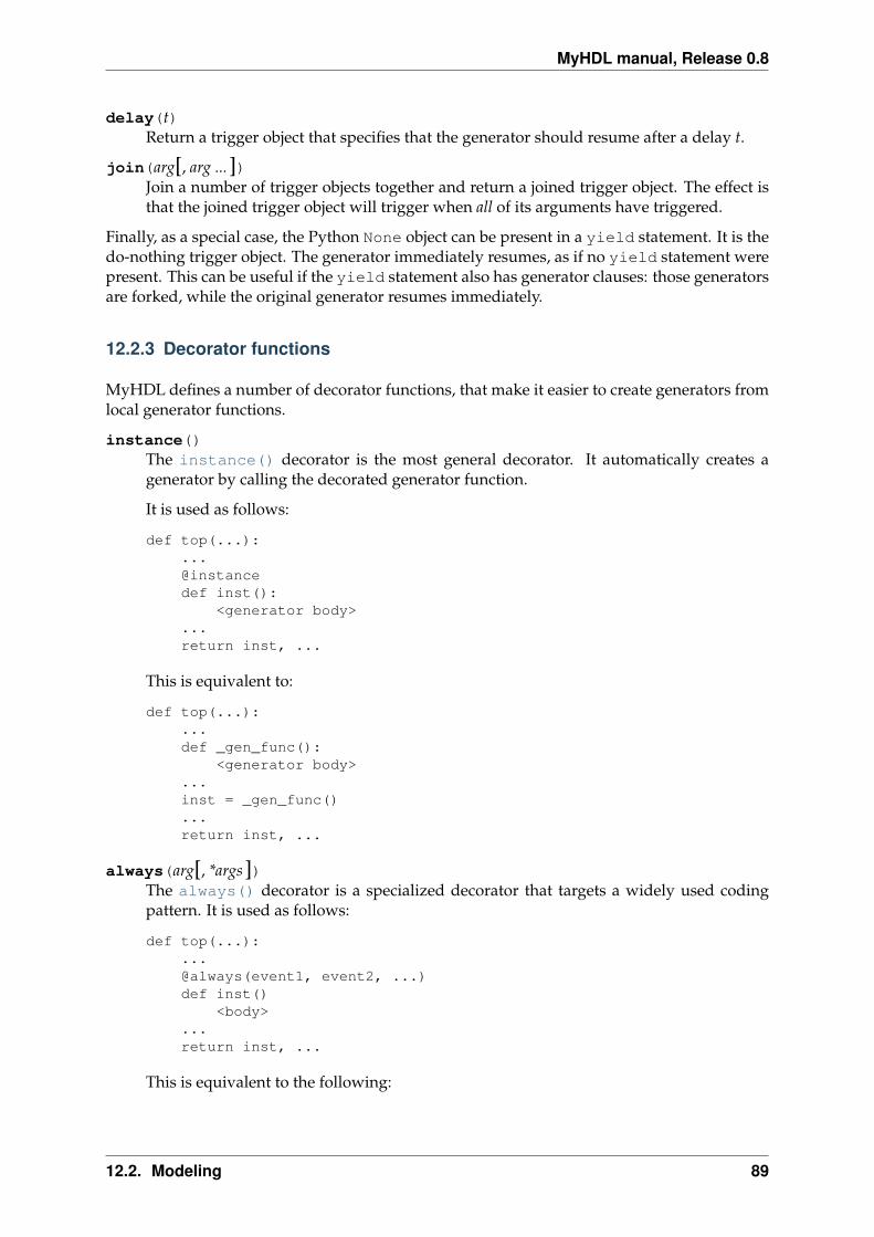
MyHDL manual, Release 0.8
delay(t)Return a trigger object that specifies that the generator should resume after a delay t.
join(arg[, arg ...])Join a number of trigger objects together and return a joined trigger object. The effect isthat the joined trigger object will trigger when all of its arguments have triggered.
Finally, as a special case, the Python None object can be present in a yield statement. It is thedo-nothing trigger object. The generator immediately resumes, as if no yield statement werepresent. This can be useful if the yield statement also has generator clauses: those generatorsare forked, while the original generator resumes immediately.
12.2.3 Decorator functions
MyHDL defines a number of decorator functions, that make it easier to create generators fromlocal generator functions.
instance()The instance() decorator is the most general decorator. It automatically creates agenerator by calling the decorated generator function.
It is used as follows:
def top(...):...@instancedef inst():
<generator body>...return inst, ...
This is equivalent to:
def top(...):...def _gen_func():
<generator body>...inst = _gen_func()...return inst, ...
always(arg[, *args])The always() decorator is a specialized decorator that targets a widely used codingpattern. It is used as follows:
def top(...):...@always(event1, event2, ...)def inst()
<body>...return inst, ...
This is equivalent to the following:
12.2. Modeling 89

MyHDL manual, Release 0.8
def top(...):...def _func():
<body>
def _gen_func()while True:
yield event1, event2, ..._func()
...inst = _gen_func()...return inst, ...
The argument list of the decorator corresponds to the sensitivity list. Only signals, edgespecifiers, or delay objects are allowed. The decorated function should be a classic func-tion.
always_comb()The always_comb() decorator is used to describe combinatorial logic.
def top(...):...@always_combdef comb_inst():
<combinatorial body>...return comb_inst, ...
The always_comb() decorator infers the inputs of the combinatorial logic and the cor-responding sensitivity list automatically. The decorated function should be a classic func-tion.
always_seq(edge, reset)The always_seq() decorator is used to describe sequential (clocked) logic.
The edge parameter should be a clock edge (clock.posedge or clock.negedge). Thereset parameter should a ResetSignal object.
12.2.4 MyHDL data types
MyHDL defines a number of data types that are useful for hardware description.
The intbv class
class intbv([val=0] [, min=None] [, max=None])This class represents int-like objects with some additional features that make it suitablefor hardware design.
The val argument can be an int, a long, an intbv or a bit string (a string with only ‘0’sor ‘1’s). For a bit string argument, the value is calculated as in int(bitstring, 2).The optional min and max arguments can be used to specify the minimum and maximumvalue of the intbv object. As in standard Python practice for ranges, the minimum valueis inclusive and the maximum value is exclusive.
90 Chapter 12. Reference

MyHDL manual, Release 0.8
The minimum and maximum values of an intbv object are available as attributes:
minRead-only attribute that is the minimum value (inclusive) of an intbv, or None forno minimum.
maxRead-only attribute that is the maximum value (exclusive) of an intbv, or None forno maximum.
signed()Interpretes the msb bit as as sign bit and extends it into the higher-order bits of theunderlying object value. The msb bit is the highest-order bit within the object’s bitwidth.
Return type integer
Unlike int objects, intbv objects are mutable; this is also the reason for their existence. Muta-bility is needed to support assignment to indexes and slices, as is common in hardware design.For the same reason, intbv is not a subclass from int, even though int provides most of thedesired functionality. (It is not possible to derive a mutable subtype from an immutable basetype.)
An intbv object supports the same comparison, numeric, bitwise, logical, and conversionoperations as int objects. See http://www.python.org/doc/current/lib/typesnumeric.htmlfor more information on such operations. In all binary operations, intbv objects can worktogether with int objects. For mixed-type numeric operations, the result type is an int or along. For mixed-type bitwise operations, the result type is an intbv.
In addition, intbv supports a number of sequence operators. In particular, the len() func-tion returns the object’s bit width. Furthermore, intbv objects support indexing and slicingoperations:
Operation Result Notesbv[i] item i of bv (1)bv[i] = x item i of bv is replaced by x (1)bv[i:j] slice of bv from i downto j (2)(3)bv[i:j] = t slice of bv from i downto j is replaced by t (2)(4)
1. Indexing follows the most common hardware design conventions: the lsb bit is the right-most bit, and it has index 0. This has the following desirable property: if the intbvvalue is decomposed as a sum of powers of 2, the bit with index i corresponds to theterm 2**i.
2. In contrast to standard Python sequencing conventions, slicing range are downward.This is a consequence of the indexing convention, combined with the common conven-tion that the most significant digits of a number are the leftmost ones. The Python con-vention of half-open ranges is followed: the bit with the highest index is not included.However, it is the leftmost bit in this case. As in standard Python, this takes care of one-off issues in many practical cases: in particular, bv[i:] returns i bits; bv[i:j] has i-jbits. When the low index j is omitted, it defaults to 0. When the high index i is omitted,it means “all” higher order bits.
3. The object returned from a slicing access operation is always a positive intbv; higherorder bits are implicitly assumed to be zero. The bit width is implicitly stored in the
12.2. Modeling 91
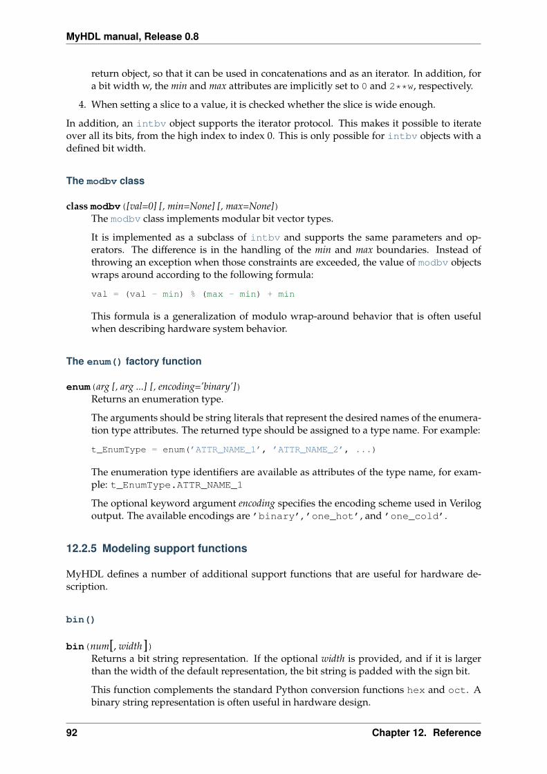
MyHDL manual, Release 0.8
return object, so that it can be used in concatenations and as an iterator. In addition, fora bit width w, the min and max attributes are implicitly set to 0 and 2**w, respectively.
4. When setting a slice to a value, it is checked whether the slice is wide enough.
In addition, an intbv object supports the iterator protocol. This makes it possible to iterateover all its bits, from the high index to index 0. This is only possible for intbv objects with adefined bit width.
The modbv class
class modbv([val=0] [, min=None] [, max=None])The modbv class implements modular bit vector types.
It is implemented as a subclass of intbv and supports the same parameters and op-erators. The difference is in the handling of the min and max boundaries. Instead ofthrowing an exception when those constraints are exceeded, the value of modbv objectswraps around according to the following formula:
val = (val - min) % (max - min) + min
This formula is a generalization of modulo wrap-around behavior that is often usefulwhen describing hardware system behavior.
The enum() factory function
enum(arg [, arg ...] [, encoding=’binary’])Returns an enumeration type.
The arguments should be string literals that represent the desired names of the enumera-tion type attributes. The returned type should be assigned to a type name. For example:
t_EnumType = enum(’ATTR_NAME_1’, ’ATTR_NAME_2’, ...)
The enumeration type identifiers are available as attributes of the type name, for exam-ple: t_EnumType.ATTR_NAME_1
The optional keyword argument encoding specifies the encoding scheme used in Verilogoutput. The available encodings are ’binary’, ’one_hot’, and ’one_cold’.
12.2.5 Modeling support functions
MyHDL defines a number of additional support functions that are useful for hardware de-scription.
bin()
bin(num[, width])Returns a bit string representation. If the optional width is provided, and if it is largerthan the width of the default representation, the bit string is padded with the sign bit.
This function complements the standard Python conversion functions hex and oct. Abinary string representation is often useful in hardware design.
92 Chapter 12. Reference
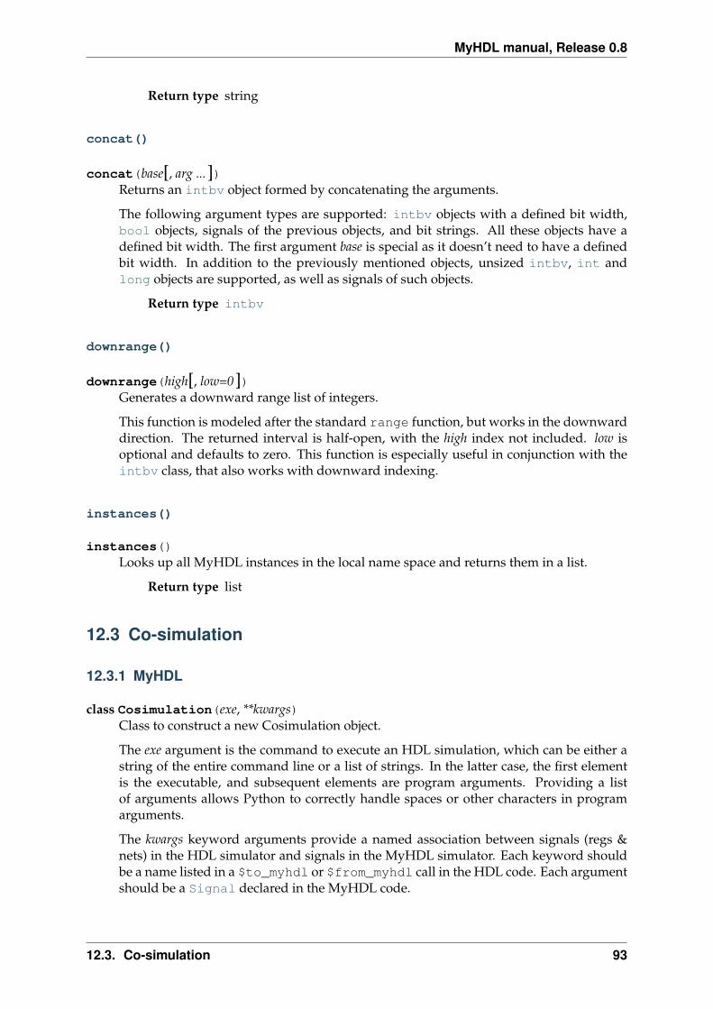
MyHDL manual, Release 0.8
Return type string
concat()
concat(base[, arg ...])Returns an intbv object formed by concatenating the arguments.
The following argument types are supported: intbv objects with a defined bit width,bool objects, signals of the previous objects, and bit strings. All these objects have adefined bit width. The first argument base is special as it doesn’t need to have a definedbit width. In addition to the previously mentioned objects, unsized intbv, int andlong objects are supported, as well as signals of such objects.
Return type intbv
downrange()
downrange(high[, low=0])Generates a downward range list of integers.
This function is modeled after the standard range function, but works in the downwarddirection. The returned interval is half-open, with the high index not included. low isoptional and defaults to zero. This function is especially useful in conjunction with theintbv class, that also works with downward indexing.
instances()
instances()Looks up all MyHDL instances in the local name space and returns them in a list.
Return type list
12.3 Co-simulation
12.3.1 MyHDL
class Cosimulation(exe, **kwargs)Class to construct a new Cosimulation object.
The exe argument is the command to execute an HDL simulation, which can be either astring of the entire command line or a list of strings. In the latter case, the first elementis the executable, and subsequent elements are program arguments. Providing a listof arguments allows Python to correctly handle spaces or other characters in programarguments.
The kwargs keyword arguments provide a named association between signals (regs &nets) in the HDL simulator and signals in the MyHDL simulator. Each keyword shouldbe a name listed in a $to_myhdl or $from_myhdl call in the HDL code. Each argumentshould be a Signal declared in the MyHDL code.
12.3. Co-simulation 93

MyHDL manual, Release 0.8
12.3.2 Verilog
$to_myhdl(arg, [, arg ...])Task that defines which signals (regs & nets) should be read by the MyHDL simulator.This task should be called at the start of the simulation.
$from_myhdl(arg, [, arg ...])Task that defines which signals should be driven by the MyHDL simulator. In Verilog,only regs can be specified. This task should be called at the start of the simulation.
12.4 Conversion to Verilog and VHDL
12.4.1 Conversion
toVerilog(func [, *args] [, **kwargs])
Converts a MyHDL design instance to equivalent Verilog code, and also gen-erates a test bench to verify it. func is a function that returns an instance.toVerilog() calls func under its control and passes *args and **kwargs to thecall.
The return value is the same as would be returned by the call func(*args,**kwargs). It should be assigned to an instance name.
The top-level instance name and the basename of the Verilog output filenameis func.func_name by default.
For more information about the restrictions on convertible MyHDL code, seesection The convertible subset in Chapter Conversion to Verilog and VHDL.
toVerilog() has the following attribute:
nameThis attribute is used to overwrite the default top-level instance name and the base-name of the Verilog output filename.
directoryThis attribute is used to set the directory to which converted verilog files are written.By default, the current working directory is used.
timescaleThis attribute is used to set the timescale in Verilog format. The assigned valueshould be a string. The default timescale is “1ns/10ps”.
toVHDL(func[, *args][, **kwargs])Converts a MyHDL design instance to equivalent VHDL code. func is a function thatreturns an instance. toVHDL() calls func under its control and passes *args and **kwargsto the call.
The return value is the same as would be returned by the call func(*args,
**kwargs). It can be assigned to an instance name. The top-level instance name andthe basename of the Verilog output filename is func.func_name by default.
toVHDL() has the following attributes:
94 Chapter 12. Reference

MyHDL manual, Release 0.8
nameThis attribute is used to overwrite the default top-level instance name and the base-name of the VHDL output.
directoryThis attribute is used to set the directory to which converted VHDL files are written.By default, the current working directory is used.
component_declarationsThis attribute can be used to add component declarations to the VHDL output.When a string is assigned to it, it will be copied to the appropriate place in theoutput file.
libraryThis attribute can be used to set the library in the VHDL output file. The assignedvalue should be a string. The default library is work.
12.4.2 User-defined Verilog and VHDL code
User-defined code can be inserted in the Verilog or VHDL output through the use of functionattributes. Suppose a function <func>() defines a hardware module. User-defined code canbe specified for the function with the following function attributes:
<func>.vhdl_codeA template string for user-defined code in the VHDL output.
<func>.verilog_codeA template string for user-defined code in the Verilog output.
When such a function attribute is defined, the normal conversion process is bypassed and theuser-defined code is inserted instead. The template strings should be suitable for the standardstring.Template constructor. They can contain interpolation variables (indicated by a $prefix) for all signals in the context. Note that the function attribute can be defined anywherewhere <func>() is visible, either outside or inside the function itself.
These function attributes cannot be used with generator functions or decorated local functions,as these are not elaborated before simulation or conversion. In other words, they can only beused with functions that define structure.
12.5 Conversion output verification
MyHDL provides an interface to verify converted designs. This is used extensively in thepackage itself to verify the conversion functionality. This capability is exported by the packageso that users can use it also.
12.5.1 Verification interface
All functions related to conversion verification are implemented in the myhdl.conversionpackage.
verify(func[, *args][, **kwargs])Used like toVHDL() and toVerilog(). It converts MyHDL code, simulates both the
12.5. Conversion output verification 95
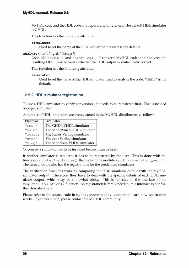
MyHDL manual, Release 0.8
MyHDL code and the HDL code and reports any differences. The default HDL simulatoris GHDL.
This function has the following attribute:
simulatorUsed to set the name of the HDL simulator. "GHDL" is the default.
analyze(func[, *args][, **kwargs])Used like toVHDL() and toVerilog(). It converts MyHDL code, and analyzes theresulting HDL. Used to verify whether the HDL output is syntactically correct.
This function has the following attribute:
simulatorUsed to set the name of the HDL simulator used to analyze the code. "GHDL" is thedefault.
12.5.2 HDL simulator registration
To use a HDL simulator to verify conversions, it needs to be registered first. This is neededonce per simulator.
A number of HDL simulators are preregistered in the MyHDL distribution, as follows:
Identifier Simulator"GHDL" The GHDL VHDL simulator"vsim" The ModelSim VHDL simulator"icarus" The Icarus Verilog simulator"cver" The cver Verilog simulator"vlog" The Modelsim VHDL simulator
Of course, a simulator has to be installed before it can be used.
If another simulator is required, it has to be registered by the user. This is done with thefunction registerSimulation() that lives in the module myhdl.conversion._verify.The same module also has the registrations for the predefined simulators.
The verification functions work by comparing the HDL simulator output with the MyHDLsimulator output. Therefore, they have to deal with the specific details of each HDL sim-ulator output, which may be somewhat tricky. This is reflected in the interface of theregisterSimulation() function. As registration is rarely needed, this interface is not fur-ther described here.
Please refer to the source code in myhdl.conversion._verify to learn how registrationworks. If you need help, please contact the MyHDL community.
96 Chapter 12. Reference
Python Module Index
mmyhdl, 84myhdl.conversion, 95
97
MyHDL manual, Release 0.8
98 Python Module Index

Index
Symbols_SliceSignal (class in myhdl), 87__call__() (Signal method), 87
Aalways() (in module myhdl), 89always_comb() (in module myhdl), 90always_seq() (in module myhdl), 90analyze() (in module myhdl.conversion), 96
Bbin() (in module myhdl), 92bit indexing, 15bit slicing, 16bus-functional procedure, 33
Ccombinatorial logic, 15, 25component_declarations (in module myhdl),
95concat()
example usage, 16concat() (in module myhdl), 93ConcatSignal (class in myhdl), 88conditional instantiation, 21Cosimulation (class in myhdl), 93
Ddecorator
always, 7always_comb, 15instance, 10
decoratorsabout, 4
delay() (in module myhdl), 88directory (in module myhdl), 94, 95downrange() (in module myhdl), 93driven (Signal attribute), 87driver() (TristateSignal method), 88
Eenum()
example usage, 29enum() (in module myhdl), 92extreme programming, 43
Ggenerators
tutorial on, 3
Iinstance
defined, 10in Python versus hardware design, 11
instance() (in module myhdl), 89instances() (in module myhdl), 93intbv
basic usage, 13bit width, 13conversion, 59, 63intbv.signed, 18max, 13min, 13
intbv (class in myhdl), 90
Jjoin() (in module myhdl), 89
Llibrary (in module myhdl), 95lists of instances and signals, 22
Mmax (intbv attribute), 91max (Signal attribute), 87min (intbv attribute), 91min (Signal attribute), 87modbv (class in myhdl), 92modeling
Finite State Machine, 29
99

MyHDL manual, Release 0.8
high level, 33memories, 38object oriented, 41RTL style, 25structural, 21
modulein Python versus hardware design, 11
myhdl (module), 84myhdl.conversion (module), 95
Nname (in module myhdl), 86, 94negedge (Signal attribute), 86next (Signal attribute), 86now() (in module myhdl), 85
Pposedge (Signal attribute), 86
Rread (Signal attribute), 87ResetSignal (class in myhdl), 87run() (Simulation method), 85
Ssensitivity list, 4, 34, 88sequential logic, 27Signal (class in myhdl), 86SignalType (class in myhdl), 86signed() (intbv method), 91Simulation (class in myhdl), 85simulator (in module myhdl.conversion), 96StopSimulation, 85
Ttimescale (in module myhdl), 86, 94toVerilog() (in module myhdl), 94toVHDL() (in module myhdl), 94traceSignals() (in module myhdl), 85TristateSignal (class in myhdl), 88
Uuser-defined code
description, 64example, 82
Vval (Signal attribute), 86verify() (in module myhdl.conversion), 95Verilog
always block, 4non-blocking assignment, 9
VHDLprocess, 4signal assignment, 9
Wwait
for a rising edge, 9for a signal value change, 15for the completion of a generator, 34
waveform viewing, 30
100 Index