mystic user manual - microwave system calculator · mystic user manual – rev.0.6 3. 2.7.1 about...
TRANSCRIPT

Mystic User Manual

Microwave System Calculator User Manual© 2006-2015 M.TostiAll rights reserved.
Products that are referred to in this document may be either trademarks and/or registered trademarks of the respectiveowners. The publisher and the author make no claim to these trademarks.While every precaution has been taken in the preparation of this document, the publisher and the author assume noresponsibility for errors or omissions, or for damages resulting from the use of information contained in this document orfrom the use of programs and source code that may accompany it. In no event shall the publisher and the author beliable for any loss of profit or any other commercial damage caused or alleged to have been caused directly or indirectlyby this document.
Table of Contents
1 Getting Started...........................................................................4• 1.1 Overview...................................................................................................................4• 1.2 Getting started with Mystic.......................................................................................4• 1.3 Getting started with input data files..........................................................................6• 1.4 Getting started with output result analysis................................................................7• 1.5 Getting started with stage characterization..............................................................9
1.5.1 Amplifier................................................................................................................91.5.2 Attenuator.............................................................................................................91.5.3 Filter......................................................................................................................91.5.4 Loss....................................................................................................................101.5.5 Mixer...................................................................................................................10
2 Menu commands......................................................................11• 2.1 File Menu................................................................................................................11
2.1.1 New.....................................................................................................................112.1.2 Open...................................................................................................................112.1.3 Save....................................................................................................................112.1.4 Quit.....................................................................................................................11
• 2.2 EditInput Menu........................................................................................................112.2.1 Edit Cell...............................................................................................................112.2.2 Insert Row...........................................................................................................112.2.3 Delete Row.........................................................................................................112.2.4 Select All.............................................................................................................112.2.5 Select Row..........................................................................................................112.2.6 Select Column....................................................................................................122.2.7 Deselect All.........................................................................................................122.2.8 Cut to clipboard..................................................................................................122.2.9 Copy to clipboard...............................................................................................122.2.10 Paste from clipboard........................................................................................122.2.11 Delete................................................................................................................12
• 2.3 EditOutput Menu.....................................................................................................122.3.1 Select All.............................................................................................................122.3.2 Deselect All.........................................................................................................122.3.3 Copy to clipboard...............................................................................................12
• 2.4 OpenS2P Menu......................................................................................................132.4.1 ViewS2Pfile........................................................................................................13
• 2.5 RUN Menu..............................................................................................................132.5.1 Run Mystic..........................................................................................................13
• 2.6 Options Menu.........................................................................................................132.6.1 Preferences........................................................................................................132.6.2 Input editable......................................................................................................132.6.3 Enable graphical output......................................................................................132.6.4 Enable working point check................................................................................132.6.5 Enable Visual linearity check..............................................................................13
• 2.7 Help Menu..............................................................................................................14
Mystic User Manual – rev.0.6 3
2.7.1 About Mystic.......................................................................................................14
3 Quick How-to............................................................................15• 3.1 How to input a data file...........................................................................................15• 3.2 How to deal with compression and saturation points.............................................17• 3.3 How to deal with S2P files......................................................................................18• 3.4 Details on visual linearity check.............................................................................20• 3.5 How to save output data.........................................................................................20
3.5.1 Save output tables..............................................................................................213.5.2 Export output pictures........................................................................................21
• 3.6 How to print.............................................................................................................21
4 Mystic versions and license details.......................................22• 4.1 Mystic CL (Command Line version).......................................................................22• 4.2 Mystic Lite...............................................................................................................22• 4.3 Mystic Pro...............................................................................................................22• 4.4 Disclaimer of Warranty...........................................................................................23
5 Technical support....................................................................24• 5.1 Bug reporting..........................................................................................................24• 5.2 Updating to Mystic PRO.........................................................................................24• 5.3 Contact Information................................................................................................24
Mystic User Manual – rev.0.6 4
Illustration IndexFigure 1: Mystic main window................................................................................................5Figure 2: Mystic output displayed by dPlot............................................................................6Figure 3: NF resulting from data.txt example PCB stage at 5 dB gain..................................8Figure 4: NF resulting from data.txt example PCB stage at 8 dB gain..................................9Figure 5: Amplifier in Mystic.................................................................................................16Figure 6: Mystic compression and saturation modeling [dBm both axis]............................17Figure 7: Mystic working point check on active components..............................................18Figure 8: Mystic s2p file scattering parameters visualization..............................................19Figure 9: Mystic visual linearity check on “by stage” output table.......................................20
Index of TablesTable 1: Generic datasheet electrical specifications............................................................15Table 2: Typical performance datasheet electrical measurements......................................16Table 3: Distortion formatting definition................................................................................20
Mystic User Manual – rev.0.6 5
1 Getting Started
1.1 Overview
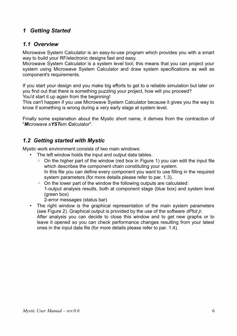
Microwave System Calculator is an easy-to-use program which provides you with a smartway to build your RF/electronic designs fast and easy.Microwave System Calculator is a system level tool; this means that you can project yoursystem using Microwave System Calculator and draw system specifications as well ascomponent's requirements.
If you start your design and you make big efforts to get to a reliable simulation but later onyou find out that there is something puzzling your project, how will you proceed? You'd start it up again from the beginning! This can't happen if you use Microwave System Calculator because it gives you the way toknow if something is wrong during a very early stage at system level.
Finally some explanation about the Mystic short name, it derives from the contraction of"Microwave sYSTem Calculator".
1.2 Getting started with Mystic
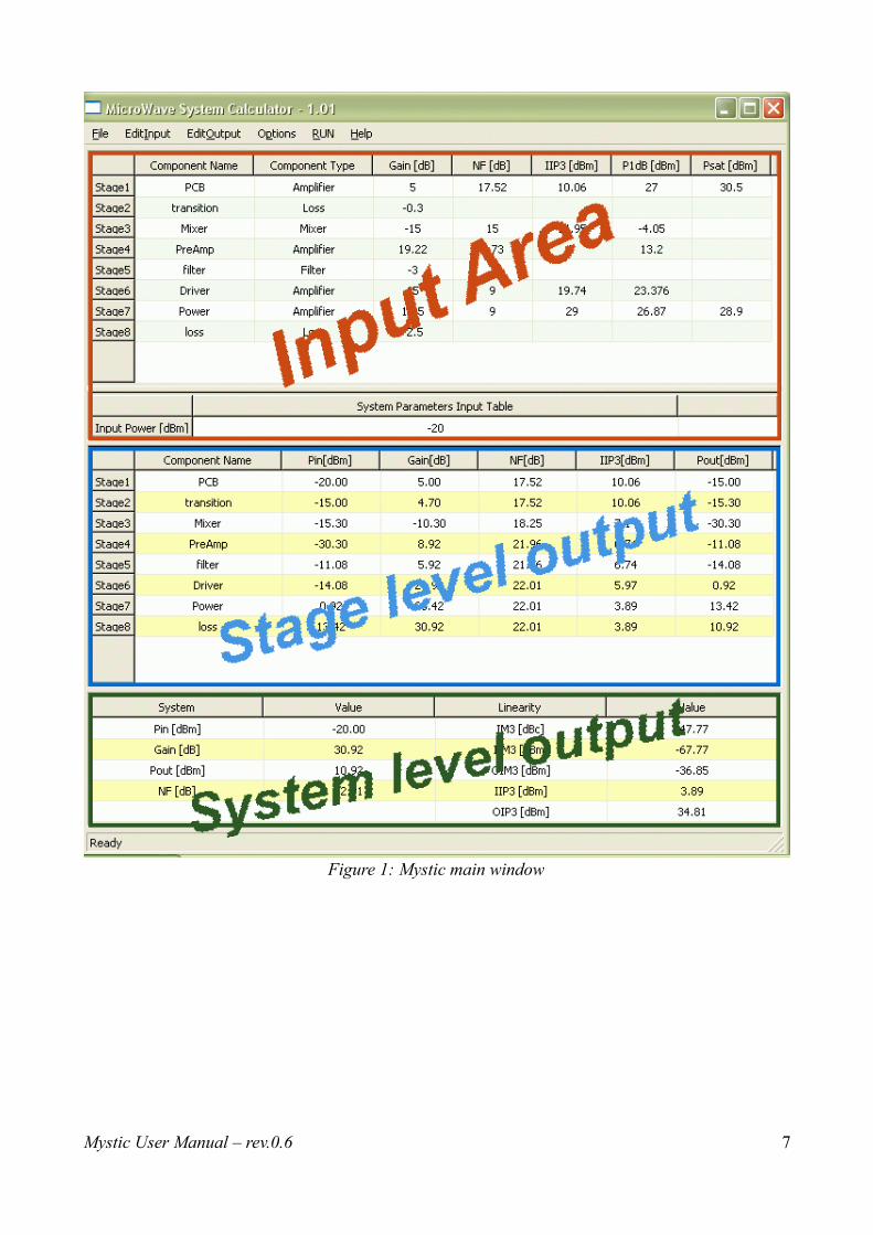
Mystic work environment consists of two main windows:• The left window holds the input and output data tables.
◦ On the higher part of the window (red box in Figure 1) you can edit the input filewhich describes the component chain constituting your system.In this file you can define every component you want to use filling in the requiredsystem parameters (for more details please refer to par. 1.3).
◦ On the lower part of the window the following outputs are calculated:1-output analysis results, both at component stage (blue box) and system level(green box)2-error messages (status bar)
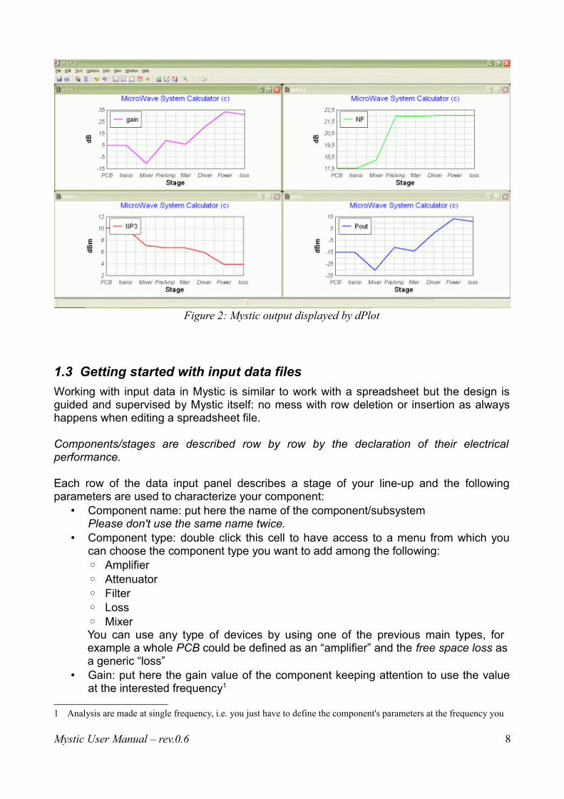
• The right window is the graphical representation of the main system parameters(see Figure 2). Graphical output is provided by the use of the software dPlot jr. After analysis you can decide to close this window and to get new graphs or toleave it opened so you can check performance changes resulting from your latestones in the input data file (for more details please refer to par. 1.4).
Mystic User Manual – rev.0.6 6
Mystic User Manual – rev.0.6 7
Figure 1: Mystic main window
1.3 Getting started with input data files
Working with input data in Mystic is similar to work with a spreadsheet but the design isguided and supervised by Mystic itself: no mess with row deletion or insertion as alwayshappens when editing a spreadsheet file.
Components/stages are described row by row by the declaration of their electricalperformance.
Each row of the data input panel describes a stage of your line-up and the followingparameters are used to characterize your component:
• Component name: put here the name of the component/subsystemPlease don't use the same name twice.
• Component type: double click this cell to have access to a menu from which youcan choose the component type you want to add among the following:◦ Amplifier◦ Attenuator◦ Filter◦ Loss◦ MixerYou can use any type of devices by using one of the previous main types, for example a whole PCB could be defined as an “amplifier” and the free space loss as a generic “loss”
• Gain: put here the gain value of the component keeping attention to use the valueat the interested frequency1
1 Analysis are made at single frequency, i.e. you just have to define the component's parameters at the frequency you
Mystic User Manual – rev.0.6 8
Figure 2: Mystic output displayed by dPlot

• Noise Figure: put here the NF value of the related component keeping attention touse the value at the interested frequency
• IIP3: put here the IIP3 value of the related component keeping attention to use thevalue at the interested frequency. By the way, IIP3=OIP3 - gain
• P1dB: put here the P1dB value of the related component• Psat: put here the Psat value of the related component
Of course Mystic editor allows you to define your components or subsystems in a verydriven way asking you only those parameters required for the component type you haveselected.
In the installation path, and opened by default by Mystic, there is the file “data.txt”. It is agood example to start from and provides you with a generic transmitter design.
Data files are provided as .txt file not encoded or binary written.
This is done to support the smart editing/browsing of the project by the user (for exampleyou don't need to open Mystic only to know what's inside your data files). Anyway YOU'RE STRONGLY SUGGESTED NOT EDITING your data files MANUALLY(even if it is possible paying attention to blind characters).
Please note that it's not possible to use the same component/stage name twice.
1.4 Getting started with output result analysis
Mystic output is provided in 3 different ways:• output table at stage level (see blue box in Figure 1)• output table at system level (see green box in Figure 1)• output plots related to main output quantities (see Figure 2)
At stage level, components/stages are analyzed row by row and the calculation of theirelectrical performance is provided. In particular, each row of this data output panel (bluebox) describes a stage of your line-up by the following electrical parameters:
• Pin: input power to the current component/stage. This is especially useful to checkwhen component's linearity must be guaranteed
• Gain: cumulative gain up to the current component/stage• Noise Figure: cumulative NF up to the current component/stage• Input IP3: cumulative IIP3 up to the current component/stage• Pout: output power of the current component/stage
At system level, the following parameters, related to the whole system, are provided:• Pin: input power to the whole system (user input)• Gain: whole system gain• Pout: whole system output power• Noise Figure: whole system NF• IM3: whole system IM3 calculated both at the input and at the output; IM3 product
are interested to; have a look at component data sheet for help. Use of s2p files as data input for component/stage definition is under development allowing in future Mystic version analysis over frequency.
Mystic User Manual – rev.0.6 9
relative to the power signal level (dB below carrier) is provided too• IP3: whole system IP3 calculated both at the input and the output
At stage level by plots, electrical performance calculated at stage level are plotted.Observation of the impact of the different component/stage on the overall performance isenabled.
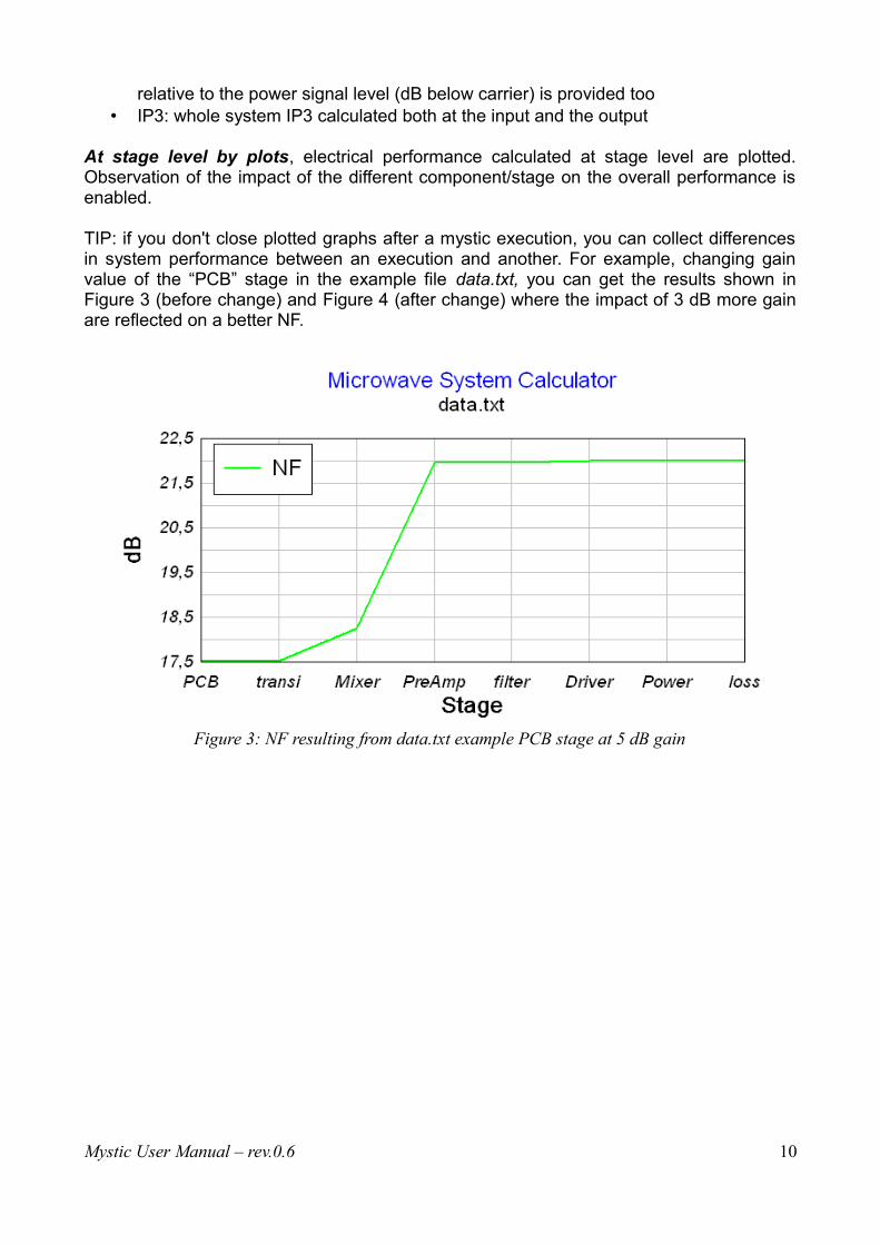
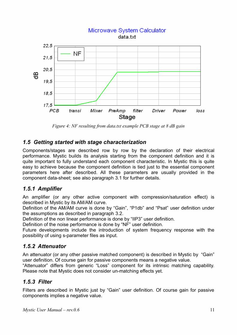
TIP: if you don't close plotted graphs after a mystic execution, you can collect differencesin system performance between an execution and another. For example, changing gainvalue of the “PCB” stage in the example file data.txt, you can get the results shown inFigure 3 (before change) and Figure 4 (after change) where the impact of 3 dB more gainare reflected on a better NF.
Mystic User Manual – rev.0.6 10
Figure 3: NF resulting from data.txt example PCB stage at 5 dB gain
1.5 Getting started with stage characterization
Components/stages are described row by row by the declaration of their electricalperformance. Mystic builds its analysis starting from the component definition and it isquite important to fully understand each component characteristic. In Mystic this is quiteeasy to achieve because the component definition is tied just to the essential componentparameters here after described. All these parameters are usually provided in thecomponent data-sheet; see also paragraph 3.1 for further details.
1.5.1 Amplifier
An amplifier (or any other active component with compression/saturation effect) isdescribed in Mystic by its AM/AM curve. Definition of the AM/AM curve is done by “Gain”, “P1db” and “Psat” user definition underthe assumptions as described in paragraph 3.2.Definition of the non linear performance is done by “IIP3” user definition.Definition of the noise performance is done by “NF” user definition.Future developments include the introduction of system frequency response with thepossibility of using s-parameter files as input.
1.5.2 Attenuator
An attenuator (or any other passive matched component) is described in Mystic by “Gain”user definition. Of course gain for passive components means a negative value.“Attenuator” differs from generic “Loss” component for its intrinsic matching capability.Please note that Mystic does not consider un-matching effects yet.
1.5.3 Filter
Filters are described in Mystic just by “Gain” user definition. Of course gain for passivecomponents implies a negative value.
Mystic User Manual – rev.0.6 11
Figure 4: NF resulting from data.txt example PCB stage at 8 dB gain
Future Mystic development includes introduction of system frequency response with thepossibility of using s-parameter files or filter definitions in terms of type (chebyshev,butterworth, etc.), order and frequency.
1.5.4 Loss
A loss component (or any other passive not matched component) is described in Mystic by“Gain” user definition. Of course gain for passive components means a negative value.
1.5.5 Mixer
As for amplifiers, mixers are described in Mystic by “Gain”, “P1db” and “Psat” but this timereferring to the conversion gain.Definition of the non linear performance is done by “IIP3”.Definition of the noise performance is done by “NF”.Future developments include the introduction of system frequency response with thepossibility of using s-parameter files.
Please note that mixer component in mystic is an image rejecting mixer; “not imagerejecting” mixers are an upcoming feature.
Mystic User Manual – rev.0.6 12
2 Menu commands
2.1 File Menu
2.1.1 New
Generates a new clean input/output tableShortcut: CTRL+N
2.1.2 Open...
Prompts for browsing for input data fileShortcut: CTRL+O
2.1.3 Save...
Saves input data to a fileShortcut: CTRL+S
2.1.4 Quit
Quits mystic. If unsaved data are detected a window prompt will ask the user for saving.Shortcut: CTRL+Q
2.2 EditInput Menu
This menu has effect only on the input table.
2.2.1 Edit Cell
Edits selected cell valueShortcut: F2 or double click
2.2.2 Insert Row
Inserts a new row before the selected cellShortcut: Please use Editinput menu
2.2.3 Delete Row
Deletes selected cell rowShortcut: Please use Editinput menu
2.2.4 Select All
Selects the whole input table (for example in order to copy it on a .txt file)Shortcut: CTRL+A (at least one cell must be selected)
2.2.5 Select Row
Selects the row of the selected cellShortcut: -
Mystic User Manual – rev.0.6 13
2.2.6 Select Column
Selects the column of the selected cellShortcut: -
2.2.7 Deselect All
Deselects any selection active in the input tableShortcut: -
2.2.8 Cut to clipboard
Cuts the current selection to clipboardShortcut: CTRL+X (at least one cell must be selected)
2.2.9 Copy to clipboard
Copies the current selection to clipboardShortcut: CTRL+C (at least one cell must be selected)
2.2.10 Paste from clipboard
Pastes clipboard content into current selectionShortcut: CTRL+V (at least one cell must be selected)
2.2.11 Delete
Deletes current selectionShortcut: -
2.3 EditOutput Menu
This menu has effect only on the output tables. In particular the upper part of the menu affects the stage level table and the lower part thesystem level table.
2.3.1 Select All
Selects the whole output table (for example in order to copy it on a .txt file)Shortcut: CTRL+A (at least one cell must be selected)
2.3.2 Deselect All
Deselects any selection in the input tableShortcut: -
2.3.3 Copy to clipboard
Copies the current selection to clipboardShortcut: CTRL+C (please note that if both output tables are selected, only the first one, stage level table, will be copied)
Mystic User Manual – rev.0.6 14
2.4 OpenS2P Menu
2.4.1 ViewS2Pfile
Prompts for browsing for input S2P data fileShortcut: -
2.5 RUN Menu
2.5.1 Run Mystic
Executes Mystic. Calculation is presented in the output tables and graphs are made.Shortcut: CTRL+R
2.6 Options Menu
Current available configuration options are the following:
2.6.1 Preferences
Menu to set the default start-up folder.Shortcut: CTRL+P
2.6.2 Input editable
Enable/disable input table editing. This is useful to protect input data files by incidental typos.Shortcut: -
2.6.3 Enable graphical output
Enables/disables graphical output. This is useful when you want to make quick changes to the data file and check specificoutput parameters without having the graphical system overview to be generated.Shortcut: -
2.6.4 Enable working point check
Enables/disables graphical active component working point check. This is useful to check in which condition active components are working. In particular, youcan check if the working point is in linear, compression or saturation region.Shortcut: -
2.6.5 Enable Visual linearity check
Enables/disables visual linearity check. This is useful to check against linearity along the chain. Output table is formatted in orderto highlight non linear and saturated components.
Mystic User Manual – rev.0.6 15

Shortcut: -
2.7 Help Menu
2.7.1 About Mystic
Shows version information and Mystic loaded version (Lite/Pro).It shows licensing information for Pro registered users.Shortcut: -
Mystic User Manual – rev.0.6 16
3 Quick How-to
3.1 How to input a data file
Input a data file is quite easy in Mystic. It is just a matter to find the right information in thecomponent's data-sheets.
Let's see an example.
Let's suppose we would like to use in our design the Minicircuit GALI5+ (a surface mountmonolithic amplifier). Moreover let's suppose we want our circuit working in the frequency band:fband = 2.3-2.7 GHz
First we collect the data we need to characterize the component in Mystic.So, download the GALI5+ data-sheet from the Minicircuit web site and verify the followinginformation (we just extracted them from there taking 2.5 GHz as reference frequency, i.e.the mid frequency range term):
Parameters Value [~2.5 GHz]
Gain [dB] 16.75
Noise Figure [dB] 3.5
IIP3 [dB] 15.6
P1dB [dBm] 18
Psat [dBm] 29 (extrapolated by max ratings)
Table 1: Generic datasheet electrical specifications
In order to input this component in a data file, follow the next steps:1. Run Mystic by clicking the start menu link2. Click on “File->New”3. Under “Component Name” column, double click on “Component 1” and type the
component's name “Gali5+”4. Under “Component Type” column, double click on “Double click me” and select the
component's type, in this case “Amplifier”. Several fields become editable.5. Fill in all the numbers in Table 1 in the corresponding Mystic cells by double clicking
each cell
Let's add, for example, also a 3 dB loss, follow the next steps:6. Under “Component Name” column, double click on “Component 2” and type the
component's name “loss”7. Under “Component Type” column, double click on “Double click me” and select the
component's type, in this case “Loss”. Gain field becomes editable.8. Fill in the gain field cell with the “-3” value
Let's define the input power to the just defined chain, for example let's consider -20 dBm:9. Fill in “input power” cell, -20
Mystic User Manual – rev.0.6 17
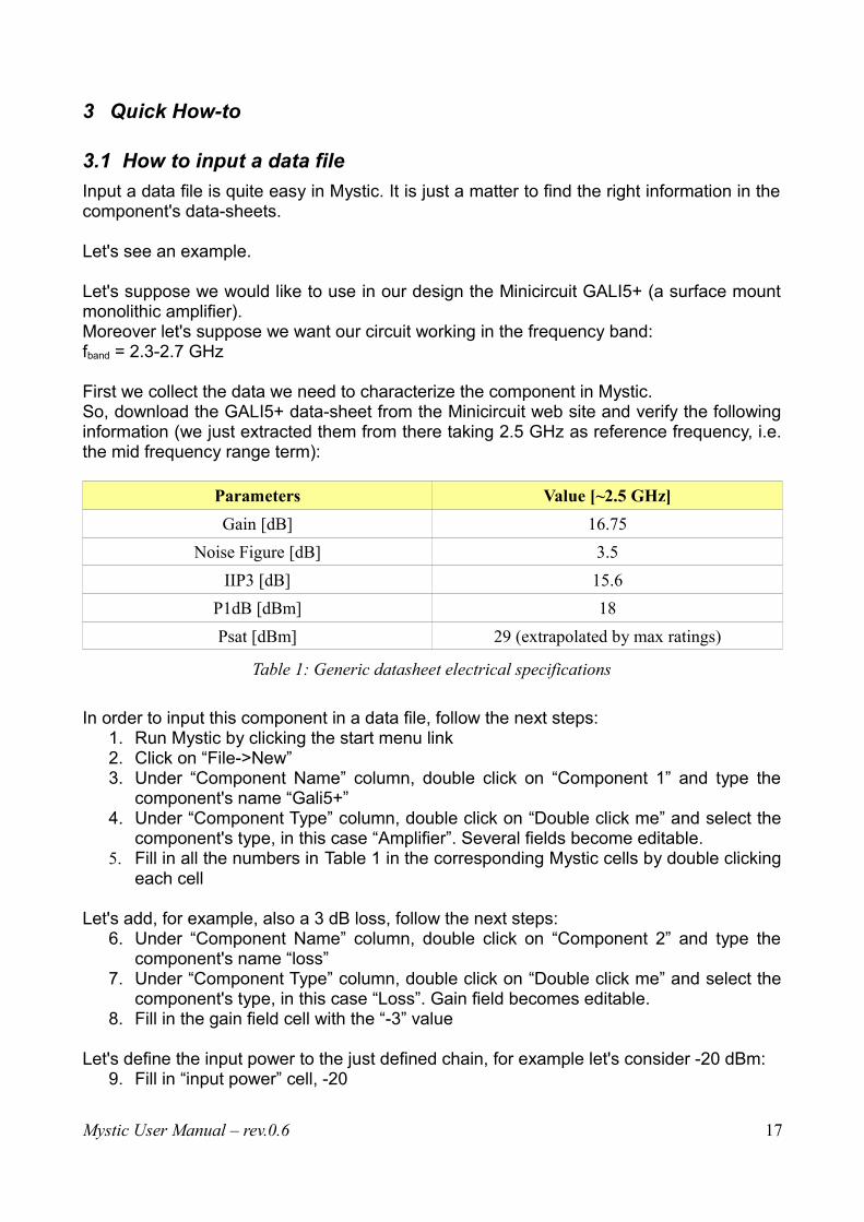
Now, check that your inputs are similar to Figure 5 and click on the “Run” menubutton to see the results of Mystic analysis.
Let's suppose the just done analysis made by Mystic is promising and we want to makeour analysis more precise; in this case we have to provide Mystic with more precisevalues. We have 2 choices:
1. measure the parameters we need on component samples, i.e. characterize it2. collect the data we need asking to the component producer
In case of GALI5+, Minicircuit has already done this for us; just download the GALI5+“Typical Performance Data” pdf file. From that we got data at 3 frequencies, 2.3 GHz, 2.5GHz, 2.7 GHz (Vd=4.45 V).
Parameters Value (2.3/2.5/2.7 [GHz])
Gain [dB] 17.85 / 17.48 / 17.12
Noise Figure [dB] 3.71 / 3.72 / 3.75
IIP3 [dB] 10.88 / 10.57 / 10.28
P1dB [dBm] 15.65 / 15.13 / 14.36
Psat [dBm] 29 (extrapolated by max ratings)
Table 2: Typical performance datasheet electrical measurements
As you can see comparing Table 1 and Table 2, a significant difference is possible: chooseelectrical values carefully.From Table 2 is possible to build three different data files to be analyzed by Mystic one foreach frequency we are interested (lower, mid and higher band point).
Mystic User Manual – rev.0.6 18
Figure 5: Amplifier in Mystic
3.2 How to deal with compression and saturation points
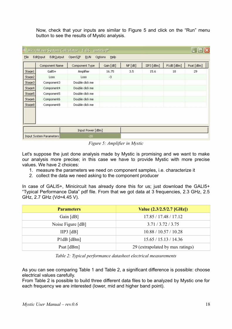
When taking into account active components, Mystic calculates the Pin-Pout characteristiccurve.In particular, Mystic makes the following hypothesis before and after the 1dB compressionpoint:
• pure linearity is assumed 5 dB2 before the input power corresponding to P1dB• output saturation power is fixed 5 dB2 after P1dB (only when Psat is not expressly
defined in Mystic active component Psat field)
Figure 6 shows an example of the Mystic modeling of an active component (see data.txt,PCB component: Gain = 5 dB, P1dB = 27 dBm, Psat = 30.5 dBm). The 1dB compressionat the 1dB compression point is highlighted by the green line.
Figure 6: Mystic compression and saturation modeling [dBm both axis]
Mystic provides you with an effective way to check how your active devices are working.By executing the “working point check” with Mystic (see par. 2.6.4), you get pictures likeFigure 7, one for each active component. The working point is indicated, as well as theP1dB, over the Pin/Pout curve. The user has, this way, a perfect control on linearitybehavior at component's level and consequently at system level.
2 The above 5 dB assumption is widely applicable; in any case configuration of these parameters is an upcoming feature.
Mystic User Manual – rev.0.6 19

Figure 7: Mystic working point check on active components
3.3 How to deal with S2P files
Mystic supports reading s2p files and you can get advantages by this function two ways:• just use Mystic as a reader for s2p files• open s2p file to be able to fill component's gain cell in the description row of the
input Mystic table. S21 scattering parameter graph can be explored in order to getthe right gain value at the required simulation frequency.
Figure 8 shows an example of the Mystic capability in graphing s2p files.
Mystic User Manual – rev.0.6 20
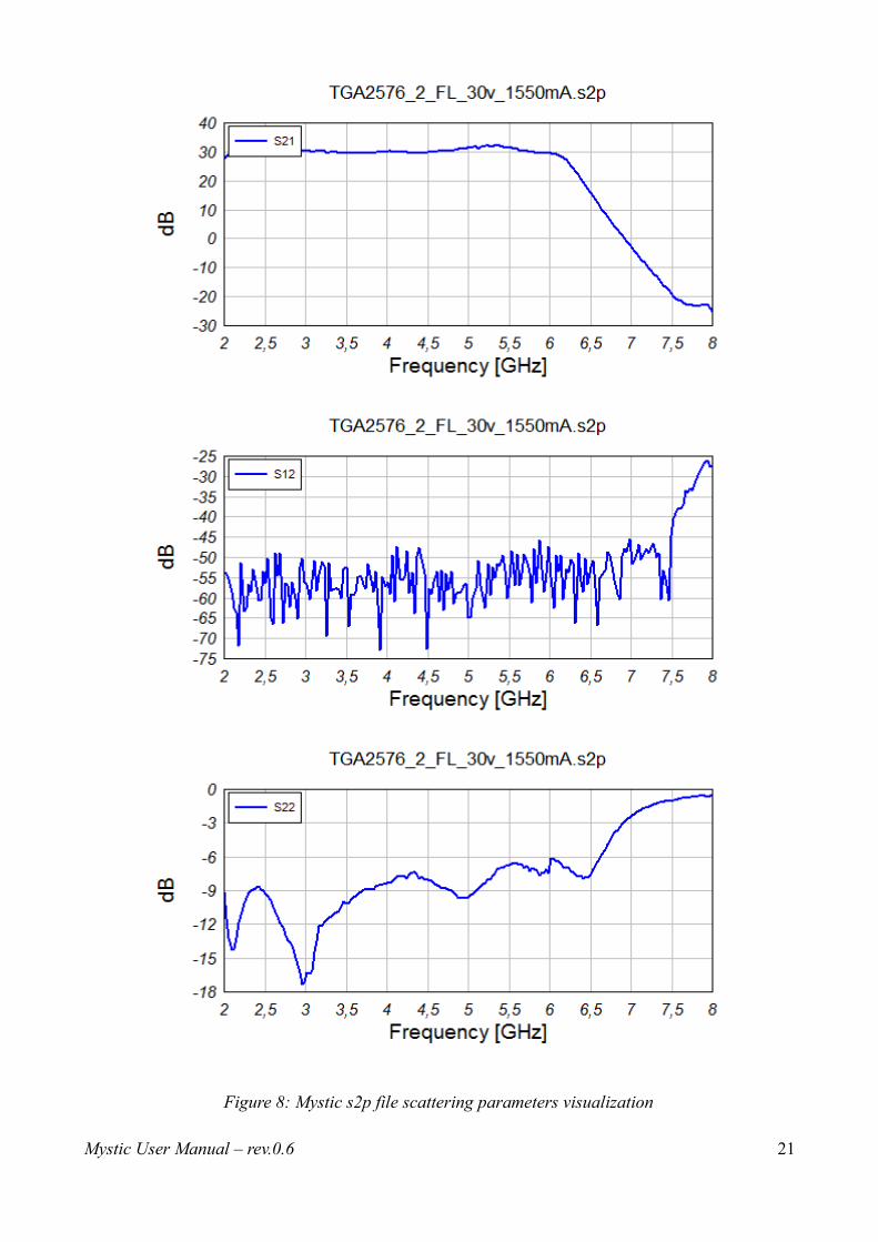
Figure 8: Mystic s2p file scattering parameters visualization
Mystic User Manual – rev.0.6 21
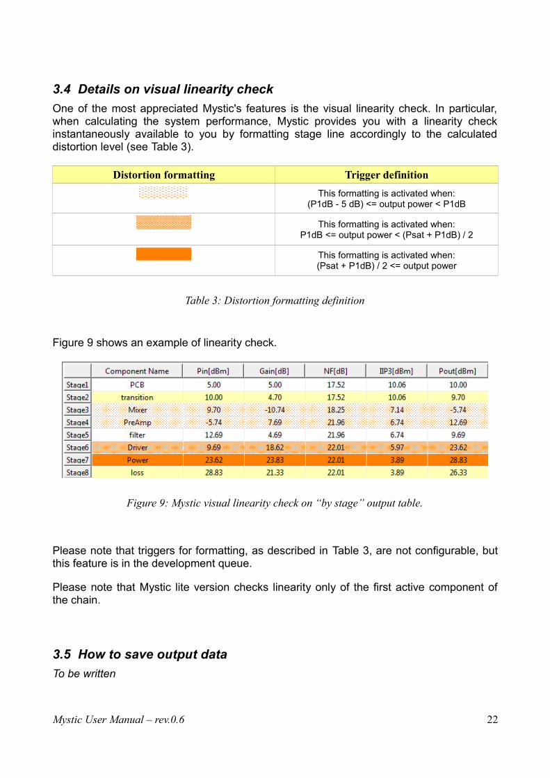
3.4 Details on visual linearity check
One of the most appreciated Mystic's features is the visual linearity check. In particular,when calculating the system performance, Mystic provides you with a linearity checkinstantaneously available to you by formatting stage line accordingly to the calculateddistortion level (see Table 3).
Distortion formatting Trigger definition
This formatting is activated when:(P1dB - 5 dB) <= output power < P1dB
This formatting is activated when:P1dB <= output power < (Psat + P1dB) / 2
This formatting is activated when:(Psat + P1dB) / 2 <= output power
Table 3: Distortion formatting definition
Figure 9 shows an example of linearity check.
Figure 9: Mystic visual linearity check on “by stage” output table.
Please note that triggers for formatting, as described in Table 3, are not configurable, butthis feature is in the development queue.
Please note that Mystic lite version checks linearity only of the first active component ofthe chain.
3.5 How to save output data
To be written
Mystic User Manual – rev.0.6 22

3.5.1 Save output tables
3.5.2 Export output pictures
3.6 How to print
To be written
Mystic User Manual – rev.0.6 23
4 Mystic versions and license details
Please read carefully the following terms and conditions before using this software. Youruse of this software indicates your acceptance of this license agreement and warranty.
Microwave System Calculator CL and Lite version may be freely distributed as long as thedistribution package is not modified. A copy of this Agreement must be included with eachcopy of Microwave System Calculator. Any distributor may not remove or alter anycopyright notices contained within the Program (or archive containing the program).
No person or company may charge a fee for the distribution of Microwave SystemCalculator. If you are aware of any unauthorized third party distributing Microwave SystemCalculator and/or charging a fee for this software, please report such violations to yourconsumer protection authorities.
You may not rent, lease, sell the program to any third party. You may not modify, decompile, emulate, clone, disassemble or reverse engineer theprogram or any subset of the program.Any such unauthorized use shall result in immediate and automatic termination of thislicense and may result in criminal and/or civil prosecution.
You are specifically prohibited from:
• Charging or requesting donations for any copies, however made
• Distributing the software and/or documentation in whole or in part with otherproducts (commercial or otherwise) without prior a written permission
• Distributing or publishing registration key-file or key-generator software designed to circumvent the registration process
4.1 Mystic CL (Command Line version)
Microwave System Calculator CL is freeware, that means that this product may be usedfree of charge by individuals, no profit organizations, commercial organizations andgovernment agencies for non commercial or commercial uses.
Please note that this version of Mystic is discontinued.
4.2 Mystic Lite
Microwave System Calculator Lite is freeware, that means that this product may be usedfree of charge by individuals, no profit organizations, commercial organizations andgovernment agencies for non commercial or commercial uses.
4.3 Mystic Pro
By donating, you will be sent a registration key-file which will unlock additional featuresand remove any software limitations.
Microwave System Calculator PRO version can not be freely distributed.
Mystic User Manual – rev.0.6 24

4.4 Disclaimer of Warranty
Microwave System Calculator is distributed "as is". No warranty of any kind is expressed or implied. The author will not be liable for data loss, damages, loss of profits or any other kind of losswhile using or misusing this software: you use at your own risk.
Mystic User Manual – rev.0.6 25
5 Technical support
5.1 Bug reporting
Before reporting errors, please see the description of known problems and possiblesolutions on Mystic web site and upgrade to the latest Mystic version.
When reporting bugs, please include Mystic version number (select the About commandon the Help menu).
5.2 Updating to Mystic PRO
Updates to the PRO version of Mystic are available by donating using Paypal (see link onMystic home page). Any donation grants you free updates up to 2 years after date ofdonation.
Mystic PRO version is granted freely to universities and students.
5.3 Contact Information
Your comments, suggestions, and questions are always welcome. Please send them to our e-mail address:
Mystic User Manual – rev.0.6

Mystic
Copyright © 2006-2015 M.Tosti
All rights reserved.