mythic 18 - frank's hospital workshop · mythic 18 service manual ref : m18-sm-001 rev 02 ....
TRANSCRIPT

MYTHIC 18 Copyright© Orphée SA. All Rights Reserved. Page 1/68
ORPHEE 19, chemin du champ-des-filles
CH-1228 Geneva / Plan-les-Ouates SWITZERLAND
Tel : +41 (0) 22 706 1840 Fax : +41 (0) 22 794 4391
http://www.orphee-medical.com
MYTHIC 18
SSEERRVVIICCEE MMAANNUUAALL REF : M18-SM-001 Rev 02

REF : M18-SM-001 Rev 02
Page 2/68 Copyright© Orphée SA. All Rights Reserved. MYTHIC 18
REVISIONS
Revision Nb Date Author Software Comments
01 19/07/04 HC V 0.6x Creation 02 28/02/05 HC V 1.0X Update of all parts
CONTACT ADDRESS MANUFACTURER
M C2 Diagnostics 2214, Bd de la Lironde 34397 Montpellier Cedex 5 FRANCE
AUTHORIZED REPRESENTATIVE
WORLDWIDE
ORPHEE SA 19, chemin du champ-des-filles CH-1228 Geneva / Plan-les-Ouates SWITZERLAND Tel : +41 (0) 22 706 1840 Fax : +41 (0) 22 794 4391 http://www.orphee-medical.com
LOCAL REPRESENTATIVE
REF : M18-SM-001 Rev 02
MYTHIC 18 Copyright© Orphée SA. All Rights Reserved. Page 3/68
IMPORTANT SAFETY INSTRUCTIONS
RISK OF DANGER ! Indicates a procedure to be strictly respected in order to avoid any risks for the operator (user) or damages on the instrument or on the quality of results.
Indicates that wearing gloves is mandatory before performing the described operation due to risk of contact with materials that may be infectious.
NOTA : Indicates important additional information.
BEFORE TO INSTALL OR TO MAINTAIN A MYTHIC 18 YOU HAVE TO READ AND TO REFER TO THE USER’S MANUAL. OPERATORS MUST HAVE RECEIVED ADEQUATE TRAINING.
BE CAREFUL WITH THE EDGE OF THE METAL SHEETS AFTER HAVING DISMANTLED THE COVERS.
REF : M18-SM-001 Rev 02
Page 4/68 Copyright© Orphée SA. All Rights Reserved. MYTHIC 18
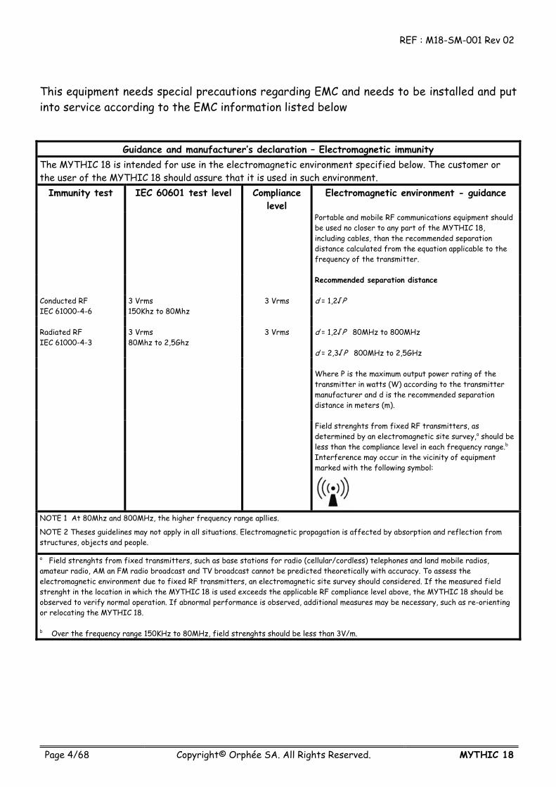
This equipment needs special precautions regarding EMC and needs to be installed and put into service according to the EMC information listed below
Guidance and manufacturer’s declaration – Electromagnetic immunity The MYTHIC 18 is intended for use in the electromagnetic environment specified below. The customer or the user of the MYTHIC 18 should assure that it is used in such environment.
Immunity test IEC 60601 test level Compliance level
Electromagnetic environment - guidance
Portable and mobile RF communications equipment should be used no closer to any part of the MYTHIC 18, including cables, than the recommended separation distance calculated from the equation applicable to the frequency of the transmitter.
Recommended separation distance
Conducted RF IEC 61000-4-6
3 Vrms 150Khz to 80Mhz
3 Vrms d = 1,2√P
Radiated RF IEC 61000-4-3
3 Vrms 80Mhz to 2,5Ghz
3 Vrms d = 1,2√P 80MHz to 800MHz d = 2,3√P 800MHz to 2,5GHz
Where P is the maximum output power rating of the
transmitter in watts (W) according to the transmitter manufacturer and d is the recommended separation distance in meters (m).
Field strenghts from fixed RF transmitters, as
determined by an electromagnetic site survey,a should be less than the compliance level in each frequency range.b
Interference may occur in the vicinity of equipment marked with the following symbol:
NOTE 1 At 80Mhz and 800MHz, the higher frequency range apllies.
NOTE 2 Theses guidelines may not apply in all situations. Electromagnetic propagation is affected by absorption and reflection from structures, objects and people.
a Field strenghts from fixed transmitters, such as base stations for radio (cellular/cordless) telephones and land mobile radios, amateur radio, AM an FM radio broadcast and TV broadcast cannot be predicted theoretically with accuracy. To assess the electromagnetic environment due to fixed RF transmitters, an electromagnetic site survey should considered. If the measured field strenght in the location in which the MYTHIC 18 is used exceeds the applicable RF compliance level above, the MYTHIC 18 should be observed to verify normal operation. If abnormal performance is observed, additional measures may be necessary, such as re-orienting or relocating the MYTHIC 18. b Over the frequency range 150KHz to 80MHz, field strenghts should be less than 3V/m.

REF : M18-SM-001 Rev 02
MYTHIC 18 Copyright© Orphée SA. All Rights Reserved. Page 5/68
REF : M18-SM-001 Rev 02
Page 6/68 Copyright© Orphée SA. All Rights Reserved. MYTHIC 18
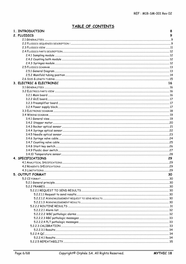
TABLE OF CONTENTS
1. INTRODUCTION 8 2. FLUIDICS 9
2.1 GENERALITIES ......................................................................................................................................................................................9 2.2 FLUIDICS SEQUENCES DESCRIPTION : ................................................................................................................................................9 2.3 FLUIDICS VIEW ...................................................................................................................................................................................11 2.4 FLUIDICS PARTS DESCRIPTION.......................................................................................................................................................... 12
2.4.1 Sampling module ..................................................................................................................................................................... 12 2.4.2 Counting bath module ........................................................................................................................................................... 12 2.4.3 Syringes module..................................................................................................................................................................... 12
2.5 FLUIDICS DIAGRAM............................................................................................................................................................................ 13 2.5.1 General Diagram ..................................................................................................................................................................... 13 2.5.2 Manifold tubing position ...................................................................................................................................................... 14
2.6 SIZE & LENGTH TUBING..................................................................................................................................................................... 15 3. ELECTRIC & ELECTRONIC 16
3.1 GENERALITIES .................................................................................................................................................................................... 16 3.2 ELECTRICS PARTS VIEW ..................................................................................................................................................................... 16
3.2.1 Main board ............................................................................................................................................................................... 16 3.2.2 GUI board................................................................................................................................................................................ 17 3.2.3 Preamplifier board ................................................................................................................................................................ 17 3.2.4 Power supply block................................................................................................................................................................. 17
3.3 ELECTRONIC DIAGRAM ....................................................................................................................................................................... 18 3.4 WIRING DIAGRAM.............................................................................................................................................................................. 19
3.4.1 General view............................................................................................................................................................................. 19 3.4.2 Stepper motor........................................................................................................................................................................20 3.4.3 Rocker optical sensor ........................................................................................................................................................... 21 3.4.4 Syringe optical sensor..........................................................................................................................................................22 3.4.5 Needle optical sensor...........................................................................................................................................................23 3.4.6 Syringe valve cable................................................................................................................................................................24 3.4.7 Counting valve cable..............................................................................................................................................................25 3.4.8 Start key switch....................................................................................................................................................................26 3.4.9 Fluidic door switch ................................................................................................................................................................27 3.4.10 Temperature sensor............................................................................................................................................................28
4. SPECIFICATIONS 29 4.1 ANALYTICAL SPECIFICATIONS ..........................................................................................................................................................29 4.2 REAGENTS SPECIFICATIONS ............................................................................................................................................................29 4.3 LIMITATIONS.....................................................................................................................................................................................29
5. OUTPUT FORMAT 30 5.2 C2 FORMAT .........................................................................................................................................................................................30
5.2.1 General principle.....................................................................................................................................................................30 5.2.2 FRAMES...................................................................................................................................................................................30
5.2.2.1 REQUEST TO SEND RESULTS.............................................................................................................................. 30 5.2.2.1.1 Request to send results..................................................................................................................................... 30 5.2.2.1.2 ACKNOWLEDGEMENT REQUEST TO SEND RESULTS............................................................................................... 30 5.2.2.1.3 ACKNOWLEDGEMENT RESULTS............................................................................................................................... 30
5.2.2.2 ROUTINE RESULTS .................................................................................................................................................. 31 5.2.2.2.1 Alarm list. ............................................................................................................................................................. 32 5.2.2.2.2 WBC pathologic alarms..................................................................................................................................... 32 5.2.2.2.3 RBC pathologic messages ................................................................................................................................. 33 5.2.2.2.4 PLT pathologic messages.................................................................................................................................. 33
5.2.2.3 CALIBRATION ........................................................................................................................................................... 33 5.2.2.3.1 Results ................................................................................................................................................................... 34
5.2.2.4 QC................................................................................................................................................................................... 34 5.2.2.4.1 Results ................................................................................................................................................................... 34
5.2.2.5 REPEATABILITY........................................................................................................................................................ 35

REF : M18-SM-001 Rev 02
MYTHIC 18 Copyright© Orphée SA. All Rights Reserved. Page 7/68
5.2.2.5.1 Results ................................................................................................................................................................... 35 5.2.3 CHECKSUM .............................................................................................................................................................................35
6. PARTS LIST & BLOW UP VIEW 37 6.1 PARTS LIST..........................................................................................................................................................................................37
6.1.2 Two years spare parts kit....................................................................................................................................................37 6.1.2 Maintenance kit ......................................................................................................................................................................37 6.1.2 O-rings kit................................................................................................................................................................................38 6.1.2 Tubing kit .................................................................................................................................................................................38 6.1.2 All spare parts ........................................................................................................................................................................39
6.2 BLOW UP VIEW.................................................................................................................................................................................... 41 6.2.1 Counting Module ..................................................................................................................................................................... 41 6.2.2 Sampling Module ....................................................................................................................................................................42 6.2.3 Syringe Module ......................................................................................................................................................................43 6.2.4 CPU-PREAMPLIFIER Module..............................................................................................................................................46 6.2.5 Front cover Module...............................................................................................................................................................47
7. SOFTWARE 48 7.1 INTRODUCTION...................................................................................................................................................................................48 7.2 SPECIFIC TECHNICIAN DISPLAY ........................................................................................................................................................48
7.2.1 Technician password..............................................................................................................................................................48 7.2.2 Technician display .................................................................................................................................................................48
7.2.2.1 Technician ..................................................................................................................................................................... 48 7.2.2.2 Counting parameters.................................................................................................................................................. 49 7.2.2.3 Prod. adjust .................................................................................................................................................................. 49
7.2 SOFTWARE ARBORESCENCE................................................................................................................................................................50 8. MAINTENANCE 51
8.1 MAINTENANCE TABLE......................................................................................................................................................................... 51 8.2 CONCENTRATED CLEANING ................................................................................................................................................................52 8.3 CLEAN OUT..........................................................................................................................................................................................53
9. REPAIRING 54 9.1 EMERGENCY STOP ................................................................................................................................................................................54 9.2 SAMPLING MODULE.............................................................................................................................................................................54
9.2.1 Needle replacement...............................................................................................................................................................54 9.2.2 Complete rocker module replacement..............................................................................................................................54
9.3 COUNTING BATHS MODULE................................................................................................................................................................56 9.3.1 Baths dismantling ...................................................................................................................................................................56 9.3.2 Baths o-ring replacement ....................................................................................................................................................56 9.3.3 Aperture block replacement...............................................................................................................................................56 9.3.4 Complete baths module replacement................................................................................................................................56
9.4 SYRINGE MODULE ...............................................................................................................................................................................57 9.4.1 Piston greasing........................................................................................................................................................................57 9.4.2 O-ring or piston replacement .............................................................................................................................................57 9.4.3 Complete syringe module replacement.............................................................................................................................58
9.5 BOARDS REPLACEMENT .......................................................................................................................................................................59 9.5.1 GUI board replacement........................................................................................................................................................59 9.5.2 Main board replacement ...................................................................................................................................................... 61 9.5.3 Main board...............................................................................................................................................................................63
9.5.3.1 Fuse replacement ........................................................................................................................................................ 63 9.5.3.2 Battery replacement.................................................................................................................................................. 63
9.5.4. Preamplifier board replacement.......................................................................................................................................65 10. TROUBLESHOOTING 66
10.1 ANALYTICAL PROBLEMS ....................................................................................................................................................................66 10.2 OTHER PROBLEMS .............................................................................................................................................................................66 10.3 TROUBLESHOOTING MESSAGE.........................................................................................................................................................67
1. INTRODUCTION REF : M18-SM-001 Rev 02
Page 8/68 Copyright© Orphée SA. All Rights Reserved. MYTHIC 18
1. INTRODUCTION
BEFORE TO INSTALL OR TO MAINTAIN A MYTHIC 18 YOU HAVE TO READ AND TO REFER TO THE USER’S MANUAL
The following chapters describe the different technical parts of the MYTHIC 18
- Fluidic - Electric & electronic - Technical specification - Output format - Spare parts list and blowup view - Maintenance procedure
REF : M18-SM-001 Rev 02 2. FLUIDICS
MYTHIC 18 Copyright© Orphée SA. All Rights Reserved. Page 9/68
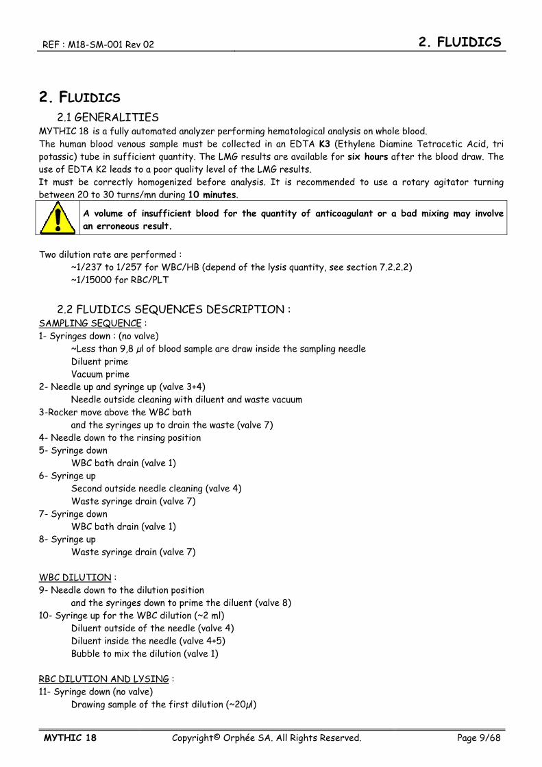
2. FLUIDICS 2.1 GENERALITIES
MYTHIC 18 is a fully automated analyzer performing hematological analysis on whole blood. The human blood venous sample must be collected in an EDTA K3 (Ethylene Diamine Tetracetic Acid, tri potassic) tube in sufficient quantity. The LMG results are available for six hours after the blood draw. The use of EDTA K2 leads to a poor quality level of the LMG results. It must be correctly homogenized before analysis. It is recommended to use a rotary agitator turning between 20 to 30 turns/mn during 10 minutes.
A volume of insufficient blood for the quantity of anticoagulant or a bad mixing may involve an erroneous result.
Two dilution rate are performed : ~1/237 to 1/257 for WBC/HB (depend of the lysis quantity, see section 7.2.2.2) ~1/15000 for RBC/PLT
2.2 FLUIDICS SEQUENCES DESCRIPTION : SAMPLING SEQUENCE : 1- Syringes down : (no valve) ~Less than 9,8 µl of blood sample are draw inside the sampling needle Diluent prime Vacuum prime 2- Needle up and syringe up (valve 3+4) Needle outside cleaning with diluent and waste vacuum 3-Rocker move above the WBC bath and the syringes up to drain the waste (valve 7) 4- Needle down to the rinsing position 5- Syringe down WBC bath drain (valve 1) 6- Syringe up Second outside needle cleaning (valve 4) Waste syringe drain (valve 7) 7- Syringe down WBC bath drain (valve 1) 8- Syringe up Waste syringe drain (valve 7) WBC DILUTION : 9- Needle down to the dilution position and the syringes down to prime the diluent (valve 8) 10- Syringe up for the WBC dilution (~2 ml) Diluent outside of the needle (valve 4) Diluent inside the needle (valve 4+5) Bubble to mix the dilution (valve 1) RBC DILUTION AND LYSING : 11- Syringe down (no valve) Drawing sample of the first dilution (~20µl)
2. FLUIDICS REF : M18-SM-001 Rev 02
Page 10/68 Copyright© Orphée SA. All Rights Reserved. MYTHIC 18
Diluent prime Vacuum prime 12- Needle up and syringe up Rocker move above the RBC bath Needle outside cleaning with diluent and waste vacuum (valve 3+4) 13- Needle down to the rinsing position 14 Syringe up Second outside needle cleaning (valve 4+8) Lysis in the WBC bath (0,3 to 0,5ml) (valve 9) Bubble to mix the dilution (valve 1) 15 Syringe down RBC bath drain (valve 2) 16- Needle down to the dilution position 17- Syringe up for the RBC dilution (~1,5ml) Waste syringe drain (valve 7) Diluent outside of the needle (valve 4+8) Diluent inside the needle (valve 5) Bubble to mix the dilution and diluent to rinse the counting head (valve 6+10+2) MEASUREMENTS : 18- Syringe down to process the vacuum counting (valve 10) 19- First measurement sequences (valve 10) 20- Syringe up Diluent back pressure (valve 4+6) 21- Syringe down to perform the vacuum counting (valve 10) 22- Second measurement sequences (valve 10) DRAIN AND RINSE BATH : 22- Syringe down Cleaning the apertures (valve 11) WBC bath drain (valve 1) RBC bath drain (valve 2) 23- Syringe up RBC bath rinse diluent (valve 4) Waste syringe drain (valve 7) 24- Needle up and syringes up for back flush (valve 4+6) 25- Rocker move above the WBC bath 26- Syringe up WBC bath rinse diluent (valve 4) Waste syringe drain (valve 7) NEEDLE BACK AND WASTE DRAIN : 27- Syringe down Dry the outside of the needle (valve 3) 28- Rocker move in the sampling position 26- Syringe up Waste syringe drain (valve 7) 30- Needle down in sampling position The MYTHIC 18 is ready to perform a new analyze.

REF : M18-SM-001 Rev 02 2. FLUIDICS
MYTHIC 18 Copyright© Orphée SA. All Rights Reserved. Page 11/68
2.3 FLUIDICS VIEW All the fluidics part is on the right side of the instrument and consists of only three modules :
- Sampling module : o Rocker (patent pending) : Manages the rise and descent of the needle.
- Syringe module (patent pending) consists of one block : o Reagent syringes (Diluent, lysis), sampling and air syringes. o Liquid valve manifold assembly and tubing.
- Counting chambers : o WBC and RBC counting chambers and hemoglobin measurement. o Liquid valve manifold assembly and tubing.
Sampling module
Syringe Module
Counting module

2. FLUIDICS REF : M18-SM-001 Rev 02
Page 12/68 Copyright© Orphée SA. All Rights Reserved. MYTHIC 18
2.4 FLUIDICS PARTS DESCRIPTION The hydraulic part of the MYTHIC 18 is very simple and made of only three modules : - Sampling module.
- Counting bath module. - Syringes module.
The modules are connected together by semi rigid tubing.
2.4.1 Sampling module This module (patent pending) enables to draw the sample and to perform the WBC and RBC/PLT dilutions. It is assembled with a rotating rocker moving around a support which maintains the system to move up and down the sampling needle. A very reliable system of rack-gear moves the rocker. The cleaning system of the sampling needle can be removed without tool (see section 9.3.2 in the user manual). The o-ring of the needle included in the cleaning system can also be removed without tool (see section 9.3.2 in the user manual). The maintenance of these parts is very easy to perform.
2.4.2 Counting bath module This module allows to count the WBC and RBC/PLA and to measure the HGB. It is made with a manifold maintaining the reagent commutation valves and the counting bath block with their measurement block including the apertures. The counting bath block assembly and these apertures can be removed without tool (see section 9.3.3/4/5 in the user manual).
2.4.3 Syringes module This module (patent pending) enables : to draw the sample to distribute the reagents to drain the baths to do the vacuum necessary for counting and to push the waste to the waste container. It is made with a manifold maintaining the fluid commutation valves and with the syringes bloc including five syringes : The sampling syringe The lysis syringe The two waste and vacuum/pressure syringes And the diluent syringe. Only one motor drives the five syringes. The diluent input and the waste output are also included in this manifold.

REF : M18-SM-001 Rev 02 2. FLUIDICS
MYTHIC 18 Copyright© Orphée SA. All Rights Reserved. Page 13/68
2.5 FLUIDICS DIAGRAM 2.5.1 General Diagram
2. FLUIDICS REF : M18-SM-001 Rev 02
Page 14/68 Copyright© Orphée SA. All Rights Reserved. MYTHIC 18
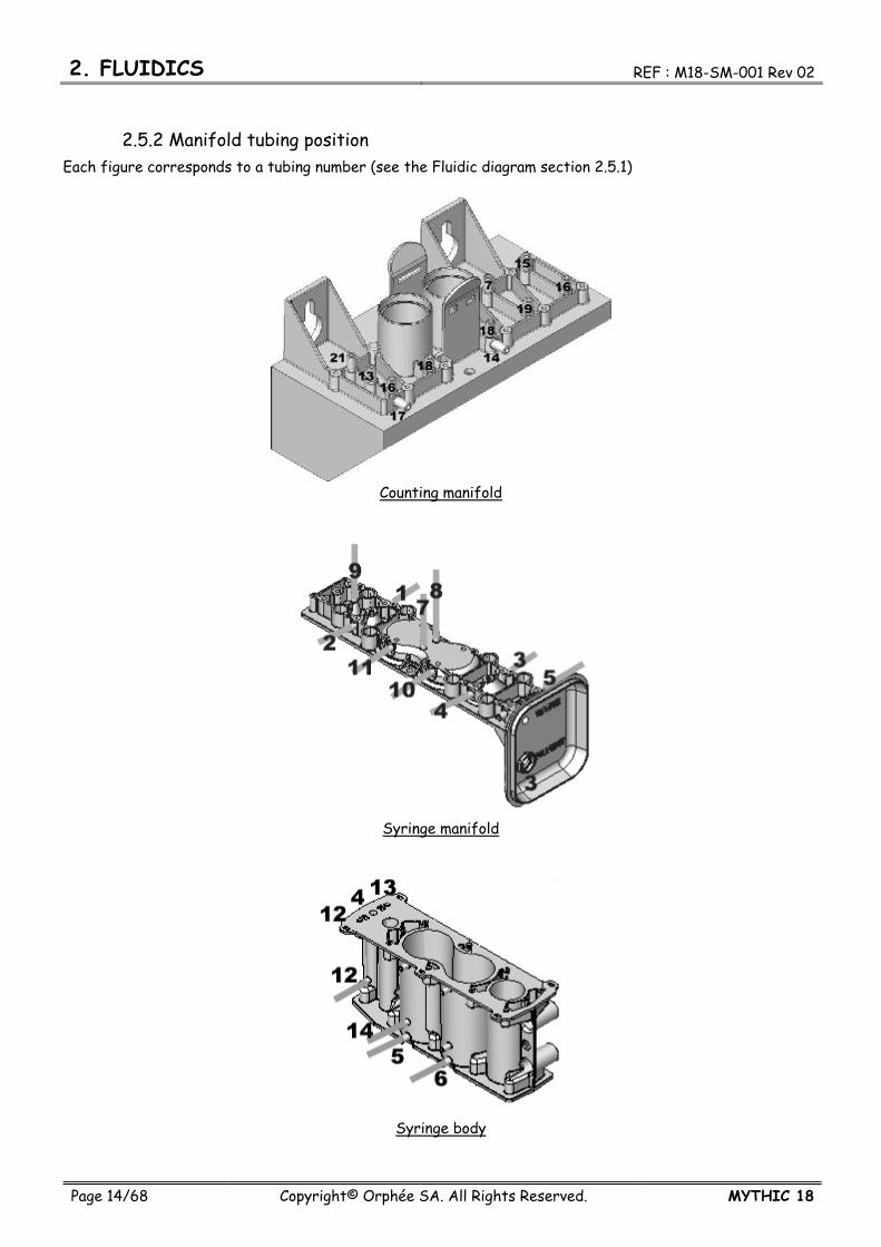
2.5.2 Manifold tubing position Each figure corresponds to a tubing number (see the Fluidic diagram section 2.5.1)
Counting manifold
Syringe manifold
Syringe body
REF : M18-SM-001 Rev 02 2. FLUIDICS
MYTHIC 18 Copyright© Orphée SA. All Rights Reserved. Page 15/68
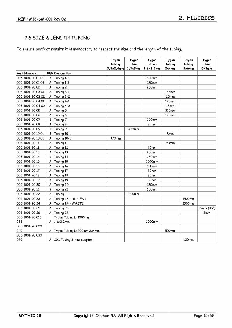
2.6 SIZE & LENGTH TUBING To ensure perfect results it is mandatory to respect the size and the length of the tubing.
Tygon tubing
0,8x2,4mm
Tygon tubing
1,3x3mm
Tygon tubing
1,6x3,2mm
Tygon tubing 2x4mm
Tygon tubing 3x6mm
Tygon tubing 5x8mm
Part Number REV Designation 005-1001-90 01 01 A Tubing 1-1 820mm 005-1001-90 01 02 A Tubing 1-2 180mm 005-1001-90 02 A Tubing 2 250mm 005-1001-90 03 01 A Tubing 3-1 135mm 005-1001-90 03 02 A Tubing 3-2 20mm 005-1001-90 04 01 A Tubing 4-1 175mm 005-1001-90 04 02 A Tubing 4-2 15mm 005-1001-90 05 A Tubing 5 210mm 005-1001-90 06 A Tubing 6 170mm 005-1001-90 07 B Tubing 7 220mm 005-1001-90 08 A Tubing 8 80mm 005-1001-90 09 B Tubing 9 425mm 005-1001-90 10 01 B Tubing 10-1 8mm 005-1001-90 10 02 A Tubing 10-2 370mm 005-1001-90 11 A Tubing 11 90mm 005-1001-90 12 A Tubing 12 60mm 005-1001-90 13 A Tubing 13 250mm 005-1001-90 14 B Tubing 14 250mm 005-1001-90 15 A Tubing 15 1000mm 005-1001-90 16 A Tubing 16 130mm 005-1001-90 17 A Tubing 17 80mm 005-1001-90 18 A Tubing 18 80mm 005-1001-90 19 A Tubing 19 80mm 005-1001-90 20 A Tubing 20 130mm 005-1001-90 21 B Tubing 21 600mm 005-1001-90 22 A Tubing 22 200mm 005-1001-90 23 A Tubing 23 - DILUENT 1500mm 005-1001-90 24 A Tubing 24 - WASTE 1500mm 005-1001-90 25 A Tubing 25 55mm (45°) 005-1001-90 26 A Tubing 26 5mm 005-1001-90 016 032 A
Tygon Tubing L=1000mm 1,6x3.2mm 1000mm
005-1001-90 020 040 A Tygon Tubing L=500mm 2x4mm 500mm 005-1001-90 030 060 A 20L Tubing Straw adaptor 100mm

4. SPECIFICATIONS REF : M18-SM-001 Rev 02
Page 16/68 Copyright© Orphée SA. All Rights Reserved. MYTHIC 18
3. ELECTRIC & ELECTRONIC 3.1 GENERALITIES
Only three boards compose the MYTHIC 18 : - the main board - the preamplifier board - and the GUI board
- In the case of replacement of the main board or preamplifier board, be aware of the sensibility of this board to the electrical static discharge (ESD). - Before operating check the earth connection and use the antistatic bag supply with the board. Please contact your Orphée for more information. - Be careful with the edge of the metal sheets after having dismantled the covers.
3.2 ELECTRICS PARTS VIEW 3.2.1 Main board
The mono electronic board is located between the hydraulic part and the reagent tray. The board, driven by a 32-bit processor, manages the following parts :
- Sample needle, rocker, syringe block motors. - Display and keyboard. - Connexion mode (RS232, Ethernet, …). - Printer. - Measurement (Counting, hemoglobin measurement). - Data processing. - External barcode reader.
REF : M18-SM-001 Rev 02 3. ELECTRICS & ELECTRONICS
MYTHIC 18 Copyright© Orphée SA. All Rights Reserved. Page 17/68
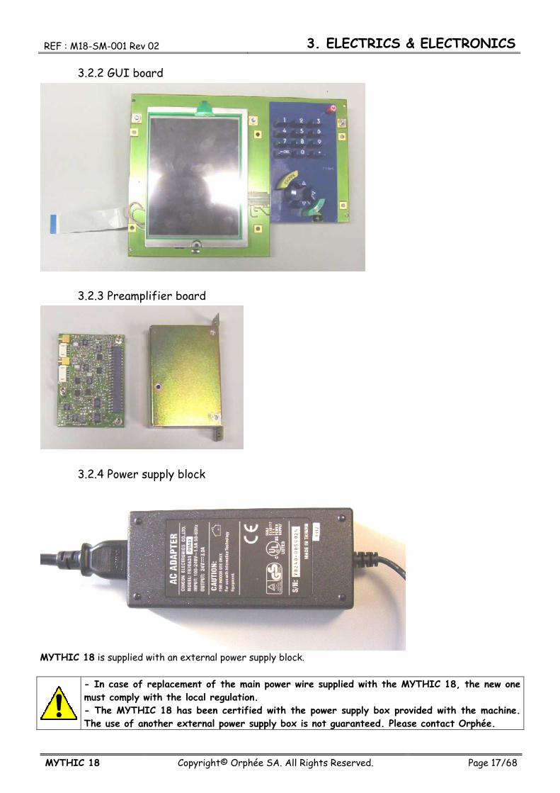
3.2.2 GUI board
3.2.3 Preamplifier board
3.2.4 Power supply block
MYTHIC 18 is supplied with an external power supply block.
- In case of replacement of the main power wire supplied with the MYTHIC 18, the new one must comply with the local regulation. - The MYTHIC 18 has been certified with the power supply box provided with the machine. The use of another external power supply box is not guaranteed. Please contact Orphée.

3. ELECTRICS & ELECTRONICS REF : M18-SM-001 Rev 02
Page 18/68 Copyright© Orphée SA. All Rights Reserved. MYTHIC 18
3.3 ELECTRONIC DIAGRAM

REF : M18-SM-001 Rev 02 3. ELECTRICS & ELECTRONICS
MYTHIC 18 Copyright© Orphée SA. All Rights Reserved. Page 19/68
3.4 WIRING DIAGRAM
3.4.1 General view

3. ELECTRICS & ELECTRONICS REF : M18-SM-001 Rev 02
Page 20/68 Copyright© Orphée SA. All Rights Reserved. MYTHIC 18
3.4.2 Stepper motor

REF : M18-SM-001 Rev 02 3. ELECTRICS & ELECTRONICS
MYTHIC 18 Copyright© Orphée SA. All Rights Reserved. Page 21/68
3.4.3 Rocker optical sensor
3. ELECTRICS & ELECTRONICS REF : M18-SM-001 Rev 02
Page 22/68 Copyright© Orphée SA. All Rights Reserved. MYTHIC 18
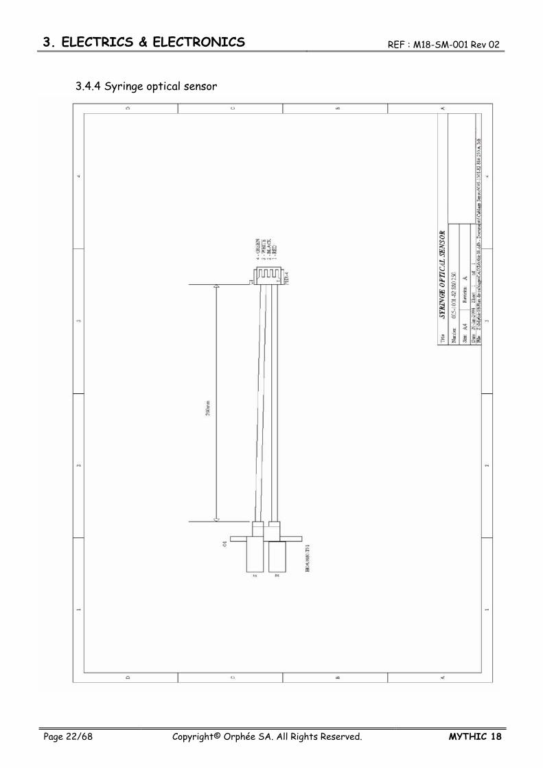
3.4.4 Syringe optical sensor
REF : M18-SM-001 Rev 02 3. ELECTRICS & ELECTRONICS
MYTHIC 18 Copyright© Orphée SA. All Rights Reserved. Page 23/68
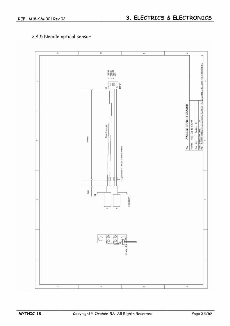
3.4.5 Needle optical sensor

3. ELECTRICS & ELECTRONICS REF : M18-SM-001 Rev 02
Page 24/68 Copyright© Orphée SA. All Rights Reserved. MYTHIC 18
3.4.6 Syringe valve cable
REF : M18-SM-001 Rev 02 3. ELECTRICS & ELECTRONICS
MYTHIC 18 Copyright© Orphée SA. All Rights Reserved. Page 25/68
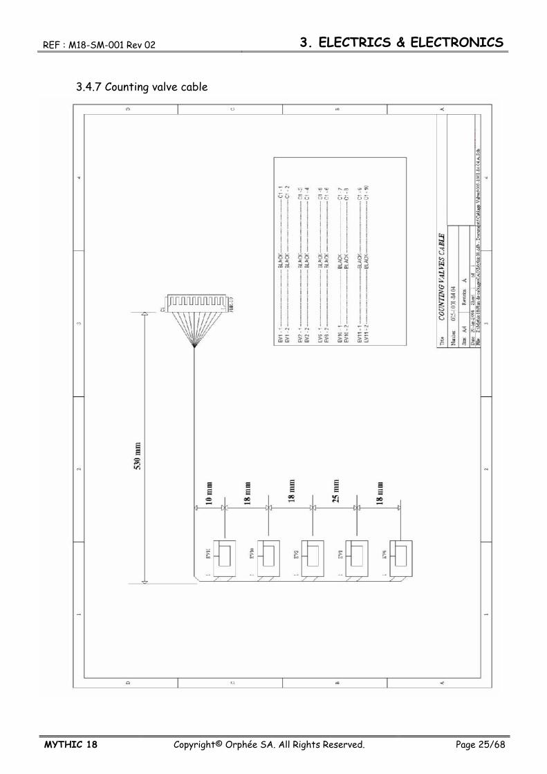
3.4.7 Counting valve cable
3. ELECTRICS & ELECTRONICS REF : M18-SM-001 Rev 02
Page 26/68 Copyright© Orphée SA. All Rights Reserved. MYTHIC 18
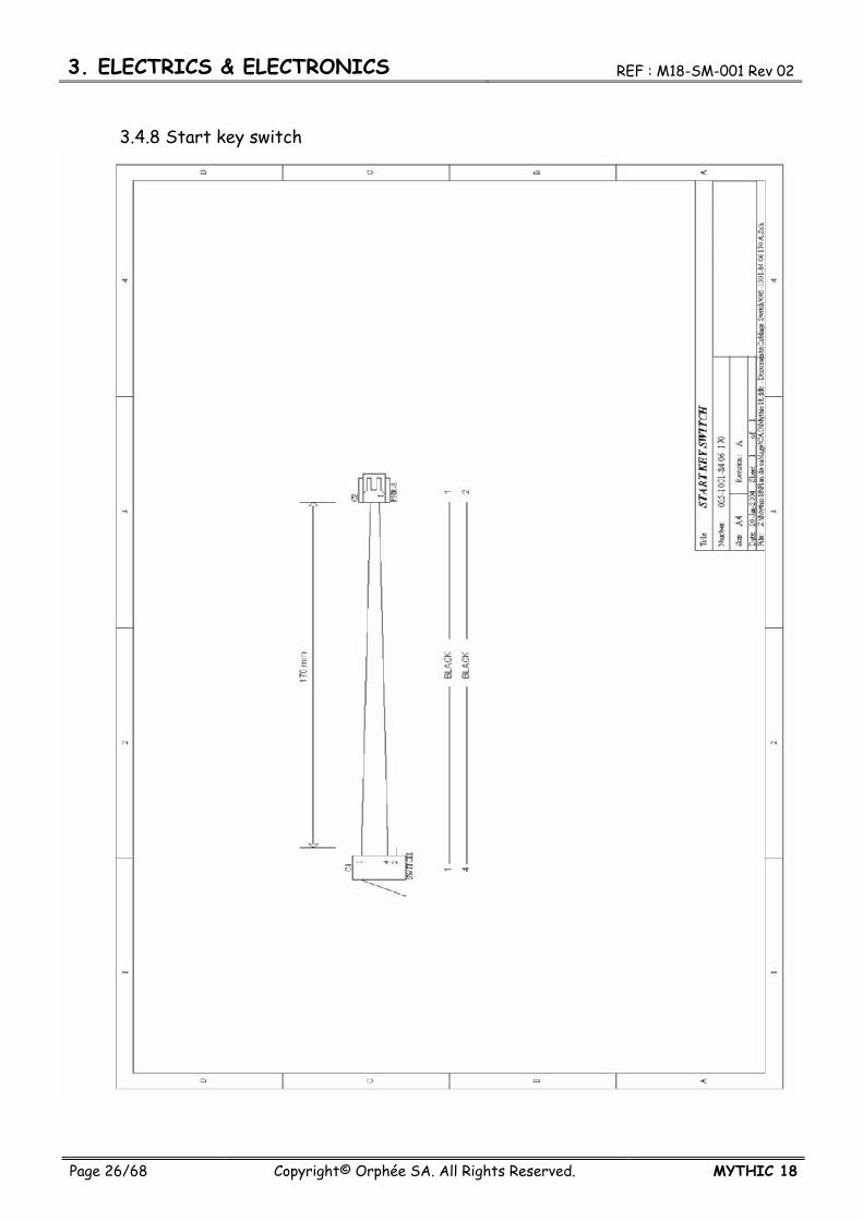
3.4.8 Start key switch

REF : M18-SM-001 Rev 02 3. ELECTRICS & ELECTRONICS
MYTHIC 18 Copyright© Orphée SA. All Rights Reserved. Page 27/68
3.4.9 Fluidic door switch

3. ELECTRICS & ELECTRONICS REF : M18-SM-001 Rev 02
Page 28/68 Copyright© Orphée SA. All Rights Reserved. MYTHIC 18
3.4.10 Temperature sensor

4. SPECIFICATIONS REF : M18-SM-001 Rev 02
Page 29/68 Copyright© Orphée SA. All Rights Reserved. MYTHIC 18
4. SPECIFICATIONS 4.1 ANALYTICAL SPECIFICATIONS
Refer to the User Manual.
4.2 REAGENTS SPECIFICATIONS Refer to the User Manual.
4.3 LIMITATIONS Refer to the User Manual.
REF : M18-SM-001 Rev 02 5. OUTPUT FORMAT
MYTHIC 18 Copyright© Orphée SA. All Rights Reserved. Page 30/68
5. OUTPUT FORMAT The choice of the setting (format, speed …) is explained in page N° 24 of the User’s Manual.
5.2 C2 FORMAT 5.2.1 General principle
Mythic begins frame with headline MYTHIC X ;Y ;Z( ;eventual parameters)[CR] Where : X is the number of the Mythic (maximum 2 characters). Y is the user identification (login) (maximum 10 characters). Z frame identification. The decimal separator is the dot (.). The field separator is « ; ». The line separator and the indicator of end is CR. The uncut frame are : Request of results send with send results. Send calibration pack with results of calibration. All the lines of a frame must be sent. ( If no information, the parameter is not fulfilled). All the identifiant (frame or parameters) are in block letters. All editable text field (Identification, lot) are coded in UTF8 ( non Latin languages management).
5.2.2 FRAMES 5.2.2.1 REQUEST TO SEND RESULTS
Mythic sends results after acknowledgement by the host. Frames used in « Hand-Shake » mode.
5.2.2.1.1 Request to send results MYTHIC X ;Y ;RESULT_READY ;Size[CR]
5.2.2.1.2 ACKNOWLEDGEMENT REQUEST TO SEND RESULTS ACK_RESULT_READY[CR]
5.2.2.1.3 ACKNOWLEDGEMENT RESULTS ACK_RESULT;A;B[CR] Where A : OK or Error Code, B : Reserved.

REF : M18-SM-001 Rev 02 5. OUTPUT FORMAT
MYTHIC 18 Copyright© Orphée SA. All Rights Reserved. Page 31/68
5.2.2.2 ROUTINE RESULTS MYTHIC X ;Y ;RESULT [CR] DATE;jj/mm/aaaa [CR] TIME;hh:mm:ss [CR] MODE;NORMAL [CR] UNIT ; Unité [CR] (0, 1 ou 2) SEQ;Sequence number; 0 [CR] SID;Sample Identification [CR] PID;Patient Identification [CR] ID;Identification [CR] TYPE; Blood Type [CR] TEST; Run Test [CR] OPERATOR ; login Mythic when analysis is performed [CR] WBC; Value;A;B; low panic; low normal; high normal; High panic [CR] RBC; Value;A;B; low panic; low normal; high normal; High panic [CR] HGB; Value;A;B; low panic; low normal; high normal; High panic [CR] HCT; Value;A;B; low panic; low normal; high normal; High panic [CR] MCV; Value;A;B; low panic; low normal; high normal; High panic [CR] MCH; Value;A;B; low panic; low normal; high normal; High panic [CR] MCHC; Value;A;B; low panic; low normal; high normal; High panic [CR] RDW; Value;A;B; low panic; low normal; high normal; High panic [CR] PLT; Value;A;B; low panic; low normal; high normal; High panic [CR] MPV; Value;A;B; low panic; low normal; high normal; High panic [CR] THT; Value;A;B; low panic; low normal; high normal; High panic [CR] PDW; Value;A;B; low panic; low normal; high normal; High panic [CR] LYM%; Value;A;B; low panic; low normal; high normal; High panic [CR] MON%; Value;A;B; low panic; low normal; high normal; High panic [CR] GRA%; Value;A;B; low panic; low normal; high normal; High panic [CR] LYM; Value;A;B; low panic; low normal; high normal; High panic [CR] MON; Value;A;B; low panic; low normal; high normal; High panic [CR] GRA; Value;A;B; low panic; low normal; high normal; High panic [CR] WBC CURVE; Channel value1;… ; Channel value 128 [CR] WBC THRESHOLDS;S1;S2;S3 [CR] RBC CURVE; Channel value1;… ; Channel value 128 [CR] RBC THRESHOLDS; S1;S2 [CR] PLT CURVE; Channel value1;… ; Channel value 128 [CR] PLT THRESHOLDS; S1 [CR] ALARMS;x;x;x;x;x;x;x;x;x;x;x [CR] INTERPRETIVE_WBC;y;y;y;y;y;y;y;y;y;y;y;y [CR] INTERPRETIVE_RBC;y;y;y;y;y;y;y;y;y;y;y;y [CR] INTERPRETIVE_PLT;y;y;y;y;y;y;y;y;y;y;y;y [CR] COMMENT; RUO message if necessary END_RESULT; Checksum value [CR]

5. OUTPUT FORMAT REF : M18-SM-001 Rev 02
Page 32/68 Copyright© Orphée SA. All Rights Reserved. MYTHIC 18
A : None or * (Rejection flag) B : None or D or H or h or l or L (Out of limit flags) x : None or Alarm. y : None or pathologic message. S1 S2 S3 : thresholds of the curves (Between 0 and 127). This frame is available for LMG test. Numeric values should be replaced by +++++ (5 plus) for a out of range result or by ….. (5 dots) donor invalid results. If RUO mode is not activated, PCT and PDW are not transmitted.
5.2.2.2.1 Alarm list. S-UP NOT DONE S-UP FAIL QC NOT DONE QC FAIL INS-M INS-T INS-P INS-R INS-H L1 L2 L3 L4 L5 R1 R2 P1 P2 P3
5.2.2.2.2 WBC pathologic alarms LEU> LEU< LYM> LYM< GRA> GRA< MON> NO_INTERPRETATION
REF : M18-SM-001 Rev 02 5. OUTPUT FORMAT
MYTHIC 18 Copyright© Orphée SA. All Rights Reserved. Page 33/68
5.2.2.2.3 RBC pathologic messages
ANE ERY> MICRO MACRO MICR> MICR>> MICR>>> MACR> MACR>> MACR>>> ANIS> ANIS>> ANIS>>> HYPOCR COLDAGG NO_INTERPRETATION
5.2.2.2.4 PLT pathologic messages THR> THR< MACROP PLTAGGR MICROC SCHIZ CELLD NO_INTERPRETATION
5.2.2.3 CALIBRATION
MYTHIC X;Y;CALIBRATION;Y ;Calibration date ;calibration time ;LOT ;Expiry date ;Creation date ;Creation time ; ;X ;A ;B ;C ;D ;F ;Number of results [CR] WBC; target value ; tolerance [CR] RBC; target value ; tolerance [CR] HGB; target value ; tolerance [CR] HCT; target value ; tolerance [CR] PLT; target value ; tolerance [CR] END_CALI ; Checksum [CR] Where X : User who creates the lot. Y : User who performs the calibration. A, B, C, D and F are the coefficient of the calibration, for respectively, WBC, RBC, HGB, HCT and PLT. Follow N results which served for calibration. In case of manual input of the coefficients, information of the lot are empty and the number of results is null. Acknowledgement of the calibration is done by the frame ACK_CALI ;Lot;A [CR] Where A : OK or Error Code.

5. OUTPUT FORMAT REF : M18-SM-001 Rev 02
Page 34/68 Copyright© Orphée SA. All Rights Reserved. MYTHIC 18
5.2.2.3.1 Results
MYTHIC X ;Y ;RESULT [CR] DATE;dd/mm/yyyy [CR] TIME;hh:mm:ss [CR] MODE;CALIBRATION [CR] UNIT ; Unit [CR] SEQ;Number of sequence; 0 [CR] TEST;LMG [CR] OPERATOR ; login Mythic when analysis is performed [CR] WBC; Numerical Value; A;B;;;; [CR] RBC; Numerical Value; A;B;;;; [CR] HGB; Numerical Value; A;B;;;; [CR] HCT; Numerical Value; A;B;;;; [CR] PLT; Numerical Value; A;B;;;; [CR] END_RESULT; Checksum value [CR] A and B like routine results.
5.2.2.4 QC 5.2.2.4.1 Results
MYTHIC X ;Y ;RESULT [CR] DATE;dd/mm/yyyy [CR] TIME;hh:mm:ss [CR] MODE;QC [CR] UNIT ; Unit [CR] SEQ;Number of sequence; 0 [CR] LOT, Number of lot [CR] (Maximum 10 characters) LOT DATE; Creation Dateof the lot ; time of creation [CR] EXPIRY DATE; Expiry date [CR] USER; User (login) who created the lot [CR] TEST;LMG [CR] OPERATOR ; login Mythic when analysis is performed [CR] WBC; Value;A;B; Target - tolerance;;; Target + tolerance [CR] RBC; Value;A;B; Target - tolerance;;; Target + tolerance [CR] HGB; Value;A;B; Target - tolerance;;; Target + tolerance [CR] HCT; Value;A;B; Target - tolerance;;; Target + tolerance [CR] MCV; Value;A;B; Target - tolerance;;; Target + tolerance [CR] MCH; Value;A;B; Target - tolerance;;; Target + tolerance [CR] MCHC; Value;A;B; Target - tolerance;;; Target + tolerance [CR] RDW; Value;A;B; Target - tolerance;;; Target + tolerance [CR] PLT; Value;A;B; Target - tolerance;;; Target + tolerance [CR] MPV; Value;A;B; Target - tolerance;;; Target + tolerance [CR] THT; Value;A;B; Target - tolerance;;; Target + tolerance [CR] PDW; Value;A;B; Target - tolerance;;; Target + tolerance [CR] LYM%; Value;A;B; Target - tolerance;;; Target + tolerance [CR] MON%; Value;A;B; Target - tolerance;;; Target + tolerance [CR] GRA%; Value;A;B; Target - tolerance;;; Target + tolerance [CR] LYM; Value;A;B; Target - tolerance;;; Target + tolerance [CR] MON; Value;A;B; Target - tolerance;;; Target + tolerance [CR]
REF : M18-SM-001 Rev 02 5. OUTPUT FORMAT
MYTHIC 18 Copyright© Orphée SA. All Rights Reserved. Page 35/68
GRA; Value;A;B; Target - tolerance;;; Target + tolerance [CR] END_RESULT; Cheksum value [CR] A and B like routine results.
5.2.2.5 REPEATABILITY 5.2.2.5.1 Results
MYTHIC X ;Y ;RESULT [CR] DATE;dd/mm/yyyy [CR] TIME;hh:mm:ss [CR] MODE;REPEATABILITY [CR] UNIT ; Unit [CR] SEQ;Number of sequence; 0 [CR] TEST;LMG [CR] OPERATOR ; login Mythic when analysis is performed [CR] WBC; Value;A;B;;;; [CR] RBC; Value; A;B;;;; [CR] HGB; Value; A;B;;;; [CR] HCT; Value; A;B;;;; [CR] MCV; Value; A;B;;;; [CR] MCH; Value; A;B;;;; [CR] MCHC; Value; A;B;;;; [CR] RDW; Value; A;B;;;; [CR] PLT; Value; A;B;;;; [CR] MPV; Value; A;B;;;; [CR] THT; Value; A;B;;;; [CR] PDW; Value; A;B;;;; [CR] LYM%; Value; A;B;;;; [CR] MON%; Value; A;B;;;; [CR] GRA%; Value; A;B;;;; [CR] LYM; Value; A;B;;;; [CR] MON; Value; A;B;;;; [CR] GRA; Value; A;B;;;; [CR] END_RESULT; Checksum value [CR] A and B like routine results.
5.2.3 CHECKSUM For the frames with a few number of lines, the block is finished with an end line with a checksum. This sum is calculated from the beginning of the headline to the end of the line finishing the block. The algorithm of the calculation for the sum is : CRC = 0xFFFF For each byte Work on high neeble: Indix = byte XOR CRC Indix = Indix AND 000F CRC = Table(Indix) XOR (CRC divided by 16) Work on low neeble:

5. OUTPUT FORMAT REF : M18-SM-001 Rev 02
Page 36/68 Copyright© Orphée SA. All Rights Reserved. MYTHIC 18
Indix = byte divided by 16 Indix = Indix XOR CRC Indix = Indix AND 000F CRC = Table(Indix) XOR (CRC divided by 16) Example in C language: /*Hash table :*/ static const unsigned short ausCrcTab1[] = { 0x0000, 0xCC01,0xD801,0x1400,0xF001,0x3C00,0x2800,0xE401, 0xA001,0x6C00,0x7800,0xB401,0x5000,0x9C01,0x8801,0x4400, }; /* CRC computing */ unsigned short calc_crc(unsigned char *pucData, long lSize) { unsigned short usAcc1 = 0xFFFF; while ( lSize > 0 ) { /* gestion par quartet du calcul */ usAcc1 = ausCrcTab1[(*pucData ^ usAcc1) & 15] ^ (usAcc1 >> 4); usAcc1 = ausCrcTab1[((*pucData >> 4) ^ usAcc1) & 15] ^ (usAcc1 >> 4); pucData++; lSize--; } return(usAcc1); } ^ : XOR. >> : Logical shift right. & : logical AND.
6. PARTS LISTE & BLOW UP VIEW REF : M18-SM-001 Rev 02
Page 37/68 Copyright© Orphée SA. All Rights Reserved. MYTHIC 18
6. PARTS LIST & BLOW UP VIEW
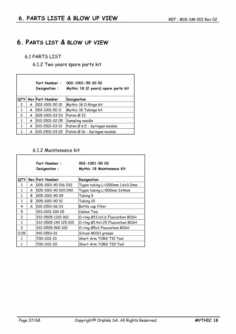
6.1 PARTS LIST 6.1.2 Two years spare parts kit
Part Number : 002-1001-50 20 02 Designation : Mythic 18 (2 years) spare parts kit QTY Rev Part Number Designation
2 A 002-1001-50 10 Mythic 18 O-Rings kit 1 A 002-1001-50 11 Mythic 18 Tubings kit 2 A 005-1001-03 03 Piston Ø 22 1 A 010-2501-02 05 Sampling needle 1 A 010-2501-03 01 Piston Ø 6.5 - Syringes module 1 A 010-2501-03 02 Piston Ø 16 - Syringes module
6.1.2 Maintenance kit Part Number : 002-1001-50 02 Designation : Mythic 18 Maintenance Kit QTY Rev Part Number Designation
1 A 005-1001-90 016 032 Tygon tubing L=1000mm 1.6x3.2mm 1 A 005-1001-90 020 040 Tygon tubing L=500mm 2x4mm 1 B 005-1001-90 09 Tubing 9 1 B 005-1001-90 10 Tubing 10 4 A 010-2501-06 03 Bottle cap filter 5 153-0101-100 25 Cables Ties 2 312-0505-1310 160 O-ring Ø13.1x1.6 Fluocarbon 80SH 1 312-0505-140 125 010 O-ring Ø1.4x1.25 Fluocarbon 80SH 2 312-0505-500 100 O-ring Ø5x1 Fluocarbon 80SH
0,05 410-0501-01 Silicon M1011 grease 1 700-1101-10 Short Arm TORX T10 Tool 1 700-1101-20 Short Arm TORX T20 Tool
6. PARTS LISTE & BLOW UP VIEW REF : M18-SM-001 Rev 02
Page 38/68 Copyright© Orphée SA. All Rights Reserved. MYTHIC 18
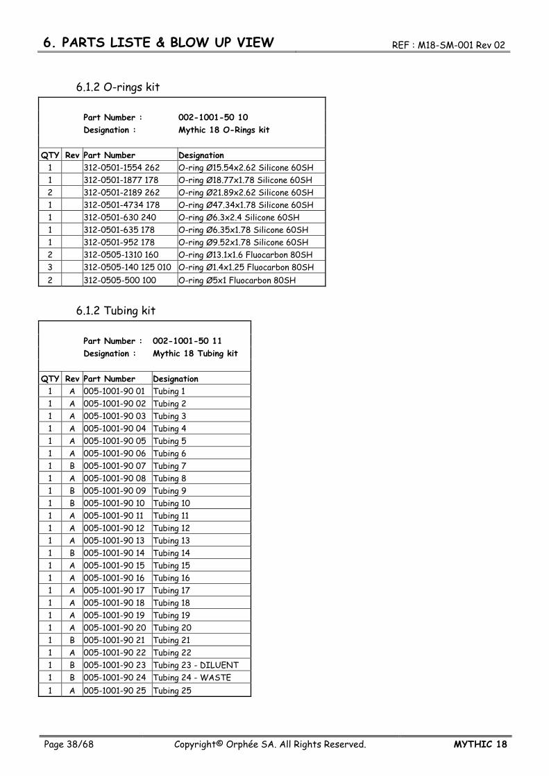
6.1.2 O-rings kit Part Number : 002-1001-50 10 Designation : Mythic 18 O-Rings kit QTY Rev Part Number Designation
1 312-0501-1554 262 O-ring Ø15.54x2.62 Silicone 60SH 1 312-0501-1877 178 O-ring Ø18.77x1.78 Silicone 60SH 2 312-0501-2189 262 O-ring Ø21.89x2.62 Silicone 60SH 1 312-0501-4734 178 O-ring Ø47.34x1.78 Silicone 60SH 1 312-0501-630 240 O-ring Ø6.3x2.4 Silicone 60SH 1 312-0501-635 178 O-ring Ø6.35x1.78 Silicone 60SH 1 312-0501-952 178 O-ring Ø9.52x1.78 Silicone 60SH 2 312-0505-1310 160 O-ring Ø13.1x1.6 Fluocarbon 80SH 3 312-0505-140 125 010 O-ring Ø1.4x1.25 Fluocarbon 80SH 2 312-0505-500 100 O-ring Ø5x1 Fluocarbon 80SH
6.1.2 Tubing kit Part Number : 002-1001-50 11 Designation : Mythic 18 Tubing kit QTY Rev Part Number Designation
1 A 005-1001-90 01 Tubing 1 1 A 005-1001-90 02 Tubing 2 1 A 005-1001-90 03 Tubing 3 1 A 005-1001-90 04 Tubing 4 1 A 005-1001-90 05 Tubing 5 1 A 005-1001-90 06 Tubing 6 1 B 005-1001-90 07 Tubing 7 1 A 005-1001-90 08 Tubing 8 1 B 005-1001-90 09 Tubing 9 1 B 005-1001-90 10 Tubing 10 1 A 005-1001-90 11 Tubing 11 1 A 005-1001-90 12 Tubing 12 1 A 005-1001-90 13 Tubing 13 1 B 005-1001-90 14 Tubing 14 1 A 005-1001-90 15 Tubing 15 1 A 005-1001-90 16 Tubing 16 1 A 005-1001-90 17 Tubing 17 1 A 005-1001-90 18 Tubing 18 1 A 005-1001-90 19 Tubing 19 1 A 005-1001-90 20 Tubing 20 1 B 005-1001-90 21 Tubing 21 1 A 005-1001-90 22 Tubing 22 1 B 005-1001-90 23 Tubing 23 - DILUENT 1 B 005-1001-90 24 Tubing 24 - WASTE 1 A 005-1001-90 25 Tubing 25

REF : M18-SM-001 Rev 02 6. PARTS LISTE & BLOW UP VIEW
MYTHIC 18 Copyright© Orphée SA. All Rights Reserved. Page 39/68
6.1.2 All spare parts Mythic 18 Spare Parts Rev 3 Designation Part Number Qty/Pkg Unit 1L Straw 005-1001-06 01 1 UNIT40P Flexible Flat Cable 170-4001-05 210 1 UNIT5/10-20L Adaptator 300-1009-05 1020 1 UNIT70W switching adapter 050-1001-01 70 24 1 UNITBottle cap filter 010-2501-06 03 10 UNITCounting Chambers 005-1001-01 01 1 UNITCounting Manifold 010-2501-01 03 1 UNITCounting Valves Cable 005-1001-84 04 1 UNITElectrovalve 2/2 309-0501-152401 1 UNITElectrovalve 3/2 309-0501-152402 1 UNITElectrovalve 3/2 - 1.6mm 309-0501-01 016 1 UNITFluidic Door Switch 002-1001-84 06 370 1 UNITFront cover 005-1001-04 02 1 UNITLubriplate DS-ES 410-0502-01 1 UNITLyse Spring 005-1001-86 01 1 UNITMythic 18 (2 years) spare part kit 002-1001-50 20 02 1 UNITMythic 18 CPU Board 205-1001-01 1 UNITMythic 18 CPU Board & Preamplifier 002-2001-04 1 UNITMythic 18 IHM Board 205-1001-02 1 UNITMythic 18 Maintenance Kit 002-1001-50 02 1 UNITMythic 18 O-Rings kit 002-1001-50 10 1 UNITMythic 18 Preampifier Board 205-1001-03 1 UNITMythic 18 Tubings kit 002-1001-50 11 1 UNITNeedle Belt 353-0301-08 120 19 1 UNITNeedle carriage 010-2501-02 02 1 UNITNeedle Motor 005-1001-02 02 1 UNITNeedle Optical Sensor 005-1001-82 880 300 1 UNITO-ring Ø1.07x1.27 Fluocarbon 80SH 312-0505-107 127 10 UNITO-ring Ø1.4x1.25 Fluocarbon 80SH 312-0505-140 125 010 10 UNITO-ring Ø13.1x1.6 Fluocarbon 80SH 312-0505-1310 160 10 UNITO-ring Ø15.54x2.62 Silicone 60SH 312-0501-1554 262 10 UNITO-ring Ø18.77x1.78 Silicone 60SH 312-0501-1877 178 10 UNITO-ring Ø21.89x2.62 Silicone 60SH 312-0501-2189 262 10 UNITO-ring Ø47.34x1.78 Silicone 60SH 312-0501-4734 178 10 UNITO-ring Ø5x1 Fluocarbon 80SH 312-0505-500 100 10 UNITO-ring Ø6.35x1.78 Silicone 60SH 312-0501-635 178 10 UNITO-ring Ø6.3x2.4 Silicone 60SH 312-0501-630 240 10 UNITO-ring Ø9.52x1.78 Silicone 60SH 312-0501-952 178 10 UNITO-Ring spacer 010-2501-03 10 1 UNIT
6. PARTS LISTE & BLOW UP VIEW REF : M18-SM-001 Rev 02
Page 40/68 Copyright© Orphée SA. All Rights Reserved. MYTHIC 18
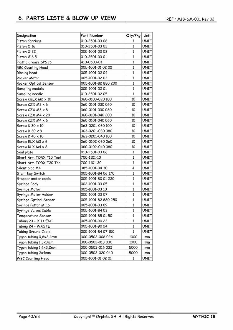
Designation Part Number Qty/Pkg Unit Piston Carriage 010-2501-03 08 1 UNIT Piston Ø 16 010-2501-03 02 1 UNIT Piston Ø 22 005-1001-03 03 1 UNIT Piston Ø 6.5 010-2501-03 01 1 UNIT Plastic grease SPG35 410-0503-01 1 UNIT RBC Counting Head 005-1001-01 02 02 1 UNIT Rinsing head 005-1001-02 04 1 UNIT Rocker Motor 005-1001-02 03 1 UNIT Rocker Optical Sensor 005-1001-82 880 200 1 UNIT Sampling module 005-1001-02 01 1 UNIT Sampling needle 010-2501-02 05 1 UNIT Screw CBLX M2 x 10 360-0103-020 100 10 UNIT Screw CZX M3 x 6 360-0101-030 060 10 UNIT Screw CZX M3 x 8 360-0101-030 080 10 UNIT Screw CZX M4 x 20 360-0101-040 200 10 UNIT Screw CZX M4 x 6 360-0101-040 060 10 UNIT Screw K 30 x 10 363-0201-030 100 10 UNIT Screw K 30 x 8 363-0201-030 080 10 UNIT Screw K 40 x 10 363-0201-040 100 10 UNIT Screw RLX M3 x 6 360-0102-030 060 10 UNIT Screw RLX M4 x 8 360-0102-040 080 10 UNIT Seal plate 010-2501-03 06 1 UNIT Short Arm TORX T10 Tool 700-1101-10 1 UNIT Short Arm TORX T20 Tool 700-1101-20 1 UNIT Silent bloc M4 385-1001-04 30 4 UNIT Start key Switch 005-1001-84 06 170 1 UNIT Stepper motor cable 005-1001-80 01 220 1 UNIT Syringe Body 002-1001-03 05 1 UNIT Syringe Motor 005-1001-03 10 1 UNIT Syringe Motor Holder 005-1001-03 07 1 UNIT Syringe Optical Sensor 005-1001-82 880 250 1 UNIT Syringe Piston Ø 1.6 005-1001-03 09 1 UNIT Syringe Valves Cable 005-1001-84 03 1 UNIT Temperature Sensor 005-1001-85 01 50 1 UNIT Tubing 23 - DILUENT 005-1001-90 23 1 UNIT Tubing 24 - WASTE 005-1001-90 24 1 UNIT Tubing Ground Cable 005-1001-84 07 150 1 UNIT Tygon tubing 0,8x2,4mm 300-0502-008 024 1000 mm Tygon tubing 1,3x3mm 300-0502-013 030 1000 mm Tygon tubing 1,6x3,2mm 300-0502-016 032 5000 mm Tygon tubing 2x4mm 300-0502-020 040 5000 mm WBC Counting Head 005-1001-01 02 01 1 UNIT

REF : M18-SM-001 Rev 02 6. PARTS LISTE & BLOW UP VIEW
MYTHIC 18 Copyright© Orphée SA. All Rights Reserved. Page 41/68
6.2 BLOW UP VIEW 6.2.1 Counting Module
Rep Part Number Designation 1 005-1001-01 01 Counting chambers 2 010-2501-01 03 Counting manifold 3 005-1001-01 02 01 WBC Counting Head 4 005-1001-01 02 02 RBC Counting Head 5 312-0505-500 100 O-ring Ø5x1 Silicone 80SH 6 360-0101-030 060 Screw CZX M3 x 6 7 312-0505-1310 160 O-ring Ø13.1x1.6 Fluocarbon 80SH
6. PARTS LISTE & BLOW UP VIEW REF : M18-SM-001 Rev 02
Page 42/68 Copyright© Orphée SA. All Rights Reserved. MYTHIC 18
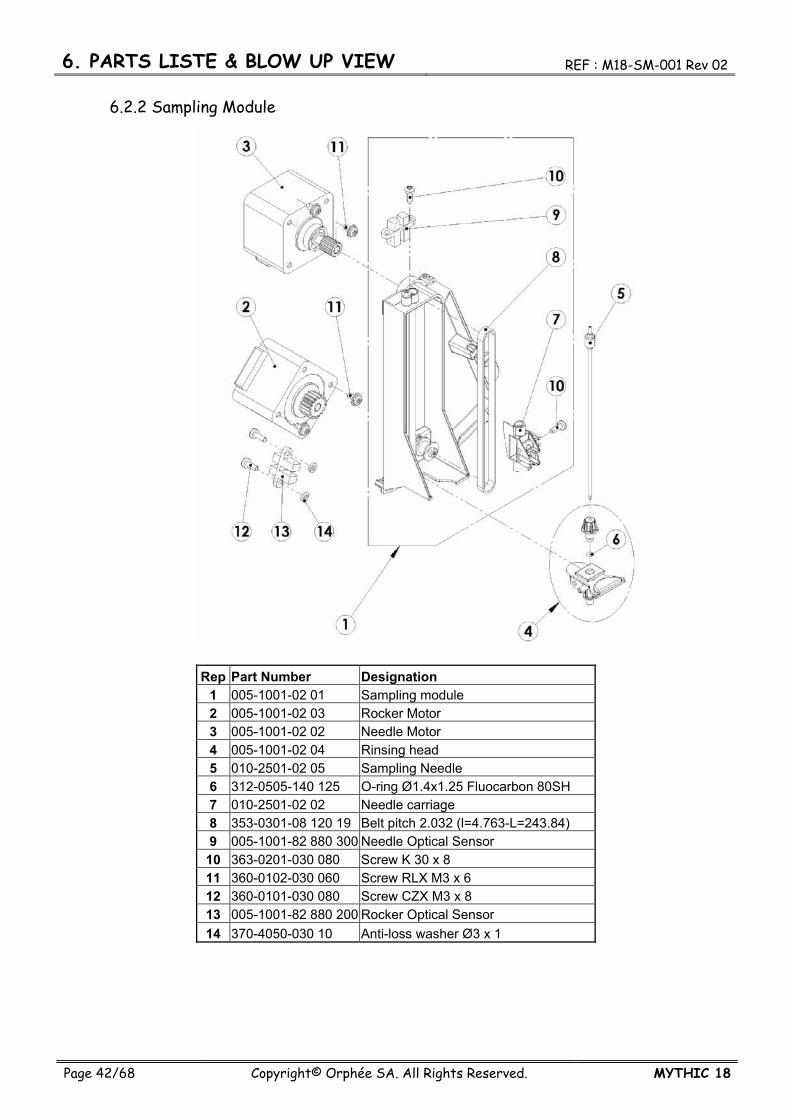
6.2.2 Sampling Module
Rep Part Number Designation 1 005-1001-02 01 Sampling module 2 005-1001-02 03 Rocker Motor 3 005-1001-02 02 Needle Motor 4 005-1001-02 04 Rinsing head 5 010-2501-02 05 Sampling Needle 6 312-0505-140 125 O-ring Ø1.4x1.25 Fluocarbon 80SH 7 010-2501-02 02 Needle carriage 8 353-0301-08 120 19 Belt pitch 2.032 (l=4.763-L=243.84) 9 005-1001-82 880 300 Needle Optical Sensor
10 363-0201-030 080 Screw K 30 x 8 11 360-0102-030 060 Screw RLX M3 x 6 12 360-0101-030 080 Screw CZX M3 x 8 13 005-1001-82 880 200 Rocker Optical Sensor 14 370-4050-030 10 Anti-loss washer Ø3 x 1

REF : M18-SM-001 Rev 02 6. PARTS LISTE & BLOW UP VIEW
MYTHIC 18 Copyright© Orphée SA. All Rights Reserved. Page 43/68
6.2.3 Syringe Module
Rep Part Number Designation 1 002-1001-03 05 Syringes body 2 010-2501-03 06 Seal plate 3 010-2501-03 02 Piston Ø 16 4 005-1001-03 03 Piston Ø 22 5 010-2501-03 01 Piston Ø 6.5 6 005-1001-03 09 Syringe Piston Ø 1.6 7 312-0501-1554 262 O-ring Ø15.54x2.62 Silicone 60SH 8 312-0501-2189 262 O-ring Ø21.89x2.62 Silicone 60SH 9 312-0501-630 240 O-ring Ø6.3x2.4 Silicone 60SH 10 312-0505-140 125 O-ring Ø1.4x1.25 Fluocarbon 80SH 11 010-2501-03 10 O-ring spacer 12 363-0201-030 100 Screw K 30 x 10

6. PARTS LISTE & BLOW UP VIEW REF : M18-SM-001 Rev 02
Page 44/68 Copyright© Orphée SA. All Rights Reserved. MYTHIC 18
Rep Part Number Designation 1 005-1001-03 10 Syringes Motor 2 360-0101-030 080 Screw CZX M3 x 8 3 363-0201-030 100 Screw K 30 x 10 4 360-0101-040 200 Screw CZX M4 x 20 5 385-1001-04 30 Silent bloc M4 6 005-1001-82 880 250 Syringe Optical Sensor 7 363-0201-030 080 Screw K 30 x 8
REF : M18-SM-001 Rev 02 6. PARTS LISTE & BLOW UP VIEW
MYTHIC 18 Copyright© Orphée SA. All Rights Reserved. Page 45/68
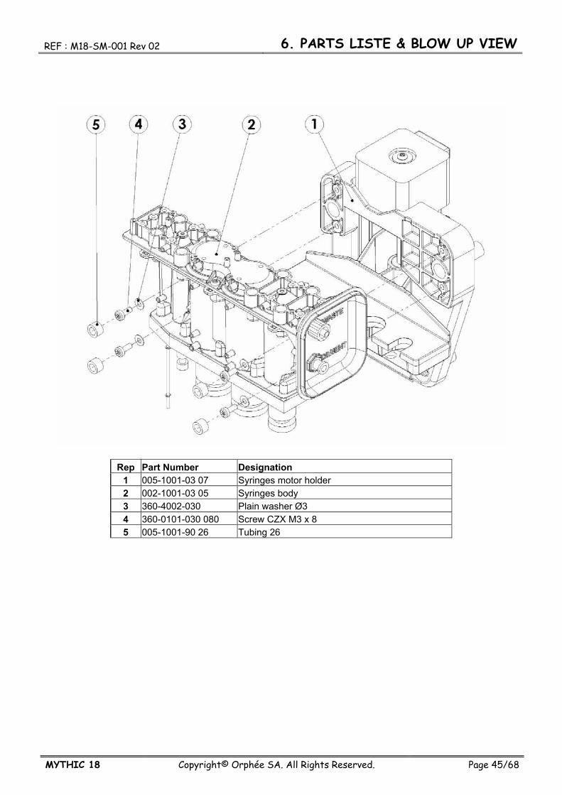
Rep Part Number Designation 1 005-1001-03 07 Syringes motor holder 2 002-1001-03 05 Syringes body 3 360-4002-030 Plain washer Ø3 4 360-0101-030 080 Screw CZX M3 x 8 5 005-1001-90 26 Tubing 26

6. PARTS LISTE & BLOW UP VIEW REF : M18-SM-001 Rev 02
Page 46/68 Copyright© Orphée SA. All Rights Reserved. MYTHIC 18
6.2.4 CPU-PREAMPLIFIER Module
Rep Part Number Designation
1 002-2001-04 Mythic 18 CPU & Preamplifier board 2 205-1001-01 Mythic 18 CPU board 3 205-1001-03 Mythic 18 Preamplifier board 4 360-0101-030 060 Screw CZX M3 x 6 5 360-0101-040 060 Screw CZX M4 x 6 6 360-6203-040 600 Hexagonal spacer FF M4 x 60 8 360-0102-040 080 Screw RLX M4 x 8
REF : M18-SM-001 Rev 02 6. PARTS LISTE & BLOW UP VIEW
MYTHIC 18 Copyright© Orphée SA. All Rights Reserved. Page 47/68
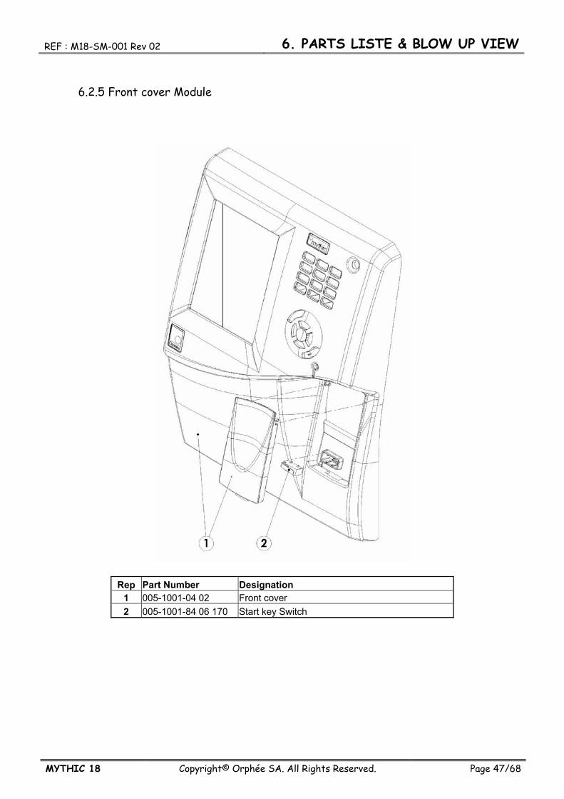
6.2.5 Front cover Module
Rep Part Number Designation 1 005-1001-04 02 Front cover 2 005-1001-84 06 170 Start key Switch

REF : M18-SM-001 Rev 02 7. SOTWARE
MYTHIC 18 Copyright© Orphée SA. All Rights Reserved. Page 48/68
7. SOFTWARE 7.1 INTRODUCTION
Please refer to the User’s Manuel for explanation of the software operation.
7.2 SPECIFIC TECHNICIAN DISPLAY The following section describe the software operation which are only accessible with the technician and super technician passwords.
7.2.1 Technician password The unmodified technician password is : 8SUP.
- It is strictly forbidden to disclose the technician password to the final customer. - In such case, Orphée guarantee will not be valid.
7.2.2 Technician display The technician display are accessible from MAIN SCREEN then SERVICE then TECHNICIAN.
7.2.2.1 Technician
- allows access to the adjustment of the counting parameters and lysis quantity. These adjustments are possible with the super technician code only. - For an access to the latex adjustment and HGB blanc adjustment press
- allows to test the aperture current.
- see section 8.3.
- allows to fill up the log accessible from the MAIN MENU.
REF : M18-SM-001 Rev 02 7. SOTWARE
MYTHIC 18 Copyright© Orphée SA. All Rights Reserved. Page 49/68
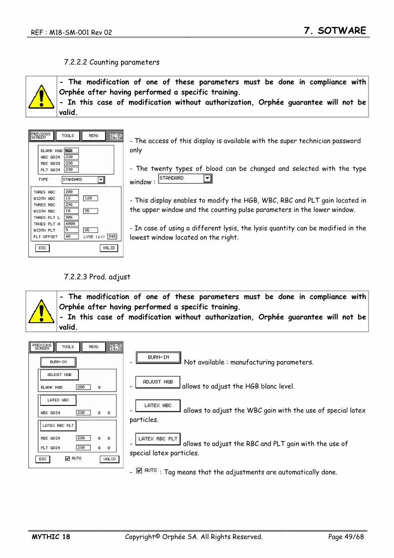
7.2.2.2 Counting parameters
- The modification of one of these parameters must be done in compliance with Orphée after having performed a specific training. - In this case of modification without authorization, Orphée guarantee will not be valid.
- The access of this display is available with the super technician password only - The twenty types of blood can be changed and selected with the type
window : - This display enables to modify the HGB, WBC, RBC and PLT gain located in the upper window and the counting pulse parameters in the lower window. - In case of using a different lysis, the lysis quantity can be modified in the lowest window located on the right.
7.2.2.3 Prod. adjust
- The modification of one of these parameters must be done in compliance with Orphée after having performed a specific training. - In this case of modification without authorization, Orphée guarantee will not be valid.
- Not available : manufacturing parameters.
- allows to adjust the HGB blanc level.
- allows to adjust the WBC gain with the use of special latex particles.
- allows to adjust the RBC and PLT gain with the use of special latex particles. - : Tag means that the adjustments are automatically done.
7. SOTWARE REF : M18-SM-001 Rev 02
Page 50/68 Copyright© Orphée SA. All Rights Reserved. MYTHIC 18
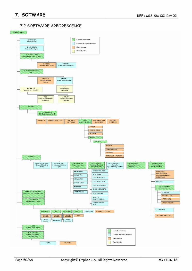
7.2 SOFTWARE ARBORESCENCE
8. MAINTENANCE REF : M18-SM-001 Rev 02
Page 51/68 Copyright© Orphée SA. All Rights Reserved. MYTHIC 18
8. MAINTENANCE The quality of the results and the reliability of the MYTHIC 18 are directly linked to the strict respect of the maintenance hereafter described.
To perform the maintenance and the repair described in this section, it is mandatory to wear rubber gloves and wash hands with a disinfectant after completion of work.
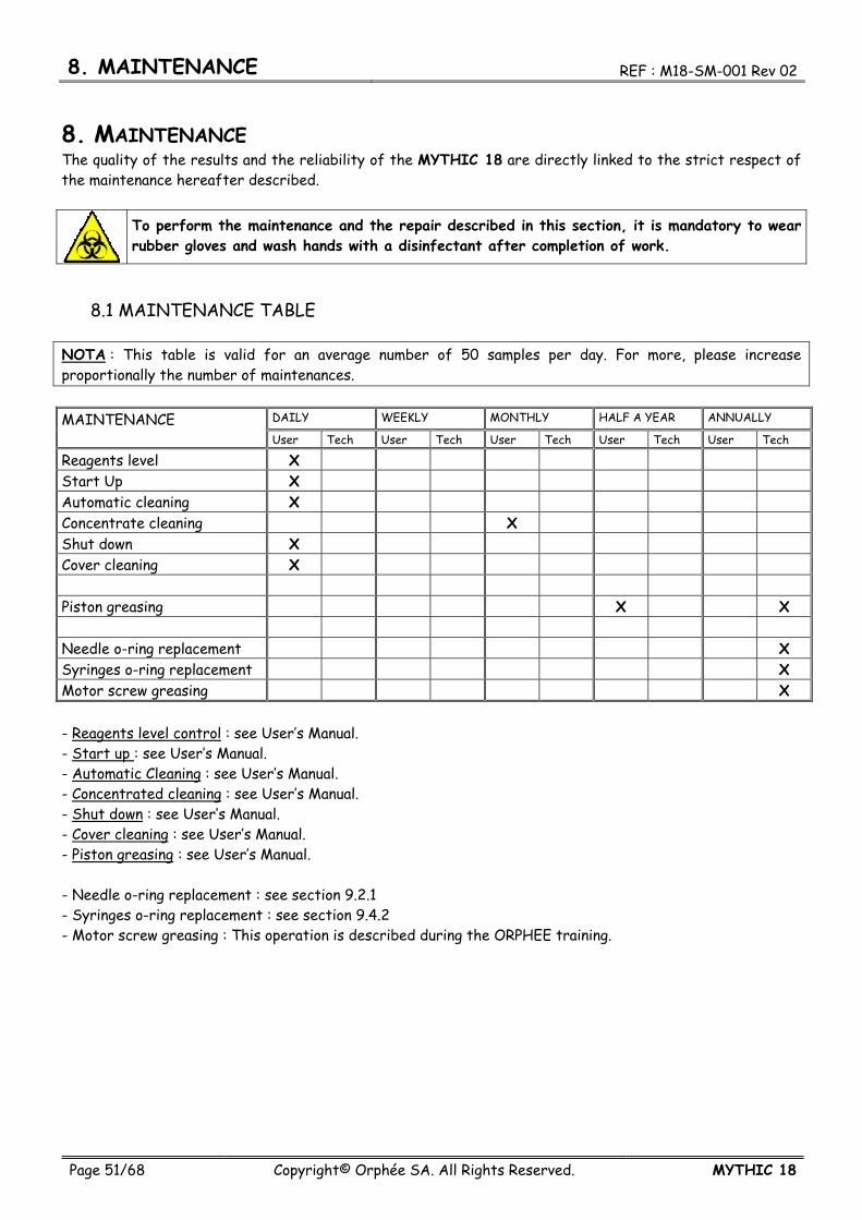
8.1 MAINTENANCE TABLE
NOTA : This table is valid for an average number of 50 samples per day. For more, please increase proportionally the number of maintenances. MAINTENANCE DAILY WEEKLY MONTHLY HALF A YEAR ANNUALLY
User Tech User Tech User Tech User Tech User Tech
Reagents level X Start Up X Automatic cleaning X Concentrate cleaning X Shut down X Cover cleaning X Piston greasing X X Needle o-ring replacement X Syringes o-ring replacement X Motor screw greasing X - Reagents level control : see User’s Manual. - Start up : see User’s Manual. - Automatic Cleaning : see User’s Manual. - Concentrated cleaning : see User’s Manual. - Shut down : see User’s Manual. - Cover cleaning : see User’s Manual. - Piston greasing : see User’s Manual. - Needle o-ring replacement : see section 9.2.1 - Syringes o-ring replacement : see section 9.4.2 - Motor screw greasing : This operation is described during the ORPHEE training.
8. MAINTENANCE REF : M18-SM-001 Rev 02
Page 52/68 Copyright© Orphée SA. All Rights Reserved. MYTHIC 18
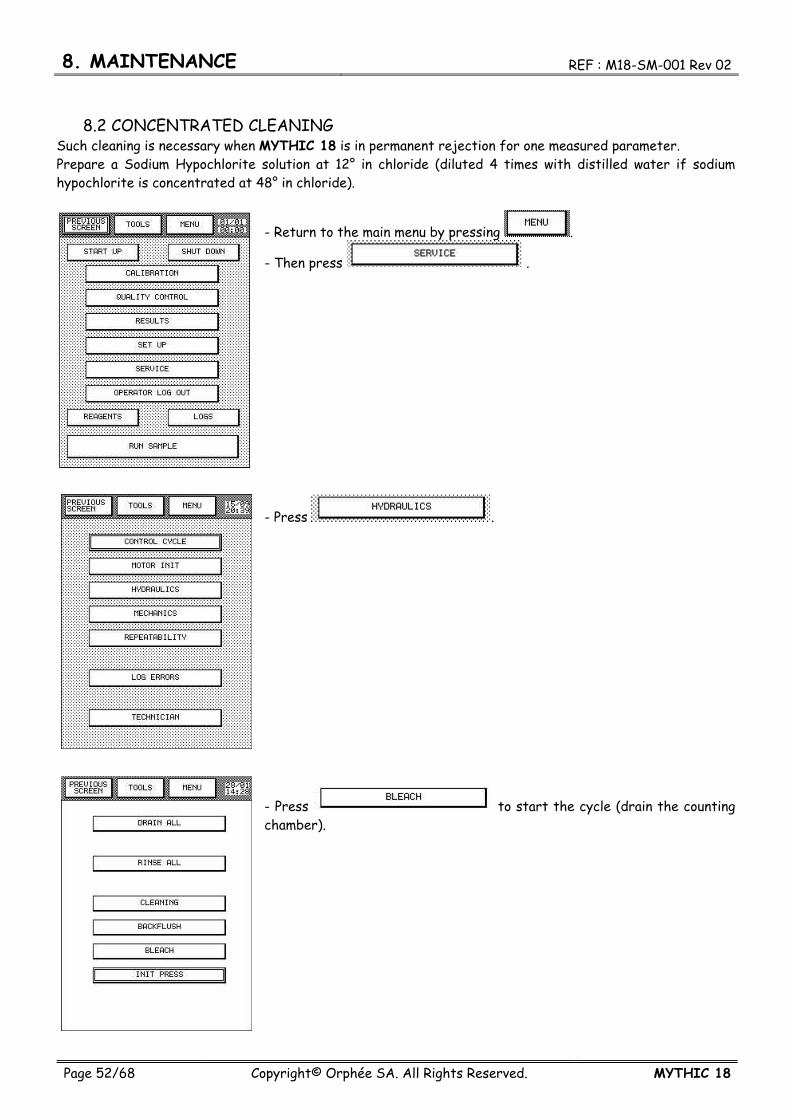
8.2 CONCENTRATED CLEANING Such cleaning is necessary when MYTHIC 18 is in permanent rejection for one measured parameter. Prepare a Sodium Hypochlorite solution at 12° in chloride (diluted 4 times with distilled water if sodium hypochlorite is concentrated at 48° in chloride).
- Return to the main menu by pressing .
- Then press .
- Press .
- Press to start the cycle (drain the counting chamber).

REF : M18-SM-001 Rev 02 8. MAINTENANCE
MYTHIC 18 Copyright© Orphée SA. All Rights Reserved. Page 53/68
- Wait for the information window. - Open the door on the right side (see section 1.1.3). - Put 2 ml of sodium hypochlorite solution in each counting chamber. - Press the button in the window located in the middle of the screen. - MYTHIC 18 performs a maintenance cycle of the apertures followed by a stand by mode during 2 min. - After 2 min. MYTHIC 18 rinses all of the elements. Operator can perform an analytic cycle. -
Wear rubber gloves and wash hands with a disinfectant after completion of work.
8.3 CLEAN OUT This procedure has to be used when the MYTHIC 18 must be transported for a long distance by car, train or plane. This procedure consists of cleaning the MYTHIC 18 with sodium hypochloride, then rinsing it with distilled water and drying it before the transportation.
The clean out is accessible from MAIN SCREEN then SERVICE then TECHNICIAN.
- Press
REF : M18-SM-001 Rev 02 9. REPARING
Page 54/68 Copyright© Orphée SA. All Rights Reserved. MYTHIC 18
9. REPAIRING
For all the following operations wear rubber gloves and wash hands with a disinfectant after completion of work. Be careful with the edge of the metal sheets after having dismantled of the covers.
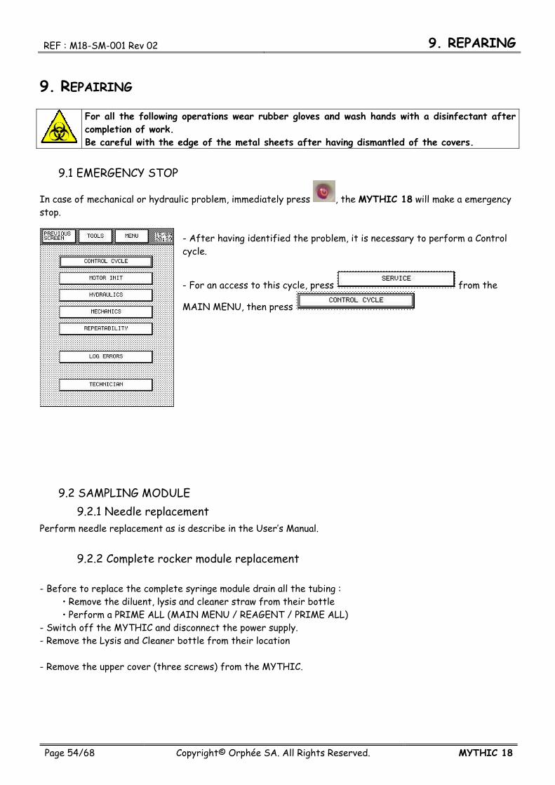
9.1 EMERGENCY STOP
In case of mechanical or hydraulic problem, immediately press , the MYTHIC 18 will make a emergency stop.
- After having identified the problem, it is necessary to perform a Control cycle.
- For an access to this cycle, press from the
MAIN MENU, then press
9.2 SAMPLING MODULE 9.2.1 Needle replacement
Perform needle replacement as is describe in the User’s Manual.
9.2.2 Complete rocker module replacement - Before to replace the complete syringe module drain all the tubing :
Remove the diluent, lysis and cleaner straw from their bottle Perform a PRIME ALL (MAIN MENU / REAGENT / PRIME ALL)
- Switch off the MYTHIC and disconnect the power supply. - Remove the Lysis and Cleaner bottle from their location - Remove the upper cover (three screws) from the MYTHIC.

REF : M18-SM-001 Rev 02 9. REPARING
MYTHIC 18 Copyright© Orphée SA. All Rights Reserved. Page 55/68
- Unscrew the rocker fixation screw but DO NOT remove it. - Unscrew and remove the screw which maintain the IR barrier.
- Disconnect the three tubing and cut the ties. - Unscrew the two guide screw but DO NOT remove it. - Then slide down the guide - Remove the complete rocker module.
REASSEMBLY PROCEDURE : To reassemble the unit, carry out the various operations in the opposite direction.

9. REPARING REF : M18-SM-001 Rev 02
Page 56/68 Copyright© Orphée SA. All Rights Reserved. MYTHIC 18
9.3 COUNTING BATHS MODULE 9.3.1 Baths dismantling
Perform baths dismantling as described in the User’s Manual.
9.3.2 Baths o-ring replacement Perform baths o-ring replacement as described in the User’s Manual.
9.3.3 Aperture block replacement Perform aperture block replacement as described in the User’s Manual.
9.3.4 Complete baths module replacement
- Before to replace the complete syringe module, drain all the tubing :
Remove the diluent, lysis and cleaner straw from their bottle Perform a PRIME ALL (MAIN MENU / REAGENT / PRIME
ALL) - Switch off the MYTHIC and disconnect the power supply. - Remove the Lysis and Cleaner bottle from their location - Then put the MYTHIC on its left side.
Remove the baths connection (HGB, WBC coaxial, RBC coaxial and thermal captor). Unscrew (but WITHOUT dismantle them) the three screws which maintain the baths module (the third screw is located behind the over flow tubing). Cut the fixation ties of the tubing. Disconnect the tubing from the manifold and the bath. Slide up and remove the baths module.
NOTA : Take care about the tubing reconnection, if necessary, cut few millimeters (2 to 3mm) of tubing or exchange them. REASSEMBLY PROCEDURE :To reassemble the unit, carry out the various operations in the opposite direction.

REF : M18-SM-001 Rev 02 9. REPARING
MYTHIC 18 Copyright© Orphée SA. All Rights Reserved. Page 57/68
9.4 SYRINGE MODULE 9.4.1 Piston greasing
Perform the piston greasing as described in the User’s Manual.
9.4.2 O-ring or piston replacement
- Before replacing the complete syringe module, drain all the tubing :
Remove the diluent, lysis and cleaner straw from their bottle Perform a PRIME ALL (MAIN MENU / REAGENT / PRIME
ALL) - Put the syringe in lubrication position (MAIN MENU / SERVICE / MECHANICS / LUBRICATE POS.) - Switch off the MYTHIC and disconnect the power supply. - Remove the Lysis and Cleaner bottle from their location - Then put the MYTHIC on its left side.
- Unscrew (but WITHOUT dismantle them) the four screws which maintain the syringe module. .
- Lift the bloc, to exit the syringe pistons from the piston carriage. - Exchange the piston, if needed.

9. REPARING REF : M18-SM-001 Rev 02
Page 58/68 Copyright© Orphée SA. All Rights Reserved. MYTHIC 18
-.Unscrew and remove the eight screws which maintain the o-ring plate. - Remove the o-ring plate and exchange the o-rings.
REASSEMBLY PROCEDURE :To reassemble the unit, carry out the various operations in the opposite direction.
9.4.3 Complete syringe module replacement Before exchanging the complete syringe module, put the MYTHIC on its left side as describe above (section 9.4.2).
- Disconnect all the valves connection. - Unscrew (but WITHOUT dismantle them) the four screws which maintain the syringe module. - Remove the waste and diluent tubing. - Cut the fixation ties of the tubing. -.Unscrew and remove the screws which maintain the ground fitting. - Disconnect the tubing. - Remove the complete syringe module.
NOTA : Take care about the tubing reconnection, if necessary, cut few millimeters (2 to 4mm) of tubing or exchange them.

REF : M18-SM-001 Rev 02 9. REPARING
MYTHIC 18 Copyright© Orphée SA. All Rights Reserved. Page 59/68
9.5 BOARDS REPLACEMENT
THE THREE BOARDS OF THE MYTHIC 18 ARE VERY SENSITIVE TO ELECTROSTATIC DISCHARGE, YOU HAVE TO USE A BODY EARTH CONNECTION TO HANDLE THE BOARDS FOR THEIR REPLACEMENT OR DISMANTLING.
9.5.1 GUI board replacement
Unscrew (but WITHOUT dismantle them) the two upper screws which maintain the front panel.
Unscrew (but WITHOUT dismantle it) the lower screw which maintain the front panel.

9. REPARING REF : M18-SM-001 Rev 02
Page 60/68 Copyright© Orphée SA. All Rights Reserved. MYTHIC 18
Lift the front panel and then pull it toward the front of the instrument.
VERY CAREFULLY and SLOWLY push on the upper side of the connector, and then push on the lower side to up the fixing system . This part is VERY sensitive. In case of brake, the complete GUI board have to be changed.
VERY SLOWLY pull the flat cable outside the connector.
REF : M18-SM-001 Rev 02 9. REPARING
MYTHIC 18 Copyright© Orphée SA. All Rights Reserved. Page 61/68
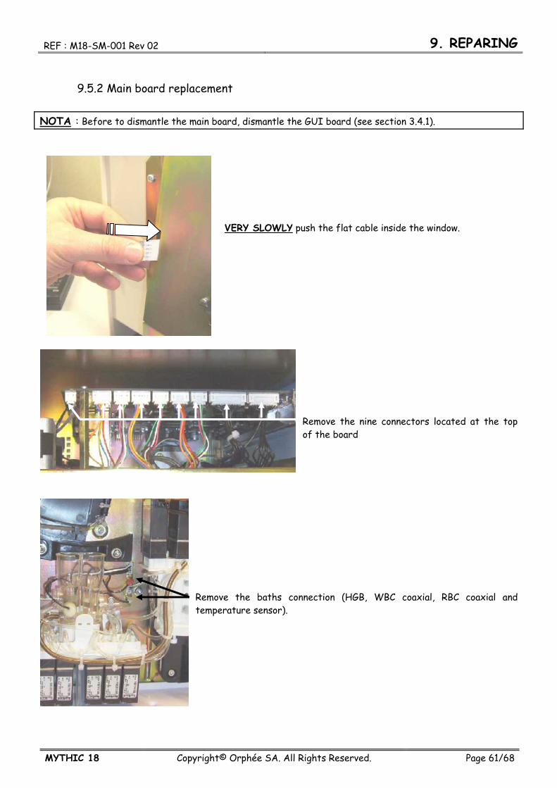
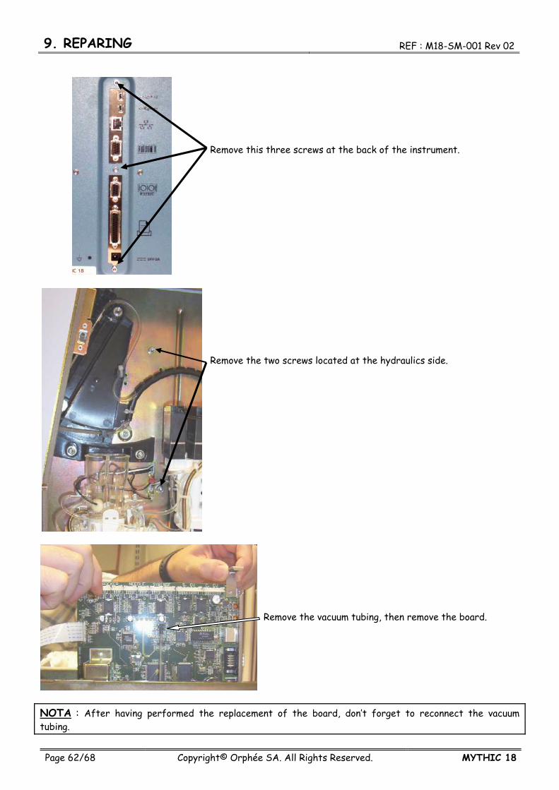
9.5.2 Main board replacement NOTA : Before to dismantle the main board, dismantle the GUI board (see section 3.4.1).
VERY SLOWLY push the flat cable inside the window.
Remove the nine connectors located at the top of the board
Remove the baths connection (HGB, WBC coaxial, RBC coaxial and temperature sensor).
9. REPARING REF : M18-SM-001 Rev 02
Page 62/68 Copyright© Orphée SA. All Rights Reserved. MYTHIC 18
Remove this three screws at the back of the instrument.
Remove the two screws located at the hydraulics side.
Remove the vacuum tubing, then remove the board.
NOTA : After having performed the replacement of the board, don’t forget to reconnect the vacuum tubing.

REF : M18-SM-001 Rev 02 9. REPARING
MYTHIC 18 Copyright© Orphée SA. All Rights Reserved. Page 63/68
9.5.3 Main board 9.5.3.1 Fuse replacement
- This fuse protects the 24v circuit. - Remove the fuse with a thin pliers and replace it by a new one.
- Use a Littelfuse NANO² Slo-Blo fuse model 0454 004 to replace the old one. - It’s strictly forbidden to use an another type of fuse.
9.5.3.2 Battery replacement
- This battery is only used to supply the real time clock. - With a screwdriver lift the clips maintaining the battery. - Slip down the battery to remove it and replace it by a new one.
- Use a Maxell battery model CR2016 to replace the old one. - It’s strictly forbidden to use an another type of battery.
READ CAREFULLY THE FOLLOWING RECOMMENDATIONS.
Handling/storage Never expose the battery to ultrasonic sound. Exposing the battery to ultrasonic sound may cause short-circuiting because the inside material is broken into pieces, leading to distortion, leakage, overheating, explosion, or fire. Never subject the battery to severe shock. Dropping, throwing or stomping on the battery may cause distortion, leakage, overheating, explosion, or fire.
9. REPARING REF : M18-SM-001 Rev 02
Page 64/68 Copyright© Orphée SA. All Rights Reserved. MYTHIC 18
Never short-circuit the battery while installing into equipment. Please be careful when installing the battery not to short-circuit it with metal portions of the equipment. Use the correct battery suitable for the equipment. The battery may not be suitable for the specific equipment due to the using conditions or type of equipment. Please select the suitable battery according to the handling instructions of the equipment. Never use or leave the battery in a hot place such as under the direct rays of the sun or in a car in hot weather. If you do, this may cause distortion, leakage, overheating, explosion, or fire. Never allow the battery to come in contact with water. If it does, this may cause the battery to rust or lead to distortion, leakage, overheating, explosion, or fire. Never store the battery in a hot and highly humid environment. Doing so may cause the performance of the battery to deteriorate. In certain environments, this may lead to distortion, leakage, overheating, explosion, or fire. Disposal The battery may be regulated by national or local regulation. Please follow the instructions of proper regulation. As electric capacity is left in a discarded battery and it comes into contact with other metals, it could lead to distortion, leakage, overheating, or explosion, so make sure to cover the (+) and (-) terminals with friction tape or some other insulator before disposal.

REF : M18-SM-001 Rev 02 9. REPARING
MYTHIC 18 Copyright© Orphée SA. All Rights Reserved. Page 65/68
9.5.4. Preamplifier board replacement NOTA : Before to dismantle the preamplifier board, dismantle the Main board (see section 5.2.1).
Remove the two screws located on the copper side.
Remove the preamplifier box from the main board.
To reassemble the part, carry out the various operations in the opposite direction.
REF : M18-SM-001 Rev 02 10. TROUBLESHOOTING
MYTHIC 18 Copyright© Orphée SA. All Rights Reserved. Page 66/68
10. TROUBLESHOOTING
In any case, if a problem is not solved, call Orphée’s.
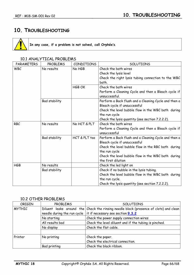
10.1 ANALYTICAL PROBLEMS PARAMETERS PROBLEMS CONDITIONS SOLUTIONS
WBC No results No HGB Check the bath wires Check the lysis level Check the right lysis tubing connection to the WBC bath.
HGB OK Check the bath wires Perform a Cleaning Cycle and then a Bleach cycle if unsuccessful.
Bad stability Perform a Back flush and a Cleaning Cycle and then a Bleach cycle if unsuccessful Check the level bubble flow in the WBC bath during the run cycle Check the lysis quantity (see section 7.2.2.2).
RBC No results No HCT & PLT Check the bath wires Perform a Cleaning Cycle and then a Bleach cycle if unsuccessful
Bad stability HCT & PLT too Perform a Back flush and a Cleaning Cycle and then a Bleach cycle if unsuccessful Check the level bubble flow in the RBC bath during the run cycle Check the level bubble flow in the WBC bath during the first dilution
HGB No results Check the led light on Bad stability Check if no bubble in the lysis tubing.
Check the level bubble flow in the WBC bath during the run cycle. Check the lysis quantity (see section 7.2.2.2).
10.2 OTHER PROBLEMS ORIGIN PROBLEMS SOLUTIONS
MYTHIC Diluent leaks around the needle during the run cycle
Check the rinsing needle block (presence of clots) and clean it if necessary see section 9.3.2
No starting Check the power supply connection wires All results bad Check the level diluent and if the tubing is pinched. No display Check the flat cable. Printer No printing Check the paper.
Check the electrical connection. Bad printing Check the black ribbon.

REF : M18-SM-001 Rev 02 10. TROUBLESHOOTING
MYTHIC 18 Copyright© Orphée SA. All Rights Reserved. Page 67/68
10.3 TROUBLESHOOTING MESSAGE This section allows to know what to do when a troubleshooting message appears on the screen.
MESSAGE ACTION
BACKUP : BAD FOLDER DUPLICATION Re-start the Mythic.
BACKUP : CALIBRATION HISTORY IS FULL Delete the calibration results.
BACKUP : FOLDER NOT FOUND Re-start the Mythic.
BACKUP : MEMORY IS ALMOST FULL. PLEASE DELETE RESULTS Delete results
BACKUP : NO MEMORY AVAILABLE FOR STORAGE Delete the stored results.
BACKUP : QC HISTORY IS FULL Delete the Q.C. results of the ongoing lot.
BACKUP : REPEATABILITY HISTORY IS FULL Delete the repeatability results.
BACKUP: FILE SYSTEM FAILED Re-start the Mythic.
BACKUP: LAST QC RESTORED. File has been restored to previous state
BACKUP: LAST RESULTS RESTORED. File has been restored to previous state
BACKUP: LAST SETUP RESTORED. Indicate that your SETUP has been restored
BACKUP: PARTIAL CALI. RES. DELETED. A bad Result storage happened
BACKUP: PARTIAL NUM DELETED. A bad Result storage happened
BACKUP: PARTIAL QC RES. DELETED. A bad Result storage happened
BACKUP: PARTIAL REPET. RES. DELETED. A bad Result storage happened
BACKUP: SECTOR FAILED hardware failure on memory
BACKUP: SETUP UPDATED WITH DEFAULT VALUES. Indicate that your SETUP has been released
BACKUP: SYSTEM ERROR Re-start the Mythic.
CLEAN NOT DONE Perform a rinse cycle.
CLEANER ALMOST EMPTY Replace the bottle and perform a prime Cleaner
COM: CRC CONTROL ERROR Communication error retry
CONTROL CYCLE NOT DONE Perform a control cycle.
CYCLE : BUSY Wait before performing a cycle.
CYCLE : CMD VALVE FAILED Change the valve
CYCLE : EMERGENCY STOP Perform a control cycle.
CYCLE : INIT NOT DONE Perform an initialization or a control cycle.
CYCLE : VALVE XX FAILED Change the valve
CYCLE STOPPED BY USER Emergency stop, please perform a control cycle.
CYCLE: DOOR OPENED Close the door.
CYCLE: PRESSURE DEFAULT Check the valve 8 and the pressure sensor tubing
DILUENT ALMOST EMPTY Replace the container and perform a prime Diluent
HARDWARE: SYSTEM ERROR Re-start the Mythic.
ID AND/OR PID MANDATORY ( CHECK SETUP). SID ALWAYS MANDATORYEnter an ID and/or PID and SID
INIT PRINTER Switch on the printer or invalidate the printings.
INTERN : COUNT ERROR Re-start the Mythic.
INTERN: MEMORY CORRUPTED Re-start the Mythic.
INTERN: NO MEMORY AVAILABLE Re-start the Mythic.
INTERN: RESULT AREA IS LOCKED Wait before performing a cycle. If persisting, re-start the Mythic.
LYSE ALMOST EMPTY Replace the bottle and perform a prime Lysis

10. TROUBLESHOOTING REF : M18-SM-001 Rev 02
Page 68/68 Copyright© Orphée SA. All Rights Reserved. MYTHIC 18
MESSAGE ACTION
MECA : HOME ROCKER NOT FOUND Perform an INIT MOTOR or a CONTROL CYCLE.
MECA : HOME NEEDLE NOT FOUND Perform an INIT MOTOR or a CONTROL CYCLE. MECA : HOME SYRINGE NOT FOUND Perform an INIT MOTOR or a CONTROL CYCLE. MECA : MOTOR NEEDLE GAP Nothing.
MECA : MOTOR ROCKER GAP Nothing.
MECA : MOTOR SYRINGE GAP Nothing.
MECA : NEEDLE NOT IN TOP POSITION Perform a CONTROL CYCLE.
MECA: MOTOR NEEDLE BUSY Re-start the Mythic.
MECA: MOTOR ROCKER BUSY Re-start the Mythic.
MECA: MOTOR SYRINGE BUSY Re-start the Mythic.
NO PRINTER RESPONSE Switch on the printer or invalidate the printings.
NO PRINTER RESPONSE Switch on the printer or invalidate the printings.
NO PRINTER SELECTED Switch on the printer or invalidate the printings.
OUT OF RANGE Modify the value
PRINTER ERROR Switch on the printer or invalidate the printings.
PRINTER IS BUSY Switch on the printer or invalidate the printings.
PRINTER IS OFF Switch on the printer or invalidate the printings.
PRINTER: NO PAPER Add some paper.
RINSE NOT DONE Perform a RINSE ALL cycle.
RS232: ACK ERROR Re-start the Mythic.
RS232: INTERNAL ERROR Re-start the Mythic.
RS232: SYNCHRO ERROR Re-start the Mythic.
RS232: TIME OUT Re-start the Mythic.
RUNNING AUTO CLEANING , Press OK.
START UP CYCLE FAILED Perform a new start up cycle
START UP CYCLE NOT DONE Perform a start up cycle.
SVM: BAD VERSION. Update the SVM software
SVM: COM. TIME OUT Re-start the SVM.
SVM: ILLEGAL SERIAL NUMBER. This MYTHIC can not be connected to the SVM
SVM: UNMATCH Re-enter the file or confirm it (manual connection on the SVM).
SVM: WG Westgard alarm.
SVM: XB XB alarm.
SYSTEM : EEPROM COM ERROR Re-start the Mythic.
SYSTEM : INTERNAL TIME OUT Re-start the Mythic.
SYSTEM: FATAL ERROR Re-start the Mythic.
THE CLEANER USED IS OUT OF DATE Replace the bottle and perform a prime Cleaner
THE DILUENT USED IS OUT OF DATE Replace the container and perform a prime Diluent
THE LYSE USED IS OUT OF DATE Replace the bottle and perform a prime Lysis
WASTE ALMOST FULL Replace the waste container