n registers and counters n complex sequential circuits sequential circuit design read mk 309-315,...
TRANSCRIPT

Registers and CountersComplex Sequential Circuits
Sequential Circuit Design
Read MK 309-315, 326-339
5.2 - Jon Turner - 04/19/23
Controller
PC Data Bus
Address Bus
Memory
0000000100020003000400050006000700080009000a
ffff
. . .
IR IAR ACC
read/writeALU
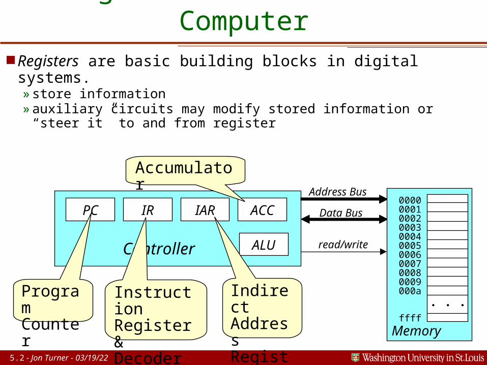
Registers in the Basic Computer Registers are basic building blocks in digital systems.
»store information»auxiliary circuits may modify stored information or “steer it”
to and from register
ProgramCounter
Instruction Register & Decoder
Indirect Address Register
Accumulator
5.3 - Jon Turner - 04/19/23
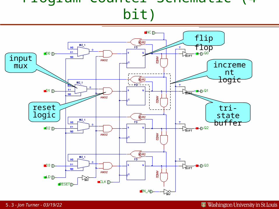
Program Counter Schematic (4 bit)
flip flop
inputmux increme
ntlogic
tri-statebuffer
resetlogic
5.4 - Jon Turner - 04/19/23
Registers and Counters A register is a set of flip flops, often supplemented by
additional circuits to control input and output.»can have parallel I/O or serial I/O or combination
Usually, registers are used to store a set of related bits.»bits that collectively represent an integer value»bits of an ASCII character code»status bits for a device in a computer system (disk controller)
Counters are registers that store numeric values along with circuits to increment/decrement the stored value.»up-counters, down-counters, up-down counters»generalized counters
– BCD counters, gray-code counters, ...

5.5 - Jon Turner - 04/19/23
Simple Parallel Load Register Four bit register.
» if LD is high when clock rises, new values are stored
»LD should change only while CLK is high
Registers using gated clocks can lead to timing problems.» increases clock skew»may lead to violations of flip
flop setup, hold time specs»extra care needed to ensure
correct operation»safer to avoid clock gating
whenever possible

5.6 - Jon Turner - 04/19/23
Preferred Parallel Load Register Multiplexor for each
register bit.»new value loaded when LD
is high»otherwise, old value stored
No gated clock, minimizing clock skew.»simplifies checking of
setup and hold time specs.»can focus on delays
between connected flip flops
Increases gate count by about 30%.
5.7 - Jon Turner - 04/19/23
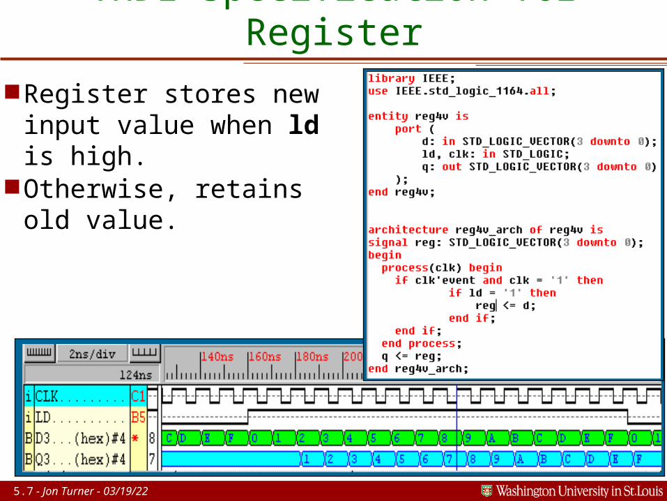
VHDL Specification for Register Register stores new
input value when ld is high.
Otherwise, retains old value.
5.8 - Jon Turner - 04/19/23
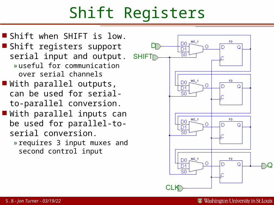
Shift Registers Shift when SHIFT is low. Shift registers support
serial input and output.»useful for communication
over serial channels With parallel outputs,
can be used for serial-to-parallel conversion.
With parallel inputs can be used for parallel-to-serial conversion.» requires 3 input muxes
and second control input

5.9 - Jon Turner - 04/19/23
VHDL for Bidirectional Shift Register ld enables loading.
» if sl asserted then left shift» else if sr asserted then
right» else parallel load

5.10 - Jon Turner - 04/19/23
Synchronous Ripple Carry Counter Change in low order bit can
affect carry in all higher bits. No problem, so long as carry
stable by next rising clock edge. Can be too slow for counters with
many bits.
5.11 - Jon Turner - 04/19/23
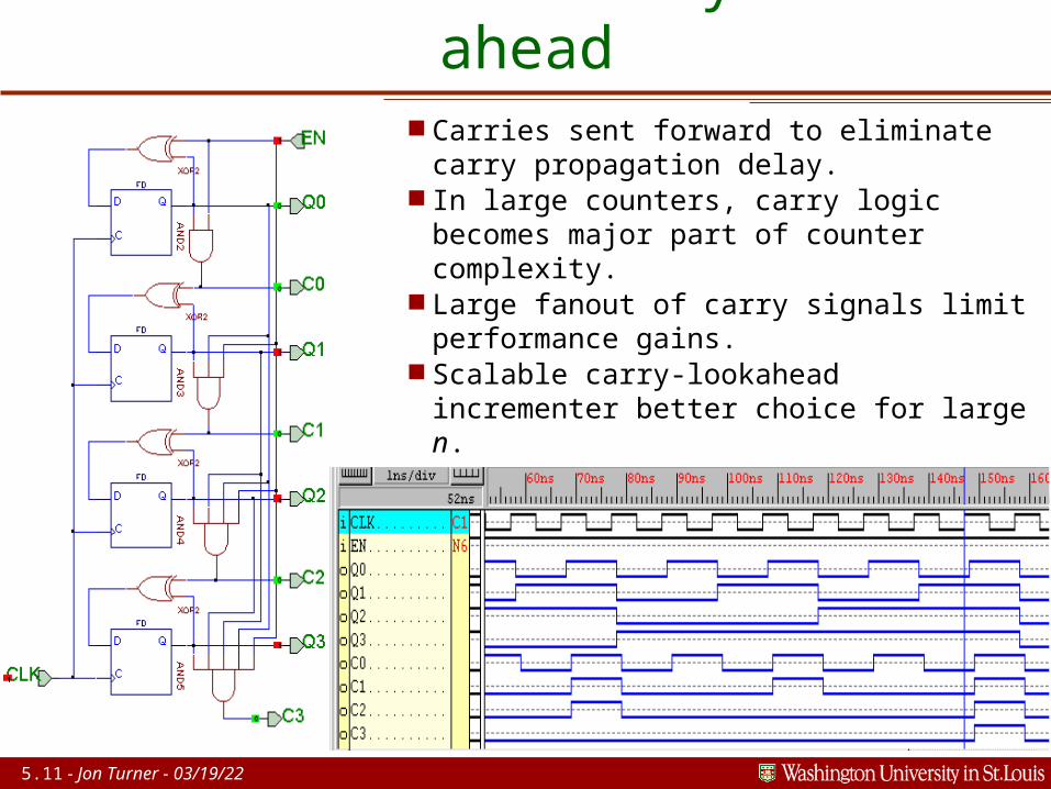
Counter with Carry Look-ahead Carries sent forward to eliminate
carry propagation delay. In large counters, carry logic
becomes major part of counter complexity.
Large fanout of carry signals limit performance gains.
Scalable carry-lookahead incrementer better choice for large n.
5.12 - Jon Turner - 04/19/23
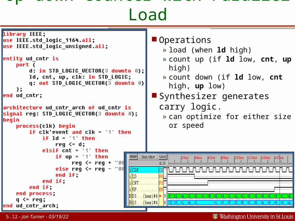
Up-down Counter with Parallel Load
Operations» load (when ld high)» count up (if ld low, cnt, up high)» count down (if ld low, cnt high, up low)
Synthesizer generates carry logic.» can optimize for either size
or speed
5.13 - Jon Turner - 04/19/23
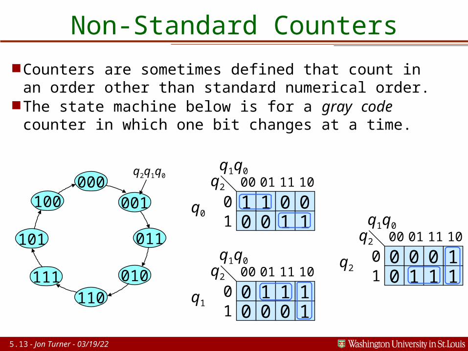
Non-Standard Counters
Counters are sometimes defined that count in an order other than standard numerical order.
The state machine below is for a gray code counter in which one bit changes at a time.
1q2
0 01
00 01
0 1
q1q0
01 1
011 10
q0
0q2
0 01
00 01
0 1
q1q0
10 1
111 10
q1
0q2
0 10
00 01
0 1
q1q0
01 1
111 10
q2
000
101
110
011
001100
111 010
q2q1q0
5.14 - Jon Turner - 04/19/23
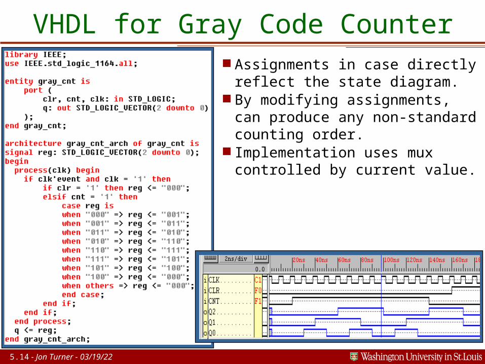
VHDL for Gray Code Counter Assignments in case directly
reflect the state diagram. By modifying assignments,
can produce any non-standard counting order.
Implementation uses mux controlled by current value.
5.15 - Jon Turner - 04/19/23
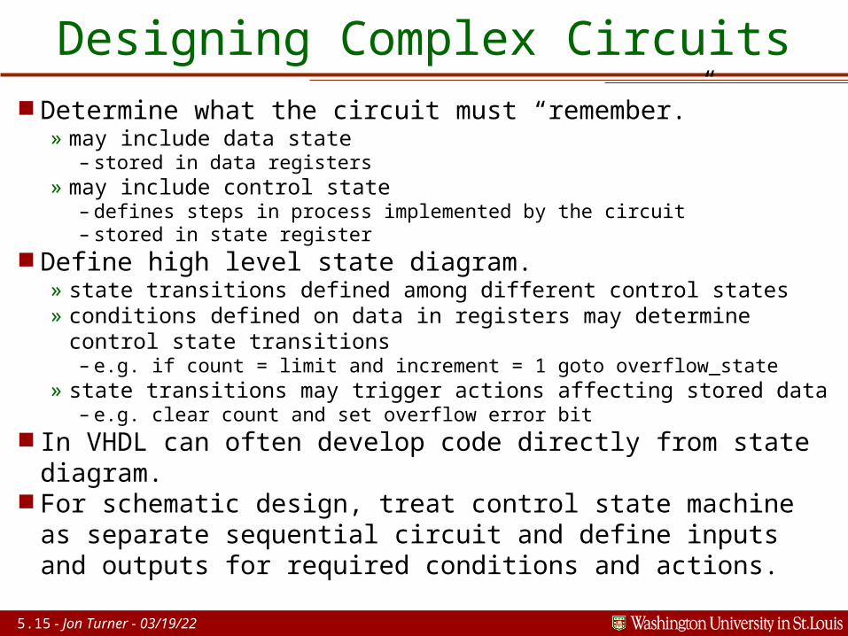
Designing Complex Circuits Determine what the circuit must “remember.”
» may include data state– stored in data registers
» may include control state– defines steps in process implemented by the circuit– stored in state register
Define high level state diagram.» state transitions defined among different control states» conditions defined on data in registers may determine control
state transitions– e.g. if count = limit and increment = 1 goto overflow_state
» state transitions may trigger actions affecting stored data– e.g. clear count and set overflow error bit
In VHDL can often develop code directly from state diagram.
For schematic design, treat control state machine as separate sequential circuit and define inputs and outputs for required conditions and actions.
5.16 - Jon Turner - 04/19/23
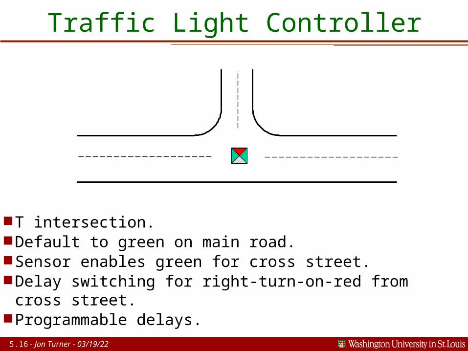
Traffic Light Controller
T intersection. Default to green on main road. Sensor enables green for cross street. Delay switching for right-turn-on-red from cross
street. Programmable delays.
5.17 - Jon Turner - 04/19/23
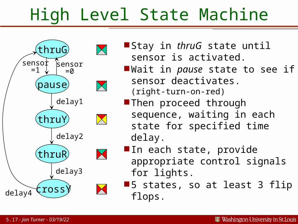
High Level State Machine
Stay in thruG state until sensor is activated.
Wait in pause state to see if sensor deactivates.(right-turn-on-red)
Then proceed through sequence, waiting in each state for specified time delay.
In each state, provide appropriate control signals for lights.
5 states, so at least 3 flip flops.
thruG
pause
thruY
thruR
crossY
sensor=1
sensor=0
delay1
delay4
delay2
delay3
5.18 - Jon Turner - 04/19/23
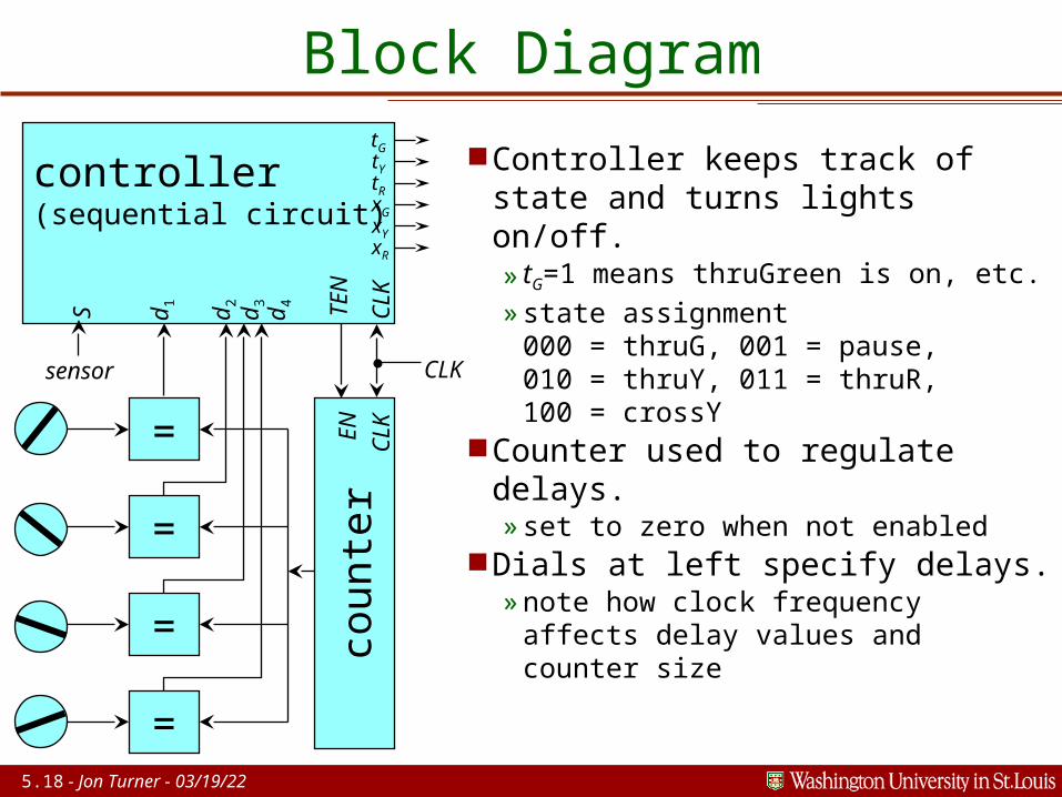
Block Diagram
Controller keeps track of state and turns lights on/off.» tG=1 means thruGreen is on,
etc.»state assignment
000 = thruG, 001 = pause,010 = thruY, 011 = thruR,100 = crossY
Counter used to regulate delays.»set to zero when not enabled
Dials at left specify delays.»note how clock frequency
affects delay values and counter size
controller(sequential circuit)
cou
nte
r
=
=
=
d1
d2
d3
d4 TEN
EN
CLK
CLK
CLK
tG tY tR xG xY xR
=
S
sensor
5.19 - Jon Turner - 04/19/23
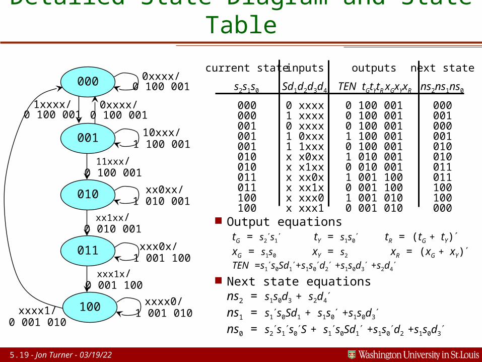
Detailed State Diagram and State Table
current state
s2s1s0 000000001001001010010011011100100
inputs
Sd1d2d3d4 0 xxxx1 xxxx0 xxxx1 0xxx1 1xxxx x0xxx x1xxx xx0xx xx1xx xxx0x xxx1
outputs
TEN tGtYtR xGxYxR 0 100 0010 100 0010 100 0011 100 0010 100 0011 010 0010 010 0011 001 1000 001 1001 001 0100 001 010
next state
ns2ns1ns0 000001000001010010011011100100000
1xxxx/0 100 001
0xxxx/0 100 001
0xxxx/0 100 001
10xxx/1 100 001
xx0xx/ 1 010 001
xxx0x/ 1 001 100
xxxx0/1 001 010xxxx1/
0 001 010
000
001
010
011
100
11xxx/0 100 001
xx1xx/0 010 001
xxx1x/0 001 100
Output equationstG = s2s1 tY = s1s0 tR = (tG + tY)xG = s1s0 xY = s2 xR = (xG + xY)TEN =s1s0Sd1+s1s0d2 +s1s0d3 +s2d4
Next state equationsns2 = s1s0d3 + s2d4
ns1 = s1s0Sd1 + s1s0 +s1s0d3
ns0 = s2s1s0S + s1s0Sd1 +s1s0d2 +s1s0d3

5.20 - Jon Turner - 04/19/23
Schematic for Traffic Light Controller
timer
comparators
input delaysfrom switches
statemachine
5.21 - Jon Turner - 04/19/23
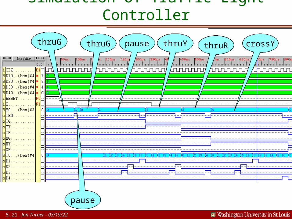
Simulation of Traffic Light Controller
thruG thruG
pause
pause thruY thruR crossY
5.22 - Jon Turner - 04/19/23
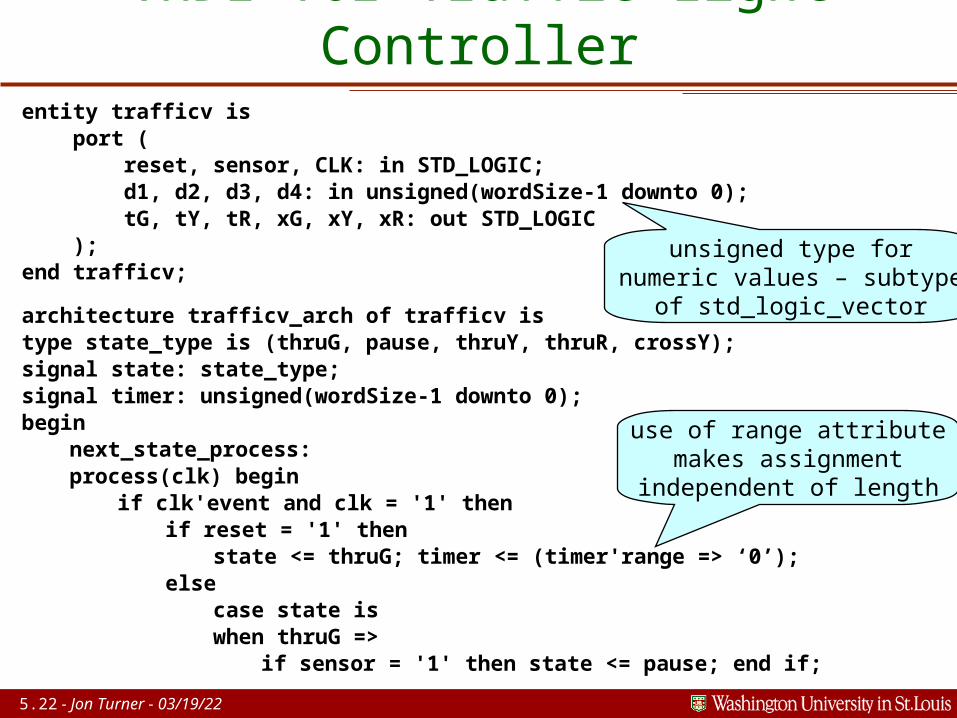
VHDL for Traffic Light Controllerentity trafficv is port ( reset, sensor, CLK: in STD_LOGIC; d1, d2, d3, d4: in unsigned(wordSize-1 downto 0); tG, tY, tR, xG, xY, xR: out STD_LOGIC );end trafficv;
architecture trafficv_arch of trafficv istype state_type is (thruG, pause, thruY, thruR, crossY);signal state: state_type;signal timer: unsigned(wordSize-1 downto 0);begin
next_state_process:process(clk) begin
if clk'event and clk = '1' thenif reset = '1' then
state <= thruG; timer <= (timer'range => ‘0’);else
case state iswhen thruG =>
if sensor = '1' then state <= pause; end if;
use of range attributemakes assignment
independent of length
unsigned type fornumeric values – subtype
of std_logic_vector
5.23 - Jon Turner - 04/19/23
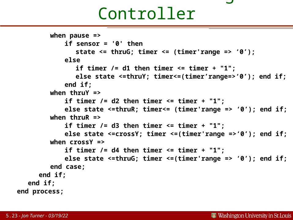
VHDL for Traffic Light Controllerwhen pause =>
if sensor = '0' thenstate <= thruG; timer <= (timer'range => ‘0’);
elseif timer /= d1 then timer <= timer + "1";else state <=thruY; timer<=(timer’range=>‘0’); end if;
end if;when thruY =>
if timer /= d2 then timer <= timer + "1";else state <=thruR; timer<= (timer'range => ‘0’); end if;
when thruR =>if timer /= d3 then timer <= timer + "1";else state <=crossY; timer <=(timer'range =>‘0’); end if;
when crossY =>if timer /= d4 then timer <= timer + "1";else state <=thruG; timer <=(timer'range => ‘0’); end if;
end case;end if;
end if;end process;
5.24 - Jon Turner - 04/19/23
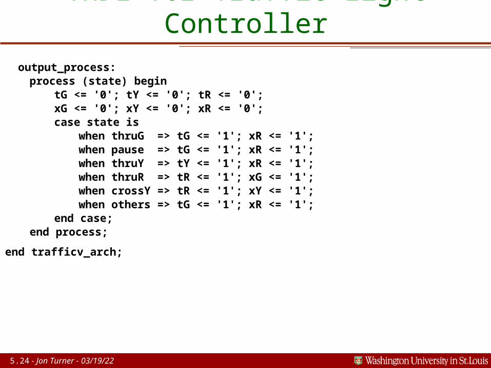
VHDL for Traffic Light Controller output_process:
process (state) begintG <= '0'; tY <= '0'; tR <= '0';xG <= '0'; xY <= '0'; xR <= '0';case state is
when thruG => tG <= '1'; xR <= '1';when pause => tG <= '1'; xR <= '1';when thruY => tY <= '1'; xR <= '1';when thruR => tR <= '1'; xG <= '1';when crossY => tR <= '1'; xY <= '1';when others => tG <= '1'; xR <= '1';
end case;end process;
end trafficv_arch;
5.25 - Jon Turner - 04/19/23
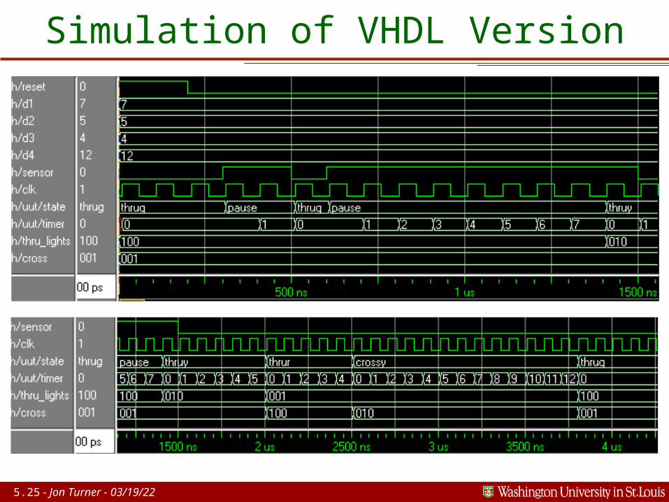
Simulation of VHDL Version
5.26 - Jon Turner - 04/19/23
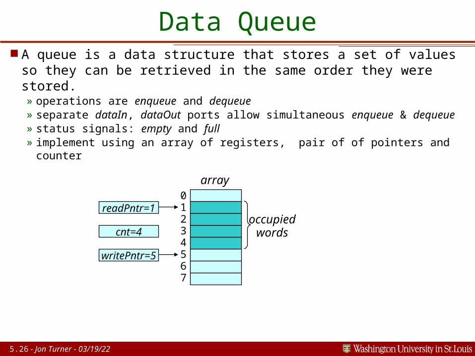
Data Queue A queue is a data structure that stores a set of values so they
can be retrieved in the same order they were stored.» operations are enqueue and dequeue» separate dataIn, dataOut ports allow simultaneous enqueue & dequeue» status signals: empty and full» implement using an array of registers, pair of of pointers and counter
readPntr=1
cnt=4
writePntr=5
01234567
occupiedwords
array
5.27 - Jon Turner - 04/19/23
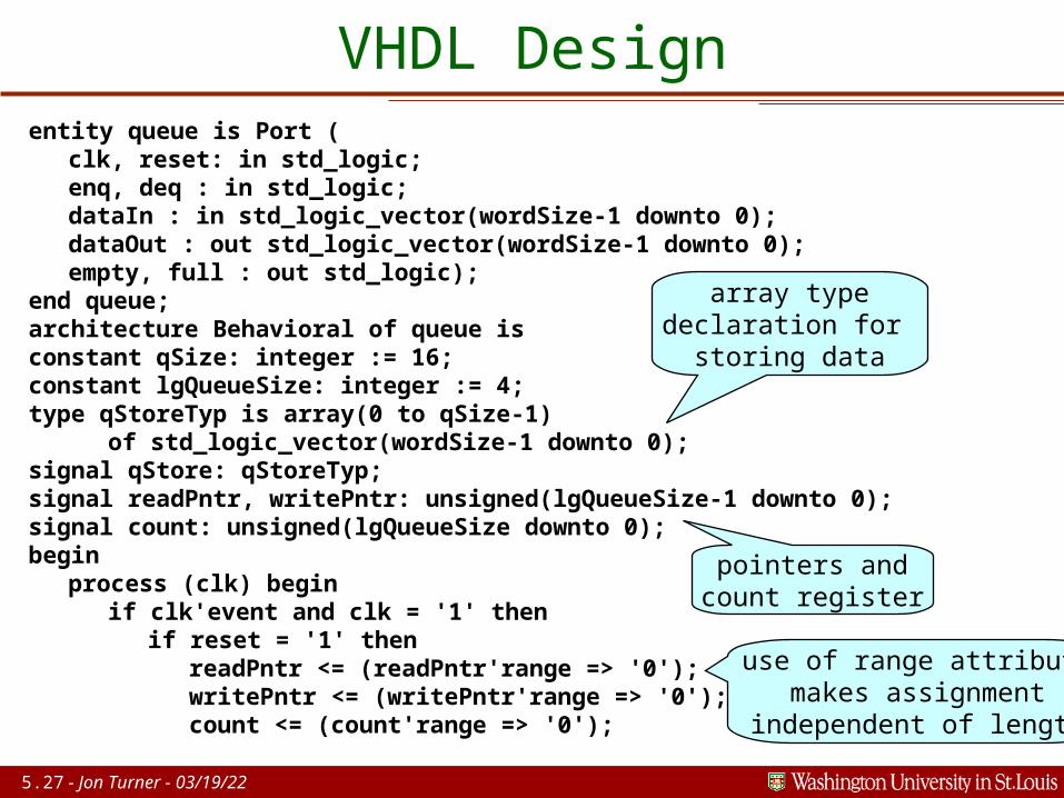
VHDL Designentity queue is Port (
clk, reset: in std_logic;enq, deq : in std_logic;dataIn : in std_logic_vector(wordSize-1 downto 0);dataOut : out std_logic_vector(wordSize-1 downto 0);empty, full : out std_logic);
end queue;architecture Behavioral of queue isconstant qSize: integer := 16;constant lgQueueSize: integer := 4;type qStoreTyp is array(0 to qSize-1)
of std_logic_vector(wordSize-1 downto 0);signal qStore: qStoreTyp;signal readPntr, writePntr: unsigned(lgQueueSize-1 downto 0);signal count: unsigned(lgQueueSize downto 0);begin
process (clk) beginif clk'event and clk = '1' then
if reset = '1' thenreadPntr <= (readPntr'range => '0');writePntr <= (writePntr'range => '0'); count <= (count'range => '0');
array typedeclaration for
storing data
pointers andcount register
use of range attributemakes assignment
independent of length
5.28 - Jon Turner - 04/19/23
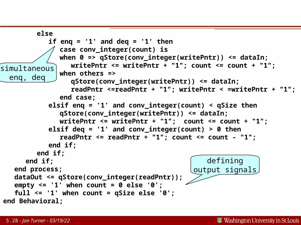
elseif enq = '1' and deq = '1' then
case conv_integer(count) iswhen 0 => qStore(conv_integer(writePntr)) <= dataIn;
writePntr <= writePntr + "1"; count <= count + "1";when others =>
qStore(conv_integer(writePntr)) <= dataIn;readPntr <=readPntr + "1"; writePntr < =writePntr + "1";
end case;elsif enq = '1' and conv_integer(count) < qSize then
qStore(conv_integer(writePntr)) <= dataIn;writePntr <= writePntr + "1"; count <= count + "1";
elsif deq = '1' and conv_integer(count) > 0 thenreadPntr <= readPntr + "1"; count <= count - "1";
end if;end if;
end if;end process;dataOut <= qStore(conv_integer(readPntr));empty <= '1' when count = 0 else '0';full <= '1' when count = qSize else '0';
end Behavioral;
simultaneousenq, deq
definingoutput signals

5.29 - Jon Turner - 04/19/23
Simulation Results
5.30 - Jon Turner - 04/19/23
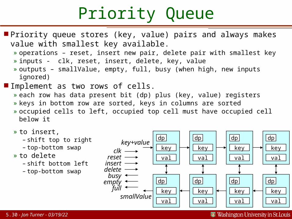
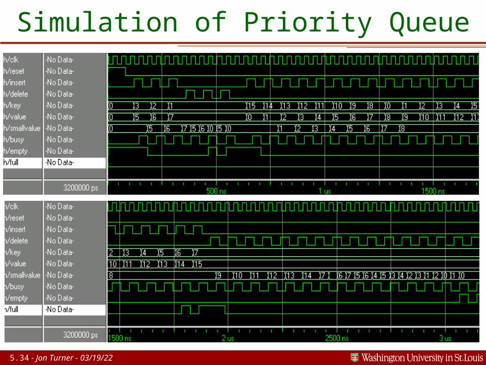
Priority Queue Priority queue stores (key, value) pairs and always makes
value with smallest key available.» operations – reset, insert new pair, delete pair with smallest key» inputs - clk, reset, insert, delete, key, value» outputs – smallValue, empty, full, busy (when high, new inputs ignored)
Implement as two rows of cells.» each row has data present bit (dp) plus (key, value) registers» keys in bottom row are sorted, keys in columns are sorted» occupied cells to left, occupied top cell must have occupied cell below
it» to insert,
– shift top to right– top-bottom swap
» to delete– shift bottom left– top-bottom swap
key
val
dp
key
val
dp
key
val
dp
key
val
dp
key
val
dp
key
val
dp
key
val
dp
key
val
dp
clkresetinsertdelete
busyempty
full
key+value
smallValue
5.31 - Jon Turner - 04/19/23
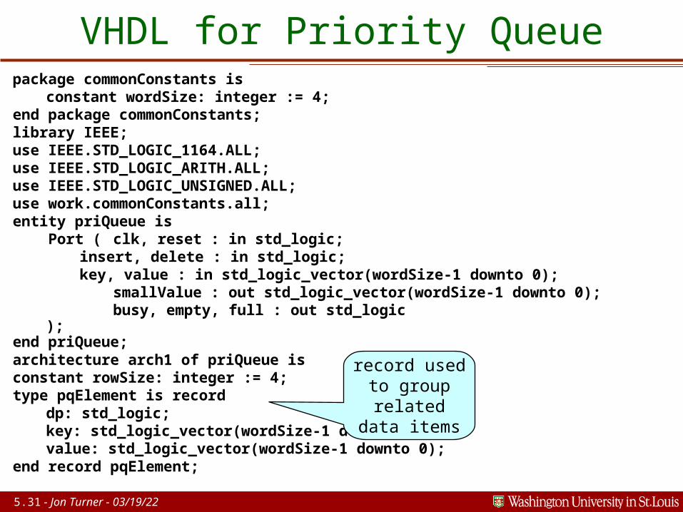
VHDL for Priority Queuepackage commonConstants is
constant wordSize: integer := 4;end package commonConstants;library IEEE;use IEEE.STD_LOGIC_1164.ALL;use IEEE.STD_LOGIC_ARITH.ALL;use IEEE.STD_LOGIC_UNSIGNED.ALL;use work.commonConstants.all;entity priQueue is Port ( clk, reset : in std_logic;
insert, delete : in std_logic; key, value : in std_logic_vector(wordSize-1 downto 0);
smallValue : out std_logic_vector(wordSize-1 downto 0); busy, empty, full : out std_logic
);end priQueue;architecture arch1 of priQueue isconstant rowSize: integer := 4;type pqElement is record
dp: std_logic; key: std_logic_vector(wordSize-1 downto 0);value: std_logic_vector(wordSize-1 downto 0);
end record pqElement;
record used to group
related data items

5.32 - Jon Turner - 04/19/23
type rowTyp is array(0 to rowSize-1) of pqElement;signal top, bot: rowTyp;type state_type is (ready, inserting, deleting);signal state: state_type;begin
process(clk) beginif clk'event and clk = '1' then
if reset = '1' thenfor i in 0 to rowSize-1 loop
top(i).dp <= '0'; bot(i).dp <= '0';end loop;state <= ready;
elsif state = ready and insert = '1' thenif top(rowSize-1).dp /= '1' then
for i in 1 to rowSize-1 looptop(i) <= top(i-1);
end loop;top(0) <= ('1',key,value);state <= inserting;
end if;
arrays of records
implement two rows
make all slots empty initially
shift top row right

5.33 - Jon Turner - 04/19/23
elsif state = ready and delete = '1' thenif bot(0).dp /= '0' then
for i in 0 to rowSize-2 loopbot(i) <= bot(i+1);
end loop;bot(rowSize-1).dp <= '0'; state <= deleting;
end if;elsif state = inserting or state = deleting then
for i in 0 to rowSize-1 loopif top(i).dp = '1' and
(top(i).key < bot(i).key or bot(i).dp = '0') thenbot(i) <= top(i); top(i) <= bot(i);
end if; end loop;
state <= ready;end if;
end if;end process;smallValue <= bot(0).value when bot(0).dp = '1' else
(smallValue’range => '0');empty <= not bot(0).dp;full <= top(rowSize-1).dp;busy <= '1' when state /= ready else '0';
end arch1;
shift bottom row left
compare and swap columns
output signal definitions
(all synchronous)
5.34 - Jon Turner - 04/19/23
Simulation of Priority Queue
5.35 - Jon Turner - 04/19/23
Metastability Most synchronous systems have asynchronous inputs.
»keyboard input on a computer,»sensor on a traffic light controller,»card insertion on an ATM, etc.
Asynchronous inputs change at unpredictable times.»so, can change during clock transition, causing metastability
Output of a metastable flip flop can oscillate or remain at intermediate value causing unpredictable behavior in other flip flops.»metastability usually ends quickly, but no definite time limit»so, circuit failures due to metastability are unavoidable»however, systems can be designed to make failures rare
5.36 - Jon Turner - 04/19/23
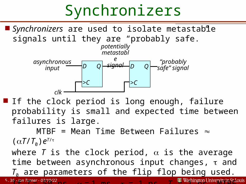
Synchronizers Synchronizers are used to isolate metastable
signals until they are “probably safe.”
D Q
>C
D Q
>C
clk
asynchronousinput
potentially
metastable
signal“probably
safe” signal
If the clock period is long enough, failure probability is small and expected time between failures is large.
MTBF = Mean Time Between Failures (T/T0)eT/
where T is the clock period, is the average time between asynchronous input changes, and T0 are parameters of the flip flop being used.
If T = 50 ns, = 1 ms, = 1 ns, T0 = 1 ns, MTBF 8 trillion years, if T = 10 ns, MTBF becomes 220 seconds!