n - remove/install/overhaul - tradebit · pdf filen - remove/install/overhaul 1991 mazda miata...
TRANSCRIPT
N - REMOVE/INSTALL/OVERHAUL
1991 Mazda Miata
1991 ENGINE PERFORMANCE Removal, Overhaul & Installation
B2200, B2600i, Miata, MPV, MX-6, Navajo, Protege, RX7, 323, 626, 929
INTRODUCTION
Removal, overhaul and installation procedures are covered inthis article. If component removal and installation is primarily anunbolt and bolt-on procedure, only a torque specification may befurnished. See TORQUE SPECIFICATIONS TABLE at end of article. On Miata, obtain code number and deactivate anti-theft alarmbefore disconnecting battery cable.
DISTRIBUTOR IGNITION SYSTEM
NOTE: Miata, Navajo and RX7 are equipped with distributorless ignition system.
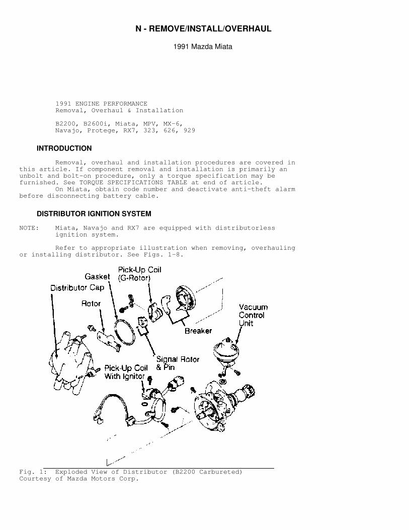
Refer to appropriate illustration when removing, overhaulingor installing distributor. See Figs. 1-8.
Fig. 1: Exploded View of Distributor (B2200 Carbureted)Courtesy of Mazda Motors Corp.
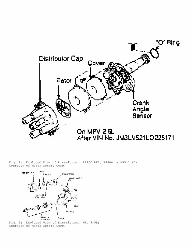
Fig. 2: Exploded View of Distributor (B2200 PFI, B2600i & MPV 2.6L)Courtesy of Mazda Motors Corp.
Fig. 3: Exploded View of Distributor (MPV 3.0L)Courtesy of Mazda Motors Corp.
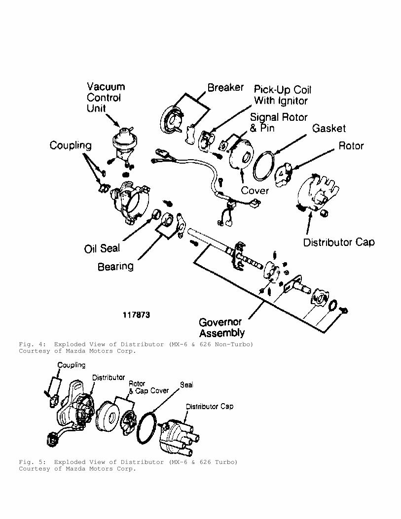
Fig. 4: Exploded View of Distributor (MX-6 & 626 Non-Turbo)Courtesy of Mazda Motors Corp.
Fig. 5: Exploded View of Distributor (MX-6 & 626 Turbo)Courtesy of Mazda Motors Corp.
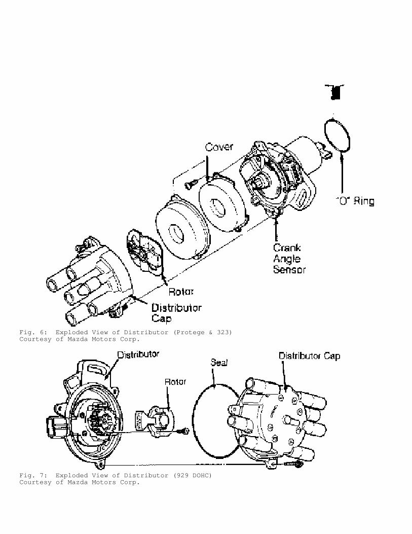
Fig. 6: Exploded View of Distributor (Protege & 323)Courtesy of Mazda Motors Corp.
Fig. 7: Exploded View of Distributor (929 DOHC)Courtesy of Mazda Motors Corp.
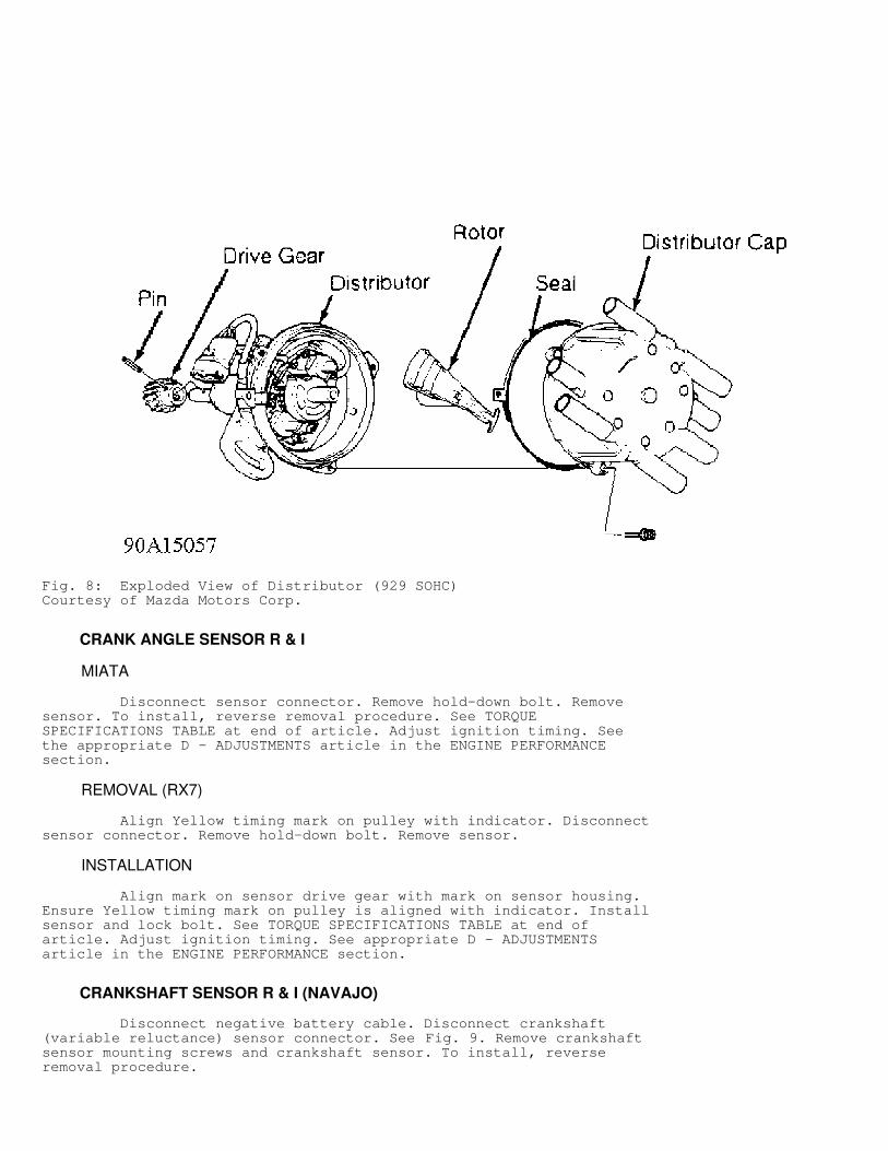
Fig. 8: Exploded View of Distributor (929 SOHC)Courtesy of Mazda Motors Corp.
CRANK ANGLE SENSOR R & I
MIATA
Disconnect sensor connector. Remove hold-down bolt. Removesensor. To install, reverse removal procedure. See TORQUESPECIFICATIONS TABLE at end of article. Adjust ignition timing. Seethe appropriate D - ADJUSTMENTS article in the ENGINE PERFORMANCEsection.
REMOVAL (RX7)
Align Yellow timing mark on pulley with indicator. Disconnectsensor connector. Remove hold-down bolt. Remove sensor.
INSTALLATION
Align mark on sensor drive gear with mark on sensor housing.Ensure Yellow timing mark on pulley is aligned with indicator. Installsensor and lock bolt. See TORQUE SPECIFICATIONS TABLE at end ofarticle. Adjust ignition timing. See appropriate D - ADJUSTMENTSarticle in the ENGINE PERFORMANCE section.
CRANKSHAFT SENSOR R & I (NAVAJO)
Disconnect negative battery cable. Disconnect crankshaft(variable reluctance) sensor connector. See Fig. 9. Remove crankshaftsensor mounting screws and crankshaft sensor. To install, reverseremoval procedure.
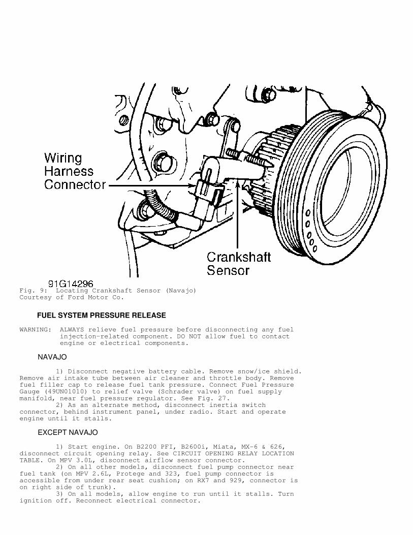
Fig. 9: Locating Crankshaft Sensor (Navajo)Courtesy of Ford Motor Co.
FUEL SYSTEM PRESSURE RELEASE
WARNING: ALWAYS relieve fuel pressure before disconnecting any fuel injection-related component. DO NOT allow fuel to contact engine or electrical components.
NAVAJO
1) Disconnect negative battery cable. Remove snow/ice shield.Remove air intake tube between air cleaner and throttle body. Removefuel filler cap to release fuel tank pressure. Connect Fuel PressureGauge (49UN01010) to relief valve (Schrader valve) on fuel supplymanifold, near fuel pressure regulator. See Fig. 27. 2) As an alternate method, disconnect inertia switchconnector, behind instrument panel, under radio. Start and operateengine until it stalls.
EXCEPT NAVAJO
1) Start engine. On B2200 PFI, B2600i, Miata, MX-6 & 626,disconnect circuit opening relay. See CIRCUIT OPENING RELAY LOCATIONTABLE. On MPV 3.0L, disconnect airflow sensor connector. 2) On all other models, disconnect fuel pump connector nearfuel tank (on MPV 2.6L, Protege and 323, fuel pump connector isaccessible from under rear seat cushion; on RX7 and 929, connector ison right side of trunk). 3) On all models, allow engine to run until it stalls. Turnignition off. Reconnect electrical connector.
CIRCUIT OPENING RELAY LOCATION TABLE�����������������������������������������������������������������������������������������������������������������������
Application Location
B2200 PFI & B2600i ............... Behind Left Kick Panel.Miata ........................ To Left Of Steering Column.MX-6 & 626 .............. Near Fuse Block, On Relay Panel.�����������������������������������������������������������������������������������������������������������������������
FUEL LINE CONNECTORS (NAVAJO)
NOTE: Although push-connect fittings and spring lock couplers are similar in function, different procedures and tools are used to disconnect and connect these connectors. To identify type of connector, see Figs. 10 and 11.
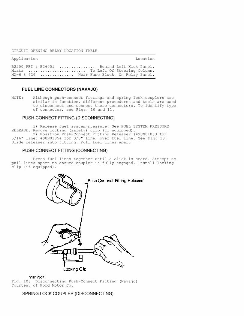
PUSH-CONNECT FITTING (DISCONNECTING)
1) Release fuel system pressure. See FUEL SYSTEM PRESSURERELEASE. Remove locking (safety) clip (if equipped). 2) Position Push-Connect Fitting Releaser (49UN01053 for5/16" line; 49UN01054 for 3/8" line) over fuel line. See Fig. 10.Slide releaser into fitting. Pull fuel lines apart.
PUSH-CONNECT FITTING (CONNECTING)
Press fuel lines together until a click is heard. Attempt topull lines apart to ensure coupler is fully engaged. Install lockingclip (if equipped).
Fig. 10: Disconnecting Push-Connect Fitting (Navajo)Courtesy of Ford Motor Co.
SPRING LOCK COUPLER (DISCONNECTING)
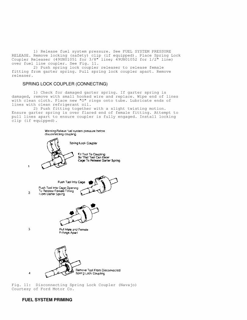
1) Release fuel system pressure. See FUEL SYSTEM PRESSURERELEASE. Remove locking (safety) clip (if equipped). Place Spring LockCoupler Releaser (49UN01051 for 3/8" line; 49UN01052 for 1/2" line)over fuel line coupler. See Fig. 11. 2) Push spring lock coupler releaser to release femalefitting from garter spring. Pull spring lock coupler apart. Removereleaser.
SPRING LOCK COUPLER (CONNECTING)
1) Check for damaged garter spring. If garter spring isdamaged, remove with small hooked wire and replace. Wipe end of lineswith clean cloth. Place new "O" rings onto tube. Lubricate ends oflines with clean refrigerant oil. 2) Push fitting together with a slight twisting motion.Ensure garter spring is over flared end of female fitting. Attempt topull lines apart to ensure coupler is fully engaged. Install lockingclip (if equipped).
Fig. 11: Disconnecting Spring Lock Coupler (Navajo)Courtesy of Ford Motor Co.
FUEL SYSTEM PRIMING
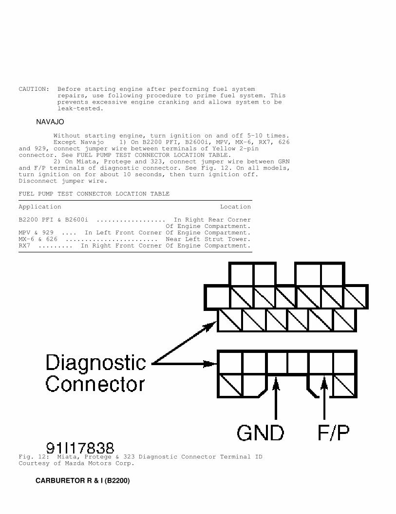
CAUTION: Before starting engine after performing fuel system repairs, use following procedure to prime fuel system. This prevents excessive engine cranking and allows system to be leak-tested.
NAVAJO
Without starting engine, turn ignition on and off 5-10 times. Except Navajo 1) On B2200 PFI, B2600i, MPV, MX-6, RX7, 626and 929, connect jumper wire between terminals of Yellow 2-pinconnector. See FUEL PUMP TEST CONNECTOR LOCATION TABLE. 2) On Miata, Protege and 323, connect jumper wire between GRNand F/P terminals of diagnostic connector. See Fig. 12. On all models,turn ignition on for about 10 seconds, then turn ignition off.Disconnect jumper wire.
FUEL PUMP TEST CONNECTOR LOCATION TABLE�����������������������������������������������������������������������������������������������������������������������
Application Location
B2200 PFI & B2600i .................. In Right Rear Corner Of Engine Compartment.MPV & 929 .... In Left Front Corner Of Engine Compartment.MX-6 & 626 ........................ Near Left Strut Tower.RX7 ......... In Right Front Corner Of Engine Compartment.�����������������������������������������������������������������������������������������������������������������������
Fig. 12: Miata, Protege & 323 Diagnostic Connector Terminal IDCourtesy of Mazda Motors Corp.
CARBURETOR R & I (B2200)
Disconnect negative battery cable. Remove air cleaner.Disconnect accelerator cable, cruise control cable (if equipped), allnecessary vacuum hoses, fuel hoses and electrical connectors. Removecarburetor mounting nuts. Remove carburetor. To install, reverseremoval procedure.
DISASSEMBLY (AIR HORN & CHOKE ASSEMBLY)
1) DO NOT remove choke valve and shaft from air horn.Disconnect vacuum hose from choke opener (pull-off) diaphragm. Removeaccelerator pump connecting rod, spring and lever. See Fig. 17.Disconnect air vent solenoid valve wire from connector. 2) Disconnect choke rod. Remove air horn retaining bolts.Remove air horn and choke assembly from main body. Remove air ventsolenoid valve, spring and gasket from air horn.
DISASSEMBLY (NEEDLE VALVE & FLOAT)
Remove float, pin and gasket. See Figs. 16 and 17. Removeneedle valve assembly. Remove sight glass assembly from main body.
CAUTION: Note location and size of air bleeds and jets before removal. Components must be installed in correct location.
DISASSEMBLY (AIR BLEEDS & JETS)
1) Remove secondary slow jet, secondary slow bleed, secondarymain bleed and secondary main jet from main body. See Figs. 13 and 17.Remove primary main bleed, slow jet and plug, primary slow bleed andprimary main jet from main body. 2) Remove richer air bleed, primary slow bleed, coastingricher air bleed and coasting richer jet from air horn. See Figs. 14and 17.
DISASSEMBLY (MAIN BODY)
1) DO NOT remove venturis from main body. Remove coastingricher solenoid valve and "O" ring. See Fig. 17. Remove idle switchand spring. Remove slow fuel-cut solenoid valve, needle valve, springand gasket. Remove dashpot (M/T). 2) Remove accelerator pump plunger and spring assembly.Remove retaining clip, strainer and inlet check ball. Remove outletcheck ball plug, outlet check ball and spring. 3) Disconnect throttle link, vacuum diaphragm connecting rodand throttle return spring. Remove throttle body-to-main bodyretaining bolts (one bolt is located inside throttle body). Separatethrottle body from main body.
DISASSEMBLY (THROTTLE BODY)
DO NOT remove throttle valve and shaft from throttle body.Remove vacuum (secondary) diaphragm assembly. Remove diaphragm coverscrews. Remove cover, spring and diaphragm. Using small punch andhammer, remove spring pin located in front of mixture adjusting screw.Remove mixture adjusting screw.
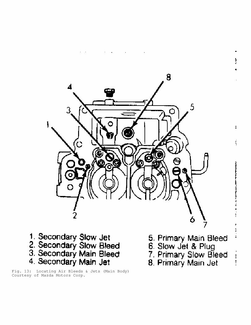
Fig. 13: Locating Air Bleeds & Jets (Main Body)Courtesy of Mazda Motors Corp.
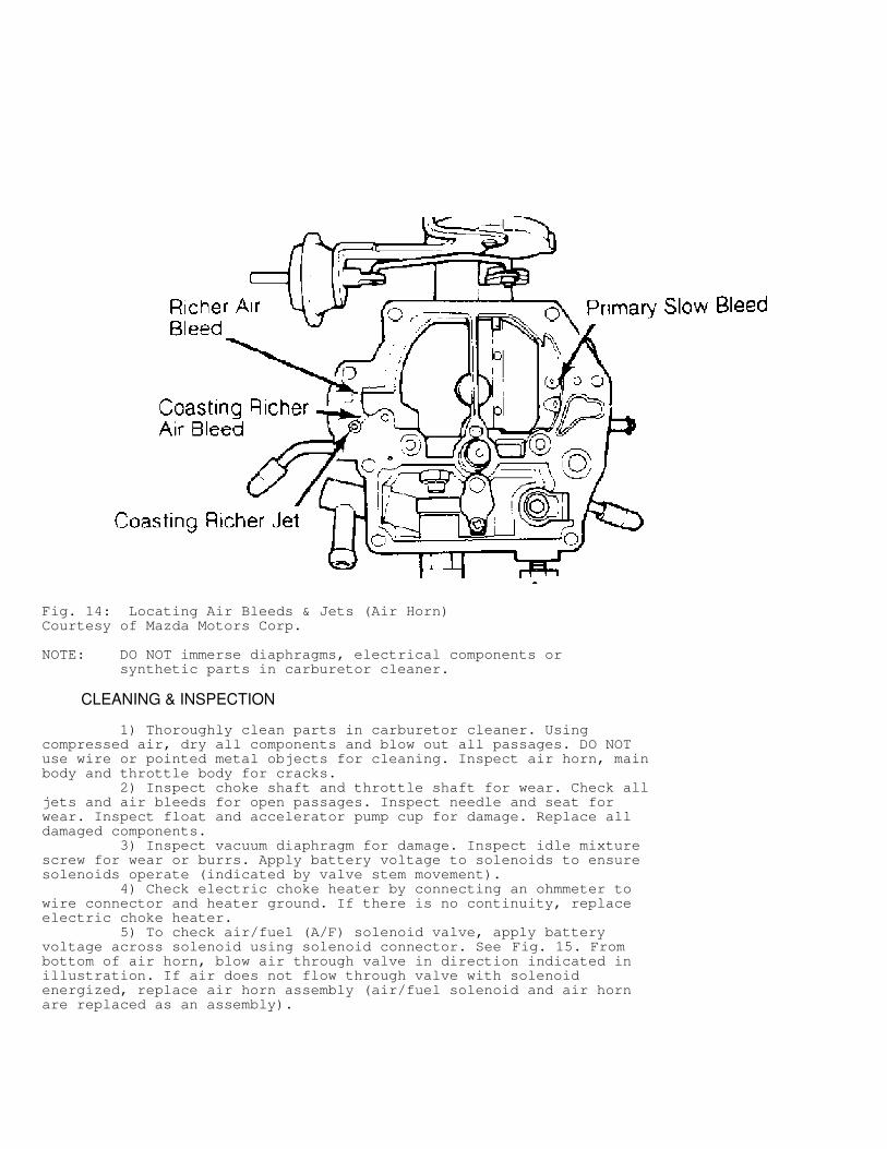
Fig. 14: Locating Air Bleeds & Jets (Air Horn)Courtesy of Mazda Motors Corp.
NOTE: DO NOT immerse diaphragms, electrical components or synthetic parts in carburetor cleaner.
CLEANING & INSPECTION
1) Thoroughly clean parts in carburetor cleaner. Usingcompressed air, dry all components and blow out all passages. DO NOTuse wire or pointed metal objects for cleaning. Inspect air horn, mainbody and throttle body for cracks. 2) Inspect choke shaft and throttle shaft for wear. Check alljets and air bleeds for open passages. Inspect needle and seat forwear. Inspect float and accelerator pump cup for damage. Replace alldamaged components. 3) Inspect vacuum diaphragm for damage. Inspect idle mixturescrew for wear or burrs. Apply battery voltage to solenoids to ensuresolenoids operate (indicated by valve stem movement). 4) Check electric choke heater by connecting an ohmmeter towire connector and heater ground. If there is no continuity, replaceelectric choke heater. 5) To check air/fuel (A/F) solenoid valve, apply batteryvoltage across solenoid using solenoid connector. See Fig. 15. Frombottom of air horn, blow air through valve in direction indicated inillustration. If air does not flow through valve with solenoidenergized, replace air horn assembly (air/fuel solenoid and air hornare replaced as an assembly).
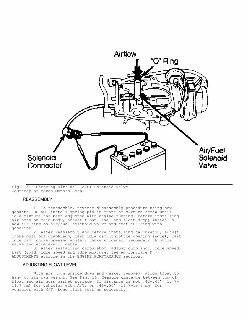
Fig. 15: Checking Air/Fuel (A/F) Solenoid ValveCourtesy of Mazda Motors Corp.
REASSEMBLY
1) To reassemble, reverse disassembly procedure using newgaskets. DO NOT install spring pin in front of mixture screw untilidle mixture has been adjusted with engine running. Before installingair horn on main body, adjust float level and float drop; install anew "O" ring on air/fuel solenoid valve and coat "O" ring withgasoline. 2) After reassembly and before installing carburetor, adjustchoke pull-off diaphragm, fast idle cam (throttle opening angle), fastidle cam (choke opening angle), choke unloader, secondary throttlevalve and accelerator cable. 3) After installing carburetor, adjust curb (hot) idle speed,fast (cold) idle speed and idle mixture. See appropriate D -ADJUSTMENTS article in the ENGINE PERFORMANCE section..
ADJUSTING FLOAT LEVEL
With air horn upside down and gasket removed, allow float tohang by its own weight. See Fig. 16. Measure distance between top offloat and air horn gasket surface. If distance is not .42-.46" (10.7-11.7 mm) for vehicles with A/T, or .46-.50" (11.7-12.7 mm) forvehicles with M/T, bend float seat as necessary.
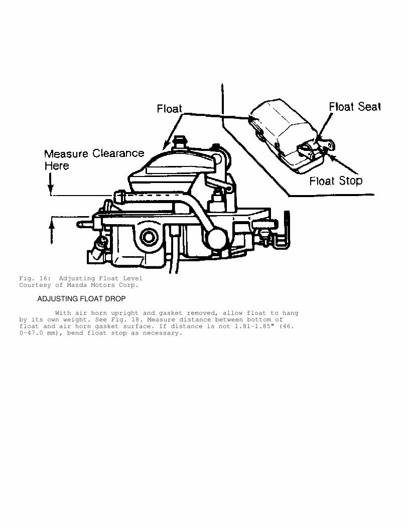
Fig. 16: Adjusting Float LevelCourtesy of Mazda Motors Corp.
ADJUSTING FLOAT DROP
With air horn upright and gasket removed, allow float to hangby its own weight. See Fig. 18. Measure distance between bottom offloat and air horn gasket surface. If distance is not 1.81-1.85" (46.0-47.0 mm), bend float stop as necessary.
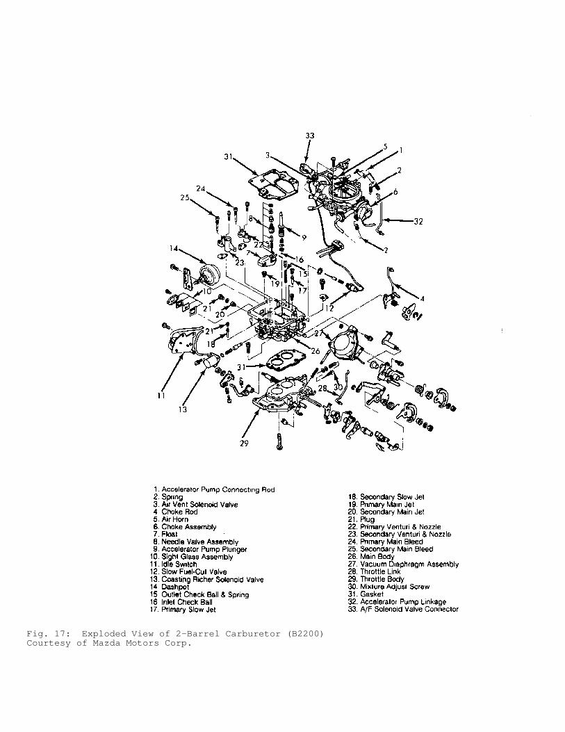
Fig. 17: Exploded View of 2-Barrel Carburetor (B2200)Courtesy of Mazda Motors Corp.
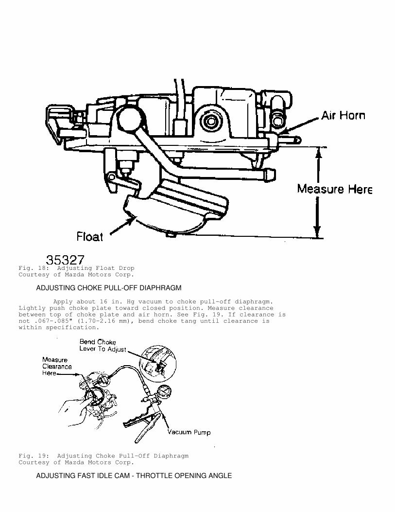
Fig. 18: Adjusting Float DropCourtesy of Mazda Motors Corp.
ADJUSTING CHOKE PULL-OFF DIAPHRAGM
Apply about 16 in. Hg vacuum to choke pull-off diaphragm.Lightly push choke plate toward closed position. Measure clearancebetween top of choke plate and air horn. See Fig. 19. If clearance isnot .067-.085" (1.70-2.16 mm), bend choke tang until clearance iswithin specification.
Fig. 19: Adjusting Choke Pull-Off DiaphragmCourtesy of Mazda Motors Corp.
ADJUSTING FAST IDLE CAM - THROTTLE OPENING ANGLE
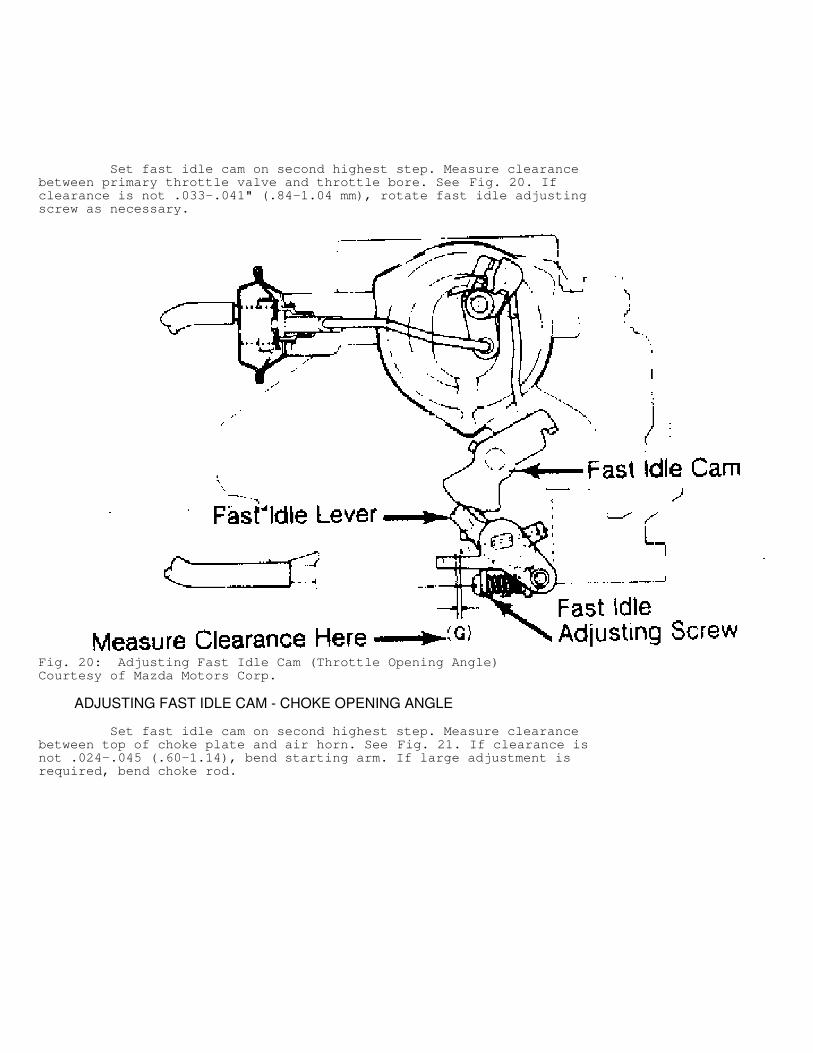
Set fast idle cam on second highest step. Measure clearancebetween primary throttle valve and throttle bore. See Fig. 20. Ifclearance is not .033-.041" (.84-1.04 mm), rotate fast idle adjustingscrew as necessary.
Fig. 20: Adjusting Fast Idle Cam (Throttle Opening Angle)Courtesy of Mazda Motors Corp.
ADJUSTING FAST IDLE CAM - CHOKE OPENING ANGLE
Set fast idle cam on second highest step. Measure clearancebetween top of choke plate and air horn. See Fig. 21. If clearance isnot .024-.045 (.60-1.14), bend starting arm. If large adjustment isrequired, bend choke rod.
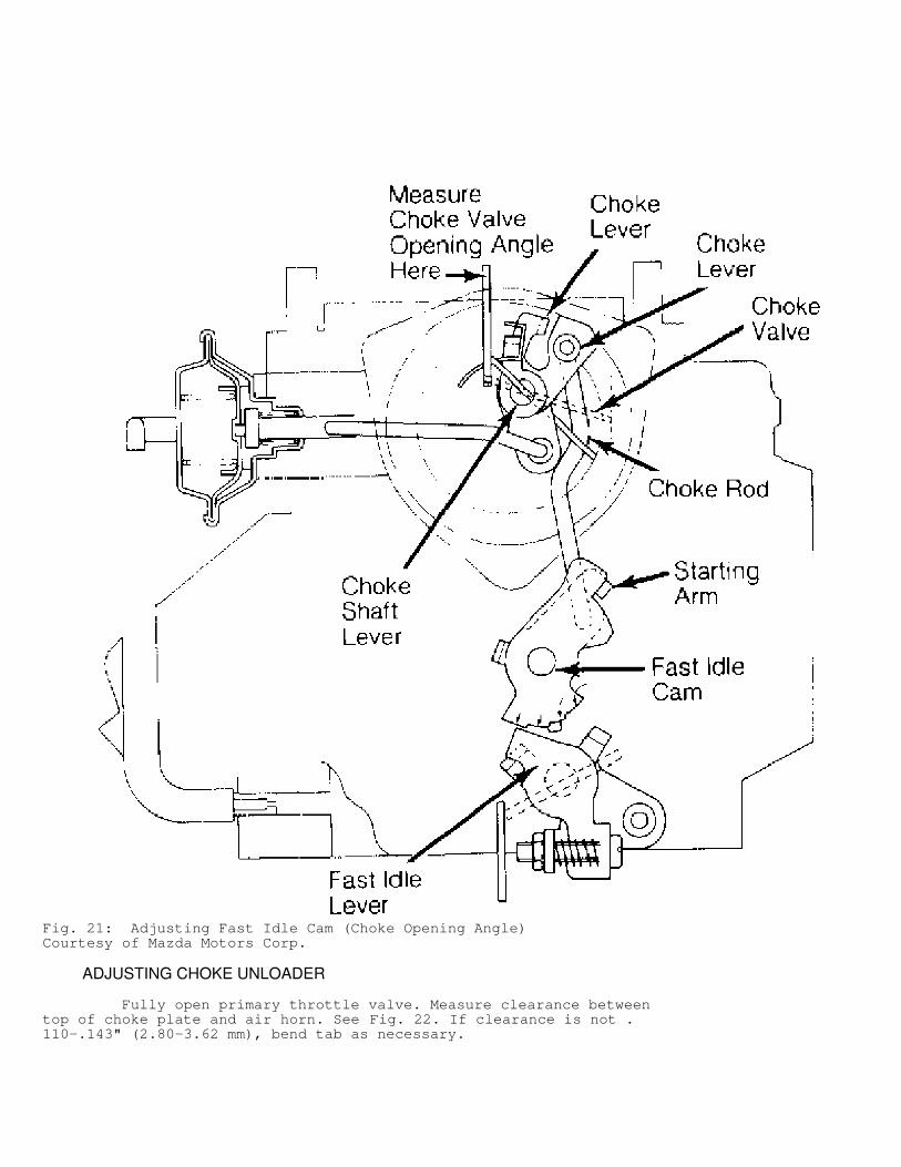
Fig. 21: Adjusting Fast Idle Cam (Choke Opening Angle)Courtesy of Mazda Motors Corp.
ADJUSTING CHOKE UNLOADER
Fully open primary throttle valve. Measure clearance betweentop of choke plate and air horn. See Fig. 22. If clearance is not .110-.143" (2.80-3.62 mm), bend tab as necessary.
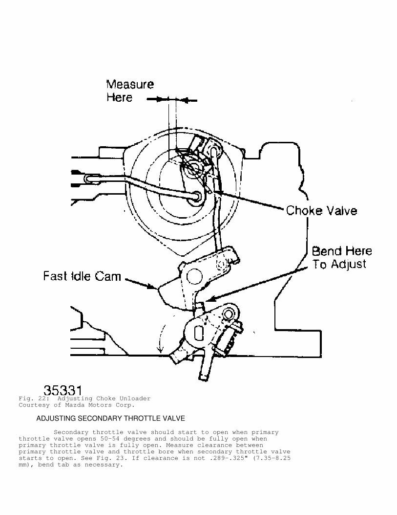
Fig. 22: Adjusting Choke UnloaderCourtesy of Mazda Motors Corp.
ADJUSTING SECONDARY THROTTLE VALVE
Secondary throttle valve should start to open when primarythrottle valve opens 50-54 degrees and should be fully open whenprimary throttle valve is fully open. Measure clearance betweenprimary throttle valve and throttle bore when secondary throttle valvestarts to open. See Fig. 23. If clearance is not .289-.325" (7.35-8.25mm), bend tab as necessary.
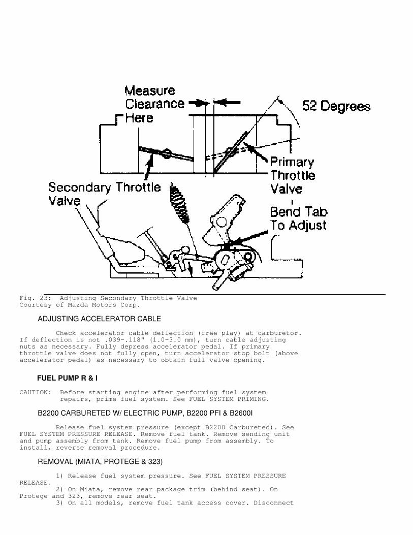
Fig. 23: Adjusting Secondary Throttle ValveCourtesy of Mazda Motors Corp.
ADJUSTING ACCELERATOR CABLE
Check accelerator cable deflection (free play) at carburetor.If deflection is not .039-.118" (1.0-3.0 mm), turn cable adjustingnuts as necessary. Fully depress accelerator pedal. If primarythrottle valve does not fully open, turn accelerator stop bolt (aboveaccelerator pedal) as necessary to obtain full valve opening.
FUEL PUMP R & I
CAUTION: Before starting engine after performing fuel system repairs, prime fuel system. See FUEL SYSTEM PRIMING.
B2200 CARBURETED W/ ELECTRIC PUMP, B2200 PFI & B2600I
Release fuel system pressure (except B2200 Carbureted). SeeFUEL SYSTEM PRESSURE RELEASE. Remove fuel tank. Remove sending unitand pump assembly from tank. Remove fuel pump from assembly. Toinstall, reverse removal procedure.
REMOVAL (MIATA, PROTEGE & 323)
1) Release fuel system pressure. See FUEL SYSTEM PRESSURERELEASE. 2) On Miata, remove rear package trim (behind seat). OnProtege and 323, remove rear seat. 3) On all models, remove fuel tank access cover. Disconnect
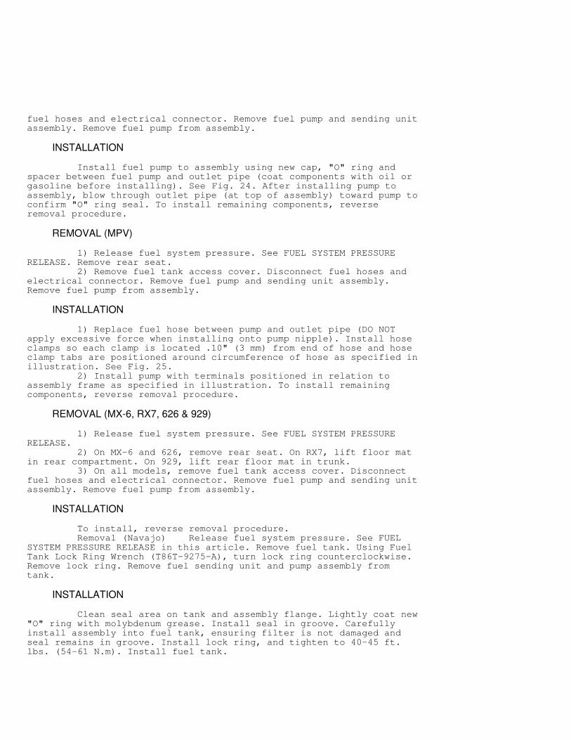
fuel hoses and electrical connector. Remove fuel pump and sending unitassembly. Remove fuel pump from assembly.
INSTALLATION
Install fuel pump to assembly using new cap, "O" ring andspacer between fuel pump and outlet pipe (coat components with oil orgasoline before installing). See Fig. 24. After installing pump toassembly, blow through outlet pipe (at top of assembly) toward pump toconfirm "O" ring seal. To install remaining components, reverseremoval procedure.
REMOVAL (MPV)
1) Release fuel system pressure. See FUEL SYSTEM PRESSURERELEASE. Remove rear seat. 2) Remove fuel tank access cover. Disconnect fuel hoses andelectrical connector. Remove fuel pump and sending unit assembly.Remove fuel pump from assembly.
INSTALLATION
1) Replace fuel hose between pump and outlet pipe (DO NOTapply excessive force when installing onto pump nipple). Install hoseclamps so each clamp is located .10" (3 mm) from end of hose and hoseclamp tabs are positioned around circumference of hose as specified inillustration. See Fig. 25. 2) Install pump with terminals positioned in relation toassembly frame as specified in illustration. To install remainingcomponents, reverse removal procedure.
REMOVAL (MX-6, RX7, 626 & 929)
1) Release fuel system pressure. See FUEL SYSTEM PRESSURERELEASE. 2) On MX-6 and 626, remove rear seat. On RX7, lift floor matin rear compartment. On 929, lift rear floor mat in trunk. 3) On all models, remove fuel tank access cover. Disconnectfuel hoses and electrical connector. Remove fuel pump and sending unitassembly. Remove fuel pump from assembly.
INSTALLATION
To install, reverse removal procedure. Removal (Navajo) Release fuel system pressure. See FUELSYSTEM PRESSURE RELEASE in this article. Remove fuel tank. Using FuelTank Lock Ring Wrench (T86T-9275-A), turn lock ring counterclockwise.Remove lock ring. Remove fuel sending unit and pump assembly fromtank.
INSTALLATION
Clean seal area on tank and assembly flange. Lightly coat new"O" ring with molybdenum grease. Install seal in groove. Carefullyinstall assembly into fuel tank, ensuring filter is not damaged andseal remains in groove. Install lock ring, and tighten to 40-45 ft.lbs. (54-61 N.m). Install fuel tank.
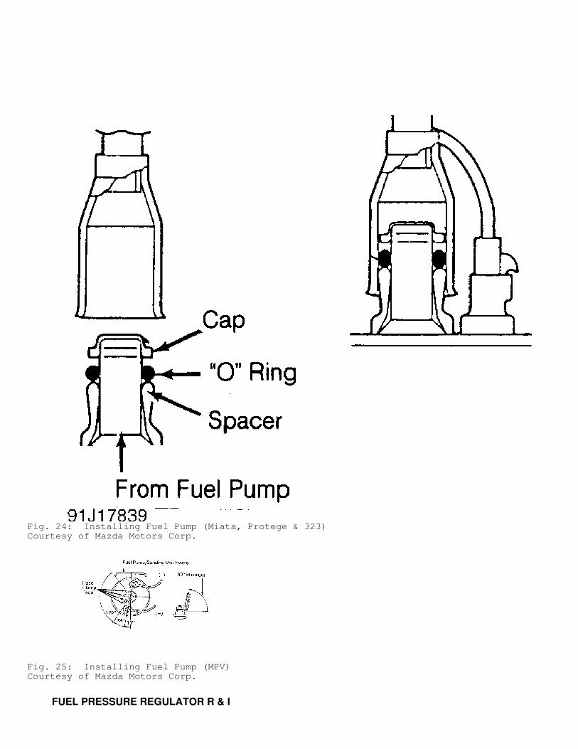
Fig. 24: Installing Fuel Pump (Miata, Protege & 323)Courtesy of Mazda Motors Corp.
Fig. 25: Installing Fuel Pump (MPV)Courtesy of Mazda Motors Corp.
FUEL PRESSURE REGULATOR R & I

CAUTION: Before starting engine after performing fuel system repairs, prime the fuel system. See FUEL SYSTEM PRIMING.
NAVAJO
1) Disconnect battery ground cable. Release fuel systempressure. See FUEL SYSTEM PRESSURE RELEASE. Disconnect vacuum hosefrom regulator. Disconnect fuel line coupling at regulator. See FUELLINE CONNECTORS (NAVAJO). 2) Remove regulator mounting bolts. Remove regulator, "O"ring and washer. To install, reverse removal procedure using newwasher and "O" ring. Lubricate new "O" ring with light oil. DO NOT usesilicone grease.
RX7
Fuel pressure regulator is part of secondary fuel rail. SeeFUEL RAILS & INJECTORS.
EXCEPT NAVAJO & RX7
1) Disconnect battery ground cable. Release fuel systempressure. See FUEL SYSTEM PRESSURE RELEASE. On MX-6 and 626, removedynamic chamber. On all models, disconnect vacuum and fuel hose(s)from regulator. Remove regulator mounting bolts. Remove regulator,gasket and "O" ring (if equipped). 2) To install, reverse removal procedure. Install new gasketand "O" ring (if equipped). On MX-6 and 626, install dynamic chamberwith new gasket, and tighten bolts to specification. See TORQUESPECIFICATIONS TABLE at end of article.
FUEL RAILS & INJECTORS R & I
CAUTION: Before starting engine after performing fuel system repairs, prime fuel system. See FUEL SYSTEM PRIMING.
B2200 PFI, B2600I & MPV 2.6L
1) Release fuel system pressure. See FUEL SYSTEM PRESSURERELEASE. Remove throttle body. See THROTTLE BODY. 2) Remove support brackets and injector harness bracket fromdynamic chamber. Disconnect vacuum hoses, PCV hose, intake airthermosensor connector and ground wire from dynamic chamber. Removedynamic chamber. 3) Disconnect vacuum hose and fuel hoses from fuel rail.Disconnect injector electrical connectors. Pull fuel rail withinjectors and pressure regulator upward to remove. Remove insulators,injectors and "O" rings from fuel rail. 4) To install, reverse removal procedure. Apply coat ofengine oil to new "O" rings and install on injectors. Install newinsulators. Tighten fuel rail mounting bolts to specification. SeeTORQUE SPECIFICATIONS TABLE at end of article. Install dynamic chamberwith new gasket.
MIATA
1) Release fuel system pressure. See FUEL SYSTEM PRESSURERELEASE. Disconnect negative battery cable. Remove air valve and PCVvalve from intake manifold. Disconnect vacuum and fuel hoses from fuelrail. Disconnect injector electrical connectors. Remove insulators,
injectors and "O" rings from fuel rail. 2) To install, reverse removal procedure. Apply coat ofengine oil to new "O" rings, and install rings on injectors. Installnew insulators. Tighten fuel rail mounting bolts to specification. SeeTORQUE SPECIFICATIONS TABLE at end of article.
MPV 3.0L & 929 SOHC
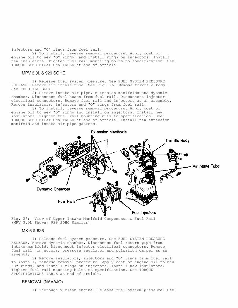
1) Release fuel system pressure. See FUEL SYSTEM PRESSURERELEASE. Remove air intake tube. See Fig. 26. Remove throttle body.See THROTTLE BODY. 2) Remove intake air pipe, extension manifolds and dynamicchamber. Disconnect fuel hoses from fuel rail. Disconnect injectorelectrical connectors. Remove fuel rail and injectors as an assembly.Remove insulators, injectors and "O" rings from fuel rail. 3) To install, reverse removal procedure. Apply coat ofengine oil to new "O" rings and install on injectors. Install newinsulators. Tighten fuel rail mounting nuts to specification. SeeTORQUE SPECIFICATIONS TABLE at end of article. Install new extensionmanifold and intake air pipe gaskets.
Fig. 26: View of Upper Intake Manifold Components & Fuel Rail(MPV 3.0L Shown; 929 SOHC Similar)
MX-6 & 626
1) Release fuel system pressure. See FUEL SYSTEM PRESSURERELEASE. Remove dynamic chamber. Disconnect fuel return pipe fromintake manifold. Disconnect injector electrical connectors. Removefuel rail, injectors, pressure regulator and pulsation damper as anassembly. 2) Remove insulators, injectors and "O" rings from fuel rail.To install, reverse removal procedure. Apply coat of engine oil to new"O" rings, and install rings on injectors. Install new insulators.Tighten fuel rail mounting bolts to specification. See TORQUESPECIFICATIONS TABLE at end of article.
REMOVAL (NAVAJO)
1) Thoroughly clean engine. Release fuel system pressure. See
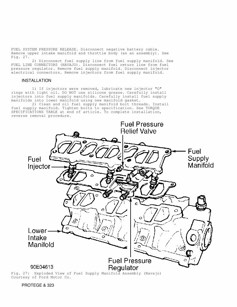
FUEL SYSTEM PRESSURE RELEASE. Disconnect negative battery cable.Remove upper intake manifold and throttle body (as an assembly). SeeFig. 27. 2) Disconnect fuel supply line from fuel supply manifold. SeeFUEL LINE CONNECTORS (NAVAJO). Disconnect fuel return line from fuelpressure regulator. Remove fuel supply manifold. Disconnect injectorelectrical connectors. Remove injectors from fuel supply manifold.
INSTALLATION
1) If injectors were removed, lubricate new injector "O"rings with light oil. DO NOT use silicone grease. Carefully installinjectors into fuel supply manifolds. Carefully install fuel supplymanifolds into lower manifold using new manifold gasket. 2) Clean and oil fuel supply manifold bolt threads. Installfuel supply manifold. Tighten bolts to specification. See TORQUESPECIFICATIONS TABLE at end of article. To complete installation,reverse removal procedure.
Fig. 27: Exploded View of Fuel Supply Manifold Assembly (Navajo)Courtesy of Ford Motor Co.
PROTEGE & 323
1) Release fuel system pressure. See FUEL SYSTEM PRESSURERELEASE. Disconnect injector electrical connectors. Remove injectorharness from fuel rail. Remove fuel rail mounting bolts. Remove fuelrail, injectors and pressure regulator as an assembly. 2) Remove insulators, injectors and "O" rings from fuel rail.To install, reverse removal procedure. Apply coat of engine oil to new"O" rings, and install rings on injectors. Install new insulators.Tighten fuel rail mounting bolts to specification. See TORQUESPECIFICATIONS TABLE at end of article.
REMOVAL (RX7)
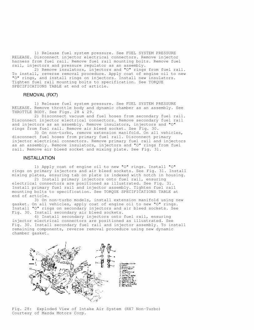
1) Release fuel system pressure. See FUEL SYSTEM PRESSURERELEASE. Remove throttle body and dynamic chamber as an assembly. SeeTHROTTLE BODY. See Figs. 28 & 29. 2) Disconnect vacuum and fuel hoses from secondary fuel rail.Disconnect injector electrical connectors. Remove secondary fuel railand injectors as an assembly. Remove insulators, injectors and "O"rings from fuel rail. Remove air bleed socket. See Fig. 30. 3) On non-turbo, remove extension manifold. On all vehicles,disconnect fuel hoses from primary fuel rail. Disconnect primaryinjector electrical connectors. Remove primary fuel rail and injectorsas an assembly. Remove insulators, injectors and "O" rings from fuelrail. Remove air bleed socket and mixing plate. See Fig. 31.
INSTALLATION
1) Apply coat of engine oil to new "O" rings. Install "O"rings on primary injectors and air bleed sockets. See Fig. 31. Installmixing plates, ensuring tab on plate is indexed with notch in housing. 2) Install primary injectors onto fuel rail, ensuringelectrical connectors are positioned as illustrated. See Fig. 31.Install primary fuel rail and injector assembly. Tighten fuel railmounting bolts to specification. See TORQUE SPECIFICATIONS TABLE atend of article. 3) On non-turbo models, install extension manifold using newgasket. On all vehicles, apply coat of engine oil to new "O" rings.Install "O" rings on secondary injectors and air bleed sockets. SeeFig. 30. Install secondary air bleed sockets. 4) Install secondary injectors onto fuel rail, ensuringinjector electrical connectors are positioned as illustrated. SeeFig. 30. Install secondary fuel rail and injector assembly. To installremaining components, reverse removal procedure using new dynamicchamber gasket.
Fig. 28: Exploded View of Intake Air System (RX7 Non-Turbo)Courtesy of Mazda Motors Corp.
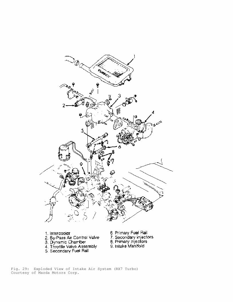
Fig. 29: Exploded View of Intake Air System (RX7 Turbo)Courtesy of Mazda Motors Corp.
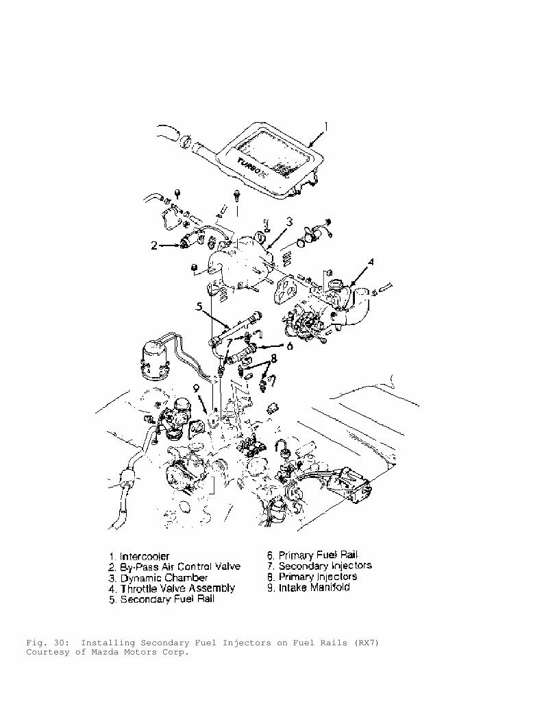
Fig. 30: Installing Secondary Fuel Injectors on Fuel Rails (RX7)Courtesy of Mazda Motors Corp.
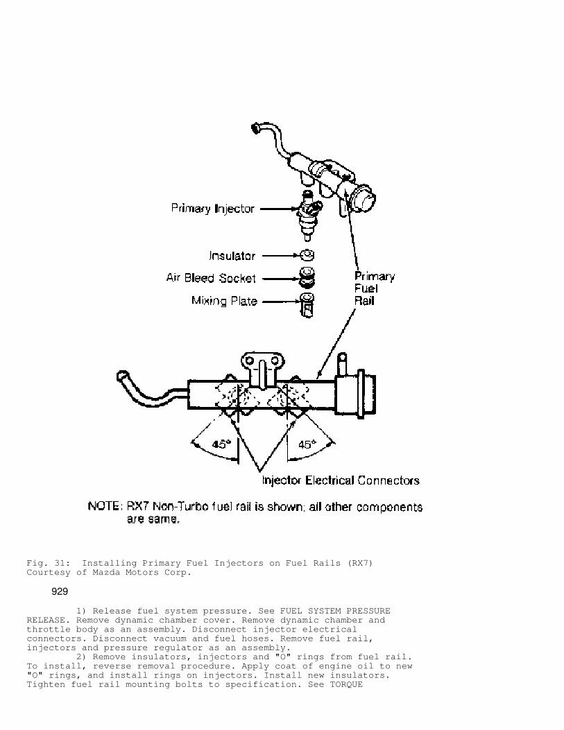
Fig. 31: Installing Primary Fuel Injectors on Fuel Rails (RX7)Courtesy of Mazda Motors Corp.
929
1) Release fuel system pressure. See FUEL SYSTEM PRESSURERELEASE. Remove dynamic chamber cover. Remove dynamic chamber andthrottle body as an assembly. Disconnect injector electricalconnectors. Disconnect vacuum and fuel hoses. Remove fuel rail,injectors and pressure regulator as an assembly. 2) Remove insulators, injectors and "O" rings from fuel rail.To install, reverse removal procedure. Apply coat of engine oil to new"O" rings, and install rings on injectors. Install new insulators.Tighten fuel rail mounting bolts to specification. See TORQUE
SPECIFICATIONS TABLE at end of article.
OXYGEN (O2) SENSOR R & I
REMOVAL
Disconnect oxygen sensor electrical connector. Sensor may bedifficult to remove when engine temperature is less than 120
�
F (48�
C).If sensor is difficult to remove, use rust penetrant to avoid damagingthreads. Carefully remove sensor.
INSTALLATION
Apply anti-seize to sensor threads (if reusing old sensor orif new sensor is not coated with anti-seize). Install sensor. SeeTORQUE SPECIFICATIONS TABLE at end of article. Reconnect sensorelectrical connector and negative battery cable.
THROTTLE BODY R & I
CAUTION: Before starting engine after performing fuel system repairs, prime the fuel system. See FUEL SYSTEM PRIMING.
RX7
1) Release fuel system pressure. See FUEL SYSTEM PRESSURERELEASE. Drain cooling system. On Turbo models, remove intercooler,oil filler pipe and Accelerated Warm-Up Solenoid (AWS) valve. SeeFig. 29. 2) On all models, remove throttle body air intake tube.Disconnect all necessary vacuum and coolant hoses, control cables andelectrical connectors from throttle body. 3) Remove throttle body and dynamic chamber as an assembly.Remove throttle body from dynamic chamber. To install, reverse removalprocedure using new gaskets. See TORQUE SPECIFICATIONS TABLE at end ofarticle.
EXCEPT RX7
1) On MPV 3.0L, drain about 2 qts. (1.9 L) of coolant fromcooling system. On all models, disconnect negative battery cable.Remove air intake tube. 2) Disconnect accelerator cable, coolant hoses and electricalconnectors from throttle body as necessary. On 929, remove by-pass aircontrol valve. On all models, remove throttle body. To install,reverse removal procedure using new throttle body gasket. See TORQUESPECIFICATIONS TABLE at end of article.
TURBOCHARGER
REMOVAL (MX-6 & 626)
1) Drain coolant. Remove air hoses and air by-pass valve.Remove heat shields. Disconnect oil hoses from oil pipes. See Fig. 32.Remove coolant hoses, EGR pipe and oxygen sensor. 2) Disconnect exhaust downpipe. Remove bolts securingturbocharger to bracket. Remove turbocharger and exhaust manifold asan assembly. Disassemble turbocharger and exhaust manifold.
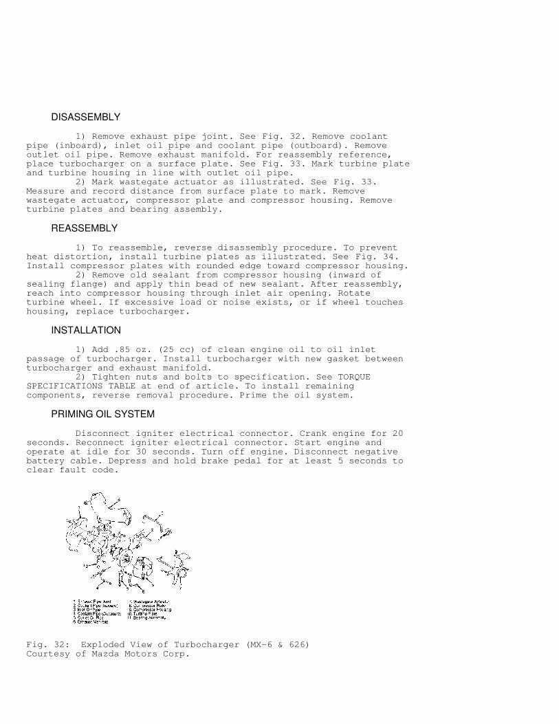
DISASSEMBLY
1) Remove exhaust pipe joint. See Fig. 32. Remove coolantpipe (inboard), inlet oil pipe and coolant pipe (outboard). Removeoutlet oil pipe. Remove exhaust manifold. For reassembly reference,place turbocharger on a surface plate. See Fig. 33. Mark turbine plateand turbine housing in line with outlet oil pipe. 2) Mark wastegate actuator as illustrated. See Fig. 33.Measure and record distance from surface plate to mark. Removewastegate actuator, compressor plate and compressor housing. Removeturbine plates and bearing assembly.
REASSEMBLY
1) To reassemble, reverse disassembly procedure. To preventheat distortion, install turbine plates as illustrated. See Fig. 34.Install compressor plates with rounded edge toward compressor housing. 2) Remove old sealant from compressor housing (inward ofsealing flange) and apply thin bead of new sealant. After reassembly,reach into compressor housing through inlet air opening. Rotateturbine wheel. If excessive load or noise exists, or if wheel toucheshousing, replace turbocharger.
INSTALLATION
1) Add .85 oz. (25 cc) of clean engine oil to oil inletpassage of turbocharger. Install turbocharger with new gasket betweenturbocharger and exhaust manifold. 2) Tighten nuts and bolts to specification. See TORQUESPECIFICATIONS TABLE at end of article. To install remainingcomponents, reverse removal procedure. Prime the oil system.
PRIMING OIL SYSTEM
Disconnect igniter electrical connector. Crank engine for 20seconds. Reconnect igniter electrical connector. Start engine andoperate at idle for 30 seconds. Turn off engine. Disconnect negativebattery cable. Depress and hold brake pedal for at least 5 seconds toclear fault code.
Fig. 32: Exploded View of Turbocharger (MX-6 & 626)Courtesy of Mazda Motors Corp.
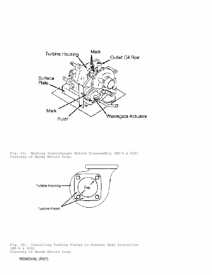
Fig. 33: Marking Turbocharger Before Disassembly (MX-6 & 626)Courtesy of Mazda Motors Corp.
Fig. 34: Installing Turbine Plates to Prevent Heat Distortion(MX-6 & 626)Courtesy of Mazda Motors Corp.
REMOVAL (RX7)
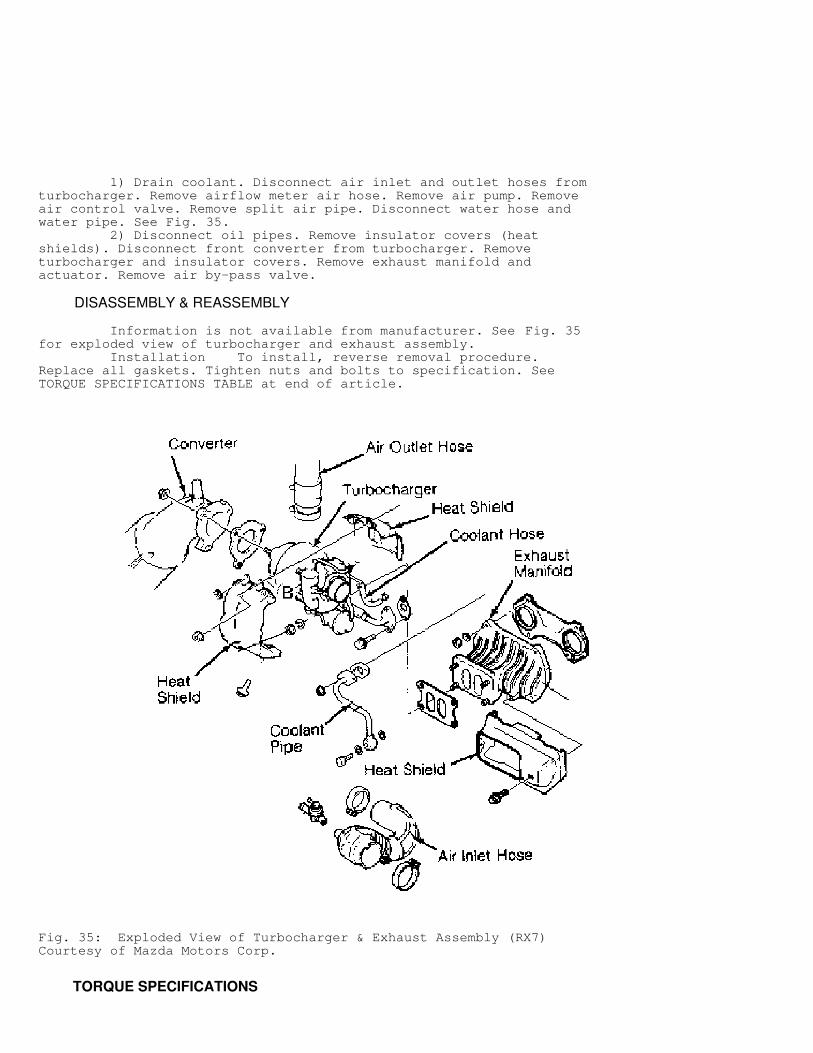
1) Drain coolant. Disconnect air inlet and outlet hoses fromturbocharger. Remove airflow meter air hose. Remove air pump. Removeair control valve. Remove split air pipe. Disconnect water hose andwater pipe. See Fig. 35. 2) Disconnect oil pipes. Remove insulator covers (heatshields). Disconnect front converter from turbocharger. Removeturbocharger and insulator covers. Remove exhaust manifold andactuator. Remove air by-pass valve.
DISASSEMBLY & REASSEMBLY
Information is not available from manufacturer. See Fig. 35for exploded view of turbocharger and exhaust assembly. Installation To install, reverse removal procedure.Replace all gaskets. Tighten nuts and bolts to specification. SeeTORQUE SPECIFICATIONS TABLE at end of article.
Fig. 35: Exploded View of Turbocharger & Exhaust Assembly (RX7)Courtesy of Mazda Motors Corp.
TORQUE SPECIFICATIONS
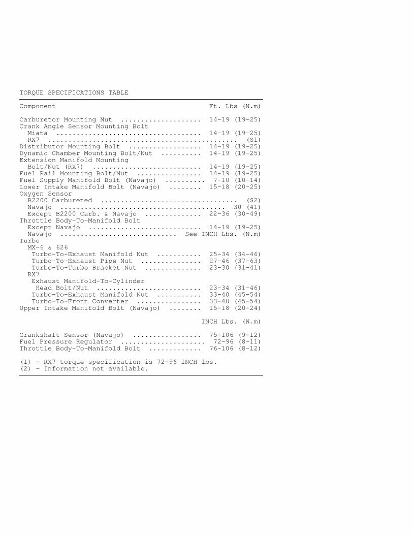
TORQUE SPECIFICATIONS TABLE�����������������������������������������������������������������������������������������������������������������������
Component Ft. Lbs (N.m)
Carburetor Mounting Nut .................... 14-19 (19-25)Crank Angle Sensor Mounting Bolt Miata .................................... 14-19 (19-25) RX7 ............................................... (S1)Distributor Mounting Bolt .................. 14-19 (19-25)Dynamic Chamber Mounting Bolt/Nut .......... 14-19 (19-25)Extension Manifold Mounting Bolt/Nut (RX7) ........................... 14-19 (19-25)Fuel Rail Mounting Bolt/Nut ................ 14-19 (19-25)Fuel Supply Manifold Bolt (Navajo) .......... 7-10 (10-14)Lower Intake Manifold Bolt (Navajo) ........ 15-18 (20-25)Oxygen Sensor B2200 Carbureted .................................. (S2) Navajo ......................................... 30 (41) Except B2200 Carb. & Navajo .............. 22-36 (30-49)Throttle Body-To-Manifold Bolt Except Navajo ............................ 14-19 (19-25) Navajo ............................. See INCH Lbs. (N.m)Turbo MX-6 & 626 Turbo-To-Exhaust Manifold Nut ........... 25-34 (34-46) Turbo-To-Exhaust Pipe Nut ............... 27-46 (37-63) Turbo-To-Turbo Bracket Nut .............. 23-30 (31-41) RX7 Exhaust Manifold-To-Cylinder Head Bolt/Nut .......................... 23-34 (31-46) Turbo-To-Exhaust Manifold Nut ........... 33-40 (45-54) Turbo-To-Front Converter ................ 33-40 (45-54)Upper Intake Manifold Bolt (Navajo) ........ 15-18 (20-24)
INCH Lbs. (N.m)
Crankshaft Sensor (Navajo) ................. 75-106 (9-12)Fuel Pressure Regulator ..................... 72-96 (8-11)Throttle Body-To-Manifold Bolt ............. 76-106 (8-12)
(1) - RX7 torque specification is 72-96 INCH lbs.(2) - Information not available.�����������������������������������������������������������������������������������������������������������������������