n94-29794 - nasa · 2013-08-30 · n94-29794 miniature wide field-of-view star trackers for...
TRANSCRIPT
N94- 29794
Miniature Wide Field-of-View Star Trackers
for Spacecraft Attitude Sensing & Navigation
William McCarty, Senior Staff Engineer
Eric Curtis, Vice President, Technical Director
Anthony Hull, Vice President, Engineering
William Morgan, Business Development Manager,
Space and Science Programs
OCA Applied Optics, Inc.
7421 Orangewood Avenue
Garden Grove, CA 92642
714/895-1667
Abstract:
Introducing a family of miniature, wide field-of-view Star Trackers for low cost, high
performance spacecraft attitude determination and navigation applications. These devices,
derivative of the WFOV Star Tracker Camera developed cooperatively by OCA Applied
Optics and the Lawrence Livermore National Laboratory for the Brilliant Pebbles program,
offer a suite of options addressing a wide range of spacecraft attitude measurement and
control requirements. These novel sensors employ much wider fields than are customary
(ranging between 20 and 60 degrees) to assure enough bright stars for quick and accurate
attitude determinations without long integration intervals. The key benefits of this approach
are light weight, low power, reduced data processing loads and high information carrier
rates for wide ACS bandwidths.
Devices described range from the proven OCA/LLNL WFOV Star Tracker Camera (a low-
cost, space-qualified star-field imager utilizing the spacecraft's own computer for
centroiding and position-finding), to a new autonomous subsystem design featuring dual-
redundant cameras and completely self-contained star-field data processing with output
quaternion solutions accurate to 100 ,arad, 3cy, for stand-alone applications.
317
https://ntrs.nasa.gov/search.jsp?R=19940025290 2020-07-13T16:45:10+00:00Z
Miniature Wide Field-of-View Star Trackers
for Spacecraft Attitude Sensing & Navigation
William McCarty, Senior Staff Engineer
Eric Curtis, Vice President, Technic:d Director
Anthony ltull, Vice President, Engineering
William Morgan, Business Development Manager,
Space and Science Programs
OCA Applied Optics, Inc.
7421 Orangewood Avenue
Garden Grove, CA 92642
714/895- 1667
1.0 LLNL/OCA STAR TRACKER CAMERA
The LLNL/OCA Star T,acker Camera was developed in support of the SDI Brilliant
Pebbles (BP) program by the I.awrence I.iverrnore National Laboratory and OCA. The BP
St_u Tracker Camera was designed to acquire star-field imagery from which spacecraft
attitude infomlation could be derived for navigation :rod to update and calibrate Inertial
Measurement Unit (IMU) attitude data. The WFOV Star Tracker Camera is unusual in that
it employs very wide field-of-view optics (nearly 60°), much greater than is customary for
Star Trackers. This wide-field design evolved from trade-studies early in the BP program
that showed this approach to be significantly more mass-efficient than traditional narrow
field designs. It's advantage results from the unique balance the design achieves between
FOV, aperture, focal plane sensitivity and the spatial distribution of bright stars in the sky.
Prototypes of this new class of sensor weighing just a few hundred grams routinely
achieve better than 200 microradian accuracy as reported recently by Lewis et al 1.
The generic WFOV Star Tracker Camera uses a 55 ° FOV concentric lens. The concentric
design-form maximizes relative aperture and eliminates lateral color effects that can
introduce stellar color temperature dependent centroid shifts. The focal surface in this
design is spherical, requiring the use of a fiber-optic faceplate (FOFP) with a spherically
curved front surface to flatten the field for interface to the CCD imaging device. This
design approach delivers a fast optical system in a very compact, low mass package with a
318
2
relative aperture almost twice as large as flat-field design-fomls of comparable
performance.
Both intensified and unintensified versions of the WFOV Stm" Tracker Camera have been
prototyped and tested. The intensified variants employ a gated, second-generation,
proximity-focused image intensifier between the lens and the CCD to increase sensitivity
enough to allow a corresponding decrease in integration time. This configuration assures
full performance on vehicles with relatively high attitude drift rates by using its short
integration time (typically, 30 to 50 msec) to avoid degradation from image smear.
Unintensified versions are much lighter (weighing less than 130 grams) and achieve full
performance on platforms with drift rates up to about l°/hour (where integration periods as
long as 400 msec are practical). With current commercial focal plane readout noise levels
as low as 40 to 60 electrons, unintensified cameras perform well with integration periods of
about 100 msec. Advanced technology focal planes reduce that period considerably. In the
presence of limiting background flux (where the net signal-to-noise ratio becomes
background limited), the unintensified array will actually allow shorter integration times
than an intensified camera because of its superior quantum efficiency and broader spectral
bandwidth.
The basic Wide Field-of-view Star Tracker concept has several important advantages over
traditional approaches. Key among them is that the probability of finding bright stars
increases with the solid angle surveyed (FOV). Therefore, as field-of view increases, so
too will the number of bright stars included within it. Further, since there are relatively few
bright stars in the sky (less than 500 brighter than M,, = 4), a large FOV assures that only a
small catalog of the very brightest need be considered for navigation. With such a small
star map to manage, it is quite practical to use fast pattern-matching techniques to reliably
detem-fine the orientation of a spacecraft in near real-time.
With the focal plane stray light flux distributions anticipated in typical service, WFOV Star
Tracker imagery ordinarily requires processing to subtract the average local background
signal from each pixel. This is automatic where the signal amplitude distribution of a
cluster of pixels is found to match the nominal blur energy distribution of an imaged point
source (probable star). Star Tracker maximum stray light limits are imposed by either
saturation effects (where the sum of signal and background fluxes exceed CCD well
capacity or the dynamic range of subsequent signal electronics) or by the shot noise of the
background. In the case of dim stars, shot noise limits the maximum background flux
before saturation becomes a problem. Stray light analyses using the APART code indicate
319
maximum point source transmittance (PST) for a typical baffle is about lxl0 -7 for all sun
angles beyond the solar exclusion angle. For sun positions just approaching the solar
exclusion angle, the exact rnagnitude of the stray light becomes a major factor in
determining minimum integration times lb, both the intensified and unintensified sensors.
Inside the solar exclusion angle, one or more optical sutTaces will be directly illuminated by
the sun and the stray light signal increases dramatically, overwhelming the dimmer stars.
The image processing algorithm identifies stars by evaluating the amplitude characteristics
of candidate pixel clusters. The key discrimination criteria require that, 1), the peak pixel
anaplitude(s) remain below saturation (normally the case, except for the very brightest stars)
and 2) that the character of the intensity profile o1' the pixel cluster match the expected point-
spread function (PSF) of a nomlal image. Thus, a single, isolated pixel will not be
identified as a star, even though: it exhibits approl_riate signal amplitude,_ because the
amplitude of its neighboring pixels won't conlkmn to the expected PSF intensity contour.=
It is important to note that the sub-pixel centroiding accuracy of the Star Tracker's image
processing algorithms, nominally about t/10 pixcl, would not be possible if the star's blur
diameter were not larger than a single pixel. The unique concentric optic of the WFOV Star
Tracker Camera not only provides the proper image scale for optinaum centroiding, but
maintains essentially perfect scale unifornait,,, across its full working format.
Once all of the potential star images within a data field have been located, the brightest are
grouped into candidate star-triangles, iteratively compared against star catalog data and
ultimately resolved into confirmed star-triangle matches. The algorithm typically uses a
minimum of five star-triangle matches (requiring at least five detectable stars per data field)
in order to establish the attitude of the sensor within prescribed error limits. The orientation
of the Star Tracker's optical axis (and thus the spacecraft's attitude) is ultimately expressed
as an output quaternian developed from the individual rotation quaternians for each of the
star triangle matches in the ensemble (and in which any residual star position errors have
been evenly distributed).- =
WFOV Star Trackers can reliably establish their orientation with only a relatively simple
corrective term to standardize the position-finding algorithm for hardware variances. Just
three quantities are needed for this correction; 1) the as-mant, factured effective focal length,
2) static boresight position error and 3) the two-dimensional distortion characteristics of the
basic optical design (each quantity _ing referenced to the Origin of the focal plane
coordinate system and expressed to an accuracy <3 btm), No special measurement or
320

specific correlation of actual (individually measured) PSF variations across the field-of-
view is needed to achieve nominal angular precision.
1.1 WFOV Star Tracker Optics Assy
The generic WFOV Star Tracker optic is a 3 element f/1.26 design yielding a 55 degree
diagonal working field. The central, spherical (ball) element is of Schott SSK4 glass and
the front and rear concentric shell elements are Ohara SLF02 and Schott LaF20,
respectively. A fiber-optic faceplate provides the curved image surface to interface the
spherical image front of the lens to the planar CCD array.
1.2 WFOV Star Tracker Focal Plane Electronics
The baseline focal plane detector device for the WFOV Star Tracker Camera is a Thomson-
CSF TH7883 CCD array. The TH7883 is derived from the TH7863 array by transforming
its storage zone into an imaging area, identical and adjacent to the original imaging zone,
thereby doubling its active imaging area. The array is read out as a single field of 576
active lines with 384 active pixels per line. Pixels measure 23 bun by 23 lain, yielding an
active imaging area of 8.832 mm by 13.248 ram. The pixel instantaneous field-of-view
(IFOV) is 1.3 milliradians, square. The array, with its surface-mount readout electronics,
is packaged into a compact space-qualified focal plane assembly on a multi-layer flex-print
circuit board. Power, control and digital video interfaces are implemented through a single
miniature 50-pin connector.
2.0 OCA ADVANCED STAR TRACKER ASSEMBLY
OCA's Advanced Star Tracker Assembly (ASTA) is a new, completely self-contained,
light-weight, high-performance star tracker system for space applications. The ASTA
design has evolved from its WFOV Star Tracker origins in response to needs for a fully
integrated star tracker system able to meet the demanding mass, power and performance
goals of next-generation light-weight spacecraft. This new design capitalizes on the unique
attributes of the LLNL/OCA Wide Field-of-view Star Tracker Camera, developed originally
for the SDI Brilliant Pebbles program, and extends that heritage to realize a wholly self-
contained attitude measurement system weighing less than 1.2 kg and nominally accurate to
+ 100 microradians, 3_.
321
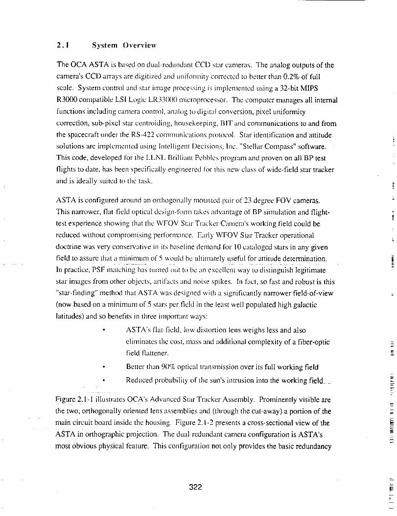
2.1 System Overview
The OCA ASTA is based on dual-redundant CCD star cameras. The analog outputs of the
camera's CCD arrays are digitized and unifornfity COJTected to better than 0.2% of full
scale. System control and star image processing is implemented using a 32-bit MIPS
R3000 compatible LSI Logic LR33000 microprocessor. The computer manages all internal
functions including camera control, analog to digital conversion, pixel uniformity
correction, sub-pixel stzu centroiding, housekeeping, BIT and communications to and from
the spacecraft under the RS-422 communications protocol. Star identification and attitude
solutions are implemented using Intelligent Decisions, Inc. "Stellar Compass" software.
This code, developed for the LLNL Brilliant Pebbles program and proven on all BP test
flights to date, has been specifically engineered tbr this new class of wide-field star tracker
and is ideally suited to the task.
ASTA is configured around an orthogonally mounted pair of 23 degree FOV cameras.
This narrower, flat-fie!d 0Ptical des!gn-f_!-n? take s advantage Of BP s!mulati0n and flight-
test experience showing that the WFOV Star Tracker Camera's working field could be
reduced without compromising performance. Early WFOV Star Tracker operational
doctrine was very conservative in its baseline demand for 10 cataloged stars in any given
field to assure that a minimum of 5 would be ultimately useful for attitude determination.
In practice, PSF matching has turned out to be an excellent way to distinguish legitimate
star images frorn other objects, artifacts and noise spikes. In fact, so fast and robust is this
"star-finding" method that ASTA was designed with a significantly narrower field-of-view
(now based on a minimum of 5 stars per field in the least well populated high galactic
latitudes) and so benefits in three important ways:
ASTA's flat-field, low distortion lens weighs less and also
eliminates tt_e cost, mass and additional complexity of a fiber-optic
field flattener.
• Better than 90% optical transmission over its full working field
• Reduced probability of the surfs intrusion into the working field
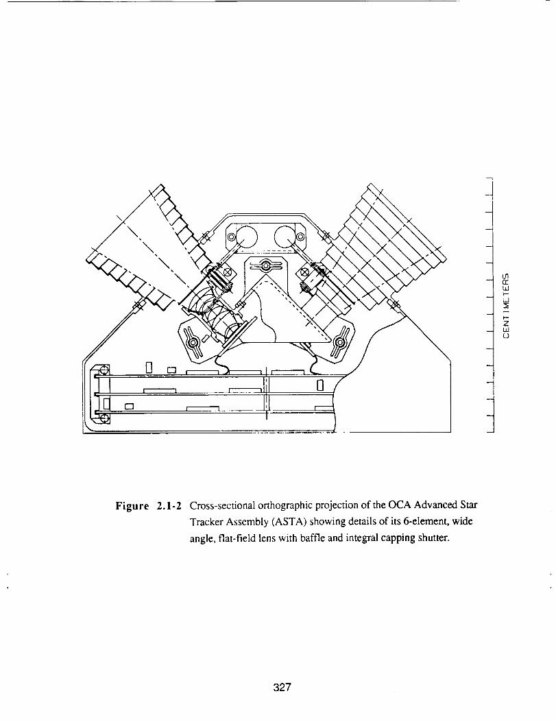
Figure 2.1-1 illustrates OCA's Advanced Star Tracker Assembly. Prominently visible are
the two, orthogonally oriented lens assemblies and (through the cut-away) a portion of the
main circuit board inside the housing. Figure 2.i'2 presents a cross-sectional view of the
ASTA in orthographic projection. The dual-redundant camera configuration is ASTA's
most obvious physical feature. This configuration not only provides the basic redundancy
322
of two separate and complete cameras (independent optics, focal plane and analog video
circuitry) but, more importantly, assures reliable high-accuracy attitude data irrespective of
the spacecraft's orientation or rotational axis. If the sun should happen to intrude into one
camera's field, attitude measurements may be conveniently made using the other camera
rather than by re-orienting the spacecraft. Even nlore importantly, the dual-camera design
avoids the potential for large errors resulting when the spacecraft's instantaneous axis of
rotation lies near the optical axis of one of the cameras. This problem arises from the
sharply increasing influence of residual star centroid errors on the output quatemian's roll
component as the spacecraft's roll axis approaches the sensor's line-of-sight. In practice,
ASTA's control software features can select the proper camera based on IMU attitude data
from the spacecraft or will autonlatically switch to the alternate field if the roll axis is found
to lie too close to the current sensor's optical axis.
The ASTA optics use the sanle 14 111111entrance pupil diameter (aperture) typical of the
WFOV Camera but take advantage of improved net optical transmission (gained by
eliminating the WFOV Star Camera's FOFP field flattener) and new low noise read-out
electronics to extend its working range down to stars of M,, = 5.1 with normal integration
periods of only 20 msec. This configuration still allows a conveniently small star catalog
(1024 stars) to assure attitude updates at 33 nlsec intervals with completely deterministic
data latency characteristics.
As an illustration of its robustness it is significant to note that ASTA is designed to deliver
its specified performance under worst-case conditions but, in actual practice the statistical
distribution of stars is such that it is only necessary to use stars fainter the My = 4.5 about
4% of the time and, normally, fully half of the stars will be brighter than My = 3.6.
ASTA optics are baffled externally by a single-stage multi-vane sun-shade with integral
capping shutter. The shutter protects against the long-tema build-up of scattering
contaminants (and atomic oxygen erosion in LEO) and, when closed, provides an active
diffuse radiometric calibration stimulus for in situ CCD gain normalization.
Stray light analyses reliably predict a sun equivalent PSNIT = 1 x 10 .8 for these optics with
the Sun at its closest working (exclusion) angle of 30 degrees. This allows sufficient
margin to assure specified performance even with a realistic allowance for degradation due
to space contamination build-up over time.
The 6 element, thin section optical design is based on generally available Schott radiation-
tolerant (anti-browning) glasses.
323

2.2 Summary Specificalions
Optics Equivalent Focal Length:
Entrance Pupil Dimnete,':
D._'al ratio:
PSF Energy Distribution:
Ensquared Energy:
Field of View (FOV):
22 mrn
14 mm
./'/1.57
-70c/_ central pixel, -30 % adjacent eight pixels
> 6()q everywhere within working field
23 ° , circular
Instantaneot[s Field of View (IFOV:)I:" 21 :inrad ' :
Spectral Range: 500- 1000 nm (full spectrum)
Transmission: > 90% within working field (full spectrum)
hnage Format: 8.84 ram, square
CCD Imaging Device:
Quanturn Efficiency:
Pixcl dimensions:
Pixei arrangement:
Array dimensions:
Readout Noise:
Integration Time:
Frame Rate:
Thomson-CSF TH7883 CCD
> 35%
23 btm, square
384 (V) x 384 (H) (usable pixels)
8.83 mm (V) x 8.83 mm (H) (usable area)
< 40 e-, 1_, rms
va,iable, 20 msec nominal
30 fps (lllax, full field)
Image Processing Data Latency:
Stellar Compass Processing Time:
Attitude Accuracy:
Video Quantization:
Offset Unil\mnity:
Gain Uniformity:
Integration time dependent, fully detemfinistic
2 msec (quaternian computation)
+I(X) btradians, 3_, for drift rates <10°/min
9 bits effective (dim stars)
Corrected to 0.2% full scale
Corrected to 0.2% full scale
Power
Mass
Operating Voltages:
Nomiiiai Operating Power:
Shutier Actuation Power:
Stand-by (idle) Mode:
Optical Subassembly:
Electronics Subassembly:
Mechanical Subassembly:
STA, Total Mass:
+5.0, +15.0, 28.0 +6 VDC
6.5 W (worst case peak)
2.2 W peak, 0.5 W holding0.7 W
89 g
640 g
317g
1,046 g
lI.Lewis, A.Ledebuher, T.Axclrod, J.Kordas and R.Hills, "WFOV Sutr Tracker Camera, UCRL-JC-105345,
proc. SPiE international Symposium on Optical Engineering & Photonics in Aerospace Sensing, Orlando,
FL, April 1-5, 1991.
324
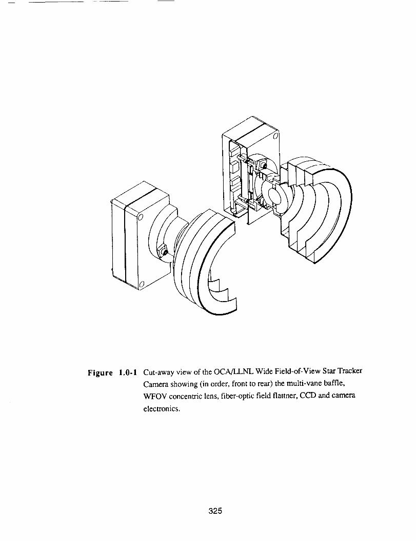
Figure 1.0-1 Cut-away view of the OCA/LLNL Wide Field-of-View Star Tracker
Camera showing (in order, front to rear) the multi-vane baffle,
WFOV concentric lens, fiber-optic field flatmer, CCD and camera
electronics.
325
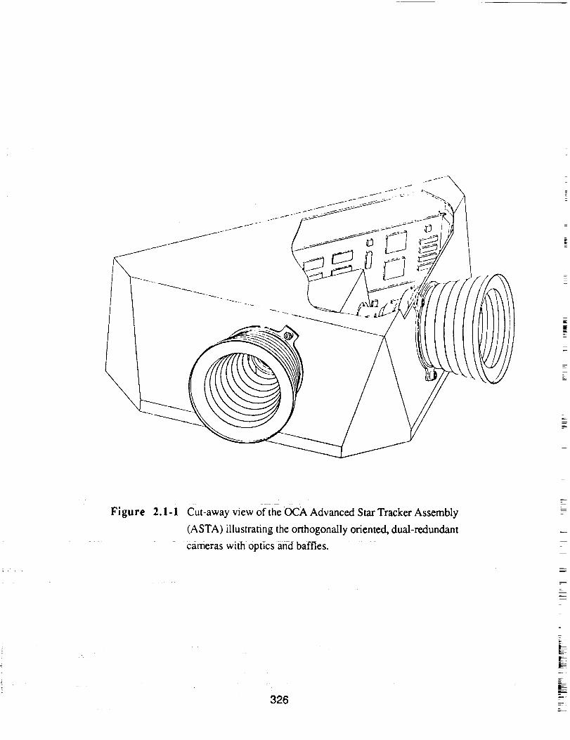
Figure 2.1- I cut-away view of the OCA Advanced Star Tracker Assembly
(ASTA) illustrating the orthogonally oriented, dual-redundant
cameras with optics and baffles.
326
\
\ ,\
\\
0 n
n
0
w
l
m
oqIzt.dk--
W
Zwo
Figure 2.1-2 Cross-sectional orthographic projection of the OCA Advanced Star
Tracker Assembly (ASTA) showing details of its 6-element, wide
angle, flat-field lens with baffle and integral capping shutter.
327

NOVEL POSITION SENSOR TECHNOLOGIESFOR
MICRO ACCELFROMETERS*
T. R. Van Zandt, T. W. Kenny, and W. J. KaiserCenter for Space Microelectronics Technology
Jet Propulsion Laboratory, California Institute of TechnologyPasadena, California 91109
ABSTRACT
An important new approach for vehicle guidance and control isbased on the use of compact, low-mass, low-cost sensors integratedwith the vehicle structure. Many advantages of this approach lead tonew capabilities. However, the development of compact guidanceand control sensors leads to a variety of fundamental physicalproblems associated with sensor sensitivity and noise. For example,as sensor size is reduced, it becomes necessary to improve thesensitivity of the sensor signal detection mechanism. For anaccelerometer, the position sensor must be more sensitive if theaccelerometer proof mass is to be reduced. In addition, asaccelerometer proof mass is reduced, thermal noise appears in themotion of the proof mass, thus degrading the resolution of theaccelerometer. These challenges to sensor development will bedescribed.
Recent developments at JPL, based on new position sensorprinciples such as electron tunneling, have produced a series ofnovel, ultra-high sensitivity microsensors and microinstruments.Included among the applications demonstrated are a high-sensitivitymicro-seismometer and micro-accelerometer. In this presentation,
the principles and performance of these devices will be described. Itwill be shown that the implementation of micro instruments usingthese principles produces systems having performance equivalent toprevious conventional instruments, but, with major reductions inmass, volume, and power consumption.
* Research supported by NASA, DARPA, and SDIO/IST.
P_N_ P_',_E BLAt_K NOT Fti..h_El,_-
329


Microtechnologies
and
Applications to Space Systems Workshop
SUMMARY REPORTS
I_I_C,,II_N6 OI_'3E BLANK I_)T FI_M_r.- 331

REPORT OF THE MICROSPACECRAFT PANEL
Chairmen
Ross M. Jones
Jet Propulsion Laboratory, California Institute of Technology
Denis ConnollyNASA Lewis Research Center
This report is based in part on material presented at the
workshop on
MICROTECHNOLOGIES AND APPLICATIONS TO SPACE SYSTEMS
Jet Propulsion Laboratory
California Institute of TechnologyMay 27 & 28, 1992
Sponsored by:
National Aeronautics and Space Administration
Office of Aeronautics and Space Technology
PAGE BLANK NOT FILMED 333
REPORT OF THE MICROSPACECRAFT PANEL
INTRODUCTION
These findings and recommendations are based solely on the
material presented during the Microtechnologies and Applications
to Space Systems Workshop, 5/27 & 28/92, and the personal
knowledge and judgment of the panel members. These findings and
recommendations represent the consensus views of the committee.
The mission utility of microspacecraft for NASA space science
missions was not an issue that the panel addressed. For the
purposes of this panel, a microspacecraft was defined to be a
fully functional spacecraft, intended for use on NASA spacescience missions, whose mass is on the order of i0 kg. During the
panel discussions the microspacecraft mass definition was usedsomewhat loosely to be not less than i0 kg but certainly not more
than i00, dependent upon the mission requirements.
PANEL SCOPE
The scope of the panel is presented here in order to put the
panel report into context.
"The panel report will attempt to identify areas that
need additional development to enable a microspacecraft
for NASA space science missions. These areas will span
technology development through space qualification of
the microspacecraft system. The panel will deal with
two top level issues: I) integrating advances in
technology into the microspacecraft system and 2)
identifying present limits of obstacles to achieving a
microspacecraft. These limits or obstacles will be
further defined as either fundamental or only based
upon the present state of technology, and therefore afertile area for improvement with increased resources.
The panel will be concerned with all spacecraft
subsystems, i.e., instruments, power, propulsion,
attitude control, command & data, telecommunications,
thermal and structure/cabling/mechanisms."
The scope of the panel evolved somewhat from the above during the
discussions on 5/29. Contrary to the what is written above, the
panel did not concern itself specifically with (science)
instruments.
334
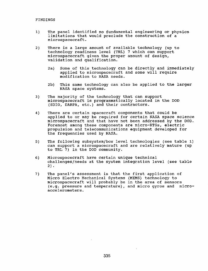
FINDINGS
I)
2)
3)
4)
5)
6)
7)
The panel identified no fundamental engineering or physics
limitations that would preclude the construction of a
microspacecraft.
There is a large amount of available technology (up to
technology readiness level (TRL) 7 which can support
microspacecraft given the proper amount of design,
validation and qualification.
2a) Some of this technology can be directly and immediately
applied to microspacecraft and some will requiremodification to NASA needs.
2b) This same technology can also be applied to the larger
NASA space systems.
The majority of the technology that can support
microspacecraft is programmatically located in the DOD
(SDIO, DARPA, etc.) and their contractors.
There are certain spacecraft components that could be
applied to or may be required for certain NASA space science
microspacecraft and that have not been addressed by the DOD.
Foremost among these components are micro-RTGs, electric
propulsion and telecommunications equipment developed for
the frequencies used by NASA.
The following subsystem/box level technologies (see table I)
can support a microspacecraft and are relatively mature (up
to TRL 7) in the DOD community.
Microspacecraft have certain unique technical
challenges/needs at the system integration level (see table
2).
The panel's assessment is that the first application of
Micro Electro Mechanical Systems (MEMS) technology to
microspacecraft will probably be in the area of sensors
(e.g. pressure and temperature), and micro gyros and micro-accelerometers.
335

Table 1
Technologies Resident at DOD Contractors
that Could Support a NASA Microspacecraft
Structures/Mechanisms
shaped memory actuators - d
composite sandwich panel & trusses (metal & polymer matrix
composites) - d
high thermal conductivity composites & phase change material - d
Power
high efficiency solar cells - d
high energy density battery cells - m
Command and Data
data compression - d/m
opto electronics - m
high capacity bulk data storage parts - d
Telecommunications
active arrays - m
digital receivers - m
Ka band and higher frequencies -m
optical communications - m
Attitude Control
fiber optic and ring laser gyros - d
miniature star cameras/trackers - d
lightweight reaction/momentum wheels - d
ProDulsion
mono and bi-prop engines - m
high pressure fiber overwrapped propellant & pressurant tanks - d
lightweight valves and regulators - m/d
Electronic Packaqinq
surface mount technology - d
multichip modules - d
3-D packaging - d
wafer scale integration - m
MMIC - d
d = can be directly applied to NASA microspacecraft (may require
re-qualification for a NASA mission)
m = requires modification and qualification for NASA needs
336
i)
2)
3)
4)
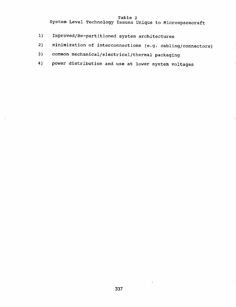
Table 2
System Level Technology Issues Unique to Microspacecraft
Improved/Re-partitioned system architectures
minimization of interconnections (e.g. cabling/connectors)
common mechanical/electrical/thermal packaging
power distribution and use at lower system voltages
337

RECOMMENDATIONS TO NASA
(ranked according to priority)
i) Establish a program to flight demonstrate microspacecraft.
la) Vigorously pursue the transfer, qualification andinsertion of DOD developed technologies (defined in
finding #5) to NASA missions, systems and subsystems.
ib) In cooperation with NASA codes SL, SS, SZ, SE and QE,
support system/mission studies of the microspacecraft
concept with the goal of more effectively presenting
the applications, requirements and pros and cons of
microspacecraft.
ic) Support the development of microspacecraft technologieswhich are either unique to microspacecraft or which
have not been supported by the DOD (defined in findings
# 4 & 6).
2)
3)
Support the MEMS community with a small (-$0.5) program and
encourage investigations into NASA applications.
Convene a microspacecraft working group to increase
communication between users and technologists. This working
group should consist of representatives from NASA usercenters, NASA technology centers, codes R, S and Q and the
DOD contractor community.
338

_-Zzo01-.O_a_z z_ww_O_zO_0
Oz
,.J
-1
rl©
111I--if)
339

g
oz_
LI©
.Ji]."1
iiiI-(/)>-(/)m
(/)
<{(/)I---
zZO0m
EZO<!,11. uP-(j_Zz>.<
wO
g N_,.,0. ..lZ
_g P-
o_ _'>
< =_ _'
a0 zwLUl. _
:3 N< W_r3 _ ous
:31--0 po _z_-r
i
340
341
nnn0
342
343

344
II©
_L
>-m
o,=oUJ
OLUf.-
,.I
"1
UJ!--(/)>-(/)
I--ZiiiZOQ.=EOO
I
UJ>UJ..i
(/)iiiZ
UJE!--ZLUEE
o
l-D:
I-(/)
OZm
Z
ii
OEu.(/)E
uJ>-
Om
p.
n-!-(/)XO=EUJ
E_
_J
_'LUU-I--(/) (/)n'>-_mLUEI
Om
I-
El--COZO=EUJ
"1"
,JILl_
345
0
0
(5
0111
0
(.0
=.Iel-1
346
©
ooO
o,,=,0
347

U
=
_ k
,=
WORKSHOP PROCEEDINGS:
MICROTECHNOLOGIES AND APPLICATIONS TO SPACE SYSTEMS
Workshop Summary Report
Study Coordinator and Proceedings Editor: B.A. WilsonJet Propulsion Laboratory, California Institute of Technology
Workshop Chairs: F.Y. Hadaegh, W.J. Kaiser and B.A. WilsonJet Propulsion Laboratory, California Institute of Technology
Microtechnologies offer the potential of enabling or enhancing NASA missions in a variety ofways. Following in the footsteps of the microelectronics revolution, the emerging micro-electro-mechanical systems (MEMS) technology, which offers the integration of recent advances inmicromachining and nanofabrication techniques with microelectronics in a mass-producible format,is viewed as the next step in device and instrument miniaturization. In the course of identifying themajor areas of impact for future space missions, the following three categories emerged:
• Miniaturization of components and systems, where the primary benefit is areduction in size, mass and/or power. (Example: Microspacecraft.)
New capabilities and enhanced performance, where the most significantimpact is in performance, regardless of system size. (Example: Opticaldomain image processing.)
Distributed (multi-node) systems and missions, a new system paradigm inwhich the functionality is enabled through a multiplicity of elements.(Examples: Distributed networks of sensors for mapping, constellations ofmicrospacecraft, or distributed health management sensor systems.)
The first category is the most obvious, and, not surprisingly, encompasses many of the importantapplications identified in this report. Nevertheless, there are also numerous examples of significantimpact in the other two categories, and because they are more likely to be overlooked in a cursorysurvey, represent some of the most significant contributions of this study.
MINIATURIZATION OF COMPONENTS AND SYSTEMS
It is generally recognized that future large flagship missions will be fewer and farther between,and that we have entered an era in which smaller, lower budget missions will dominate NASA'sspace exploration suite. Consequently, there is a critical focus on making everything smaller,lower mass and lower power, preferably with little or no sacrifice in capability or performance.The near-term targets are for Pegasus-launched microspacecraft, for which the total massallocation, all subsystems and instruments combined, is 10 - 400 kg. Instruments formicrospacecraft missions must be concomitantly small, typically under 1 kg. The feasibility ofsmall (< 20 kg) and miniature (< 2 kg) planetary rovers is also being considered.
The Microspacecraft panel reviewed requirements for and obstacles to achieving a 10 - 400kg, first-generation microspacecraft, and no fundamental engineering or physics limitations were
identified. Much of the required technology has already been developed, primarily within the DoDcommunity. Key technology developments yet required include micro radioisotope thermoelectricpower generators, electric propulsion, Ka-band communication systems, and embedded physical
PAGE BLANK NOT FI,L_ED 34g
sensors.Spaceand masslimitations ona microspacecraftmayprecludeconventionalmodularapproaches,calling for additionalsystemsinteg.rationissuesto beaddressed.Othertechnologiessuchashigh-densitybatteries,datacompressiontechniques,mono-, bi- and solid propellantenginesand various mechanical,optoelectronicand communicationsystems,require furthermodificationto meetspecificNASA requirements.
A numberof overall recommendationswere generatedconcerningthe developmentandimplementationof afirst-generationmicrospacecraft.Rankedin orderof priority, theseare:
• Establishaprogramto flight demonstratemicrospacecraft.- Vigorouslypursuethetransfer,qualificationandinsertionof DoD-developedtechnologiesto
NASA missions,systemsandsubsystems.- In cooperationwith NASA CodesSL, SS,SZ, SEandQE,supportsystem/missionstudies
of the microspacecraftconceptwith the goal of moreeffectively presentingapplications,requirements,andprosandconsof microspacecraft.Supportthedevelopmentof microspacecrafttechnologiesthatareeitheruniqueto NASA orhavenotbeenadequatelysupportedby DoD.
• Supportthe micro-electro-mechanicalsystemsR&D community with small programsandencourageinvestigationintoNASA applications.
• Convenea MicrospacecraftWorking Group to increasecommunicationbetweenusersandtechnologists.This workinggroupshouldconsistof representativesfrom NASA usercenters,NASA technologycenters,CodesR, S andQ, andtheDoD contractorcommunity.
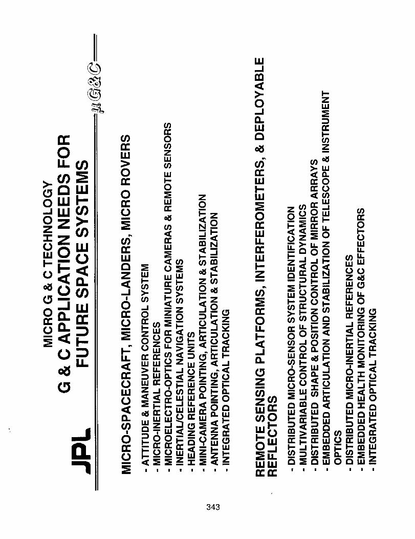
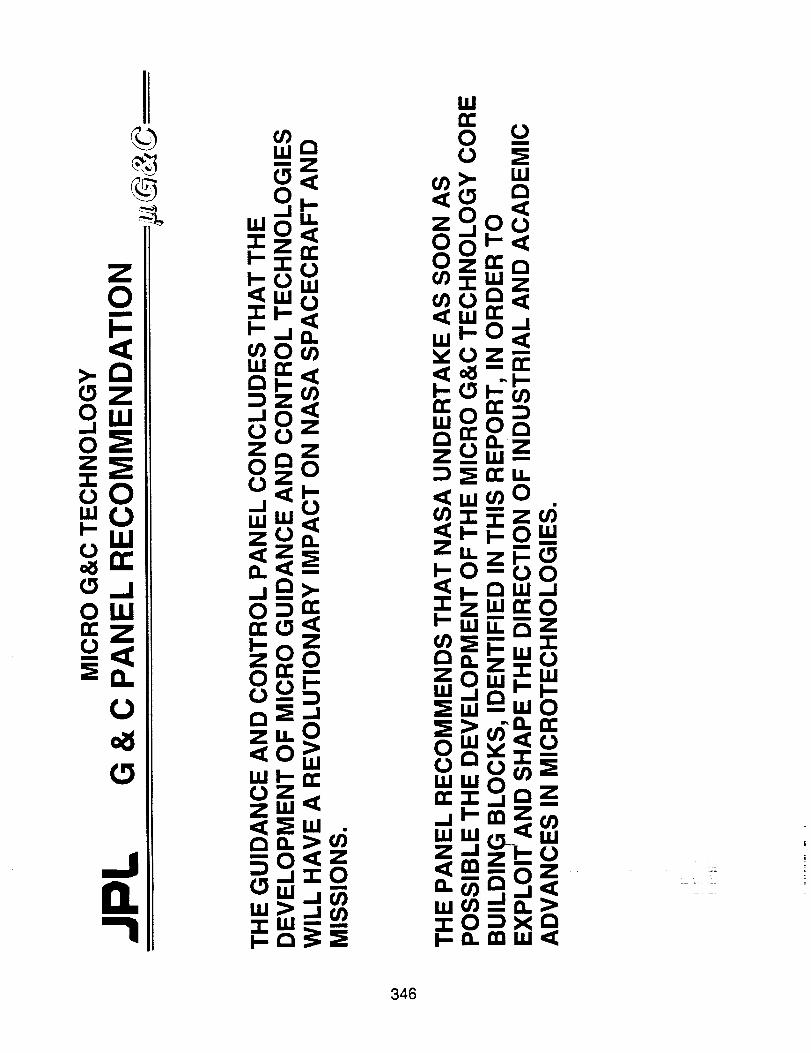
The Guidanceand Control (G&C) Panelconcludedthat the developmentof micro G&Ctechnologieswill have a revolutionary impacton future generationsof NASA spacecraftandmissions. Micro G&C architecturescanbeachievedthroughtheintegrationof mlcromachineddevices,on-chipVLSI circuitry and guidanceandcontrol functions. The corebuilding blocksinclude a six-degree-of-freedommicro inertial measurementunit (IMU), actively controlleddeformablemirrors, distributedmicrosensorsystems,embeddedhealthmonitoring, and light-powered,fault-tolerantprocessingnetworks. The overall recommendationsin the areaof G&Cencompassthreephasesfromtheplanningstagesto theflight experiments:
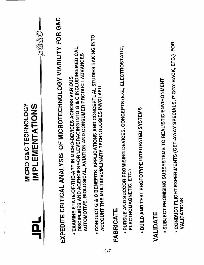
• Expeditecriticalanalysisof microtechnologyviability for G&C:Examineemergingstate-of-the-artmicrodevicetechnologiesacrossvariousdisciplinesandagenciesfor leveraging into G&C implementations,including medical, automotive,biological,aviationandconsumerproductadvances.
- Conductstudiesonmicro G&C conceptualdevelopment,applications,andbenefits,takingintoaccountthemultidisciplinarytechnologiesinvolved.
• Developandfabricatecomponents& systems:- Pursueandsuccorpromisingconceptsanddevices,e.g.electrostatic,electromagnetic,etc.- Build andtestprototypeintegratedsystems.
• Validatesystemperformance:Subjectpromisingsubsystemsto realisticenvironmentsandoperatingconditions.Conductflight experimentsfor validation,e.g."get-awayspecials,""piggy-back,"etc.
Miniaturizationof planetaryroverswill enablea wide rangeof future planeta_ explorationmissions.Roverscanbeconsideredplanetarysurface"spacecraft,"andmuchof thediscussioninthe spacecraftsectionappliesequally to rovers. Therearealso someadditional requirements,primarily in the areasof motility, including pathplanningand navigation,and articulation ofcomponents.Enhancedautonomyis alsodesirable,which requiresadditionalmicrosensorsandon-boardprocessingcapabilities.
35O
The implementation of microtechnologies in sensors and science instruments is already underway, and represents a rapidly evolving area of development with the promise of additionalrevolutionary advances in the future. The primary impact on science instrument size is expected toresult from the development of micromachined transducers, micromechanical structures, and chip-
level photonics coupled with fiber optics. The integration of electronics, photonics, andmicromechanical functionalities into "instruments-on-a-chip" will provide the ultimate size
advantage. The near-term advantages will most likely occur through the insertion ofmicromachined sensors and actuators, on-focal-plane electronics, discrete photonic components,and nanofabricated optical elements. Overall, the Science Instruments Panel of the workshopfound reason for excitement in the potential of emerging microtechnologies to significantly reducethe size and power of future science instruments. Just as in the microelectronics revolution of the
previous 20 years, during the next 20 years we may witness vast reductions in the cost of mass-produced items, in this case based on mlcromechanical and integrated MEMS technologies. This isparticularly encouraging as we enter a future in which we anticipate significantly smaller missionswith concomitantly reduced cost ceilings. Consequently, this panel strongly urged NASA to focusattention on the development of these technologies to permit their insertion into space missions asrapidly as possible.
NEW CAPABILITIES AND ENHANCED PERFORMANCE
In many cases, the insertion of microtechnolog.ies and/or miniaturized systems can actuallyimprove system performance or even enable new science returns. In the case of microspacecraft,for example, the smaller mass and potentially increased robustness against higher accelerations,can be translated into increased maneuverability. This can mean more direct trajectories and shorter
trips, which, in turn, reduces restrictions on the viability of instruments suffering from limitedcomponent lifetimes. It also increases the possibilities for multi-destination missions. Enhancedperformance may also be possible for individual spacecraft subsystems such as communications,data management, G&C, and embedded sensor systems, which could be used to advantage inmicro and conventionally sized spacecraft alike. Micromechanical structures are particularlypromising for improving the capabilities of inertial sensors and robotic manipulators.
Increased sensitivity, frequency response, dynamic range, resolution and robustness can often
be achieved in science sensors through the use of microtechnologies. One of the key co.m.ponentsis the micromachined transducer. A prime example is the tunnel sensor, an ultra-sensmve newtransducer based on electron tunneling between a micromachined tip positioned a few/_ above an
underlying surface, the entire structure fabricated from a single silicon wafer. Reconfigured as atransducer, tunneling structures can reveal changes in the tip-surface separation with accuracies of0.1 /X, or better, representing an increase in sensitivity of many orders of magnitude overconventional transducers. Nanofabricadon and lithographically defined transducer structures offerlarge enhancements in sensitivity over conventional approaches. Microchemical sensors offer thepossibility of in-situ chemical sensing. A second technology area of critical importance to futurescience instruments is the application of micro and nanofabrication techniques to optics and opticalsystems. Microactuators will play a key role in advanced optical systems. Micromachiningtechniques offer significant enhancements in X-ray imaging resolution, and new opportunities inelectrostatic imaging and vacuum electronics for chip-level particle detection and analysis.
Nanolithography of optical surface structure is another key element. Lithography on the nm scaleis also required for the fabrication of high-frequency receiver components, phased-array antennasand chip-level photonic devices.
DISTRIBUTED SYSTEMS
Perhaps the most stimulating and provocative opportunities for new mission capabilities andscience return emerging from the workshop fall into this category. We are at the threshold of theMEMS revolution, anticipated to have as far-reaching an impact on the miniaturization and costreduction of components as the microelectronics revolution we have already experienced. With the
351

availability of mass-produced, miniature instrumentation comes the opportunity to rethink ourfundamental measurement paradigms. It is now possible to expand our horizons from a singleinstrument perspective to one involving multi-node or distributed systems. As the largest departurefrom conventional approaches, advances in this area are the hardest to predict, but may be the most
far-reaching.
Given the possibility of launching suites of microspacecraft, it is appropriate to consider thebenefits of multi-spacecraft missions. Advantages for Eos-type missions include simultaneousmulti-swath mapping. Placing two or more satellites at appropriately phased intervals in the sameorbit enables direct active measurements through the atmospheric layers of interest. Multiple
spacecraft can also be used as nodes along an extended interferometric baseline, or as points of agigantic linear unfilled aperture array. Distributed sensor systems offer performance advantages inhealth management for conventional and microspacecraft. The greatestimpact is expected for fuel
and propulsion systems, G&C systems and life-support systems, which will require thedevelopment and insertion of physical, chemical and biological sensors. Propulsion and fuelsystems would benefit from suites of temperature, pressure and specific chemical sensors for leakdetection.
One of the most exciting ideas that emerged from the workshop is the concept of utilizingdistributed sensor systems for extending the scope of possible science measurements. Similar tothe breakthrough in science return offered by focal-plane arrays versus discrete detector elements,distributed arrays of sensors can provide extended sets of information that lead to new levels ofunderstanding of the underlying phenomena. Multi-node sensor systems enable bothimaging/mapping activities, as well as the acquisition of time-phased/dynamic informationunavailable from a single-sensor measurement mode. For example, while a single seismometercan only indicate the local ground acceleration, multiple sensors distributed across the planetarysurface can lead to a detailed understanding of global seismic activity and the nature and structureof the planetary interior. Examples of science instruments where the advantages of distributedarrays are on the horizon include seismometer arrays, flee-flying magnetometers, planetary surfaceconstituent analysis, and fiber-optic-linked, free-space interferometers. Complex scienceinstruments may also benefit from embedded arrays of microsensors to monitor their system
functionality.
MICROTECHNOLOGY DEVELOPMENT RECOMMENDATIONS
An integrated assessment of the panels sug.gests that the predominant near-term impact ofmicrotechnologies on NASA space missions Is most likely to occur in two areas: (i) theimplementation of miniature systems utilizing existing technology; and (ii) the insertion ofmicromachined sensors and actuators. The miniaturization of spacecraft, planetary rovers and
science instruments can proceed rapidly with the incorporation of miniature technologies that havealready been developed at the component level, but not yet integrated into appropriately designed
miniature systems. - Compact packaging technologies will alsb-/iss_st in this process. Newminiaturization opportunities are offered by emerging micromachined sensors and actuators,selected chemical sensors, discrete photonic devices, and lithographically defined micro-optics
technologies.
Further miniaturization and performance enhancement of spacecraft, planetary rovers and
science instruments will be possible as the on-chip integration of mjcromechanical and electroniccomponents becomes feasible. Coupled with the development of appropriate processing networks,this should enable the first distributed sensor systems for health management applications. Other
important mid-term impact areas include the incorporation of binary and adaptive optics and thedevelopment of space-qualifiable high-speed electronic systems for Ka-band communications andadaptive processing networks. More fundamental advances are likely to provide additional systemadvantages further downstream. To ensure that areas relevant to space applications emerge in atimely manner, it is recommended that NASA consider base-program support in selected areas of
352
long-term pay-off. These include micromachining and nanofabrication techniques of greatersophistication and in new materials including binary optics, chemical and biological microsensordevelopment, vacuum electronics components, integrated photonic technologies, and fundamentaladvances in concurrent processing architectures.
CONCLUSIONS
As the first forum spanning the emerging microtechnologies and bringing together thetechnology and space systems experts across the country, the workshop was enthusiasticallysupported by all parts of the community. Over 225 people participated in this workshop, drawnfrom universities, industry, NASA centers, and other government laboratories and agencies. Theworkshop was chaired by Fred Hadaegh, Bill Kaiser and Barbara Wilson, with presentationsoverviewing emerging microtechnology developments coordinated by Frank Grunthaner.Following the workshop, a set of recommendations to NASA in support of the key technologydevelopment areas was generated as an interim internal report, which was subsequentlyincorporated into the NASA technology planning process.
353


Microtechnologies
and
Applications to Space Systems Workshop
APPENDIX
_NG P_GE BLANK NOT F_ED
355

!
ii
!i

MICROTECHNOLOGIESAND APPLICATIONS TO SPACE SYSTEMS WORKSHOP
AGENDA
DAY h May 27, 1992
WELCOME - Barbara Wilson, Session Chair
8:00 am Workshop Welcome
8:15 am Workshop OverviewTerry Cole, JPL
Wayne Hudson, NASA Code RS
FUTURE VISIONS - Gordon Johnston, Session Chair
8:30 am Future Trends in Small Missions and Need for Microtechnology
8:50 am The NSF Microtechnology Program, or Robots on the Head of a Pin
9:20 am Silicon Micro-Instrumentation
Charles Elachi, JPL
George Hazelrigg, NSF
Kurt Petersen, Lucas NovaSensor
NASA MISSION & SCIENCE GOALS - Wayne Hudson, Session Chair
10:10 am The Solar System Exploration Program: Goals, Strategy, and Plans
10:30 am Science Goals & Constraints of MESUR
10:50 am The Fast Flyby Pluto Mission: Completing the Reconnaissanceof the Solar System
1 l:10 am Space Physics Mission Needs
11:30 am Mission & Science Goals of Lunar Outpost Missions
Corinne Buoni, SAIC
Arthur Lane, JPL
Paul Henry, JPL
Jim Randolph, NASA Code SS
Jeffrey Plescia, JPL
MICROTECHNOLOGY PROGRAM OVERVIEWS PART I - Frank Grunthaner, Session Chair
1:00 pm
1:20 pm
1:50 pm
2:10pm
2:30 pm
2:50 pm
3:10 pm
Micro Electro Mechanical Systems (MEMS) and Their Impacton Future Robotic Systems
SDI Development of Miniaturized Components
DoD Advanced Space Technology Program Challenge
Code R Microtechnologies
Micromechanics Program at Sandia: Micromechanical Sensors,Actuators and Devices
Micromanufacturing : Recent Developments in this Countryand Abroad
Microsensors and Microinstruments: New Measurement Principlesand New Applications
Stephen Jacobsen, Univ. of Utah
Mick Blackledge, SDI/TN
AI Wheatley, DARPA
Dave Lavery, NASA Code RS
Ned Godshall, Sandia
Robert Warrington, LouisianaTech Univ.
William J. Kaiser, JPL
MICROTECHNOLOGY PROGRAM OVERVIEWS PART H - William Kaiser, Session Chair
5:00 pm
5:20 pm
5:40 pm
6:00 pm
6:20 pm
Micro-Sensors, -Actuators, -Systems: Accomplishments& Prospects
National A[anofabrication Facility and Nanoelectromechanics
Microactuator Production via High AsPect Ratio, Edge AcuityMetal Fabrication Technology
Overview of Microoptics: Past, Present and Future
Microsensors, Smart Sensors, Sensor Arrays, and the Artificial Nose
Richard White, UC Berkeley
Noel MacDonald, Comell Univ.
Henry Guckel, Univ. ofWisconsin-Madison
Wilfrid Veldkamp, LincolnLaboratory, MIT
Joseph Stetter, TransducerResearch Inc.
P_ PA'_IE BLANK NOT F_,.I_;E_
357

DAY 2; May 28. 1992
APPLICATIONS OVERVIEWS PART I - John DiBattista, Session Chair
8:00 am Micromechanical Actuators
8:30 am In Situ Meteorological Sensors for Earth and Mars Applications
8:50 am
9:10 am
9:40 am
Silicon Flexural Microelectromechanical Devices
Micromachining the Future
Learning from Biology - Motor Systems at all Scales
APPLICATIONS OVERVIEWS PART H - Fred Hadaegh, Session Chair
10:20 am Micro-Software for Micro-Robots
10:40 am Spacecraft Telecommunications Technology for Microspacecrafi
11:00 am Microspacecraft: A Concept
11:20 am Micro-Guidance and Control Technology Overview
11:40 am Health Management Issues for Space Systems
William Trimmer, PrincetonUniv. & Belle Mead Research
James Tillman, Univ. of
Washington
Kaigham Gabriel, NRL
Marc Madou, Teknekron
M.G. Littman, Princeton Univ.
David Miller, MIT
Charles Kyriacou
Ross Jones, JPL
Glen Kissel, JPL
Stephen Johnson, MartinMarietta Astronautics
PARAI,LEL SESSION ON SCIENCE INSTRUMENTS
SESSION AND PANEL CHAIRS: Benton Clark, Gregg Vane & Louis Watts
1:00 pm
1:20 pm
1:40 pm
2:00 pm
2:20 pin
2:40 pm
3:00 pm
3:40 pm
4:00 pm
4:20 pm
4:40 pm
5:00 pm
Trends in X-Ray Fluorescence Instruments
Miniaturization in X-Ray and Gamma-Ray Spectroscopy
Backscatter Mossbauer Spectrometer (BaMS) for Extraterrestrial
Applications
A Sub-cm Micromachined Electron Microscope
Differential Scanning Calorinuetry for Planetary Surface Exploration
Micro-Sensors for in-situ Meteorological Measurements
A Broad-Band Microseismometerfor Planetary Applications
The Miniature X-Ray Telescope ALEXIS
Imaging Spectrometry for the Earth and Other Solar System Bodies
Smart Focal-Plane Technology for Micro Instruments and MicroRovers
Evolution of Miniature Detectors and Focal Plane Arrays forInfrared Sensors
Photonics Devices for Microinstruments
Benton Clark, Martin Marietta
Jan Iwanczyk, Xsirius, Inc.
David Agresti, Univ. ofAlabama
Alan Feinerman, Univ. of
Illinois at Chicago
Douglas Ming, JSC
David Crisp, JPL
Bruce Banerdt, JPL
Bill Priedhorsky, Los Alamos
Gregg Vane, JPL
Eric Fossum, JPL
Louis Watts, SAIC
Robert Lang, Spectra Diode
PARALLEL SESSION ON M!CROSPACECRAFT
SESSION AND PANEL CHAIRS: Denis Connolly, Ross Jones
1:00 pm Asteroid Investigation with Microspacecraft (AIM)
1:20 pm
1:40 pm
2:00 pm
2:20 pm
2:40 pm
3:20 pm
Fundamental Limits on Earth Remote Sensing from Small Spacecraft
Development of MMIC Technology for SATCOM Applications
Spacecraft Teleco_unications Technology for MicrospacecraftApplications_ _ _
Power Subsystem State-of-the-Art Assessment and MiniaturizationTechnology Needs
The Application of Micro Technology to Spacecraft On-Board
Computing
Command & Data Subsystem Technology
Ross Jones & ChristopherSalvo, JPL
David Rider, JPL
John Berenz, TRW
Charles Kyriacou, JPL
Robert Detwiler, JPL
Leon Alkalaj, JPL
Richard Grammier, JPL
358

3:40 pm
4:00 pm
4:20 pm
4:40 pm
5:00 pm
Electronic Packaging for Microspacecraf1,4pplications
Microspacecrafl Attitude Control
Miniaturized Propulsion Systems
Lightweight Structures and Mechanisms for Microsatellites
SDI Flight Tests of Integrated Microsystems
David Wasler, JPL
George Sevaston, JPL
Dale Hook, TRW
Robert Wendt, Martin Marietta
Rich Matlock, SDI/'I'N
PARALLEL SESSION ON SPACE STATION, SHUTrlLE & PROPULSION
SESSION AND PANEL CHAIRS: W.T. Powers, Gerald Voecks
1:00 pm- 6:00 pm Roundtable Discussions and presentations
PARALLEL SESSION ON MICROROVERS
SESSION AND PANEL CHAIRS: Kaigham Gabriel and Subramani Venkataraman
1:00 pm
1:25 pm
1:50 pm
2:15 pm
2:40 pm
3:05 pm
3:50 pm
4:15 pm
4:40 pm
5:05 pm
5:30 pm
Role of Microrovers in Planetary Exploration
Robotic Vehicles for Planetary Exploration
Application of Behavior Control Technology to Planetary Rovers
Difficulties Inherent in Miniaturizing Current Rover Technologiesfor Use as Planetary Explorers
Micromachining Technologies for Automotive Applications
Microtechnology on Minirovers
Silicon Flexural Microelectromechanical Devices
Micromechanical Actuators
Toward Milli-Newton Electro- and Magneto-Static Microactuators
Micro Structures and Micro Actuators for ImplementingSub-Millimeter Robots
Coordinated Control of Legged Locomotion via NonlinearOscillators
Corinne Buoni, SAIC
Brian Wilcox, JPL
Rajiv Desai, JPL
Gerald Roston, CMU
William Tang, Ford Motor
Donald Bickler, JPL
Kaigham Gabriel, NRL
William Trimmer, PrincetonUniv. & Belle Mead Research
Long-Shen Fan, IBM Almaden
Ronald Fearing, UC Berkeley
P. Krishnaprasad, Univ. ofMaryland
PARALLEL SESSION ON MICROTECtLNOLOGIES OF THE FUTURE
SESSION AND PANEL CHAIRS: Frank Grunthaner, John Hines and Brent Mott
1:00 pm - 6:00 pm Roundtable Discussions and presentations
PARALLEL SESSION ON GUIDANCE & CONTROL
SESSION AND PANEL CHAIRS: John DiBattista, Fred Hadaegh and Claude Keckler
1:00 pm Control of Micro-Machined Deformable Mirrors
1:25 pm Emerging Technologies in Microguidance and Control
1:50 pm
2:15 pm
2:55 pm
3:20 pm
3:45 pm
4:10 pm
4:35 pm
An Electrostatically Suspended, Micro-Mechanical RateGyroscope
GEC Ferranti Piezo Vibratory Gyroscope
The Application of Micromachined Sensors to Manned SpaceSystems
Micro Guidance and Control Synthesis: New Components,Architectures and Capabilities
Microoptomechanical Devices & Systems using EpitaxialLi_-Off
Miniature Wide Field-of-View Star Trackers for SpacecraftAttitude Sensing & Navigation
Novel Position Sensor Technologies for Micro Accelerometers
P.K.C. Wang, UCLA
Marc Weinberg, C.S. DraperLaboratory
Timothy Hawkey, SatconTechnology Corp.
John Nuttall, GEC Ferranti
Gary Havey, Honeywell Systems& Research
Edward Mettlef, JPL
Mark Alien, Georgia Inst. ofTechnology
William McCarty, OCA AppliedOptics, Inc.
Thomas Van Zandt, JPL
359

WORKSHOP PANELS
Arden Albee, Caltech
James Bradley, JPLBenton Clark, Martin Marietta
Eric Fossum, JPL
Leon Alkalaj, JPLJohn Berenz, TRWCorinne Buoni, SAIC
Richard Cheng, ttughes
Denis ConnoUy, LeRCRobert Detwiler, JPL
Terry Gamber, Martin Marietta
PANEL ON SCIENCE INSTRUMENTS
PANEL CHAIRS: Benton Clark, Gregg Vane & Louis Watts
PANEL MEMBERS
Raymond Goldstein, JPL Gregg Vane, JPLGordon Johnston, NASA Code RSS Wilfrid Veldkamp, MIT Lincoln Labs
William Kaiser, JPL Louis Watts, SAIC
James Tillman, Univ. of WA
PANEL ON MICROSPACECRAFT
PANEL CHAIRS: Denis Connolly, Ross Jones
PANEL MEMBERS
Rick Grammier, JPLDale Hook, TRW
Ross Jones, JPL
Charles Kyriacou, JPL
Robert Lafferty, MotorolaRich Matiock, SDIfI'N
John Mdver, Boeing
Rich Reinert, Ball Aerospace
George Sevaston, JPLDave Stevens, JPL
David Wasler, JPL
Robert Wendt, Martin Marietta
PANEL ON SPACE STATION, SHUTTLE & PROPULSION
PANEL CHAIRS: W.T. Powers, Gerald Voecks
_" PANEL MEMBERS
David Blackburn, NIST
Rod Bogue, Ball AerospaceThurman llenderson, U. of Cincinnati
Richard Higgins, GA Tech Res. Inst.
Stephen Johnson, Martin Marietta
Kevin Kellenberger, KSC
C.C. Liu, Case Western ReserveWally Parce, Molecular DevicesMarc Porter, Iowa State Univ.
Greg Schunk, MSFC
PANEL ON MICROROVERS
John Simpson, RocketdyneRaoul Tawel, JPL
W.T. Powers, MSFC
Dave Venezky, NRLGerald Voecks, JPL
PANEL CHAIRS: Kaigham Gabriel and Subramani Venkataraman
PANEL MEMBERS
Rajiv Desai, JPL Dave Lavery, NASA Code RS Subramani Venkataraman, JPL
Long-Shen Fan, IBM, Almaden Michael Sims, ARC Brian Wilcox, JPL
Kaigham Gabriel, NRL Bill Tang, Ford Scientific Res. Lab.
PANEL ON MICROTECItNOLOGIES OF THE FUTURE
PANEL CHAIRS: Frank Grunthaner, John Hines and Brent Mott
Robert Hughes, Sandia
Stephen Jacobsen, Univ. of Utah
Seun Kahng, LaRC
Thomas Kenny, JPLNed Godshall, Sandia
Frank Grunthaner, JPL
PANEL MEMBERS
John Hines, ARCMark Madou, TeknekronM. Mehregany, Case Western Res.
Harvey Moseley, GSFCBrent Mort, GSFCKurt Petersen, Lueas NovaSensor
Stephen Senturia, MIT
Joseph Stetter, Transducer ResearchYu-Chong Tai, Caltech
Joseph Warner, LeRCRobert Warrington, LSU
Richard White, UC Berkeley
PANEL ON GUIDANCE & CONTROL
PANEL CHAIRS: John DiBattista, Fred Hadaegh and Claude Keckler
PANEL MEMBERS
Randy Bartman, JPLFrank Bauer, GSFC
John DiBattista, NASA Code RSRNelson Groom, LaRC
Fred Hadaegh, JPL
Gary Havey, JSCDean Jacot, BoeingClaude Keclder, LaRCGlen Kissel, JPL
Henry Lure, Jr., ARC
John Shackelford, General
DynamicsHenry Waites, MSFC
360

I
1. Report No. 93-8 j2 Government Accession No.|
4. Title and Subtitle
Proceedings of the Workshop on Microtechnologies
and Applications to Space Systems
TECHNICAL REPORT STANDARD TITLE PAGE
3. Recipient's Catalog No.
5. Report DateJune 15, 1993
6. Performing Organization Code
7. Author(s) 8. Performing Organization Report No.None credited on cover
9. 10. Work Unit No.Performing Organization Name and Address
JET PROPULSION LABORATORY
California Institute of Technology4800 Oak Grove Drive
Pasadena, California 91109
2. Sponsoring Agency Name and Addre.
NATIONAL AERONAUTICS AND SPACE ADMINISTRATION
Washing%on, D.C. 20546
11. Contract or Grant No.
NAS7-918
13. Type of Report and Period Covered
JPL Publication
14. Sponsoring Agency CodeRE 156 BK-506-49-21-00-00
15. Supplementary Notes
16. Abstract
During FY'92, the NASA Code RS System Analysis RTOP funded a study to evaluate the
potential impact of emerging microtechnologies on future space missions. As part of this study, aworkshop, "Microtechnologies and Applications to Space Systems_' was held May 27-29th, 1992,in Pasadena, CA. This volume serves as the Proceedings of this workshop. It contains the
manuscripts provided by plenary and parallel session presenters, and summary reports generatedfrom this material and from information presented during the panel discussions. Where
manuscripts were not provided, extended abstracts, if available, have been included. The order of
the papers follows the original workshop agenda.
17. Key Wor_ (Selected by Author(s))
Spacecraft Communications, Command,
and Tracking
Spacecraft Design, Testing, andPerforman:e
Spacecraft Instrumentation
Spacecraft Propulsion and Power
19. Security Cl_sif. _f thls report) 20. Securffy Cl_sif. _f this page)
Unclassified Unclassified
18. DistributionStatement
Unclassified; unlimited.
21. No. of Pages
37O
22. Price
JPL. 0184 Ft9183
