naca research memorandum - nasa rm e551,14a national advisory committee for aeronautics research...
TRANSCRIPT
.t'(IVl 1i5L14a
NACA
RESEARCH MEMORANDUM
VISUAL STUDY OF FREE CONVECTION IN A NARROW
VERTICAL ENCLOSURE
By Ephraim M. Sparrow and Samuel J. Kaufman
Lewis Flight Propulsion Laboratory Cleveland, Ohio
NATIONAL ADVISORY COMMITTEE FOR AERONAUTICS
WASHINGTON February 16, 1956
https://ntrs.nasa.gov/search.jsp?R=19930089006 2018-07-13T22:25:02+00:00Z

NACA RM E551,14a
NATIONAL ADVISORY COMMITTEE FOR AERONAUTICS
RESEARCH MEMORANDUM
VISUAL STUDY OF FREE CONVECTION IN A NARROW VERTICAL ENCLOSURE
By Ephraim M. Sparrow and Samuel J. Kaufman
SUMMARY
The free-convection flow of water in a narrow vertical enclosure, cooled at the top through a copper surface and open at the bottom to a heated reservoir, has been studied by means of a shadowgraph. It was found that there is no flow pattern which is steady with time, that is, no region of the enclosure is permanently a region of upflow or of down-flow. Because of variations in the size of the various upflow and down-flow regions arranged along the length of the enclosure at a given time, and because of changes with time, neither upflow regions nor downflow regions could be characterized by a definite size. The number of up-flow and downflow regions varied with time.
The dominating characteristics of the flow patterns were instability and change.
INTRODUCTION
An experiment on free convection of liquid sodium in a thin annu-lus of large mean diameter has been reported in reference 1. The annu-lus, which was oriented with its axis vertical, was closed at the top by a surface through which heat was extracted. The bottom of the annu-lus was open to a reservoir of heated liquid sodium. Temperature meas-urements were taken around the periphery of the annulus. From these data the existence of alternate regions of "upflow" and downflow, ar-ranged in a regular way around the circumference, was inferred. Not only could it be inferred that the alternate upflow and downflow regions were uniform in size, but also that the flow pattern, once established, did not change. That is, downf low regions always remained as downflow regions and upflow regions always remained as upflow regions.
The present investigation was undertaken to determine by visual ob-servation-the details of the flow in a system similar to the one de-scribed above. In order to obtain an apparatus suited for flow visuali-zation by optical techniques, a number of departures from the system of reference . 1 were required. A rectangular enclosure was used instead of

NACA RN E55L14a 2
an annulus. However, the basic situation of heat extraction through a surface at the top and free exchange with a heated reservoir at the bot-tom was maintained. Distilled water was used as the working fluid rather
than liquid sodium.
The extraction-of heat at the top surface of the enclosure (or .annu-lus) gives rise to a layer of fluid, in the region of the top, which is relatively heavier than the warmer fluid below. The heavier fluid, when accumulated in sufficient quantity near the top, will push its way down-ward through the enclosure. The warmer, lighter fluid will rise to take the place of the descending cool fluid.. So, regions of upflow and down-flow are established. The details of the flow to be determined from a visual inspection are (1) the steadiness of the flow patterns with time, (2) the size and uniformity of the various . upflow and downflow regions, and (3) the direction of flow velocities with particular attention to nonvertical components. Further, the visual observation provides an in- sight into both the initiation and the breakdown of a particular flow
pattern. - -
APPARATUS
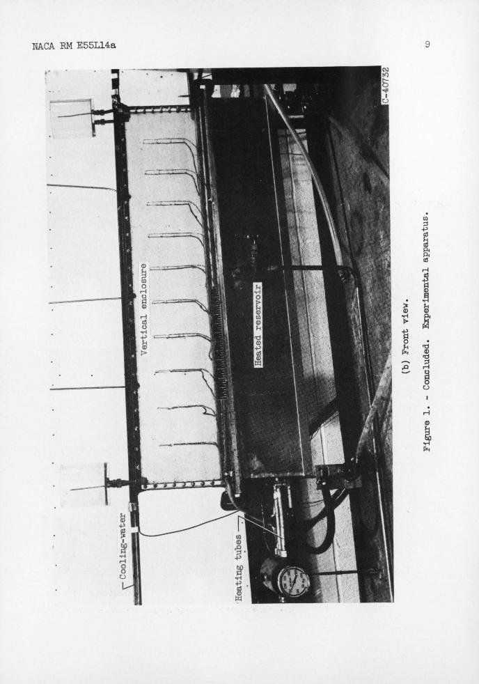
• The description of the experimental apparatus will be augmented by the photographs-of figure 1. An oblique view showing an over-all view of the experimental apparatus is shown in figure 1(a). A front view of the test section on which the important components have been labeled is shown in figure 1(b). -
The vertical enclosure, in which free-convection flow patterns were observed, had front and rear walls made of sheets of Plexiglas. The top wall of the -enclosure was a solid strip of copper; the end walls were made of Plexiglas strips. The enclosure, which was open at the bottom, was joined to a reservoir of heated fluid. The vertical enclosure was
9. inches-high, 44 inches long, and . 3/16 inch thick. The ratio of
height to thickness was therefore about 50 to 1. - - - - -
Heatwas extracted from the -fluid at the top of the enclosure through the copper-wall that was soldered to a duct through which cool-ing -water was passed. The fluid in the reservoir at the bottom was heated by three tubes that ran the length of the reservoir through which hot water was passed. During the operation of the apparatus, both the - reservoir and the enclosure were completely filled with distilled water. Because of the free-convection motion, -there was a continual exchange of fluid between -the reservoir and the enclosure. --
The apparatus was operated for several hours before observations were made in order to insure the disappearance of initial transients.

NACA RN E55L14a 3
Flow patterns were studied for temperature differences between the res-ervoir and the copper strip at the top Of the enclosure in the range from 5Q0 to 85° F.
INSTRUMENTATION
The motion of the fluid was viewed by means of a shadowgraph. A point source of light was placed in front of the enclosure as shown in figure 1. Light rays passed through the front wall, the 3/16-inch gap thickness, and the rear wall of the enclosure. The shadow-pattern was viewed on a screen behind the apparatus. The shadowgraph picture was, therefore, a two-dimensional picture, which provided information on flow patterns in a plane parallel to the front (or rear) wall. No informa-tion could be obtained about flow normal to front and rear walls.
The strongest delineation of the shadow lines occurs where the den-sity gradients change most rapidly. The temperature and density of the hot fluid rising from the reservoir is fairly uniform. Hence, little evidence of the rising stream is seen except where it contacts the cooler, denser fluid. On the Other hand, the cooling at the top of the enclosure creates nonuniformities in temperature and, hence, variations in density gradient are induced. The moving shadow lines, which are ob-served in the shadowgraph picture are associated with density gradients which are carried along-with-the movement of the cooled, heavier fluid. A photograph of a shadowgraph will not show the motion of the shadow lines, only their instantaneous location. In interpreting the photo-graphs of shadbwgraphs (section • Shadowgraph Photographs), the presence of the shadow lines in a region of a photograph should be taken as in-ferring motion of cooled, heavier fluid in the region.
Thermocouples were installed in the front and rear walls of the en-closure to provide supplementary information about the flow pattern. The thermocouple tips were 1/32 inch from the surface of the enclosure. This was the minimum distance at which thermocouples could be installed without giving rise to bumps on the wall of the enclosure.
Shadowgraph Photographs
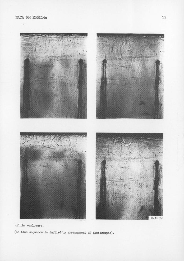
Photographs of some shadowgraphs are shown in figure 2. The dy-namics of the flow, which cannot be learned from photographs, will be discussed in the Flow Dynamics section using the information obtained from long-time - observation of the flow. -
The eight photographs shown in figure 3(a) cover an area 6 inches
high by 5 inches wide located about one-half the length of the enclosure.
4 NACA RN E551,14a
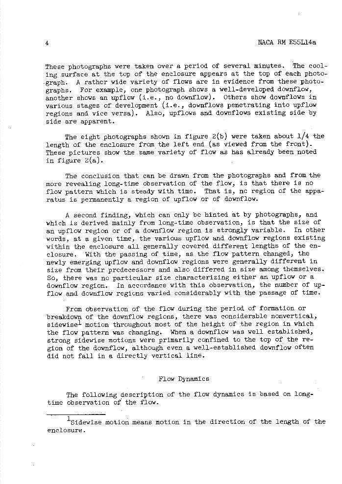
These photographs were taken over a period of several minutes. The cool-ing surface at the top of the enclosure appears at the top of each photo-graph. A rather wide variety of flows are in evidence from these photo-graphs. For example, one photograph shows a well-developed downflow, another shows an upflow (i.e., no downflow). Others show downf lows in various stages of development (i.e., downflows penetrating into upflow regions and vice versa). Also, upflows and downflows existing side by side are apparent.
The eight photographs shown in figure 2(b) were taken about 1/4 the length of the enclosure from the left end (as viewed from the front). These pictures show the same variety of flow as has already been noted in figure 2(a).
The conclusion that can be drawn from the photographs and from the more revealing long-time observation of the flow, is that there is no flow pattern which is steady with time. That is, no region of the appa-ratus is permanently a region of upflow or of downf low.
A second finding, which can only be hinted at by photographs, and which is derived mainly from long-time observation, is that the size of an upflow region or of a downflow region is strongly variable. In other words, at a given time, the various upflow and downflow regions existing within the enclosure all generally covered different lengths of the en-closure. With the passing of time, as the flow pattern changed, the newly emerging upflow and downf low regions were generally different in size from their predecessors and also differed in size among themselves. So, there was no particular size characterizing either an upflow or a downflow region. In accordance with this observation, the number of up-flow and downflow regions varied considerably with the passage of time.
From observation of the flow during the period of formation or breakdown of the downflow regions, there was considerable nonvertical, sidewise- motion throughout most of the height of the region in which the flow pattern was changing. When a downflow was well established, strong sidewise motions were primarily confined to the top of the re-gion of the downf low, although even a well-established doimflow often did not fall in a directly vertical line.
Flow Dynamics
The following description of the flow dynamics is based on long-time observation of the flow.
1Sidewise motion means motion in the direction of the length of the enclosure.

NACA RN E55L14a 5
The cooling of fluid at the top of the enclosure gives rise to a continuous generation of relatively heavy fluid. Heavy fluid generated above an upflow region which is located near a downflow region may move sidewise along the top of the enclosure until it reaches the downflow region. When it reaches the downflow region, the sidewise-moving fluid is turned in an almost vertical direction. A downflow fed by fluid en-tering it in this fashion is funnel-shaped in appearance; and the down-flow region may be regarded as a funnel through which the heavy fluid generated in a given region escapes from the top surface. Heavy fluid generated above an upflow region that is farther from a downflow region may also feed into the nearest downf low region. However, the amount of heavy fluid accumulated during the longer path of sidewise flow may often be sufficient to push downward. In this circumstance, the sidewise mo-tion of the heavy fluid to the nearest downflow region takes place in a band (several inches in height) below the top of enclosure, as well as at the top itself. 01 course, these descriptions are generalizations. Sometimes the strength of the upflow is sufficient to confine sidewise moving fluid, generated above a region of upflow, to a small layer near the top of the enclosure, even though the sidewise movement may be over a relatively long path. Alternately, some "chunks" of heavy fluid carry out a sidewise movement below the top layer even though their path of travel is short.
On some occasions, heavy fluid, generated above an upflow region, does not follow an existing path of descent. (For example, the nearest established dowaflow may be too far away.) Under these circumstances, the heavy fluid generated continues to accumulate above the upflow re-gion. Finally, chunks of heavy fluid force downward. There are three possible endings to this attempted downward movement. One possibility is that the downward-moving chunks of cooled fluid, reinforced by addi-tional heavy fluid from above and also from adjacent regions, reach the reservoir at the bottom. This initial descent is often accomplished haltingly and with considerable nonvertical flow. Whether or not the downflow path thus established is sustained depends upon the supply of additional heavy fluid from adjacent regions near the top of the enclo-sure. A second possibility is that descending chunks, stopped in any downward motion because of the opposition of the rising hot fluid, are pushed sidewise and reinforce the efforts of adjacent chunks of cooled fluid which are descendingslowly. The third possibility is that de-sending chunks of cooled fluid are repelled by the rising stream and are driven sidewise into an already established downflow.
A downflow continues only as long as there is sufficient cool, heavy fluid to supply it. If the rate of removal of the cooled fluid exceeds its rate of production, the downflow may cease. Alternately, the downflow may move sidewise into a region . (previously occupied by an upflow) in which the supply of cooled fluid (located along the top of the enclosure) is sufficient to sustain it. .. .

6 NACA RN E551,14a
The nature of the observed flow patterns did not change as the tem-perature difference between the heated reservoir and the cooling.surface at the top of the enclosure was varied. The notable effect was a lessen-ing of the flow velocities as the temperature difference was diminished.
There was evidence of end effects associated with both left- and right-hand end walls of the enclosure. An almost continuous downflow took place ma 3/4-inch band adjacent to both of these walls. However, at a distance of 4 inches from either end wall, the flow patterns ob-served were similar to those that were seen very far from these walls.
Wall-Temperature Data
Thermocouples were installed in the front and rear walls of the en-closure to detect the presence of a spatial temperature pattern which would correspond to a permanent group of upflow and downflow regions.
A representative plot of the temperature on the front wall is shown in figure 3. (The rear-wall temperatures give .a similar plot.) There was little difference in the temperature at all locations. This lack of evidence of a permanent flow pattern is in accord with the visual obser-vations. The thermal inertia of the Plexiglas wall appeared sufficient to smooth any temperature variations with time which might have arisen because of the changing flow pattern.
DISCUSSION
As has - been already mentioned, the experiment reported in reference 1 on free convection in a thin annulus using liquid sodium as the work- ing fluid gave a wall-temperature pattern from which the existence of permanent upflow and downflow regions could be inferred. These results differ from the findings of the present study. There are many differ-ences between the two investigations the influences of whichcannot be clearly evaluated. The most obvious differences are in working fluid and in geometry. An annulus, as thin as that of reference 1, might, at first, be expected to act in a fashion similar to that of a narrow rec-tangularenclosureof the sort used in the present study. However, the lack or presence of end walls may have some not-yet-understood effect on flow stability. The definition of the variables comprising dimen-sionless groups needed to insure dynamic similarity of flows of the type considered here is not at all clear. .
Aside from the unevaluated factors already noted, there is a par-ticular difference between. the apparatus of the two experirments which might explain the apparent contradiction in the findings. The heat sink at the top of the enclosure in-the present investigation was a smooth

NACA RM E55L14a 7
copper surface. In reference 1, the cooling surface at the top of the annulus was sodiun itself., which had "frozen out" during the initial stages of the operation of the system. It seems plausible to expect that the surface thus formed wouldnot .be smooth, but would have hills and valleys corresponding to the. upflow-.downflow pattern which developed during the initial stages of operation.. Such a wavy surface, once de-veloped, would tend to perpetuate permanent upflow-downfloW patterns.
A single photograph of a glass-walled annulus with water as the working fluid in which dye is used to define the streaming of the flow is included in reference 1. Sufficient information can not be obtained from this single photograph toérmit comparison with results of the present investigation.
CONCLUSIONS
The free-convection flow of water in a narrow vertical' enclosure, cooled at the top through a copper surface and open at the bottom to a heated reservoir, has been studied by. means of a shadowgraph. No flow pattern was --found to be steady with time, that is, no region of the en-closure is permanently a region of upflow or of downflow. Because of variations in the size of the various üpflow and downflow regions ar-ranged along the length of the enclosure at a. given time and because of changes with time, neither upflow regions nor -downflow regions could be characterized by a definite size. The number of upflow and downflow re-gions varied with time.
The dominating characteristics of the flow patterns were instabil-ity and change.
Lewis Flight Propulsion Laboratory National Advisory Committee for Aeronautics
Cleveland, Ohio, December 15, 1955
REFERENCE
1. Timo, D. P.: Free Convection in Narrow Vertical Sodium Annuli. KAPL-1082,-Knolls Atomic Power Lab., Geheral Electric Co., Mar. 5, 19.54.(Contract No W-31-109 Eng -52 )

6 N!CA RN E55L14a
CD
P. C5
'-4
H
NACA RN E55L14a

4
i;.
;: (Zv
10
NACA PM E55L14a
irr
* * 'F•;:;
Ito
Le-
I L
L.-O73O
(a) Location,-! the length
Figure 2. - Representative shadow-aph photographs of flow pattern
W. -40731
Vi:i:. " *1 A
1 -• • • - / I
NACA EM E55L14a
11
• •.
.4 •1• : c/
•-.
• j
"I
of the enclosure.
(no time sequence is implied by arrangement of photographs).

-r ; -
12
NACA RM E55L14a
& I I r-40728
(b) Location, the length of the
Figure 2. - Concluded.. Representative shadowaph photographs of flow

-
qw'I
)' II
&
c
rC-40729
NACA RM E55L14a
13
enclosure from the left end.
pattern (no time sequence is implied by arrangement of photographs).

14 WARM E55L14a
fl ji
0)
-0 -0-00 zzH
H. H
HI
00 ) 00
0
CH+)
0 0c0 0
co
0)0) 0p
+) + (I) r4 "'
\0 o 0
rd
IlL
Cd
ED 01.4
CH C')
0) N
00) • 4)
cj 00W-
0bD 0 •H 0.
0 0-0 H
do 4a.Tnqvx@dmoLj
- - -- -. NACA - Langley Field, Va.