nace mr-0103-2007
DESCRIPTION
AN OVERVIEW OF NACE INTERNATIONAL STANDARD MR0103 AND COMPARISON WITH MR0175TRANSCRIPT
Israel H
Standard
Material Requirements
Materials Resistant to Sulfide Stress Cracking in
Corrosive Petroleum Refining Environments
This NACE International standard represents a consensus of those individual members who have reviewed this document, its scope, and provisions. Its acceptance does not in any respect preclude anyone, whether he or she has adopted the standard or not, from manufacturing, marketing, purchasing, or using products, processes, or procedures not in conformance with this standard. Nothing contained in this NACE International standard is to be construed as granting any right, by implication or otherwise, to manufacture, sell, or use in connection with any method, apparatus, or product covered by Letters Patent, or as indemnifying or protecting anyone against liability for infringement of Letters Patent. This standard represents minimum requirements and should in no way be interpreted as a restriction on the use of better procedures or materials. Neither is this standard intended to apply in all cases relating to the subject. Unpredictable circumstances may negate the usefulness of this standard in specific instances. NACE International assumes no responsibility for the interpretation or use of this standard by other parties and accepts responsibility for only those official NACE International interpretations issued by NACE International in accordance with its governing procedures and policies which preclude the issuance of interpretations by individual volunteers. Users of this NACE International standard are responsible for reviewing appropriate health, safety, environmental, and regulatory documents and for determining their applicability in relation to this standard prior to its use. This NACE International standard may not necessarily address all potential health and safety problems or environmental hazards associated with the use of materials, equipment, and/or operations detailed or referred to within this standard. Users of this NACE International standard are also responsible for establishing appropriate health, safety, and environmental protection practices, in consultation with appropriate regulatory authorities if necessary, to achieve compliance with any existing applicable regulatory requirements prior to the use of this standard. CAUTIONARY NOTICE: NACE International standards are subject to periodic review, and may be revised or withdrawn at any time in accordance with NACE technical committee procedures. NACE International requires that action be taken to reaffirm, revise, or withdraw this standard no later than five years from the date of initial publication and subsequently from the date of each reaffirmation or revision. The user is cautioned to obtain the latest edition. Purchasers of NACE International standards may receive current information on all standards and other NACE International publications by contacting the NACE International First Service Department, 1440 South Creek Dr., Houston, Texas 77084-4906 (telephone +1 281/228-6200).
Revised 2007-07-19 Revised 2005-05-23
Approved 2003-03-15 NACE International
1440 South Creek Drive Houston, Texas 77084-4906
+1 281/228-6200
ISBN 1-57590-168-4 © 2007, NACE International
NACE Standard MR0103-2007
Item No. 21305
ernandez Acatitla - Invoice INV-106213-I8GARU, downloaded on 7/9/2008 5:07:24 PM - Single-user license only, copying and networking prohibited.
Israel Herna
MR0103-2007
NACE International i
_________________________________________________________________________
Foreword
This NACE standard defines material requirements for resistance to sulfide stress cracking (SSC) in sour refinery process environments, i.e., environments that contain wet hydrogen sulfide (H2S). It is intended to be utilized by refineries, equipment manufacturers, engineering contractors, and construction contractors. The term ―wet H2S cracking‖ as used in the refining industry covers a range of damage mechanisms that can occur due to the effects of hydrogen charging in wet H2S refinery or gas plant process environments. One of the types of material damage that can occur as a result of hydrogen charging is sulfide stress cracking (SSC) of hard weldments and microstructures, which is addressed by this standard. Other types of material damage include hydrogen blistering, hydrogen-induced cracking (HIC), and stress-oriented hydrogen-induced cracking (SOHIC), which are not addressed by this standard. Historically many end users, industry organizations, e.g., API,
(1) and manufacturers that have
specified and supplied equipment and products such as rotating equipment and valves to the refining industry have used NACE MR0175/ISO 15156
1 to define materials requirements to prevent
SSC. However, it has always been recognized that refining environments are outside the scope of MR0175/ISO 15156, which was developed specifically for the oil and gas production industry. In 2000, NACE Task Group (TG) 231 was formed to develop a refinery-specific sour service materials standard. This standard is based on the good experience gained with the MR0175/ISO 15156 standard, but tailored to refinery environments and applications. Other references for this standard are NACE Standard RP0296,
2 NACE Publications 8X194
3 and 8X294,
4 and the refining experience
of the task group members. The materials, heat treatments, and materials property requirements set forth in this standard represent the best judgment and experience of TG 231 and its two sponsors, Specific Technology Group (STG) 34 (Petroleum Refining and Gas Processing Industry Corrosion) and STG 60 (Corrosion Mechanisms). In many cases this judgment is based on extensive experience in the oil and gas production industry, as documented in MR0175/ISO 15156, and has been deemed relevant to the refining industry by the task group. Whenever possible, the recommended materials are defined by reference to accepted generic descriptors (such as UNS
(2) numbers) and/or accepted standards, such as AISI,
(3) API, ASTM,
(4)
ASME,(5)
ANSI,(6)
or BSI(7)
standards. This NACE standard updates and supersedes all previous editions of MR0103. It was originally prepared in 2003 and was revised in 2005 and 2007 by NACE Task Group (TG) 231 on Petroleum Refining Sulfide Stress Cracking (SSC): Review of NACE Standard MR0103. TG 231 is administered by STG 34 on Petroleum Refining and Gas Processing. It is also sponsored by STG 60 on Corrosion Mechanisms. This standard is issued by NACE International under the auspices of STG 34.
In NACE standards, the terms shall, must, should, and may are used in accordance with the definitions of these terms in the NACE Publications Style Manual, 4th ed., Paragraph 7.4.1.9. Shall and must are used to state mandatory requirements. The term should is used to state something good and is recommended but is not mandatory. The term may is used to state something
considered optional.
_________________________________________________________________________
(1) American Petroleum Institute (API), 1220 L St. NW, Washington, DC 20005.
(2) Metals and Alloys in the Unified Numbering System (latest revision), a joint publication of ASTM International (ASTM) and the Society of
Automotive Engineers Inc. (SAE), 400 Commonwealth Drive, Warrendale, PA 15096. (3)
American Iron and Steel Institute (AISI), 1133 15th St. NW, Washington, DC 20005-2701. (4)
ASTM International (ASTM), 100 Barr Harbor Dr., West Conshohocken, PA 19428-2959. (5)
ASME International (ASME), Three Park Avenue, New York, NY 10016-5990. (6)
American National Standards Institute (ANSI), 1819 L Street, NW, Washington, DC 20036. (7)
British Standards Institution (BSI), 2 Park St., London W1A 2BS, U.K.
ndez Acatitla - Invoice INV-106213-I8GARU, downloaded on 7/9/2008 5:07:24 PM - Single-user license only, copying and networking prohibited.
MR0103-2007
Israel Hernan
_________________________________________________________________________
NACE International Standard
Material Requirements
Materials Resistant to Sulfide Stress Cracking in Corrosive Petroleum Refining Environments
Contents
1. General .......................................................................................................................................1 2. Ferrous Materials ........................................................................................................................6 3. Nonferrous Materials ................................................................................................................ 11 4. General Fabrication Requirements ........................................................................................... 13 5. Bolting ....................................................................................................................................... 15 6. Plating, Coatings, and Diffusion Processes .............................................................................. 16 7. Special Components ................................................................................................................. 16 8. Valves ....................................................................................................................................... 17 9. Compressors and Pumps ......................................................................................................... 17 References ...................................................................................................................................... 18 Appendix A: Sulfide Species Plot (Nonmandatory) .......................................................................... 19 Appendix B: Background Information on Hardness Testing and
Requirements (Nonmandatory) .................................................................................................. 20 Figure A1—Sulfide Species Plot for Closed Systems at 25°C (77°F) .............................................. 19 Table 1—―Road Map‖ for This Standard ............................................................................................5 Table 2—Maximum Hardness Requirements for P-Numbered Alloy Steels ......................................7 Table 3—Composition Requirements for Austenitic Stainless Steels ................................................9 Table 4—Acceptable Cold-Worked Nickel-Chromium and
Nickel-Chromium-Molybdenum Alloys and Maximum Hardness Requirements ......................... 12 Table 5—Acceptable Precipitation-Hardenable Nickel Alloys, Conditions, and Maximum Hardness
Requirements ............................................................................................................................ 12 Table 6—UNS R30035 Heat Treatments ......................................................................................... 13 Table 7—Acceptable Titanium Alloys, Conditions, and Maximum Hardness
Requirements ........................................................................................................................... 13 Table 8—Common Bolting Materials That Meet Section 2 and
Section 3 Requirements ............................................................................................................. 15
_________________________________________________________________________
ii NACE International
dez Acatitla - Invoice INV-106213-I8GARU, downloaded on 7/9/2008 5:07:24 PM - Single-user license only, copying and networking prohibited.
MR0103-2007
NACE International
_________________________________________________________________________
Israel Hernandez Acatitla - Invoice INV-106213-I8GARU, downloaded on
Section 1: General
1.1 Scope
1.1.1 This standard defines material requirements for resistance to SSC in sour petroleum refining and related processing environments containing H2S either as a gas or dissolved in an aqueous (liquid water) phase with or without the presence of hydrocarbon. This standard does not include and is not intended to include design specifications. Other forms of wet H2S cracking, environmental cracking, corrosion, and other modes of failure, although outside the scope of this standard, should be considered in the design and operation of equipment. Severely corrosive and/or hydrogen charging conditions may lead to failures by mechanisms other than SSC and should be mitigated by methods that are outside the scope of this standard. 1.1.2 Specifically, this standard is directed at the prevention of SSC of equipment and components used in the refining industry. Prevention of SSC in carbon steel materials categorized under P-No. 1 in Section IX of the ASME Boiler and Pressure Vessel Code
5 is
addressed by requiring compliance with NACE Standard RP0472.
6
1.2 Applicability
1.2.1 This standard applies to all components of equipment exposed to sour refinery environments (as defined in Paragraph 1.3) where failure by SSC would: (1) compromise the integrity of the pressure-containment system, (2) prevent the basic function of the equipment, and/or (3) prevent the equipment from being restored to an operating condition while continuing to contain pressure. 1.2.2 It is the responsibility of the user to determine the operating conditions and to specify when this standard applies. 1.2.3 It is the user’s responsibility to ensure that a material will be satisfactory in the intended environment. The user may select specific materials for use on the basis of operating conditions that include pressure, temperature, corrosiveness, fluid properties, etc. A variety of candidate materials may be selected from this standard for any given component. Nonlisted materials may also be used based on either of the following processes:
(a) If a metallurgical review based on scientific and empirical knowledge indicates that the SSC resistance will be adequate. These materials may then be proposed for inclusion into the standard utilizing methods in Paragraph 1.6.
7/9/2008 5:07:2
(b) If a risk-based analysis indicates that the occurrence of SSC is acceptable in the subject application. 1.2.4 The manufacturer is responsible for meeting metallurgical requirements.
1.3 Factors Contributing to SSC
1.3.1 SSC is defined as cracking of a metal under the combined action of tensile stress and corrosion in the presence of water and H2S. SSC is a form of hydrogen stress cracking resulting from absorption of atomic hydrogen that is produced by the sulfide corrosion reaction on the metal surface. 1.3.2 SSC in refining equipment is affected by complex interactions of parameters including: (a) chemical composition, strength (as indicated by hardness), heat treatment, and microstructure of the material exposed to the sour environment; (b) total tensile stress present in the material (applied plus residual); (c) the hydrogen flux generated in the material (which is a function of the environment, i.e., presence of an aqueous phase, H2S concentration, pH, and other environmental parameters such as bisulfide ion concentration and presence of free cyanides); (d) temperature; and (e) time. 1.3.3 Material susceptibility to SSC is primarily related to material strength (as indicated by hardness), which is affected by chemical composition, heat treatment, and microstructure. Materials with high hardness generally have an increased susceptibility to SSC.
1.3.3.1 SSC has not generally been a concern for carbon steels typically used for refinery pressure vessels and piping in wet H2S service because these steels have sufficiently low hardness levels. However, improperly heat-treated materials, weld deposits, and heat-affected zones (HAZs) may contain regions of high hardness.
1.3.4 SSC susceptibility for a given material increases with increased tensile stress.
1.3.4.1 Residual stresses contribute to the overall tensile stress level. High residual stresses associated with welds increase susceptibility to SSC.
1
4 PM - Single-user license only, copying and networking prohibited.
MR0103-2007
Israel Herna
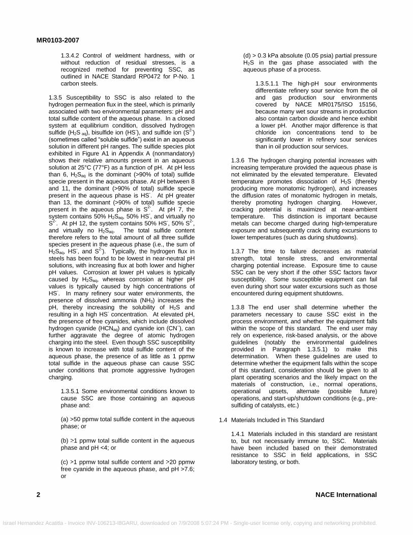
1.3.4.2 Control of weldment hardness, with or without reduction of residual stresses, is a recognized method for preventing SSC, as outlined in NACE Standard RP0472 for P-No. 1 carbon steels.
1.3.5 Susceptibility to SSC is also related to the hydrogen permeation flux in the steel, which is primarily associated with two environmental parameters: pH and total sulfide content of the aqueous phase. In a closed system at equilibrium condition, dissolved hydrogen sulfide (H2S aq), bisulfide ion (HS
-), and sulfide ion (S
2-)
(sometimes called ―soluble sulfide‖) exist in an aqueous solution in different pH ranges. The sulfide species plot exhibited in Figure A1 in Appendix A (nonmandatory) shows their relative amounts present in an aqueous solution at 25°C (77°F) as a function of pH. At pH less than 6, H2Saq is the dominant (>90% of total) sulfide specie present in the aqueous phase. At pH between 8 and 11, the dominant (>90% of total) sulfide specie present in the aqueous phase is HS
-. At pH greater
than 13, the dominant (>90% of total) sulfide specie present in the aqueous phase is S
2-. At pH 7, the
system contains 50% H2Saq, 50% HS-, and virtually no
S2-
. At pH 12, the system contains 50% HS-, 50% S
2-,
and virtually no H2Saq. The total sulfide content therefore refers to the total amount of all three sulfide species present in the aqueous phase (i.e., the sum of H2Saq, HS
-, and S
2-). Typically, the hydrogen flux in
steels has been found to be lowest in near-neutral pH solutions, with increasing flux at both lower and higher pH values. Corrosion at lower pH values is typically caused by H2Saq, whereas corrosion at higher pH values is typically caused by high concentrations of HS
-. In many refinery sour water environments, the
presence of dissolved ammonia (NH3) increases the pH, thereby increasing the solubility of H2S and resulting in a high HS
- concentration. At elevated pH,
the presence of free cyanides, which include dissolved hydrogen cyanide (HCNaq) and cyanide ion (CN
–), can
further aggravate the degree of atomic hydrogen charging into the steel. Even though SSC susceptibility is known to increase with total sulfide content of the aqueous phase, the presence of as little as 1 ppmw total sulfide in the aqueous phase can cause SSC under conditions that promote aggressive hydrogen charging.
1.3.5.1 Some environmental conditions known to cause SSC are those containing an aqueous phase and:
(a) >50 ppmw total sulfide content in the aqueous phase; or
(b) 1 ppmw total sulfide content in the aqueous phase and pH <4; or
(c) 1 ppmw total sulfide content and 20 ppmw free cyanide in the aqueous phase, and pH >7.6; or
2
ndez Acatitla - Invoice INV-106213-I8GARU, downloaded on 7/9/2008 5:07:
(d) > 0.3 kPa absolute (0.05 psia) partial pressure H2S in the gas phase associated with the aqueous phase of a process.
1.3.5.1.1 The high-pH sour environments differentiate refinery sour service from the oil and gas production sour environments covered by NACE MR0175/ISO 15156, because many wet sour streams in production also contain carbon dioxide and hence exhibit a lower pH. Another major difference is that chloride ion concentrations tend to be significantly lower in refinery sour services than in oil production sour services.
1.3.6 The hydrogen charging potential increases with increasing temperature provided the aqueous phase is not eliminated by the elevated temperature. Elevated temperature promotes dissociation of H2S (thereby producing more monatomic hydrogen), and increases the diffusion rates of monatomic hydrogen in metals, thereby promoting hydrogen charging. However, cracking potential is maximized at near-ambient temperature. This distinction is important because metals can become charged during high-temperature exposure and subsequently crack during excursions to lower temperatures (such as during shutdowns). 1.3.7 The time to failure decreases as material strength, total tensile stress, and environmental charging potential increase. Exposure time to cause SSC can be very short if the other SSC factors favor susceptibility. Some susceptible equipment can fail even during short sour water excursions such as those encountered during equipment shutdowns. 1.3.8 The end user shall determine whether the parameters necessary to cause SSC exist in the process environment, and whether the equipment falls within the scope of this standard. The end user may rely on experience, risk-based analysis, or the above guidelines (notably the environmental guidelines provided in Paragraph 1.3.5.1) to make this determination. When these guidelines are used to determine whether the equipment falls within the scope of this standard, consideration should be given to all plant operating scenarios and the likely impact on the materials of construction, i.e., normal operations, operational upsets, alternate (possible future) operations, and start-up/shutdown conditions (e.g., pre-sulfiding of catalysts, etc.)
1.4 Materials Included in This Standard
1.4.1 Materials included in this standard are resistant to, but not necessarily immune to, SSC. Materials have been included based on their demonstrated resistance to SSC in field applications, in SSC laboratory testing, or both.
NACE International
24 PM - Single-user license only, copying and networking prohibited.
MR0103-2007
Israel Her
1.4.2 Listed materials do not all exhibit the same level of resistance to SSC. Standard laboratory SSC tests, such as those addressed in NACE Standard TM0177,
7
are accelerated and severe tests. Materials that successfully pass these tests are generally more resistant to cracking in sour service than materials that fail the tests. Many alloys included in this standard perform satisfactorily in sour service even though they may crack in laboratory tests.
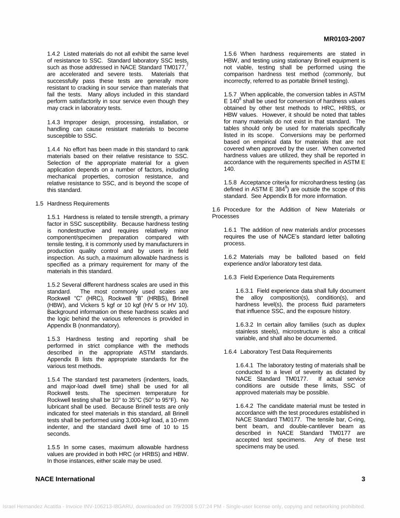
1.4.3 Improper design, processing, installation, or handling can cause resistant materials to become susceptible to SSC. 1.4.4 No effort has been made in this standard to rank materials based on their relative resistance to SSC. Selection of the appropriate material for a given application depends on a number of factors, including mechanical properties, corrosion resistance, and relative resistance to SSC, and is beyond the scope of this standard.
1.5 Hardness Requirements
1.5.1 Hardness is related to tensile strength, a primary factor in SSC susceptibility. Because hardness testing is nondestructive and requires relatively minor component/specimen preparation compared with tensile testing, it is commonly used by manufacturers in production quality control and by users in field inspection. As such, a maximum allowable hardness is specified as a primary requirement for many of the materials in this standard. 1.5.2 Several different hardness scales are used in this standard. The most commonly used scales are Rockwell ―C‖ (HRC), Rockwell ―B‖ (HRBS), Brinell (HBW), and Vickers 5 kgf or 10 kgf (HV 5 or HV 10). Background information on these hardness scales and the logic behind the various references is provided in Appendix B (nonmandatory). 1.5.3 Hardness testing and reporting shall be performed in strict compliance with the methods described in the appropriate ASTM standards. Appendix B lists the appropriate standards for the various test methods. 1.5.4 The standard test parameters (indenters, loads, and major-load dwell time) shall be used for all Rockwell tests. The specimen temperature for Rockwell testing shall be 10° to 35°C (50° to 95°F). No lubricant shall be used. Because Brinell tests are only indicated for steel materials in this standard, all Brinell tests shall be performed using 3,000-kgf load, a 10-mm indenter, and the standard dwell time of 10 to 15 seconds. 1.5.5 In some cases, maximum allowable hardness values are provided in both HRC (or HRBS) and HBW. In those instances, either scale may be used.
NACE International
nandez Acatitla - Invoice INV-106213-I8GARU, downloaded on 7/9/2008 5:07:
1.5.6 When hardness requirements are stated in HBW, and testing using stationary Brinell equipment is not viable, testing shall be performed using the comparison hardness test method (commonly, but incorrectly, referred to as portable Brinell testing). 1.5.7 When applicable, the conversion tables in ASTM E 140
8 shall be used for conversion of hardness values
obtained by other test methods to HRC, HRBS, or HBW values. However, it should be noted that tables for many materials do not exist in that standard. The tables should only be used for materials specifically listed in its scope. Conversions may be performed based on empirical data for materials that are not covered when approved by the user. When converted hardness values are utilized, they shall be reported in accordance with the requirements specified in ASTM E 140. 1.5.8 Acceptance criteria for microhardness testing (as defined in ASTM E 384
9) are outside the scope of this
standard. See Appendix B for more information.
1.6 Procedure for the Addition of New Materials or Processes
1.6.1 The addition of new materials and/or processes requires the use of NACE’s standard letter balloting process. 1.6.2 Materials may be balloted based on field experience and/or laboratory test data. 1.6.3 Field Experience Data Requirements
1.6.3.1 Field experience data shall fully document the alloy composition(s), condition(s), and hardness level(s), the process fluid parameters that influence SSC, and the exposure history. 1.6.3.2 In certain alloy families (such as duplex stainless steels), microstructure is also a critical variable, and shall also be documented.
1.6.4 Laboratory Test Data Requirements
1.6.4.1 The laboratory testing of materials shall be conducted to a level of severity as dictated by NACE Standard TM0177. If actual service conditions are outside these limits, SSC of approved materials may be possible. 1.6.4.2 The candidate material must be tested in accordance with the test procedures established in NACE Standard TM0177. The tensile bar, C-ring, bent beam, and double-cantilever beam as described in NACE Standard TM0177 are accepted test specimens. Any of these test specimens may be used.
3
24 PM - Single-user license only, copying and networking prohibited.
MR0103-2007
Israel Hernan
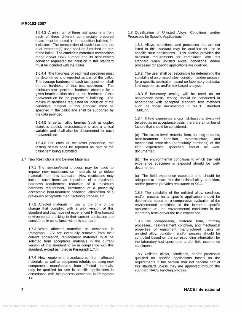
1.6.4.3 A minimum of three test specimens from each of three different commercially prepared heats must be tested in the condition balloted for inclusion. The composition of each heat and the heat treatment(s) used shall be furnished as part of the ballot. The candidate material’s composition range and/or UNS number and its heat-treated condition requested for inclusion in this standard must be included with the ballot. 1.6.4.4 The hardness of each test specimen must be determined and reported as part of the ballot. The average hardness of each test specimen shall be the hardness of that test specimen. The minimum test specimen hardness obtained for a given heat/condition shall be the hardness of that heat/condition for the purpose of balloting. The maximum hardness requested for inclusion of the candidate material in this standard must be specified in the ballot and shall be supported by the data provided. 1.6.4.5 In certain alloy families (such as duplex stainless steels), microstructure is also a critical variable, and shall also be documented for each heat/condition. 1.6.4.6 For each of the tests performed, the testing details shall be reported as part of the ballot item being submitted.
1.7 New Restrictions and Deleted Materials
1.7.1 The revision/ballot process may be used to impose new restrictions on materials or to delete materials from this standard. New restrictions may include such items as imposition of a maximum hardness requirement, reduction of a maximum hardness requirement, elimination of a previously acceptable heat-treatment condition, elimination of a previously acceptable manufacturing process, etc. 1.7.2 Affected materials in use at the time of the change that complied with a prior version of this standard and that have not experienced H2S-enhanced environmental cracking in their current application are considered in compliance with this standard. 1.7.3 When affected materials as described in Paragraph 1.7.2 are eventually removed from their current application, replacement materials must be selected from acceptable materials in the current version of this standard to be in compliance with this standard, except as noted in Paragraph 1.7.4. 1.7.4 New equipment manufactured from affected materials, as well as equipment refurbished using new components manufactured from affected materials, may be qualified for use in specific applications in accordance with the process described in Paragraph 1.8.
4
dez Acatitla - Invoice INV-106213-I8GARU, downloaded on 7/9/2008 5:07:
1.8 Qualification of Unlisted Alloys, Conditions, and/or Processes for Specific Applications
1.8.1 Alloys, conditions, and processes that are not listed in this standard may be qualified for use in specific sour applications. This section provides the minimum requirements for compliance with this standard when unlisted alloys, conditions, and/or processes for specific applications are qualified. 1.8.2 The user shall be responsible for determining the suitability of an unlisted alloy, condition, and/or process for a specific application based on laboratory test data, field experience, and/or risk-based analysis. 1.8.3 If laboratory testing will be used as an acceptance basis, testing should be conducted in accordance with accepted standard test methods such as those documented in NACE Standard TM0177. 1.8.4 If field experience and/or risk-based analysis will be used as an acceptance basis, there are a number of factors that should be considered: (a) The stress level, material form, forming process, heat-treatment condition, microstructure, and mechanical properties (particularly hardness) of the field experience specimen should be well-documented. (b) The environmental conditions to which the field experience specimen is exposed should be well-documented. (c) The field experience exposure time should be adequate to ensure that the unlisted alloy, condition, and/or process provides resistance to SSC.
1.8.5 The suitability of the unlisted alloy, condition, and/or process for a specific application should be determined based on a comparative evaluation of the environmental conditions in the intended specific application vs. the environmental conditions in the laboratory tests and/or the field experience. 1.8.6 The composition, material form, forming processes, heat-treatment condition, and mechanical properties of equipment manufactured using an unlisted alloy, condition, and/or process should be controlled based on the corresponding information for the laboratory test specimens and/or field experience specimens. 1.8.7 Unlisted alloys, conditions, and/or processes qualified for specific applications based on the requirements in this section shall not become part of this standard unless they are approved through the standard NACE balloting process.
NACE International
24 PM - Single-user license only, copying and networking prohibited.

MR0103-2007
Israel Herna
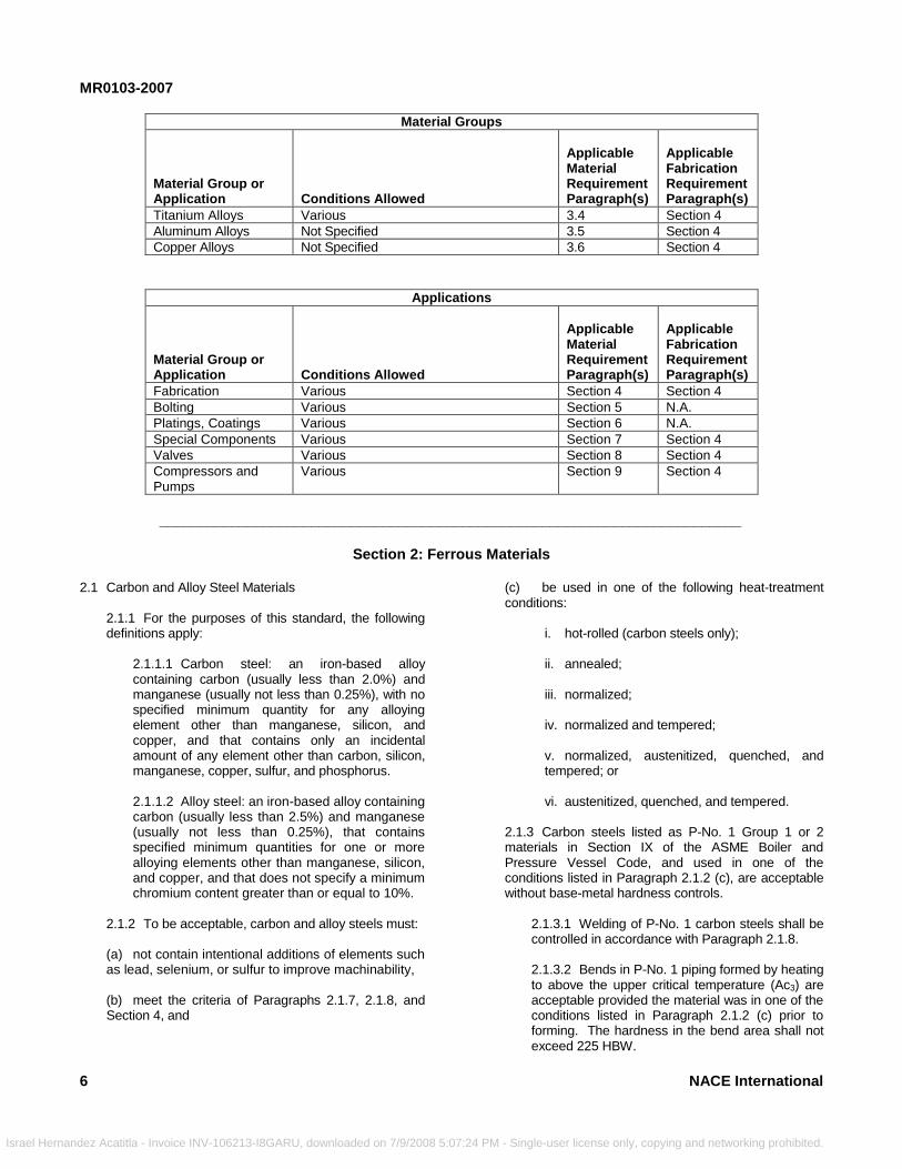
1.9 Standard Road Map 1.9.1 For ease of use, Table 1 provides general information by material/application group, as well as
NACE International
ndez Acatitla - Invoice INV-106213-I8GARU, downloaded on 7/9/2008 5:07:24
references to specific paragraphs that cover applicable material and fabrication requirements.
Table 1—“Road Map” for This Standard
Material Groups
Material Group or Application Conditions Allowed
Applicable Material Requirement Paragraph(s)
Applicable Fabrication Requirement Paragraph(s)
Carbon Steels
(a) Hot-rolled (b) Annealed (c) Normalized (d) Normalized and tempered (e) Normalized, austenitized, quenched, and tempered (f) Austenitized, quenched, and tempered.
2.1 2.1.8, Section 4
Alloy Steels (a) Annealed (b) Normalized (c) Normalized and tempered (d) Normalized, austenitized, quenched, and tempered (e) Austenitized, quenched, and tempered.
2.1 2.1.8, Section 4
Ferritic Ductile Iron Annealed 2.2.2 2.2.3
Ferritic Stainless Steels
Annealed 2.3 Section 4
Specific Martensitic Stainless Steels
(a) Normalized and double-tempered (b) Quenched and double-tempered
2.4 2.4.3, Section 4
Specific Low-Carbon Martensitic Stainless Steels
Quenched and double-tempered 2.4.2 2.4.3, Section 4
Austenitic Stainless Steels
Solution-annealed 2.5 Section 4
Specific Austenitic Stainless Steels
Solution-annealed or hot-rolled 2.6 Section 4
Highly Alloyed Austenitic Stainless Steels
Solution-annealed or solution-annealed and cold-worked
2.7 Section 4
Duplex Stainless Steels
Solution-annealed 2.8 2.8.2, Section 4
Precipitation-Hardenable Stainless Steels
Solution-annealed and precipitation- hardened
2.9 Section 4
Solid-Solution Nickel Alloys
Solution-annealed 3.1.1 Section 4
Precipitation-Hardenable Nickel Alloys
Various 3.1.2 Section 4
Cobalt-Nickel-Chromium-Molybdenum Alloys
Various 3.2 Section 4
Cobalt-Nickel-Chromium-Tungsten Alloys
Not specified 3.3 Section 4
5
PM - Single-user license only, copying and networking prohibited.
MR0103-2007
6
Israel Hernandez
Material Groups
Material Group or Application Conditions Allowed
Applicable Material Requirement Paragraph(s)
Applicable Fabrication Requirement Paragraph(s)
Titanium Alloys Various 3.4 Section 4
Aluminum Alloys Not Specified 3.5 Section 4
Copper Alloys Not Specified 3.6 Section 4
Applications
Material Group or Application Conditions Allowed
Applicable Material Requirement Paragraph(s)
Applicable Fabrication Requirement Paragraph(s)
Fabrication Various Section 4 Section 4
Bolting Various Section 5 N.A.
Platings, Coatings Various Section 6 N.A.
Special Components Various Section 7 Section 4
Valves Various Section 8 Section 4
Compressors and Pumps
Various Section 9 Section 4
_________________________________________________________________________
Acatitla - Invoice INV-106213-I8GARU, downlo
Section 2: Ferrous Materials
2.1 Carbon and Alloy Steel Materials2.1.1 For the purposes of this standard, the following definitions apply:
2.1.1.1 Carbon steel: an iron-based alloy containing carbon (usually less than 2.0%) and manganese (usually not less than 0.25%), with no specified minimum quantity for any alloying element other than manganese, silicon, and copper, and that contains only an incidental amount of any element other than carbon, silicon, manganese, copper, sulfur, and phosphorus. 2.1.1.2 Alloy steel: an iron-based alloy containing carbon (usually less than 2.5%) and manganese (usually not less than 0.25%), that contains specified minimum quantities for one or more alloying elements other than manganese, silicon, and copper, and that does not specify a minimum chromium content greater than or equal to 10%.
2.1.2 To be acceptable, carbon and alloy steels must: (a) not contain intentional additions of elements such as lead, selenium, or sulfur to improve machinability, (b) meet the criteria of Paragraphs 2.1.7, 2.1.8, and Section 4, and
aded on 7/9/2008 5:07:24
(c) be used in one of the following heat-treatment conditions:
i. hot-rolled (carbon steels only); ii. annealed; iii. normalized; iv. normalized and tempered; v. normalized, austenitized, quenched, and tempered; or vi. austenitized, quenched, and tempered.
2.1.3 Carbon steels listed as P-No. 1 Group 1 or 2 materials in Section IX of the ASME Boiler and Pressure Vessel Code, and used in one of the conditions listed in Paragraph 2.1.2 (c), are acceptable without base-metal hardness controls.
2.1.3.1 Welding of P-No. 1 carbon steels shall be controlled in accordance with Paragraph 2.1.8. 2.1.3.2 Bends in P-No. 1 piping formed by heating to above the upper critical temperature (Ac3) are acceptable provided the material was in one of the conditions listed in Paragraph 2.1.2 (c) prior to forming. The hardness in the bend area shall not exceed 225 HBW.
NACE International
PM - Single-user license only, copying and networking prohibited.
MR0103-2007
N
Israel Hernand
2.1.3.3 Weld repairs in P-No. 1 castings are subject to the welding requirements specified in Paragraph 2.1.8.3.
2.1.4 Other carbon steels shall have a maximum hardness of 22 HRC (237 HBW).
ACE International
ez Acatitla - Invoice INV-106213-I8GARU, downloaded on 7/9/2008 5:07:2
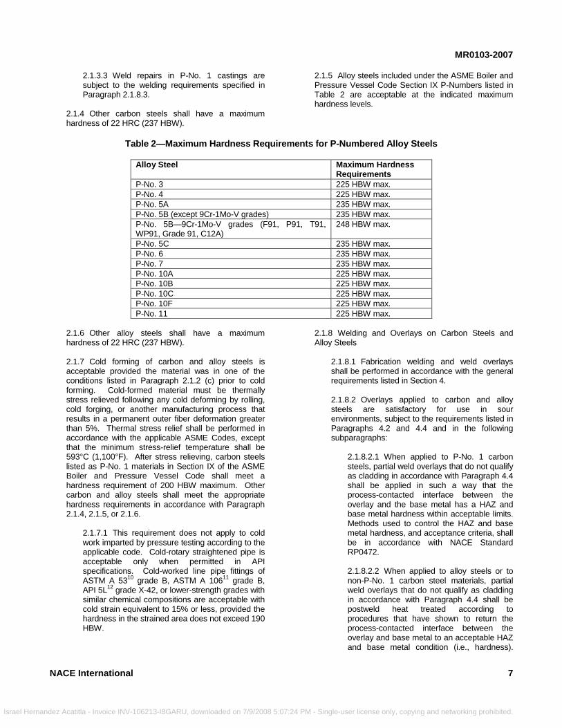
2.1.5 Alloy steels included under the ASME Boiler and Pressure Vessel Code Section IX P-Numbers listed in Table 2 are acceptable at the indicated maximum hardness levels.
Table 2—Maximum Hardness Requirements for P-Numbered Alloy Steels
Alloy Steel Maximum Hardness
Requirements
P-No. 3 225 HBW max.
P-No. 4 225 HBW max.
P-No. 5A 235 HBW max.
P-No. 5B (except 9Cr-1Mo-V grades) 235 HBW max.
P-No. 5B—9Cr-1Mo-V grades (F91, P91, T91, WP91, Grade 91, C12A)
248 HBW max.
P-No. 5C 235 HBW max.
P-No. 6 235 HBW max.
P-No. 7 235 HBW max.
P-No. 10A 225 HBW max.
P-No. 10B 225 HBW max.
P-No. 10C 225 HBW max.
P-No. 10F 225 HBW max.
P-No. 11 225 HBW max.
2.1.6 Other alloy steels shall have a maximum hardness of 22 HRC (237 HBW). 2.1.7 Cold forming of carbon and alloy steels is acceptable provided the material was in one of the conditions listed in Paragraph 2.1.2 (c) prior to cold forming. Cold-formed material must be thermally stress relieved following any cold deforming by rolling, cold forging, or another manufacturing process that results in a permanent outer fiber deformation greater than 5%. Thermal stress relief shall be performed in accordance with the applicable ASME Codes, except that the minimum stress-relief temperature shall be 593°C (1,100°F). After stress relieving, carbon steels listed as P-No. 1 materials in Section IX of the ASME Boiler and Pressure Vessel Code shall meet a hardness requirement of 200 HBW maximum. Other carbon and alloy steels shall meet the appropriate hardness requirements in accordance with Paragraph 2.1.4, 2.1.5, or 2.1.6.
2.1.7.1 This requirement does not apply to cold work imparted by pressure testing according to the applicable code. Cold-rotary straightened pipe is acceptable only when permitted in API specifications. Cold-worked line pipe fittings of ASTM A 53
10 grade B, ASTM A 106
11 grade B,
API 5L12
grade X-42, or lower-strength grades with similar chemical compositions are acceptable with cold strain equivalent to 15% or less, provided the hardness in the strained area does not exceed 190 HBW.
4
2.1.8 Welding and Overlays on Carbon Steels and Alloy Steels
2.1.8.1 Fabrication welding and weld overlays shall be performed in accordance with the general requirements listed in Section 4. 2.1.8.2 Overlays applied to carbon and alloy steels are satisfactory for use in sour environments, subject to the requirements listed in Paragraphs 4.2 and 4.4 and in the following subparagraphs:
2.1.8.2.1 When applied to P-No. 1 carbon steels, partial weld overlays that do not qualify as cladding in accordance with Paragraph 4.4 shall be applied in such a way that the process-contacted interface between the overlay and the base metal has a HAZ and base metal hardness within acceptable limits. Methods used to control the HAZ and base metal hardness, and acceptance criteria, shall be in accordance with NACE Standard RP0472. 2.1.8.2.2 When applied to alloy steels or to non-P-No. 1 carbon steel materials, partial weld overlays that do not qualify as cladding in accordance with Paragraph 4.4 shall be postweld heat treated according to procedures that have shown to return the process-contacted interface between the overlay and base metal to an acceptable HAZ and base metal condition (i.e., hardness).
7
PM - Single-user license only, copying and networking prohibited.
MR0103-2007
8
Israel Hernande
Hardness acceptance criteria shall be in accordance with limits provided in Paragraphs 2.1.3 through 2.1.6, and/or 2.1.8.4, as appropriate. 2.1.8.2.3 When thermal spray coatings are applied to P-No. 1 carbon steel materials in such a manner that any portion of the base metal exceeds the lower critical temperature (e.g., in the case of a spray and fuse coating), the procedures used shall ensure that the base metal has HAZ and base metal hardness within acceptable limits. Methods used to control the HAZ and base metal hardness, and acceptance criteria, shall be in accordance with NACE Standard RP0472. 2.1.8.2.4 When thermal spray coatings are applied to alloy steels or to non-P-No. 1 carbon steel materials in such a manner that any portion of the base metal exceeds the lower critical temperature (e.g., in the case of a spray and fuse coating), postweld heat treatment (PWHT) shall be performed according to procedures that have been shown to return the base metal to an acceptable HAZ and base metal condition (i.e., hardness). Hardness acceptance criteria shall be in accordance with limits provided in Paragraphs 2.1.3 through 2.1.6 and/or 2.1.8.4 as appropriate.
2.1.8.3 Weldments in carbon steels listed as P-No. 1 materials in Section IX of the ASME Boiler and Pressure Vessel Code shall be produced using one of the methods outlined in NACE Standard RP0472 to prevent excessive weldment hardness. 2.1.8.4 Weldments in alloy steels with assigned ASME Boiler and Pressure Vessel Code Section IX P-Numbers shall not exceed the hardness limits specified in Paragraph 2.1.5. The hardness of materials without assigned ASME Boiler and Pressure Vessel Code Section IX P-Numbers shall not exceed 237 HBW (22 HRC) maximum.
2.1.8.4.1 Some industry codes (such as ANSI/NB-23
13) allow welding of P-No. 3 and
P-No. 4 alloy steels without PWHT in certain circumstances. Non-PWHT procedures of this type may be utilized provided a hardness traverse has been performed on the procedure qualification record (PQR) specimen to demonstrate the ability of the procedure to produce weldments of acceptable hardness. The traverse shall encompass the base metal, HAZ, and filler metal at the top and bottom of the weldment, and should be conducted in accordance with Figure 2 or 3 (as applicable) in NACE
z Acatitla - Invoice INV-106213-I8GARU, downloaded on 7/9/2008 5:07
Standard RP0472. No individual reading shall exceed 248 HV 10. Other alloy steel materials shall always receive PWHT when this standard applies to ensure low hardness in the weld metal and HAZ. A hardness traverse, as described above, shall be performed on the PQR specimen to demonstrate the ability of the PWHT time and temperature to produce weldments of acceptable hardness.
2.2 Cast Iron and Ductile Iron Materials
2.2.1 Gray, austenitic, and white cast irons are not acceptable for use as pressure-containing members. These materials may be used in internal components related to API and other appropriate standards, provided their use has been approved by the purchaser. 2.2.2 Ferritic ductile iron in accordance with ASTM A 395
14 is acceptable for equipment when API, ANSI,
and/or other industry standards approve its use. 2.2.3 Welding is not permitted on gray cast iron or ductile iron components.
2.3 Ferritic Stainless Steel Materials
2.3.1 Ferritic stainless steels are acceptable at a 22 HRC maximum hardness provided they are in the annealed condition and meet the criteria of Section 4.
2.4 Martensitic Stainless Steel Materials
2.4.1 Martensitic stainless steels (UNS S41000, S42000, J91150 [CA15], and J91151 [CA15M]), either cast or wrought, are acceptable at 22 HRC maximum hardness provided they are heat treated in accordance with Paragraph 2.4.1.1 and meet the criteria of Section 4. Variations containing alloying elements such as lead, selenium, or sulfur to improve machinability are not acceptable. Martensitic stainless steels that are in accordance with this standard have provided satisfactory field service in some sour environments. These materials may, however, exhibit threshold stress levels in NACE Standard TM0177 laboratory tests that are lower than the levels for other materials included in this standard.
2.4.1.1 Heat-Treatment Procedure (Three-Step Process) for UNS S41000, S42000, J91150 (CA15), and J91151 (CA15M) Martensitic Stainless Steel
2.4.1.1.1 Austenitize and quench or air cool. 2.4.1.1.2 Temper at 621°C (1,150°F) minimum; then air cool to ambient temperature.
NACE International
:24 PM - Single-user license only, copying and networking prohibited.
MR0103-2007
Israel Hernand
2.4.1.1.3 Temper at 621°C (1,150°F) minimum, but lower than the first tempering temperature; then air cool to ambient temperature.
2.4.2 Low-carbon, 12Cr-4Ni-Mo martensitic stainless steels, either cast UNS J91540 (CA6NM) or wrought UNS S42400, are acceptable to 23 HRC
(8) maximum
provided they are heat treated in accordance with Paragraph 2.4.2.1. Variations containing alloying elements such as lead, selenium, or sulfur to improve machinability are not acceptable.
2.4.2.1 Heat-Treatment Procedure (Three-Step Process)
2.4.2.1.1 Austenitize at 1,010°C (1,850°F) minimum and air or oil quench to ambient temperature. 2.4.2.1.2 Temper at 649° to 691°C (1,200° to 1,275°F) and air cool to ambient temperature. 2.4.2.1.3 Temper at 593° to 621°C (1,100° to 1,150°F) and air cool to ambient temperature.
2.4.3 Welding and Overlays on Martensitic Stainless Steels
2.4.3.1 Weldments in martensitic stainless steels listed in Paragraph 2.4.1 shall undergo a PWHT at 621°C (1,150°F) minimum and shall produce weldment hardness of 22 HRC maximum. 2.4.3.2 Weldments in low-carbon martensitic stainless steels defined in Paragraph 2.4.2 shall undergo a double-cycle PWHT after first being cooled to ambient temperature. The double-cycle
NACE International
ez Acatitla - Invoice INV-106213-I8GARU, downloaded on 7/9/2008 5:07:24
PWHT shall consist of heating at 671° to 691°C (1,240° to 1,275°F), cooling to ambient temperature, followed by heating at 579° to 621°C (1,075° to 1,150°F). 2.4.3.3 Welding may only be performed on base materials listed in Paragraph 2.4.2 that have previously been austenitized, quenched, and double-tempered. Welding between martensitic stainless steels and other materials (including carbon steels, alloy steels, and austenitic stainless steels) is outside the scope of this standard. 2.4.3.4 Overlays applied to martensitic stainless steels by thermal processes such as welding, silver brazing, or thermal-spray systems are satisfactory for use in sour environments. In those cases in which the lower critical temperatures are exceeded, the component must be heat treated or thermally stress relieved according to procedures that have been shown to return the base metal to 22 HRC maximum.
2.5 Austenitic Stainless Steel Materials
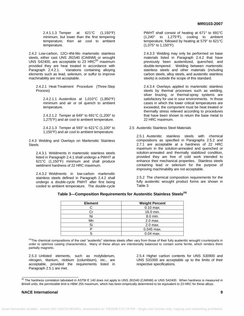
2.5.1 Austenitic stainless steels with chemical compositions as specified in Paragraphs 2.5.2 and 2.7.1 are acceptable at a hardness of 22 HRC maximum in the solution-annealed and quenched or solution-annealed and thermally stabilized condition, provided they are free of cold work intended to enhance their mechanical properties. Stainless steels containing lead or selenium for the purpose of improving machinability are not acceptable. 2.5.2 The chemical composition requirements for the fully austenitic wrought product forms are shown in Table 3:
Table 3—Composition Requirements for Austenitic Stainless Steels(A)
Element Weight Percent
C 0.10 max.
Cr 16.0 min.
Ni 8.0 min.
Mn 2.0 max.
Si 2.0 max.
P 0.045 max.
S 0.04 max.
(A)The chemical compositions of the cast ―austenitic‖ stainless steels often vary from those of their fully austenitic wrought counterparts in
order to optimize casting characteristics. Many of these alloys are intentionally balanced to contain some ferrite, which renders them partially magnetic.
2.5.3 Unlisted elements, such as molybdenum, nitrogen, titanium, niobium (columbium), etc., are acceptable, provided the requirements listed in Paragraph 2.5.1 are met.
P
2.5.4 Higher carbon contents for UNS S30900 and UNS S31000 are acceptable up to the limits of their respective specifications.
____________________________ (8)
The hardness correlation tabulated in ASTM E 140 does not apply to UNS J91540 (CA6NM) or UNS S42400. When hardness is measured in Brinell units, the permissible limit is HBW 255 maximum, which has been empirically determined to be equivalent to 23 HRC for these alloys.
9
M - Single-user license only, copying and networking prohibited.
MR0103-2007
2
Israel Herna
2.6 Specific Austenitic Stainless Steel Grades
2.6.1 Austenitic stainless steel UNS S20910 is acceptable in the solution-annealed, hot-rolled (hot/cold-worked), or cold-worked condition at 35 HRC maximum hardness.
2.7 Highly Alloyed Austenitic Stainless Steels
2.7.1 Highly alloyed austenitic stainless steels in the composition range specified in Paragraph 2.7.2 are acceptable at a 35 HRC maximum hardness in the solution-annealed condition or solution-annealed and cold-worked condition. Free-machining highly alloyed austenitic stainless steels are not acceptable. 2.7.2 The chemical composition requirements for the highly alloyed austenitic stainless steels are as follows:
%Ni + (2 x %Mo) >30 and Mo >2%
or
Pitting Resistance Equivalent Number (PREN) >40%
where PREN is determined as shown in Equation (1):
PREN = %Cr + 3.3 (%Mo + 0.5 × %W) + 16 × %N (1) Note: For the purposes of this standard, the PREN factor is used only to define a group of alloys from a compositional standpoint. Use of the PREN factor to predict relative corrosion resistance is outside the scope of this standard. 2.8 Duplex Stainless Steel Materials
2.8.1 Wrought and cast duplex stainless steel products are acceptable in the solution-annealed and liquid-quenched condition. Tubing shall be rapidly cooled by liquid quenching, or by air or inert gas cooling to below 315°C (600°F). The ferrite content shall be 35 to 65 vol%. Aging heat treatments to increase strength and/or hardness are prohibited due to the formation of embrittling phases.
2.8.1.1 The hardness of grades with PREN ≤ 40% according to Equation (1) shall be 28
(9) HRC
maximum. 2.8.1.2 The hardness of grades with PREN > 40% according to Equation (1) shall be 32 HRC
(9)
maximum.
10
ndez Acatitla - Invoice INV-106213-I8GARU, downloaded on 7/9/2008 5:07:24
2.8.2 Welding of Duplex Stainless Steels
2.8.2.1 Weld procedure qualifications/specifi-cations for duplex stainless steels shall include the following items: (a) The PQR shall include a hardness traverse conducted using the 10-kg Vickers (HV 10) scale. The traverse shall encompass the base metal, HAZ, and filler metal at the top and bottom of the weldment, and should be conducted in accordance with Figure 2 or 3 (as applicable) in NACE Standard RP0472. The average hardness shall not exceed 310 HV 10, and no individual reading shall exceed 320 HV 10. (b) The PQR shall include an analysis of the ferrite content of the weld deposit and HAZ. The analysis shall be conducted in accordance with ASTM E 562,
15 and the measured ferrite content
shall be 35 to 65 vol%. (c) The PQR shall list the heat input utilized during the qualification, as determined by Equation (2).
speed travel
60) x volts x (amps (2)
(d) The welding procedure specification (WPS) shall restrict the heat input during welding to the PQR heat input value ±10%. (e) The PQR shall list the wall thickness of the PQR specimen. (f) The WPS shall not allow welding of components with wall thicknesses that deviate by more than 20% from that of the PQR specimen.
.9 Precipitation-Hardenable Stainless Steel Materials
2.9.1 Austenitic precipitation-hardenable stainless steel with chemical composition in accordance with UNS S66286 is acceptable at 35 HRC maximum hardness provided it is in either the solution-annealed and aged or solution-annealed and double-aged condition. 2.9.2 UNS S17400 and UNS S15500 wrought martensitic precipitation-hardenable stainless steels are acceptable at 33 HRC maximum hardness in either the H1150D condition (heat treated in accordance with Paragraph 2.9.2.2) or H1150M condition (heat treated
____________________________ (9)
Brinell hardness measurements obtained on duplex stainless steels cannot be converted to Rockwell C using existing tables in ASTM E
140. Use of empirically derived tables for conversion is subject to the approval of the user.
NACE International
PM - Single-user license only, copying and networking prohibited.
MR0103-2007
N
Israel Hernand
in accordance with Paragraph 2.9.2.3). ASTM A 74716
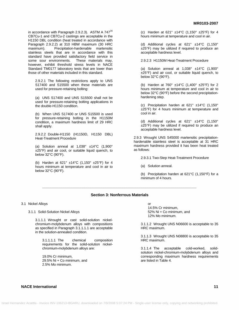
CB7Cu-1 and CB7Cu-2 castings are acceptable in the H1150 DBL condition (heat treated in accordance with Paragraph 2.9.2.2) at 310 HBW maximum (30 HRC maximum). Precipitation-hardenable martensitic stainless steels that are in accordance with this standard have provided satisfactory field service in some sour environments. These materials may, however, exhibit threshold stress levels in NACE Standard TM0177 laboratory tests that are lower than those of other materials included in this standard.
2.9.2.1 The following restrictions apply to UNS S17400 and S15500 when these materials are used for pressure-retaining bolting:
(a) UNS S17400 and UNS S15500 shall not be used for pressure-retaining bolting applications in the double-H1150 condition. (b) When UNS S17400 or UNS S15500 is used for pressure-retaining bolting in the H1150M condition, a maximum hardness limit of 29 HRC shall apply. 2.9.2.2 Double-H1150 (H1150D, H1150 DBL) Heat-Treatment Procedure (a) Solution anneal at 1,038° ±14°C (1,900° ±25°F) and air cool, or suitable liquid quench, to below 32°C (90°F). (b) Harden at 621° ±14°C (1,150° ±25°F) for 4 hours minimum at temperature and cool in air to below 32°C (90°F).
ACE International
__________________________________________
ez Acatitla - Invoice INV-106213-I8GARU, downloaded on 7/9/2008 5:07:24 P
(c) Harden at 621° ±14°C (1,150° ±25°F) for 4 hours minimum at temperature and cool in air. (d) Additional cycles at 621° ±14°C (1,150° ±25°F) may be utilized if required to produce an acceptable hardness level. 2.9.2.3 H1150M Heat-Treatment Procedure (a) Solution anneal at 1,038° ±14°C (1,900° ±25°F) and air cool, or suitable liquid quench, to below 32°C (90°F). (b) Harden at 760° ±14°C (1,400° ±25°F) for 2 hours minimum at temperature and cool in air to below 32°C (90°F) before the second precipitation-hardening step. (c) Precipitation harden at 621° ±14°C (1,150° ±25°F) for 4 hours minimum at temperature and cool in air. (d) Additional cycles at 621° ±14°C (1,150° ±25°F) may be utilized if required to produce an acceptable hardness level.
2.9.3 Wrought UNS S45000 martensitic precipitation-hardenable stainless steel is acceptable at 31 HRC maximum hardness provided it has been heat treated as follows:
2.9.3.1 Two-Step Heat-Treatment Procedure (a) Solution anneal.
(b) Precipitation harden at 621°C (1,150°F) for a minimum of 4 hours.
_______________________________
Section 3: Nonferrous Materials
3.1 Nickel Alloys3.1.1 Solid-Solution Nickel Alloys
3.1.1.1 Wrought or cast solid-solution nickel-chromium-molybdenum alloys with compositions as specified in Paragraph 3.1.1.1.1 are acceptable in the solution-annealed condition.
3.1.1.1.1 The chemical composition requirements for the solid-solution nickel-chromium-molybdenum alloys are: 19.0% Cr minimum, 29.5% Ni + Co minimum, and 2.5% Mo minimum.
M
or 14.5% Cr minimum, 52% Ni + Co minimum, and 12% Mo minimum.
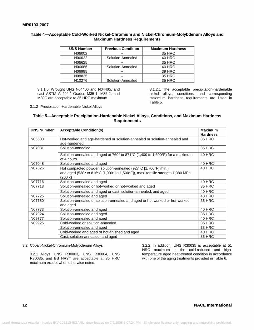
3.1.1.2 Wrought UNS N06600 is acceptable to 35 HRC maximum. 3.1.1.3 Wrought UNS N08800 is acceptable to 35 HRC maximum. 3.1.1.4 The acceptable cold-worked, solid-solution nickel-chromium-molybdenum alloys and corresponding maximum hardness requirements are listed in Table 4.
11
- Single-user license only, copying and networking prohibited.
MR0103-2007
1
Israel Hernande
Table 4—Acceptable Cold-Worked Nickel-Chromium and Nickel-Chromium-Molybdenum Alloys and Maximum Hardness Requirements
UNS Number Previous Condition Maximum Hardness
N06002 -- 35 HRC
N06022 Solution-Annealed 40 HRC
N06625 -- 35 HRC
N06686 Solution-Annealed 40 HRC
N06985 -- 39 HRC
N08825 -- 35 HRC
N10276 Solution-Annealed 35 HRC
2
z
3.1.1.5 Wrought UNS N04400 and N04405, and cast ASTM A 494
17 Grades M35-1, M35-2, and
M30C are acceptable to 35 HRC maximum.
3.1.2 Precipitation-Hardenable Nickel Alloys
Acatitla - Invoice INV-106213-I8GARU, downloaded on 7/9/2008 5:07:24 PM -
3.1.2.1 The acceptable precipitation-hardenable nickel alloys, conditions, and corresponding maximum hardness requirements are listed in Table 5.
Table 5—Acceptable Precipitation-Hardenable Nickel Alloys, Conditions, and Maximum Hardness
Requirements
UNS Number Acceptable Condition(s) Maximum Hardness
N05500 Hot-worked and age-hardened or solution-annealed or solution-annealed and age-hardened
35 HRC
N07031 Solution-annealed 35 HRC
Solution-annealed and aged at 760° to 871°C (1,400 to 1,600°F) for a maximum of 4 hours.
40 HRC
N07048 Solution-annealed and aged 40 HRC
N07626 Hot compacted powder, solution-annealed (927 C [1,700 F] min.)
and aged (538 to 816 C [1,000 to 1,500 F]), max. tensile strength 1,380 MPa (200 ksi)
40 HRC
N07716 Solution-annealed and aged 40 HRC
N07718 Solution-annealed or hot-worked or hot-worked and aged 35 HRC
Solution-annealed and aged or cast, solution-annealed, and aged 40 HRC
N07725 Solution-annealed and aged 43 HRC
N07750 Solution-annealed or solution-annealed and aged or hot worked or hot-worked and aged
35 HRC
N07773 Solution-annealed and aged 40 HRC
N07924 Solution-annealed and aged 35 HRC
N09777 Solution-annealed and aged 40 HRC
N09925 Cold-worked or solution-annealed 35 HRC
Solution-annealed and aged 38 HRC
Cold-worked and aged or hot-finished and aged 40 HRC
Cast, solution-annealed, and aged 35 HRC
3.2 Cobalt-Nickel-Chromium-Molybdenum Alloys
3.2.1 Alloys UNS R30003, UNS R30004, UNS R30035, and BS HR3
18 are acceptable at 35 HRC
maximum except when otherwise noted.
3.2.2 In addition, UNS R30035 is acceptable at 51 HRC maximum in the cold-reduced and high-temperature aged heat-treated condition in accordance with one of the aging treatments provided in Table 6.
NACE International
Single-user license only, copying and networking prohibited.

MR0103-2007
NACE International
_______________
Israel Hernandez Acatitla - Invoice INV-106213-I8GA
Table 6—UNS R30035 Heat Treatments
Minimum Time (hours)
Temperature
4 704°C (1,300°F)
4 732°C (1,350°F)
6 774°C (1,425°F)
4 788°C (1,450°F)
2 802°C (1,475°F)
1 816°C (1,500°F)
3.2.3 Wrought UNS R31233 is acceptable in the solution-annealed condition to 33 HRC maximum.
3.3 Cobalt-Nickel-Chromium-Tungsten Alloys
3.3.1 UNS R30605 is acceptable to 35 HRC maximum.
3.4 Titanium Alloys 3.4.1 Specific guidelines must be followed for successful applications of each titanium alloy specified in this standard. For example, hydrogen embrittlement
___________________________
RU, downloaded on 7/9/2008 5:07:24 P
of titanium alloys may occur if these alloys are galvanically coupled to certain active metals (e.g., carbon steel) in H2S-containing aqueous media at temperatures greater than 80°C (176°F). Hardness has not been shown to correlate with susceptibility to SSC, but has been included for alloys with high strength to indicate the maximum testing levels at which failure has not occurred. 3.4.2 The acceptable titanium alloys, conditions, and corresponding maximum hardness requirements are shown in Table 7.
Table 7—Acceptable Titanium Alloys, Conditions, and Maximum Hardness Requirements
UNS Number Condition Maximum Hardness
R50400 None specified 100 HRBS
R53400 Annealed at 774 14 C (1,425 25 F) for 2 hours, air cool 92 HRBS
R56260 Annealed or solution-annealed or solution-annealed and aged 45 HRC
R56323 Annealed 32 HRC
R56403 Annealed 36 HRC
R56404 Annealed 35 HRC
R58640 Annealed 42 HRC
3.5 Aluminum Alloys
3.5.1 Aluminum alloys are acceptable because they are not susceptible to SSC. However, they can suffer corrosion when exposed outside the pH range of about 4.0 to 8.5 and also pitting corrosion if chloride ions are present.
3.6 Copper Alloys
3.6.1 Copper alloys are acceptable because they are not susceptible to SSC. However, they can suffer corrosion because of the sulfides and also stress corrosion cracking if there is NH3 present, as often noted in sour refinery environments.
_______________________________
Section 4: General Fabrication Requirements
4.1 Materials and fabrication processes shall meet the requirements of this section. 4.2 Overlays4.2.1 Tungsten-carbide alloys and ceramics are acceptable as overlays. Following application of the overlay, the base material shall meet the base metal hardness as specified in the pertinent paragraph in Section 2 or 3.
4.2.2 Joining of dissimilar materials, such as cemented carbides to alloy steels by silver brazing, is acceptable. After brazing, the base material shall meet the hardness requirement for that base metal as listed in the pertinent paragraph in Section 2 or 3. 4.2.3 The base materials listed in Sections 2 and 3 are also acceptable as weld overlays, provided they meet the provisions of their respective paragraphs after being applied as overlays. Following application of the
13
M - Single-user license only, copying and networking prohibited.
MR0103-2007
Israel Hernand
overlay, the base material shall meet the hardness requirement for that base metal as listed in the pertinent paragraph in Section 2 or 3. 4.2.4 Overlays of cobalt-chromium-tungsten alloys, nickel-chromium-boron, and nickel-boron (as specified in AMS 4779
19) hardfacing alloys are acceptable.
Following application of the overlay, the base material shall meet the hardness requirement for that base metal as listed in the pertinent paragraph in Section 2 or 3.
4.3 Welding
4.3.1 All weldments shall meet the general requirements listed below. Specific welding requirements are provided for some materials in the pertinent material paragraphs, in which case those requirements shall also be met. In cases in which the specific welding requirements conflict with the requirements of this section, the specific material welding requirements shall override these general requirements. 4.3.2 Welders and welding procedures shall be qualified in accordance with AWS,
(10) API, ASME, or
other appropriate industry codes. 4.3.3 In similar-metal weldments, when the weld filler metal is similar to or equivalent to the base metal, the hardness requirement specified for the base metal shall be met in the HAZ and weld metal after welding and any applicable PWHT. 4.3.4 Dissimilar-metal welds, such as welds produced using filler metals that are more noble than the base metal, shall meet the following requirements:
4.3.4.1 The weld metal must be closely equivalent in chemistry and properties to a base material that is acceptable according to this standard. 4.3.4.2 The hardness limit for the deposited weld metal shall be the maximum hardness limit for the equivalent base metal in the solution-annealed condition. 4.3.4.3 The hardness requirement specified for the base metal shall be met in the HAZ after welding and any applicable PWHT.
14
ez Acatitla - Invoice INV-106213-I8GARU, downloaded on 7/9/2008 5:07
4.4 Cladding on Carbon Steels, Alloy Steels, and Martensitic Stainless Steels
4.4.1 For the purpose of this standard, cladding is defined as a metallurgically bonded layer of a corrosion-resistant alloy material applied to the entire wetted surface of a substrate material that is relatively less corrosion-resistant. 4.4.2 Acceptable fabrication methods used for cladding include hot rolling, explosion bonding, and weld overlaying. 4.4.3 Cladding materials shall be selected from Section 2 or 3 of this standard, and shall meet all requirements for that alloy as specified in the pertinent paragraph(s). 4.4.4 There are a number of factors that influence the SSC resistance of clad components, including, but not limited to: (a) Relative SSC resistance of the cladding material (b) Corrosion resistance of the clad layer in the process environment (which affects the rate of hydrogen production) (c) Hydrogen diffusion rate in the clad layer (d) Soundness of the clad layer (e) Relative SSC resistance of the substrate material (f) Fabrication methods used at junctions between neighboring clad components (g) Fabrication methods used at junctions between clad components and neighboring unclad components (h) Galvanic effects (if the substrate material becomes exposed or at junctions with neighboring unclad components) 4.4.5 Evaluation of these and other factors is outside the scope of this standard. Therefore, the end user shall specify whether or not the substrate material must meet the requirements of this standard.
4.5 Identification Stamping 4.5.1 Identification stamping using low-stress (dot, vibratory, and round V) stamps is acceptable.
____________________________ (10)
American Welding Society (AWS), 550 N.W. LeJeune Road, Miami, Florida 33126.
NACE International
:24 PM - Single-user license only, copying and networking prohibited.
MR0103-2007
Israel Herna
4.5.2 Conventional sharp V stamping is acceptable in low-stress areas, such as the outside diameter of flanges. Sharp V stamping is not permitted in high-stress areas unless the item receives a subsequent thermal treatment to reduce the hardness to below the maximum allowable hardness for the base material as specified in the applicable sections of this standard.
4.6 Threading
4.6.1 Machine-Cut Threads
4.6.1.1 Machine-cut threading processes are acceptable.
4.6.2 Cold-Formed (Rolled) Threads
4.6.2.1 After threads have been cold formed, the threaded component shall meet the heat-treatment
NACE International
______________________________________
ndez Acatitla - Invoice INV-106213-I8GARU, downloaded on 7/9/2008 5:07
conditions and hardness requirements given in either Section 3 or 4 for the parent alloy from which the threaded component was fabricated.
4.7 Cold-Deformation Processes
4.7.1 Cold-deformation processes such as burnishing that do not impart cold work exceeding that incidental to normal machining operations (such as turning or boring, rolling, threading, and drilling) are acceptable. 4.7.2 Cold deformation by controlled shot peening is permitted when applied to base materials that meet the requirements of this standard, and when limited to the use of a maximum shot size of 2.0 mm (0.080 in.) and a maximum of 10C Almen intensity. The process shall be controlled in accordance with AMS S 13165.
20
___________________________________
Section 5: Bolting
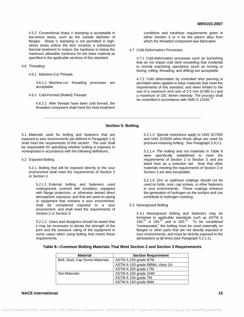
5.1 Materials used for bolting and fasteners that are exposed to sour environments (as defined in Paragraph 1.3) shall meet the requirements of this section. The user shall be responsible for specifying whether bolting is exposed or nonexposed in accordance with the following definitions. 5.2 Exposed Bolting5.2.1 Bolting that will be exposed directly to the sour environment shall meet the requirements of Section 2 or Section 3.
5.2.1.1 External bolting and fasteners used underground, covered with insulation, equipped with flange protectors, or otherwise denied direct atmospheric exposure, and that are used on piping or equipment that contains a sour environment, shall be considered exposed to a sour environment, and shall meet the requirements of Section 2 or Section 3. 5.2.1.2 Users and designers should be aware that it may be necessary to derate the strength of the joint and the pressure rating of the equipment in some cases when using bolting that meets these requirements.
:24
5.2.1.3 Special restrictions apply to UNS S17400 and UNS S15500 when these alloys are used for pressure-retaining bolting. See Paragraph 2.9.2.1. 5.2.1.4 The bolting and nut materials in Table 8 were specifically established to meet the requirements of Section 2 or Section 3, and are listed here as a selection aid. Note that other materials meeting the requirements of Section 2 or Section 3 are also acceptable. 5.2.1.5 Zinc or cadmium coatings should not be used on bolts, nuts, cap screws, or other fasteners in sour environments. These coatings enhance the generation of hydrogen on the surface and can contribute to hydrogen cracking.
5.3 Nonexposed Bolting
5.3.1 Nonexposed bolting and fasteners may be furnished to applicable standards such as ASTM A 193,
21 A 194,
22 and A 320.
23 To be considered
―nonexposed,‖ the bolting must be used externally on flanges or other parts that are not directly exposed to sour environments, and must be directly exposed to the atmosphere at all times (see Paragraph 5.2.1.1).
Table 8—Common Bolting Materials That Meet Section 2 and Section 3 Requirements
Material Section Requirement
Bolt, Stud, Cap Screw Materials ASTM A 193 grade B7M
ASTM A 193 grade B8MA, class 1A
ASTM A 320 grade L7M
Nut Materials ASTM A 194 grade 2HM
ASTM A 194 grade 7M
ASTM A 194 grade 8MA
15
PM - Single-user license only, copying and networking prohibited.
MR0103-2007
16
_________________________________________________________________________
_____________
Israel Hernandez Acatitla - Invoice INV-106213-I8
Section 6: Plating, Coatings, and Diffusion Processes
6.1 Metallic coatings (electroplated or electroless), conversion coatings, and plastic coatings or linings are not acceptable for preventing SSC of base metals. The use of such coatings for any other purpose (such as wear resistance or corrosion resistance) is outside the scope of this standard.
________________________
GARU, downloaded on 7/9/2008 5:0
6.2 Nitriding is an acceptable surface diffusion treatment when conducted at a temperature below the lower critical temperature of the material being treated. Its use as a means of preventing SSC is not acceptable.
____________________________________
Section 7: Special Components
7.1 Materials for special components including instrumentation, control devices, seals, bearings, and springs shall meet the requirements of this section if they are directly exposed to sour environments during normal operation of the device. Paragraph 1.2 provides guidelines to determine the applicability of the standard to specific uses. 7.2 Bearings7.2.1 Bearings directly exposed to sour environments shall be made from materials in Section 2 or Section 3, except as noted in Paragraph 7.2.2. Bearings made from other materials must be isolated from the sour environment to function properly. 7.2.2 Nickel-chromium-molybdenum-tungsten alloy UNS N10276 bearing pins, e.g., core roll pins, are acceptable in the cold-worked condition to 45 HRC maximum.
7.3 Springs 7.3.1 Springs directly exposed to the sour environment shall be made from materials described in Section 2 or Section 3 except as noted in Paragraphs 7.3.2, 7.3.3, and 7.3.4. 7.3.2 Cobalt-nickel-chromium-molybdenum alloy UNS R30003 is acceptable for springs in the cold-worked and age-hardened condition to 60 HRC maximum. UNS R30035 is acceptable for springs in the cold-worked and age-hardened condition to 55 HRC maximum when aged for a minimum of 4 hours at a temperature no lower than 649°C (1,200°F). 7.3.3 Nickel-chromium alloy UNS N07750 springs are acceptable in the cold-worked and age-hardened condition to 50 HRC maximum. 7.3.4 UNS N07090 is acceptable for springs for compressor valves in the cold-worked and age-hardened condition to 50 HRC maximum.
7
7.4 Instrumentation and Control Devices 7.4.1 Instrumentation and control device components directly exposed to sour environments shall be made from materials in Section 2 or Section 3.
7.4.1.1 UNS S31600 austenitic stainless steel, highly alloyed austenitic stainless steel (defined in Paragraph 2.7), or nickel alloy (defined in Paragraph 3.1) compression fittings, screen devices, and instrument or control tubing are acceptable even though these components may not satisfy the requirements stated for those materials in Section 2 or Section 3.
7.4.2 Diaphragms, Pressure-Measuring Devices, and Pressure Seals
7.4.2.1 Diaphragms, pressure-measuring devices, and pressure seals directly exposed to a sour environment shall be made from materials in Section 2 or Section 3, except as noted in Paragraphs 7.4.2.2, 7.4.2.3, and 7.4.2.4. 7.4.2.2 Cobalt-nickel-chromium-molybdenum alloys UNS R30003 and UNS R30004 are acceptable for diaphragms, pressure-measuring devices, and pressure seals to 60 HRC maximum.
7.4.2.3 Cobalt-nickel-chromium-molybdenum-tungsten alloy UNS R30260 diaphragms, pressure-measuring devices, and pressure seals are acceptable to 52 HRC maximum. 7.4.2.4 Pressure seals shall comply with the requirements of Section 2 or Section 3 or may be manufactured of wrought cobalt-chromium-nickel-molybdenum alloy UNS R30159 to 53 HRC maximum with the primary load-bearing or pressure-containing direction parallel to the longitudinal or rolling direction of wrought product.
7.4.3 Wrought UNS N08904 is acceptable for use as instrument tubing in the annealed condition to 180 HV 10 maximum.
NACE International
:24 PM - Single-user license only, copying and networking prohibited.
MR0103-2007
Israel Herna
7.5 Seal Rings and Gaskets 7.5.1 Seal rings directly exposed to a sour environment shall be made from materials in Section 2 or Section 3. 7.5.2 Austenitic stainless steel API compression seal rings and gaskets made of wrought or centrifugally cast ASTM A 351
24 grade CF8 or CF8M chemical
compositions are acceptable in the as-cast or solution-annealed condition to 160 HBW (83 HRBS) maximum.
7.6 Snap Rings
7.6.1 Snap rings directly exposed to a sour environment shall be made from applicable materials in Section 2 or Section 3, except as noted in Paragraph 7.6.2. 7.6.2 Precipitation-hardenable stainless steel alloy UNS S15700 snap rings originally in the RH950 solution-annealed and aged condition are acceptable when further heat treated to a hardness of 30 to 32
NACE International
HRC as follows:
________________________________________
________________________________________
ndez Acatitla - Invoice INV-106213-I8GARU, downloaded on 7/9/2008 5:07:24
7.6.2.1 Heat-treatment procedure (three-step process) shall be: (a) Temper at 621°C (1,150°F) for 4 hours, 15 minutes. Cool to room temperature in still air. (b) Temper at 621°C (1,150°F) for 4 hours, 15 minutes. Cool to room temperature in still air. (c) Temper at 566°C (1,050°F) for 4 hours, 15 minutes. Cool to room temperature in still air.
7.7 Special Process Parts
7.7.1 Cobalt-chromium-tungsten and nickel-chromium-boron alloys, whether cast, powder-metallurgy processed, or thermomechanically processed, are acceptable. 7.7.2 Tungsten-carbide alloys, whether cast or cemented, are acceptable.
_________________________________
Section 8: Valves
8.1 Valves shall meet the requirements of this section if they are to be exposed to sour environments (defined in Paragraph 1.3). A common failure mode of gate valves exposed to sour environments and not fabricated with hardness-controlled components is a dropped gate, rendering the valve inoperable.8.2 Valves (new or reconditioned), including internal components, shall be manufactured or remanufactured from materials in accordance with Section 2 or Section 3.
_________________________________
Section 9: Compressors and Pumps
9.1 Compressor and pump components that are to be exposed to sour environments (defined in Paragraph 1.3) shall be manufactured from materials in accordance with Section 2 or Section 3, except as noted in Paragraphs 9.2 and 9.3. 9.2 ASTM A 27825 Class 35 or 40 gray cast iron and ASTM
A 395 ductile iron are acceptable as compressor cylinders, liners, pistons, and valves. Aluminum alloy ASTM B 26
26
A03550-T7 is acceptable for pistons. Aluminum, soft carbon steel, and soft, low-carbon iron are acceptable as gaskets in compressors handling sour gas. 9.3 UNS G43200 and a modified version of UNS G43200 that contains 0.28 to 0.33% carbon are acceptable for compressor impellers at a maximum yield strength of 620
MPa (90 ksi) provided they have been heat treated in accordance with Paragraph 9.3.1.
9.3.1 Heat-Treatment Procedure (Three-Step Process)
9.3.1.1 Austenitize and quench 9.3.1.2 Temper at 621°C (1,150°F) minimum, but below the lower critical temperature. Cool to ambient temperature before the second temper. 9.3.1.3 Temper at 621°C (1,150°F) minimum, but lower than the first tempering temperature. Cool to ambient temperature.
17
PM - Single-user license only, copying and networking prohibited.
MR0103-2007
18
_________________________________________________________________________
Israel Hernandez Acatitla - Invoice INV-106213-I8GARU, downloaded on 7/9/2
References
1. NACE MR0175/ISO 15156 (latest revision), ―Petroleum and natural gas industries—Materials for use in H2S-containing Environments in oil and gas production‖ (Houston, TX: NACE). 2. NACE Standard RP0296 (latest revision), ―Guidelines for Detection, Repair, and Mitigation of Cracking of Existing Petroleum Refinery Pressure Vessels in Wet H2S Environments‖ (Houston, TX: NACE). 3. NACE Publication 8X194 (latest revision), ―Materials and Fabrication Practices for New Pressure Vessels Used in Wet H2S Refinery Service‖ (Houston, TX: NACE). 4. NACE Publication 8X294 (latest revision), ―Review of Published Literature on Wet H2S Cracking of Steels Through 1989‖ (Houston, TX: NACE). 5. ASME Boiler and Pressure Vessel Code, Section IX, Division I (latest revision), ―Welding and Brazing Qualifications‖ (New York, NY: ASME). 6. NACE Standard RP0472 (latest revision), ―Methods and Controls to Prevent In-Service Environmental Cracking of Carbon Steel Weldments in Corrosive Petroleum Refining Environments‖ (Houston, TX: NACE). 7. NACE Standard TM0177 (latest revision), ―Laboratory Testing of Metals for Resistance to Sulfide Stress Cracking and Stress Corrosion Cracking in H2S Environments‖ (Houston, TX: NACE). 8. ASTM E 140 (latest revision), ―Standard Hardness Conversion Tables for Metals—Relationship Among Brinell Hardness, Vickers Hardness, Rockwell Hardness, Superficial Hardness, Knoop Hardness, and Scleroscope Hardness‖ (West Conshohocken, PA: ASTM). 9. ASTM E 384 (latest revision), ―Standard Test Method for Microindentation Hardness of Materials‖ (West Conshohocken, PA: ASTM). 10. ASTM A 53/A 53M (latest revision), ―Standard Specification for Pipe, Steel, Black and Hot-Dipped, Zinc-Coated, Welded and Seamless‖ (West Conshohocken, PA: ASTM). 11. ASTM A 106 (latest revision), ―Standard Specification for Seamless Carbon Steel Pipe for High-Temperature Service‖ (West Conshohocken, PA: ASTM). 12. API 5L (latest revision), ―Specification for Line Pipe‖ (Washington, DC: API). 13. ANSI/NB-23, ―National Board Inspection Code‖ (Columbus, Ohio: The National Board of Boiler and Pressure Vessel Inspectors).008 5:0
14. A 395/A 395M (latest revision), ―Standard Specification for Ferritic Ductile Iron Pressure-Retaining Castings for Use at Elevated Temperatures‖ (West Conshohocken, PA: ASTM).
15. ASTM E 562 (latest revision), ―Standard Test Method for Determining Volume Fraction by Systematic Manual Point Count‖ (West Conshohocken, PA: ASTM).
16. ASTM A 747/A 747M (latest revision), ―Standard Specification for Steel Castings, Stainless, Precipitation Hardening‖ (West Conshohocken, PA: ASTM). 17. ASTM A 494/A 494M (latest revision), ―Standard Specifications for Castings, Nickel and Nickel Alloy‖ (West Conshohocken, PA: ASTM). 18. BS HR3 (latest revision), ―Specification for Nickel-Cobalt-Chromium-Molybdenum-Aluminium-Titanium Heat Resisting Alloy Billets, Bars, Forgings, and Parts (Nickel Base, Co 20, Cr 14.8, Mo 5, Al 4.7, Ti 1.2)‖ (London, U.K: BSI). 19. AMS 4779 (latest revision), ―Nickel Alloy, Brazing Filler Metal 94Ni - 3.5Si - 1.8B 1,800° to 1,950° F (982° to 1,066° C) Solidus-Liquidus Range (UNS N99640)‖ (Warrendale, PA: SAE). 20. SAE AMS S 13165 (latest revision), ―Shot Peening of Metal Parts‖ (Warrendale, PA: SAE). 21. ASTM A 193/A 193M (latest revision), ―Standard Specification for Alloy-Steel and Stainless Steel Bolting Materials for High-Temperature Service‖ (West Conshohocken, PA: ASTM). 22. ASTM A 194/A 194M (latest revision), ―Standard Specification for Carbon and Alloy Steel Nuts for Bolts for High Pressure and High Temperature Service, or Both‖ (West Conshohocken, PA: ASTM). 23. ASTM A 320/A 320M (latest revision), ―Standard Specification for Alloy Steel Bolting Materials for Low-Temperature Service‖ (West Conshohocken, PA: ASTM). 24. ASTM A 351/A 351 M (latest revision), ―Standard Specification for Casting, Austenitic, Austenitic-Ferritic (Duplex), for Pressure-Containing Parts‖ (West Conshohocken, PA: ASTM). 25. ASTM A 278/A 278M (latest revision), ―Standard Specification for Gray Iron Castings for Pressure-Containing Parts for Temperatures Up to 650°F‖ (West Conshohocken, PA: ASTM).
NACE International
7:24 PM - Single-user license only, copying and networking prohibited.
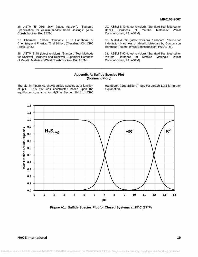
MR0103-2007
Israel Hern
26. ASTM B 26/B 26M (latest revision), ―Standard Specification for Aluminum-Alloy Sand Castings‖ (West Conshohocken, PA: ASTM). 27. Chemical Rubber Company. CRC Handbook of Chemistry and Physics, 72nd Edition, (Cleveland, OH: CRC Press, 1986). 28. ASTM E 18 (latest revision), ―Standard Test Methods for Rockwell Hardness and Rockwell Superficial Hardness of Metallic Materials‖ (West Conshohocken, PA: ASTM).
NACE International
_____________________________________
Figure A1: Sulfid
andez Acatitla - Invoice INV-106213-I8GARU, downloaded on 7/9/2008 5:0
29. ASTM E 10 (latest revision), ―Standard Test Method for Brinell Hardness of Metallic Materials‖ (West Conshohocken, PA: ASTM). 30. ASTM A 833 (latest revision), ―Standard Practice for Indentation Hardness of Metallic Materials by Comparison Hardness Testers‖ (West Conshohocken, PA: ASTM). 31. ASTM E 92 (latest revision), ―Standard Test Method for Vickers Hardness of Metallic Materials‖ (West Conshohocken, PA: ASTM).
____________________________________
Appendix A: Sulfide Species Plot (Nonmandatory)
The plot in Figure A1 shows sulfide species as a function of pH. This plot was constructed based upon the equilibrium constants for H2S in Section 8-41 of CRC
e
7
Handbook, 72nd Edition.27
See Paragraph 1.3.5 for further explanation.
Species Plot
For closed system at 25°C (77°F)0.0
0.1
0.2
0.3
0.4
0.5
0.6
0.7
0.8
0.9
1.0
1.1
1.2
0 1 2 3 4 5 6 7 8 9 10 11 12 13 14
pH
Mo
le F
rac
tio
n o
f S
ulf
ur
Sp
ec
ies
H2S(aq) HS-
S2-
Figure A1: Sulfide Species Plot for Closed Systems at 25°C (77°F)
19
:24 PM - Single-user license only, copying and networking prohibited.
MR0103-2007
20
_________________________________________________________________________
Israel Hernandez Acatitla - Invoic
Appendix B: Background Information on Hardness Testing and Requirements (Nonmandatory)
1. Accurate hardness testing requires strict compliance with the methods described in the appropriate ASTM standards. 2. Rockwell tests, performed in accordance with ASTM Standard E 18,28 are relatively quick, direct-reading tests,
and as such they are commonly used in manufacturing environments. These tests utilize loads ranging from 15 kgf to 150 kgf. Because of the relatively low loads that are utilized, the hardness indentations are small, and the measurements represent the hardness in a very localized volume of material. Therefore, these methods are very sensitive, and are suited for identifying localized hard spots. Drawbacks to this method are the size restrictions on components that can be tested, geometrical limitations that prevent testing in certain locations, and lack of portability. Note: Beginning in the 2002 revision of ASTM E 18, tungsten carbide balls are allowed for ―B‖ scale tests in addition to the hardened steel balls that were previously required. The scale designations for Rockwell ―B‖ hardness measurements are now ―HRBS‖ for tests run with a steel ball, and ―HRBW‖ for tests run with a tungsten carbide ball. The values required in this standard are all ―HRBS‖ values, because all testing in the past utilized the steel ball indenter. HRBS and HRBW test results differ due to the different mechanical properties of the two ball indenters. There are currently no standardized conversion tables available for conversion of HRBS to HRBW. 3. The Brinell method, performed in accordance with ASTM Standard E 10,
29 involves creation of an indentation,
optical measurement of the indentation diameter, and calculation of the hardness value. Because of the relatively large test loads utilized, this method produces a hardness value that represents an ―average‖ of the material hardness over a fairly large volume of material. Brinell testing is often used to measure the hardness of castings and forgings. Drawbacks to this method are the size restrictions on components that can be tested, geometrical limitations that prevent testing in certain locations, and lack of portability. Note that ASTM E 10 now requires Brinell testing to be performed with a tungsten carbide ball indenter. The symbol ―HBW‖ denotes testing performed in this manner. 4. Comparison hardness testers (commonly, but incorrectly, referred to as portable Brinell testers) utilize a hammer blow to simultaneously indent the component being evaluated and a test bar of known hardness. The relative indentation sizes are measured and a calculation is performed to determine the hardness of the component. Comparison testers are commonly utilized to check field weldments. This test method is performed in accordance with ASTM Standard A 833.
30 The hardness values
obtained using this method correlate directly to Brinell
e INV-106213-I8GARU, downloaded on 7/9/2008 5:0
values obtained using testing parameters defined in Paragraph 3 above. 5. The macro Vickers method, performed in accordance with ASTM E 92,
31 is similar to the Brinell method except it
makes use of a diamond pyramid indenter. The advantage of the Vickers method is that it provides relatively load-independent hardness values when performed with loads ranging from 25 gf to 120 kgf. It is common practice to use 5-kgf or 10-kgf Vickers hardness testing for welding procedure qualifications because this produces an accurate assessment of the weldment HAZ hardness. Vickers hardness criteria have been specified for a few selected welding procedure qualifications in this standard, based on proven field experience. Further details are available in NACE Standard RP0472. Vickers hardness is abbreviated HV, with the test load in kg indicated by a suffix number (example, 248 HV 10 denotes a Vickers hardness of 248 determined using a 10-kgf load). 6. Hardness requirements specified in this standard in HBW units are generally lower than the equivalent ―acceptable‖ HRC values (which applies to both conventional Brinell testing and comparison hardness testing) to compensate for nonhomogeneity of some material forms and weld deposits and/or to account for normal variations in field and/or production hardness testing using the comparison hardness tester. 7. HRC and HRBS are cited for particular materials or product forms under the following conditions: (a) When the raw material specification lists a hardness requirement in HRC or HRBS, (b) When the industry standard testing method for that product form is HRC or HRBS, or
(c) When the material will be tested at the component level. 8. HBW is cited for particular materials or product forms under the following conditions: (a) When the raw material specification lists a hardness requirement in HBW, (b) When the industry standard testing method for that product form is HBW, or (c) When the hardness requirement pertains to evaluation of weld metal hardness, which is most commonly performed using a portable Brinell hardness tester. 9. Microhardness evaluation, performed in accordance with ASTM E 384 using either the Vickers or Knoop method,
NACE International
7:24 PM - Single-user license only, copying and networking prohibited.
MR0103-2007
Israel Herna
may be necessary for some components that are too small to be tested by conventional methods. Microhardness testing utilizes loads of 1 kgf and lower. It should be noted that microhardness testing is more sensitive than the macro testing methods due to the very small indentation size. Because of this sensitivity, microscopic constituents such as
NACE International
ndez Acatitla - Invoice INV-106213-I8GARU, downloaded on 7/9/2008 5:07:
second phases can cause individual readings that are much higher than the bulk hardness. Thus, it is more difficult to establish general acceptance criteria based on microhardness testing. Individualized microhardness test procedures and associated acceptance criteria may need to be developed for each material/component combination being evaluated.
21
24 PM - Single-user license only, copying and networking prohibited.