nace-rp 0169-2002 control of external corrosion on underground or submerged metallic piping systems
TRANSCRIPT

StandardRecommended Practice
Control of External Corrosion on Underground orSubmerged Metallic Piping Systems
This NACE International standard represents a consensus of those individual members who havereviewed this document, its scope, and provisions. Its acceptance does not in any respectpreclude anyone, whether he has adopted the standard or not, from manufacturing, marketing,purchasing, or using products, processes, or procedures not in conformance with this standard.Nothing contained in this NACE International standard is to be construed as granting any right, byimplication or otherwise, to manufacture, sell, or use in connection with any method, apparatus, orproduct covered by Letters Patent, or as indemnifying or protecting anyone against liability forinfringement of Letters Patent. This standard represents minimum requirements and should in noway be interpreted as a restriction on the use of better procedures or materials. Neither is thisstandard intended to apply in all cases relating to the subject. Unpredictable circumstances maynegate the usefulness of this standard in specific instances. NACE International assumes noresponsibility for the interpretation or use of this standard by other parties and acceptsresponsibility for only those official NACE International interpretations issued by NACEInternational in accordance with its governing procedures and policies which preclude theissuance of interpretations by individual volunteers.
Users of this NACE International standard are responsible for reviewing appropriate health, safety,environmental, and regulatory documents and for determining their applicability in relation to thisstandard prior to its use. This NACE International standard may not necessarily address allpotential health and safety problems or environmental hazards associated with the use ofmaterials, equipment, and/or operations detailed or referred to within this standard. Users of thisNACE International standard are also responsible for establishing appropriate health, safety, andenvironmental protection practices, in consultation with appropriate regulatory authorities ifnecessary, to achieve compliance with any existing applicable regulatory requirements prior to theuse of this standard.
CAUTIONARY NOTICE: NACE International standards are subject to periodic review, and may berevised or withdrawn at any time without prior notice. NACE International requires that action betaken to reaffirm, revise, or withdraw this standard no later than five years from the date of initialpublication. The user is cautioned to obtain the latest edition. Purchasers of NACE Internationalstandards may receive current information on all standards and other NACE Internationalpublications by contacting the NACE International Membership Services Department, 1440 SouthCreek Drive, Houston, Texas 77084-4906 (telephone +1 [281] 228-6200).
Reaffirmed 2002-04-11Revised 1972, 1976, 1983, 1992
Approved 1969NACE International
1440 South Creek Dr.Houston, Texas 77084-4906
+1 (281)228-6200
ISBN 1-57590-035-1©2002, NACE International
NACE Standard RP0169-2002Item No. 21001

RP0169-2002
________________________________________________________________________
Foreword
This standard recommended practice presents procedures and practices for achieving effectivecontrol of external corrosion on buried or submerged metallic piping systems. Theserecommendations are also applicable to many other buried or submerged metallic structures. It isintended for use by corrosion control personnel concerned with the corrosion of buried orsubmerged piping systems, including oil, gas, water, and similar structures. This standarddescribes the use of electrically insulating coatings, electrical isolation, and cathodic protection asexternal corrosion control methods. It contains specific provisions for the application of cathodicprotection to existing bare, existing coated, and new piping systems. Also included are proceduresfor control of interference currents on pipelines.
This standard should be used in conjunction with the practices described in the following NACEstandards and publications when appropriate (use latest revisions):
RP05721
RP01772
RP02853
RP01864
RP02865
RP03876
RP01887
TPC 118
TM04979
For accurate and correct application of this standard, the standard must be used in its entirety.Using or citing only specific paragraphs or sections can lead to misinterpretation andmisapplication of the recommendations and practices contained in this standard.
This standard does not designate practices for every specific situation because of the complexityof conditions to which buried or submerged piping systems are exposed.
This standard was originally published in 1969, and was revised by NACE Task Group T-10-1 in1972, 1976, 1983, and 1992. It was reaffirmed in 1996 by NACE Unit Committee T-10A onCathodic Protection, and in 2002 by Specific Technology Group (STG) 35 on Pipelines, Tanks, andWell Casings. This standard is issued by NACE International under the auspices of STG 35,which is composed of corrosion control personnel from oil and gas transmission companies, gasdistribution companies, power companies, corrosion consultants, and others concerned withexternal corrosion control of buried or submerged metallic piping systems.
In NACE standards, the terms shall, must, should, and may are used in accordance with thedefinitions of these terms in the NACE Publications Style Manual, 4th ed., Paragraph 7.4.1.9. Shalland must are used to state mandatory requirements. The term should is used to state somethingconsidered good and is recommended but is not mandatory. The term may is used to statesomething considered optional.
NACE International i
________________________________________________________________________

RP0169-2002
ii
________________________________________________________________________
NACE InternationalStandard
Recommended Practice
Control of External Corrosion on Undergroundor Submerged Metallic Piping Systems
Contents
1.General ............................................................................................................................ 12.Definitions ........................................................................................................................ 13.Determination of Need for External Corrosion Control .................................................... 34.Piping System Design...................................................................................................... 45.External Coatings............................................................................................................. 66.Criteria and Other Considerations for Cathodic Protection............................................ 12Bibliography for Section 6 ................................................................................................. 157.Design of Cathodic Protection Systems......................................................................... 17Bibliography for Section 7 ................................................................................................. 208. Installation of Cathodic Protection Systems .................................................................. 219.Control of Interference Currents.................................................................................... 2210. Operation and Maintenance of Cathodic Protection Systems.................................... 2411. External Corrosion Control Records........................................................................... 25References........................................................................................................................ 27Appendix A—Interference Testing.................................................................................... 28Appendix B—Method for Determining Probable Corrosion Rate and Costs of Maintaining
Service ........................................................................................................................ 29Appendix C—Contingent Costs of Corrosion.................................................................... 29Appendix B—Costs of Corrosion Control.......................................................................... 29
NACE International
________________________________________________________________________

RP0169-2002
________________________________________________________________________
Section 1: General
1.1 This standard presents acknowledged practices for thecontrol of external corrosion on buried or submerged steel,cast iron, ductile iron, copper, and aluminum pipingsystems.
1.2 This standard is intended to serve as a guide forestablishing minimum requirements for control of externalcorrosion on the following systems:
1.2.1 New piping systems: Corrosion control by acoating supplemented with cathodic protection, or bysome other proven method, should be provided in theinitial design and maintained during the service life ofthe piping system, unless investigations indicate thatcorrosion control is not required. Consideration shouldbe given to the construction of pipelines in a mannerthat facilitates the use of in-line inspection tools.
1.2.2 Existing coated piping systems: Cathodicprotection should be provided and maintained, unlessinvestigations indicate that cathodic protection is notrequired.
1.2.3 Existing bare piping systems: Studies should bemade to determine the extent and rate of corrosion onexisting bare piping systems. When these studiesindicate that corrosion will affect the safe or economicoperation of the system, adequate corrosion controlmeasures shall be taken.
______________________________________
1.3 The provisions of this standard should be appliedunder the direction of competent persons who, by reason ofknowledge of the physical sciences and the principles ofengineering and mathematics, acquired by education andrelated practical experience, are qualified to engage in thepractice of corrosion control on buried or submergedmetallic piping systems. Such persons may be registeredprofessional engineers or persons recognized as corrosionspecialists or cathodic protection specialists by NACE iftheir professional activities include suitable experience inexternal corrosion control of buried or submerged metallicpiping systems.
1.4 Special conditions in which cathodic protection isineffective or only partially effective sometimes exist. Suchconditions may include elevated temperatures, disbondedcoatings, thermal insulating coatings, shielding, bacterialattack, and unusual contaminants in the electrolyte.Deviation from this standard may be warranted in specificsituations provided that corrosion control personnel inresponsible charge are able to demonstrate that theobjectives expressed in this standard have been achieved.
1.5 This standard does not include corrosion controlmethods based on chemical control of the environment, onthe use of electrically conductive coatings, or on control ofinternal corrosion.
__________________________________
Section 2: Definitions (1)
Amphoteric Metal: A metal that is susceptible to corrosionin both acid and alkaline environments.
Anode: The electrode of an electrochemical cell at whichoxidation occurs. Electrons flow away from the anode in theexternal circuit. Corrosion usually occurs and metal ionsenter solution at the anode.
Anodic Polarization: The change of the electrodepotential in the noble (positive) direction caused by currentacross the electrode/electrolyte interface.
Beta Curve: A plot of dynamic (fluctuating) interferencecurrent or related proportional voltage (ordinate) versusvalues of corresponding structure-to-soil potentials at aselected location on the affected structure (abscissa) (seeAppendix A).
Cable: One conductor or multiple conductors insulatedfrom one another.
Cathode: The electrode of an electrochemical cell at whichreduction is the principal reaction. Electrons flow toward thecathode in the external circuit.
Cathodic Disbondment: The destruction of adhesionbetween a coating and the coated surface caused byproducts of a cathodic reaction.
Cathodic Polarization: The change of electrode potentialin the active (negative) direction caused by current acrossthe electrode/electrolyte interface.
NACE International 1
___________________________(1) Definitions in this section reflect common usage among practicing corrosion control personnel and apply specifically to how the terms areused in this standard. In many cases, in the interests of brevity and practical usefulness, the scientific definitons are abbreviated orparaphrased.

RP0169-2002
Cathodic Protection: A technique to reduce the corrosionof a metal surface by making that surface the cathode of anelectrochemical cell.
Coating: A liquid, liquefiable, or mastic composition that,after application to a surface, is converted into a solidprotective, decorative, or functional adherent film.
Coating Disbondment: The loss of adhesion between acoating and the pipe surface.
Conductor: A material suitable for carrying an electriccurrent. It may be bare or insulated.
Continuity Bond: A connection, usually metallic, thatprovides electrical continuity between structures that canconduct electricity.
Corrosion: The deterioration of a material, usually a metal,that results from a reaction with its environment.
Corrosion Potential (E corr ): The potential of a corrodingsurface in an electrolyte relative to a reference electrodeunder open-circuit conditions (also known as rest potential,open-circuit potential, or freely corroding potential).
Corrosion Rate: The rate at which corrosion proceeds.
Criterion: Standard for assessment of the effectiveness ofa cathodic protection system.
Current Density: The current to or from a unit area of anelectrode surface.
Diode: A bipolar semiconducting device having a lowresistance in one direction and a high resistance in theother.
Distributed-Anode Impressed Current System: Animpressed current anode configuration in which the anodesare “distributed” along the structure at relatively closeintervals such that the structure is within each anode’svoltage gradient. This anode configuration causes theelectrolyte around the structure to become positive withrespect to remte earth.
Electrical Isolation: The condition of being electricallyseparated from other metallic structures or the environment.
Electrical Survey : Any technique that involves coordinatedelectrical measurements taken to provide a basis fordeduction concerning a particular electrochemical conditionrelating to corrosion or corrosion control.
Electrode: A conductor used to establish contact with anelectrolyte and through which current is transferred to orfrom an electrolyte.
Electroosmotic Effect: Passage of a charged particlethrough a membrane under the influence of a voltage. Soilor coatings may act as the membrane.
Electrolyte: A chemical substance containing ions thatmigrate in an electric field. For the purpose of this standard,electrolyte refers to the soil or liquid adjacent to and incontact with a buried or submerged metallic piping system,including the moisture and other chemicals containedtherein.
Foreign Structure: Any metallic structure that is notintended as a part of a system under cathodic protection.
Galvanic Anode: A metal that provides sacrificialprotection to another metal that is more noble whenelectrically coupled in an electrolyte. This type of anode isthe electron source in one type of cathodic protection.
Galvanic Series: A list of metals and alloys arrangedaccording to their corrosion potentials in a givenenvironment.
Holiday: A discontinuity in a protective coating thatexposes unprotected surface to the environment.
Impressed Current: An electric current supplied by adevice employing a power source that is external to theelectrode system. (An example is direct current for cathodicprotection.)
In-Line Inspection: The inspection of a steel pipelineusing an electronic instrument or tool that travels along theinterior of the pipeline.
Insulating Coating System: All components of theprotective coating, the sum of which provides effectiveelectrical isolation of the coated structure.
Interference: Any electrical disturbance on a metallicstructure as a result of stray current.
Interference Bond: A metallic connection designed tocontrol electrical current interchange between metallicsystems.
IR Drop: The voltage across a resistance in accordancewith Ohm’s Law.
Isolation: See Electrical Isolation.
Line Current: The direct current flowing on a pipeline.
Long-Line Corrosion Activity: Current through the earthbetween an anodic and a cathodic area that returns alongan underground metallic structure.
Mixed Potential: A potential resulting from two or moreelectrochemical reactions occurring simultaneously on onemetal surface.
Pipe-to-Electrolyte Potential: The potential differencebetween the pipe metallic surface and electrolyte that ismeasured with reference to an electrode in contact with theelectrolyte.
2 NACE International

Polarization: The change from the open-circuit potential asa result of current across the electrode/electrolyte interface.
Polarized Potential: The potential across thestructure/electrolyte interface that is the sum of thecorrosion potential and the cathodic polarization.
Reference Electrode: An electrode whose open-circuitpotential is constant under similar conditions ofmeasurement, which is used for measuring the relativepotentials of other electrodes.
Reverse-Current Switch: A device that prevents thereversal of direct current through a metallic conductor.
Shielding: Preventing or diverting the cathodic protectioncurrent from its intended path.
Shorted Pipeline Casing: A casing that is in direct metalliccontact with the carrier pipe.
______________________________________
RP0169-2002
Sound Engineering Practices: Reasoning exhibited orbased on thorough knowledge and experience, logicallyvalid and having technically correct premises thatdemonstrate good judgment or sense in the application ofscience.
Stray Current: Current through paths other than theintended circuit.
Stray-Current Corrosion: Corrosion resulting from currentthrough paths other than the intended circuit, e.g., by anyextraneous current in the earth.Telluric Current: Current in the earth as a result ofgeomagnetic fluctuations.
Voltage: An electromotive force or a difference in electrodepotentials expressed in volts.
Wire: A slender rod or filament of drawn metal. In practice,the term is also used for smaller-gauge conductors (6 mm2
[No. 10 AWG(2)] or smaller).
__________________________________
Section 3: Determination of Need for External Corrosion Control
3.1 Introduction
3.1.1 This section recommends practices fordetermining when an underground or submergedmetallic piping system requires external corrosioncontrol.
3.1.2 Metallic structures, buried or submerged, aresubject to corrosion. Adequate corrosion controlprocedures should be adopted to ensure metal integrityfor safe and economical operation.
3.2 The need for external corrosion control should bebased on data obtained from one or more of the following:corrosion surveys, operating records, visual observations,test results from similar systems in similar environments, in-line inspections, engineering and design specifications, andoperating, safety, and economic requirements. Theabsence of leaks alone is insufficient evidence thatcorrosion control is not required.
3.2.1 Environmental and physical factors include thefollowing:
3.2.1.1 Corrosion rate of the particular metallicpiping system in a specific environment (seeAppendix B);
3.2.1.2 Nature of the product being transported,the working temperature, temperature differentialswithin the pipeline causing thermal expansion andcontraction, tendency of backfill to produce soilstress, and working pressure of the piping systemas related to design specification;
3.2.1.3 Location of the piping system as related topopulation density and frequency of visits bypersonnel;
3.2.1.4 Location of the piping system as related toother facilities; and
3.2.1.5 Stray current sources foreign to thesystem.
3.2.2 Economic factors include the following:
3.2.2.1 Costs of maintaining the piping system inservice for its expected life (see Appendix B);
3.2.2.2 Contingent costs of corrosion (seeAppendix C); and
3.2.2.3 Costs of corrosion control (see AppendixD).
NACE International 3
___________________________(2) American Wire Gauge.

RP0169-2002
________________________________________________________________________
Section 4: Piping System Design
4.1 Introduction4.1.1 This section provides accepted corrosion controlpractices in the design of an underground orsubmerged piping system. A person qualified toengage in the practice of corrosion control should beconsulted during all phases of pipeline design andconstruction (see Paragraph 1.3). Theserecommendations should not be construed as takingprecedence over recognized electrical safety practices.
4.2 External Corrosion Control
4.2.1 External corrosion control must be a primaryconsideration during the design of a piping system.Materials selection and coatings are the first line ofdefense against external corrosion. Because perfectcoatings are not feasible, cathodic protection must beused in conjunction with coatings. For additionalinformation, see Sections 5 and 6.
4.2.2 New piping systems should be externally coatedunless thorough investigation indicates that coatingsare not required (see Section 5).
4.2.3 Materials and construction practices that createelectrical shielding should not be used on the pipeline.Pipelines should be installed at locations whereproximity to other structures and subsurface formationsdo not cause shielding.
4.3 Electrical Isolation
4.3.1 Isolation devices such as flange assemblies,prefabricated joint unions, or couplings should beinstalled within piping systems where electrical isolationof portions of the system is required to facilitate theapplication of external corrosion control. Thesedevices should be properly selected for temperature,pressure, chemical resistance, dielectric resistance,and mechanical strength. Installation of isolationdevices should be avoided or safeguarded in areas inwhich combustible atmospheres are likely to bepresent. Locations at which electrical isolating devicesshould be considered include, but are not limited to, thefollowing:
4.3.1.1 Points at which facilities changeownership, such as meter stations and well heads;
4.3.1.2 Connections to main-line piping systems,such as gathering or distribution system laterals;
4.3.1.3 Inlet and outlet piping of in-line measuringand/or pressure-regulating stations;
4.3.1.4 Compressor or pumping stations, either inthe suction and discharge piping or in the mainline immediately upstream and downstream fromthe station;
4.3.1.5 Stray current areas;
4.3.1.6 The junction of dissimilar metals;
4.3.1.7 The termination of service lineconnections and entrance piping;
4.3.1.8 The junction of a coated pipe and a barepipe; and
4.3.1.9 Locations at which electrical grounding isused, such as motorized valves andinstrumentation.
4.3.2 The need for lightning and fault currentprotection at isolating devices should be considered.Cable connections from isolating devices to arrestersshould be short, direct, and of a size suitable for short-term high-current loading.
4.3.3 When metallic casings are required as part ofthe underground piping system, the pipeline should beelectrically isolated from such casings. Casinginsulators must be properly sized and spaced and betightened securely on the pipeline to withstand insertionstresses without sliding on the pipe. Inspection shouldbe made to verify that the leading insulator hasremained in position. Concrete coatings on the carrierpipe could preclude the use of casing insulators.Consideration should be given to the use of supportunder the pipeline at each end of the casing tominimize settlement. The type of support selectedshould not cause damage to the pipe coating or act asa shield to cathodic protection current.
4.3.4 Casing seals should be installed to resist theentry of foreign matter into the casing.
4.3.5 When electrical contact would adversely affectcathodic protection, piping systems should beelectrically isolated from supporting pipe stanchions,bridge structures, tunnel enclosures, pilings, offshorestructures, or reinforcing steel in concrete. However,piping can be attached directly to a bridge withoutisolation if isolating devices are installed in the pipesystem on each side of the bridge to electrically isolatethe bridge piping from adjacent underground piping.
4.3.6 When an isolating joint is required, a devicemanufactured to perform this function should be used,or, if permissible, a section of nonconductive pipe, suchas plastic pipe, may be installed. In either case, these
4 NACE International

should be properly rated and installed in accordancewith the manufacturer’s instructions.
4.3.7 River weights, pipeline anchors, and metallicreinforcement in weight coatings should be electricallyisolated from the carrier pipe and designed andinstalled so that coating damage does not occur andthe carrier pipe is not electrically shielded.
4.3.8 Metallic curb boxes and valve enclosures shouldbe designed, fabricated, and installed in such a mannerthat electrical isolation from the piping system ismaintained.
4.3.9 Insulating spacing materials should be usedwhen it is intended to maintain electrical isolationbetween a metallic wall sleeve and the pipe.
4.3.10 Underground piping systems should beinstalled so that they are physically separated from allforeign underground metallic structures at crossingsand parallel installations and in such a way thatelectrical isolation could be maintained if desired.
4.3.11 Based on voltage rating of alternating current(AC) transmission lines, adequate separation shouldbe maintained between pipelines and electrictransmission tower footings, ground cables, andcounterpoise. Regardless of separation, considerationshould always be given to lightning and fault currentprotection of pipeline(s) and personnel safety (seeNACE Standard RP01772).
4.4 Electrical Continuity
4.4.1 Nonwelded pipe joints may not be electricallycontinuous. Electrical continuity can be ensured by theuse of fittings manufactured for this purpose or bybonding across and to the mechanical joints in aneffective manner.
4.5 Corrosion Control Test Stations
4.5.1 Test stations for potential, current, or resistancemeasurements should be provided at sufficientlocations to facilitate cathodic protection testing. Suchlocations may include, but not be limited to, thefollowing:
4.5.1.1 Pipe casing installations,
4.5.1.2 Metallic structure crossings,
4.5.1.3 Isolating joints,
4.5.1.4 Waterway crossings,
4.5.1.5 Bridge crossings,
4.5.1.6 Valve stations,
4.5.1.7 Galvanic anode installations,
RP0169-2002
4.5.1.8 Road crossings,
4.5.1.9 Stray-current areas, and
4.5.1.10 Rectifier installations.
4.5.2 The span of pipe used for line current teststations should exclude:
4.5.2.1 Foreign metallic structure crossings;
4.5.2.2 Lateral connections;
4.5.2.3 Mechanical couplings or connections suchas screwed joints, transition pieces, valves,flanges, anode or rectifier attachments, or metallicbonds; and
4.5.2.4 Changes in pipe wall thickness anddiameter.
4.5.3 Attachment of Copper Test Lead Wires to Steeland Other Ferrous Pipes
4.5.3.1 Test lead wires may be used both forperiodic testing and for current-carrying purposes.As such, the wire/pipe attachment should bemechanically strong and electrically conductive.
4.5.3.2 Methods of attaching wires to the pipeinclude (a) thermit welding process, (b) soldering,and (c) mechanical means.
4.5.3.3 Particular attention must be given to theattachment method to avoid (a) damaging orpenetrating the pipe, (b) sensitizing or altering ofpipe properties, (c) weakening the test lead wire,(d) damaging internal or external pipe coatings,and (e) creating hazardous conditions in explosiveenvironments.
4.5.3.4 Attachment by mechanical means is theleast desirable method. Such a connection mayloosen, become highly resistant, or lose electricalcontinuity.
4.5.3.5 The connection should be tested formechanical strength and electrical continuity. Allexposed portions of the connection should bethoroughly cleaned of all welding slag, dirt, oils,etc.; primed, if needed; and coated with materialscompatible with the cable insulation, pipe coating,and environment.
4.5.4 Attachment of Aluminum Test Lead Wire toAluminum Pipes
4.5.4.1 Aluminum test lead wire, or aluminumtabs attached to aluminum wire, may be welded toaluminum pipe using the tungsten inert-gasshielded arc (TIG) or metal inert-gas shielded arc(MIG) process. Welded attachments should be
NACE International 5

RP0169-2002
made to flanges or at butt weld joints. Attachmentat other sites may adversely affect the mechanicalproperties of the pipe because of the heat ofwelding.
4.5.4.2 Test lead wire may be attached toaluminum pipe by soldering. If low-melting-pointsoft solders are used, a flux is required. Fluxresidues may cause corrosion unless removed.
NOTE: The use of copper test lead wire maycause preferential galvanic attack on thealuminum pipe. When copper wire or flux is used,care must be taken to seal the attachment areasagainst moisture. In the presence of moisture, theconnection may disbond and be damaged bycorrosion.
4.5.4.3 Aluminum tabs to which test lead wireshave been TIG welded can be attached by anexplosive bonding technique called high-energyjoining.
4.5.4.4 Mechanical connections that remainsecure and electrically conductive may be used.
4.5.5 Attachment of Copper Test Lead Wire to CopperPipe
______________________________________
4.5.5.1 Copper test lead wire, or copper tabsattached to copper wire, may be attached tocopper pipe by one of the following methods. Therelative thickness of the wire and the pipe walldictates, in part, which of the methods can beused.
4.5.5.1.1 Arc welding (TIG, MIG, or shieldedmetal);
4.5.5.1.2 Electrical resistance (spot) welding;
4.5.5.1.3 Brazing;
4.5.5.1.4 Soldering; or
4.5.5.1.5 Mechanical connection.
4.5.5.2 Attention should be given to proper joiningprocedures to avoid possible embrittlement or lossof mechanical properties of the metals from theheat of welding or brazing.
4.5.5.3 A flux may be required, or self-produced,when brazing with some filler metals or solderingwith some low-melting-point soft solders. Becauseflux residues may cause corrosion, they should beremoved.
__________________________________
Section 5: External Coatings
5.1 Introduction
5.1.1 This section recommends practices for selecting,testing and evaluating, handling, storing, inspecting,and installing external coating systems for externalcorrosion control on piping systems.
The function of external coatings is to control corrosionby isolating the external surface of the underground orsubmerged piping from the environment, to reducecathodic protection current requirements, and toimprove current distribution.
5.1.3 External coatings must be properly selected andapplied and the coated piping carefully handled andinstalled to fulfill these functions. Various types ofexternal coatings can accomplish the desired functions.
5.1.2.1 Desirable characteristics of externalcoatings include the following:
5.1.2.1.1 Effective electrical insulator;
5.1.2.1.2 Effective moisture barrier;
5.1.2.1.3 Application to pipe by a method thatdoes not adversely affect the properties of thepipe;
5.1.2.1.4 Application to pipe with a minimumof defects;
5.1.2.1.5 Good adhesion to pipe surface;
5.1.2.1.6 Ability to resist development ofholidays with time;
5.1.2.1.7 Ability to resist damage duringhandling, storage, and installation;
5.1.2.1.8 Ability to maintain substantiallyconstant electrical resistivity with time;
5.1.2.1.9 Resistance to disbonding;
5.1.2.1.10 Resistance to chemical degrad-ation;
5.1.2.1.11 Ease of repair;
5.1.2.1.12 Retention of physical character-istics;
5.1.2.1.13 Nontoxic to the environment; and
6 NACE International
5.1.2.1.14 Resistance to changes anddeterioration during aboveground storage andlong-distance transportation.
5.1.2.2 Typical factors to consider when selectingan external pipe coating include:
5.1.2.2.1 Type of environment;
5.1.2.2.2 Accessibility of piping system;
5.1.2.2.3 Operating temperature of pipingsystem;
5.1.2.2.4 Ambient temperatures duringapplication, shipping, storage, construction,installation, and pressure testing;
5.1.2.2.5 Geographical and physical location;
5.1.2.2.6 Type of external coating on existingpipe in the system;
5.1.2.2.7 Handling and storage;
5.1.2.2.8 Pipeline installation methods;
5.1.2.2.9 Costs; and
5.1.2.2.10Pipe surface preparationrequirements.
5.1.2.3 Pipeline external coating systems shall beproperly selected and applied to ensure thatadequate bonding is obtained. Unbondedcoatings can create electrical shielding of thepipeline that could jeopardize the effectiveness ofthe cathodic protection system.
RP0169-2002
5.1.3 Information in this section is primarily byreference to other documents. It is important that thelatest revision of the pertinent reference be used.
5.1.3.1 Table 1 is a listing of types of externalcoating systems, showing the appropriatereferences for material specifications andrecommended practices for application.
5.1.3.2 Table 2 is a grouping of references forgeneral use during installation and inspection,regardless of coating type.
5.1.3.3 Table 3 is a list of external coating systemcharacteristics related to environmental conditionscontaining suggested laboratory test references forvarious properties.
5.1.3.4 Table 4 is a list of external coating systemcharacteristics related to design and construction,with recommended laboratory tests for evaluatingthese properties.
5.1.3.5 Table 5 lists the references that are usefulin field evaluation of external coating systems afterthe pipeline has been installed.
5.2 Storage, Handling, Inspection, and Installation
5.2.1 Storage and Handling
5.2.1.1 Coated pipe to be stored should beprotected internally and externally fromatmospheric corrosion and coating deterioration.
5.2.1.2 Damage to coating can be minimized bycareful handling and by using proper pads andslings.
NACE International 7

RP0169-2002
8 NACE International
TABLE 1Generic External Coating Systems with Material Requirements
and Recommended Practices for Application (A)
Generic External Coating System Reference
Coal Tar ANSI(B)/AWWA(C) C 20310
Wax NACE Standard RP037511
Prefabricated Films NACE Standard MR027412
ANSI/AWWA C 21413
ANSI/AWWA C 20914
Fusion-Bonded Epoxy Coatings Peabody’s Control of Pipeline Corrosion15
ANSI/AWWA C 21316
API(D) RP 5L717
CSA(E)Z245.20M18
NACE Standard RP019019
Polyolefin Coatings NACE Standard RP018520
DIN(F) 30 67021
ANSI/AWWA C21522
(A) NOTE: Many other references are available and this table is not comprehensive. Listing does not constituteendorsement of any external coating system in preference to another. Omission of a system may be due to unavailabilityof reference standards or lack of data.(B) American National Standards Institute (ANSI), 1819 L Street, NW, Washington, DC 20036.(C) American Water Works Association (AWWA), 6666 West Quincy Ave., Denver, CO 80235.(D) American Petroleum Institute (API), 1220 L St. NW, Washington, DC 20005.(E) CSA International, 178 Rexdale Blvd., Toronto, Ontario, Canada M9W 1R3.(F) Deutsches Institut fur Normung (DIN), Burggrafenstrasse 6, D-10787 Berlin, Germany.
TABLE 2References for General Use in the Installation and Inspection of External Coating Systems
for Underground Piping
Subject Reference
Application of Organic Pipeline Coatings ANSI/AWWA C 20310
NACE Standard RP037511
Peabody’s Control of Pipeline Corrosion15
ANSI/AWWA C 21316
API RP 5L717
CSA Z245.20M18
NACE Standard RP019019
Film Thickness of Pipeline Coatings ASTM(A) G 12823
Inspection of Pipeline Coatings NACE Standard RP027424
(A) ASTM, 100 Barr Harbor Drive, West Conshohocken, PA 19428-2959.

RP0169-2002
NACE International 9
TABLE 3External Coating System Characteristics Relative to Environmental Conditions (A)
Environmental Factor Recommended Test Methods (B)
General underground exposure with or withoutcathodic protection
Peabody’s Control of Pipeline Corrosion15
ANSI/AWWA C 21316
API RP 5L717
CSA Z245.20M18
NACE Standard RP019019
ASTM G 825
ASTM G 1926
ASTM G 4227
ASTM G 9528
Resistance to water penetration and its effect onchoice of coating thickness
ASTM G 929
Resistance to penetration by stones in backfill ASTM G 1730
ASTM D 224031
ASTM G 1332
ASTM G 1433
Soil stress Underground Corrosion34
ASTM D 42735
Resistance to specific liquid not normally encounteredin virgin soil
ASTM D 54336
Federal Test Standard(C) No. 406A, Method 701137
ASTM G 2038
Resistance to thermal effects ASTM D 230439
ASTM D 245440
ASTM D 248541
Suitability of supplementary materials for joint coatingand field repairs
ASTM G 825
ASTM G 1926
ASTM G 4227
ASTM G 9528
ASTM G 929
ASTM G 1842
ASTM G 5543
Resistance to microorganisms ASTM G 2144
Federal Test Standard No. 406A, Method 609145
(A) NOTE: Apply only those factors pertinent to the installation.(B) No specific criteria are available. Comparative tests are recommended for use and evaluation as supplementary information only.(C) Available from General Services Administration, Business Service Center, Washington, DC 20025.

RP0169-2002
10 NACE International
TABLE 4External Coating System Characteristics Related to Design and Construction
Design and Construction Factor Recommended Test Methods (A)
Yard Storage, Weathering ASTM G 1146
Yard Storage, Penetration Under Load ASTM G 1730
ASTM D 224031
Handling Resistance, Abrasion ASTM G 647
Handling Resistance, Impact ASTM G 1332
ASTM G 1433
Field Bending Ability ASTM G 1048
Driving Ability (Resistance to Sliding Abrasion) ASTM G 647
ASTM D 219749
Special Requirements for Mill-Applied Coating ANSI/AWWA C 2040
NACE Standard RP037511
NACE Standard MR027412
ANSI/AWWA C 21413
ANSI/AWWA C 20914
Peabody’s Control of Pipeline Corrosion15
ANSI/AWWA C 21316
API RP 5L717
CSA Z245.20M18
NACE Standard RP019019
NACE Standard RP018520
DIN 30 67021
ANSI/AWWA C 21522
Special Requirements for Application of Coating Over theDitch
ANSI/AWWA C 2040
NACE Standard RP037511
NACE Standard MR027412
ANSI/AWWA C 21413
ANSI/AWWA C 20914
Peabody’s Control of Pipeline Corrosion15
ANSI/AWWA C 21316
API RP 5L717
CSA Z245.20M18
NACE Standard RP019019
Backfill Resistance ASTM G 1332
ASTM G 1433
Resistance to Thermal Effects ASTM G 825
ASTM G 1926
ASTM G 4227
ASTM G 9528
ASTM D 230439
ASTM D 245440
ASTM D 248541
RP0169-2002
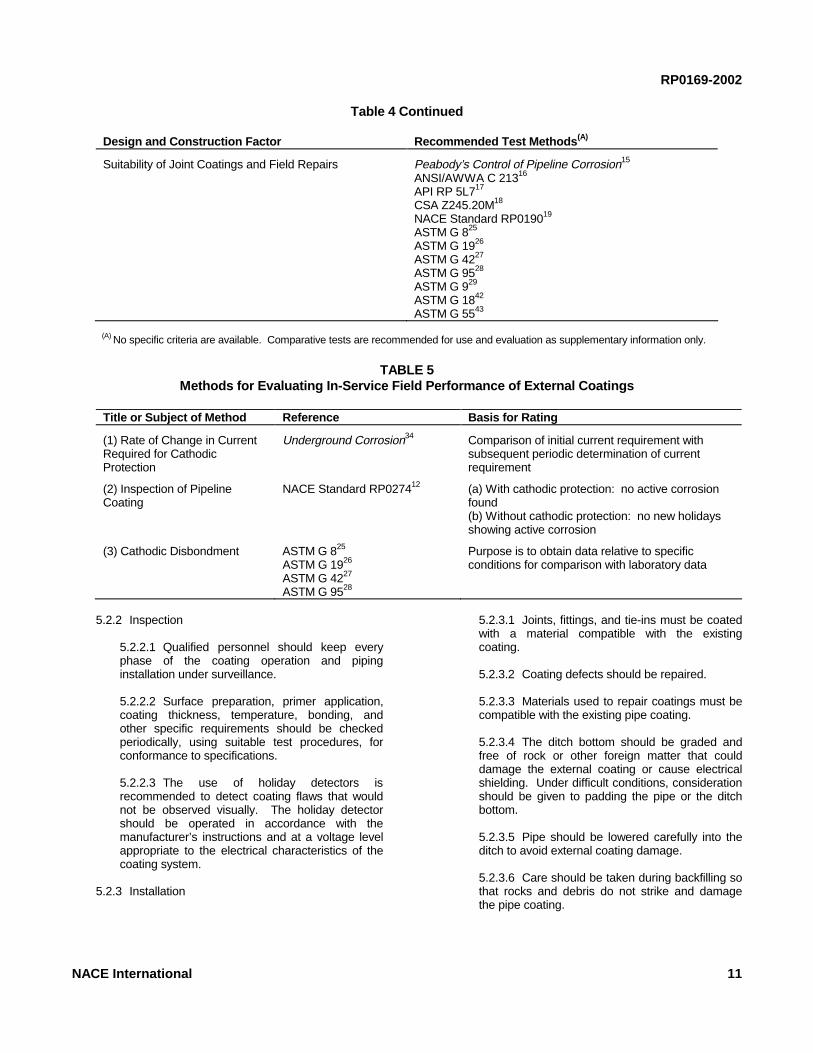
Table 4 Continued
Design and Construction Factor Recommended Test Methods (A)
Suitability of Joint Coatings and Field Repairs Peabody’s Control of Pipeline Corrosion15
ANSI/AWWA C 21316
API RP 5L717
CSA Z245.20M18
NACE Standard RP019019
ASTM G 825
ASTM G 1926
ASTM G 4227
ASTM G 9528
ASTM G 929
ASTM G 1842
ASTM G 5543
(A) No specific criteria are available. Comparative tests are recommended for use and evaluation as supplementary information only.
TABLE 5Methods for Evaluating In-Service Field Performance of External Coatings
Title or Subject of Method Reference Basis for Rating
(1) Rate of Change in CurrentRequired for CathodicProtection
Underground Corrosion34 Comparison of initial current requirement withsubsequent periodic determination of currentrequirement
(2) Inspection of PipelineCoating
NACE Standard RP027412 (a) With cathodic protection: no active corrosionfound(b) Without cathodic protection: no new holidaysshowing active corrosion
(3) Cathodic Disbondment ASTM G 825
ASTM G 1926
ASTM G 4227
ASTM G 9528
Purpose is to obtain data relative to specificconditions for comparison with laboratory data
5.2.2 Inspection
5.2.2.1 Qualified personnel should keep everyphase of the coating operation and pipinginstallation under surveillance.
5.2.2.2 Surface preparation, primer application,coating thickness, temperature, bonding, andother specific requirements should be checkedperiodically, using suitable test procedures, forconformance to specifications.
5.2.2.3 The use of holiday detectors isrecommended to detect coating flaws that wouldnot be observed visually. The holiday detectorshould be operated in accordance with themanufacturer’s instructions and at a voltage levelappropriate to the electrical characteristics of thecoating system.
5.2.3 Installation
5.2.3.1 Joints, fittings, and tie-ins must be coatedwith a material compatible with the existingcoating.
5.2.3.2 Coating defects should be repaired.
5.2.3.3 Materials used to repair coatings must becompatible with the existing pipe coating.
5.2.3.4 The ditch bottom should be graded andfree of rock or other foreign matter that coulddamage the external coating or cause electricalshielding. Under difficult conditions, considerationshould be given to padding the pipe or the ditchbottom.
5.2.3.5 Pipe should be lowered carefully into theditch to avoid external coating damage.
5.2.3.6 Care should be taken during backfilling sothat rocks and debris do not strike and damagethe pipe coating.
NACE International 11

RP0169-2002
5.2.3.7 Care shall be exercised when usingmaterials such as loose wrappers, nonconductingurethane foam, and rock shield around pipelinesas protection against physical damage or for otherpurposes, because these materials may create anelectrical shielding effect that would be detrimentalto the effectiveness of cathodic protection.
5.2.3.8 When a pipeline comes above ground, itmust be cleaned and externally coated, orjacketed with a suitable material, for the preventionof atmospheric corrosion.
5.3 Methods for Evaluating External Coating Systems
5.3.1 Established Systems Proven by Successful Use
5.3.1.1 Visual and electrical inspection ofin-service pipeline coatings should be used toevaluate the performance of an external coatingsystem. These inspections can be conductedwherever the pipeline is excavated or at bell holesmade for inspection purposes.
5.3.2 Established or Modified Systems for NewEnvironments
5.3.2.1 This method is intended for use whenexternal coating systems will continue to be usedand are qualified under Paragraph 5.3.1, but whenapplication will be extended to new environmentsor when it is desired to revise a system to makeuse of new developments.
5.3.2.1.1 The use of applicable materialrequirements, material specifications,standards, and recommended practices forapplication, as given in Table 1, isrecommended.
5.3.2.1.2 The use of applicable references inTable 2 is recommended unless previouslycovered in applicable references in Table 1.
5.3.3 New External Coating System Qualification
________________________________________
5.3.3.1 The purpose of this method is to qualify anew external coating material by subjecting it tolaboratory tests appropriate for the intendedservice. After laboratory tests have beenconducted and indicate that the external coatingsystem appears to be suitable, application andinstallation are conducted in accordance withrecommended practices. In-service fieldperformance tests are made to confirm thesuccess of the previous steps. The steps of themethod are (1) laboratory tests, (2) applicationunder recommended practices, (3) installationunder recommended practices, and (4) in-servicefield performance tests. If good results areobtained after five years, only Steps 2 and 3 arerequired thereafter.
5.3.3.1.1 Applicable sections of Tables 3 and4 are recommended for the initial laboratorytest methods.
5.3.3.1.2 Applicable sections of Tables 1 and2 are recommended for conditional use duringSteps 2 and 3.
5.3.3.1.3 During a period of five years ormore, the use of the evaluation methodsgiven in Table 5, Item 1 or 2 arerecommended. The test method in Item 3may be used as a supplementary means forobtaining data for correlation with laboratorytests.
5.3.4 Method for Evaluating an External CoatingSystem by In-Service Field Performance Only
5.3.4.1 The purpose of this method is to qualify anexternal coating system when none of the firstthree methods given in Paragraph 5.3 has been orwill be used. It is intended that this method shouldbe limited to minor pilot installations.
5.3.4.1.1 The use of at least one of the firsttwo methods given in Table 5 isrecommended on the basis of at least oneinvestigation per year for five consecutiveyears.
________________________________
Section 6: Criteria and Other Considerations for Cathodic Protection
6.1 Introduction
6.1.1 This section lists criteria and otherconsiderations for cathodic protection that indicate,when used either separately or in combination, whetheradequate cathodic protection of a metallic pipingsystem has been achieved (see also Section 1,Paragraphs 1.2 and 1.4).
6.1.2 The effectiveness of cathodic protection or otherexternal corrosion control measures can be confirmedby visual observation, by measurements of pipe wallthickness, or by use of internal inspection devices.Because such methods sometimes are not practical,meeting any criterion or combination of criteria in thissection is evidence that adequate cathodic protectionhas been achieved. When excavations are made for
12 NACE International

any purpose, the pipe should be inspected for evidenceof corrosion and/or coating condition.
6.1.3 The criteria in this section have been developedthrough laboratory experiments and/or verified byevaluating data obtained from successfully operatedcathodic protection systems. Situations in which asingle criterion for evaluating the effectiveness ofcathodic protection may not be satisfactory for allconditions may exist. Often a combination of criteria isneeded for a single structure.
6.1.4 Sound engineering practices shall be used todetermine the methods and frequency of testingrequired to satisfy these criteria.
6.1.5 Corrosion leak history is valuable in assessingthe effectiveness of cathodic protection. Corrosion leakhistory by itself, however, shall not be used todetermine whether adequate levels of cathodicprotection have been achieved unless it is impracticalto make electrical surveys.
6.2 Criteria
6.2.1 It is not intended that persons responsible forexternal corrosion control be limited to the criteria listedbelow. Criteria that have been successfully applied onexisting piping systems can continue to be used onthose piping systems. Any other criteria used mustachieve corrosion control comparable to that attainedwith the criteria herein.
6.2.2 Steel and Cast Iron Piping
6.2.2.1 External corrosion control can beachieved at various levels of cathodic polarizationdepending on the environmental conditions.However, in the absence of specific data thatdemonstrate that adequate cathodic protectionhas been achieved, one or more of the followingshall apply:
6.2.2.1.1 A negative (cathodic) potential of atleast 850 mV with the cathodic protectionapplied. This potential is measured withrespect to a saturated copper/copper sulfatereference electrode contacting the electrolyte.Voltage drops other than those across thestructure-to-electrolyte boundary must beconsidered for valid interpretation of thisvoltage measurement.
NOTE: Consideration is understood to meanthe application of sound engineering practicein determining the significance of voltagedrops by methods such as:
6.2.2.1.1.1 Measuring or calculatingthe voltage drop(s);
RP0169-2002
6.2.2.1.1.2 Reviewing the historicalperformance of the cathodic protectionsystem;
6.2.2.1.1.3 Evaluating the physical andelectrical characteristics of the pipe andits environment; and
6.2.2.1.1.4 Determining whether or notthere is physical evidence of corrosion.
6.2.2.1.2 A negative polarized potential (seedefinition in Section 2) of at least 850 mVrelative to a saturated copper/copper sulfatereference electrode.
6.2.2.1.3 A minimum of 100 mV of cathodicpolarization between the structure surfaceand a stable reference electrode contactingthe electrolyte. The formation or decay ofpolarization can be measured to satisfy thiscriterion.
6.2.2.2 Special Conditions
6.2.2.2.1 On bare or ineffectively coatedpipelines when long-line corrosion activity is ofprimary concern, the measurement of a netprotective current at predetermined currentdischarge points from the electrolyte to thepipe surface, as measured by an earth currenttechnique, may be sufficient.
6.2.2.2.2 In some situations, such as thepresence of sulfides, bacteria, elevatedtemperatures, acid environments, anddissimilar metals, the criteria in Paragraph6.2.2.1 may not be sufficient.
6.2.2.2.3 When a pipeline is encased inconcrete or buried in dry or aerated high-resistivity soil, values less negative than thecriteria listed in Paragraph 6.2.2.1 may besufficient.
6.2.2.3 PRECAUTIONARY NOTES
6.2.2.3.1 The earth current technique is oftenmeaningless in multiple pipe rights-of-way, inhigh-resistivity surface soil, for deeply buriedpipe, in stray-current areas, or where localcorrosion cell action predominates.
6.2.2.3.2 Caution is advised against usingpolarized potentials less negative than -850mV for cathodic protection of pipelines whenoperating pressures and conditions areconducive to stress corrosion cracking (seereferences on stress corrosion cracking at theend of this section).
NACE International 13

RP0169-2002
6.2.2.3.3 The use of excessive polarizedpotentials on externally coated pipelinesshould be avoided to minimize cathodicdisbondment of the coating.
6.2.2.3.4 Polarized potentials that result inexcessive generation of hydrogen should beavoided on all metals, particularly higher-strength steel, certain grades of stainlesssteel, titanium, aluminum alloys, andprestressed concrete pipe.
6.2.3 Aluminum Piping
6.2.3.1 The following criterion shall apply: aminimum of 100 mV of cathodic polarizationbetween the structure surface and a stablereference electrode contacting the electrolyte. Theformation or decay of this polarization can be usedin this criterion.
6.2.3.2 PRECAUTIONARY NOTES
6.2.3.2.1 Excessive Voltages: Notwith-standing the minimum criterion in Paragraph6.2.3.1, if aluminum is cathodically protectedat voltages more negative than -1,200 mVmeasured between the pipe surface and asaturated copper/copper sulfate referenceelectrode contacting the electrolyte andcompensation is made for the voltage dropsother than those across the pipe-electrolyteboundary, it may suffer corrosion as the resultof the buildup of alkali on the metal surface.A polarized potential more negative than -1,200 mV should not be used unless previoustest results indicate that no appreciablecorrosion will occur in the particularenvironment.
6.2.3.2.2 Alkaline Conditions: Aluminummay suffer from corrosion under high-pHconditions and application of cathodicprotection tends to increase the pH at themetal surface. Therefore, carefulinvestigation or testing should be done beforeapplying cathodic protection to stop pittingattack on aluminum in environments with anatural pH in excess of 8.0.
6.2.4 Copper Piping
6.2.4.1 The following criterion shall apply: aminimum of 100 mV of cathodic polarizationbetween the structure surface and a stablereference electrode contacting the electrolyte. Theformation or decay of this polarization can be usedin this criterion.
6.2.5 Dissimilar Metal Piping
6.2.5.1 A negative voltage between all pipesurfaces and a stable reference electrodecontacting the electrolyte equal to that required forthe protection of the most anodic metal should bemaintained.
6.2.5.2 PRECAUTIONARY NOTE
6.2.5.2.1 Amphoteric materials that could bedamaged by high alkalinity created bycathodic protection should be electricallyisolated and separately protected.
6.3 Other Considerations
6.3.1 Methods for determining voltage drop(s) shall beselected and applied using sound engineeringpractices. Once determined, the voltage drop(s) maybe used for correcting future measurements at thesame location, providing conditions such as pipe andcathodic protection system operating conditions, soilcharacteristics, and external coating quality remainsimilar. (Note: Placing the reference electrode next tothe pipe surface may not be at the pipe-electrolyteinterface. A reference electrode placed at an externallycoated pipe surface may not significantly reduce soilvoltage drop in the measurement if the nearest coatingholiday is remote from the reference electrodelocation.)
6.3.2 When it is impractical or consideredunnecessary to disconnect all current sources tocorrect for voltage drop(s) in the structure-to-electrolytepotential measurements, sound engineering practicesshould be used to ensure that adequate cathodicprotection has been achieved.
6.3.3 When feasible and practicable, in-line inspectionof pipelines may be helpful in determining the presenceor absence of pitting corrosion damage. Absence ofexternal corrosion damage or the halting of its growthmay indicate adequate external corrosion control. Thein-line inspection technique, however, may not becapable of detecting all types of external corrosiondamage, has limitations in its accuracy, and may reportas anomalies items that are not external corrosion. Forexample, longitudinal seam corrosion and generalcorrosion may not be readily detected by in-lineinspection. Also, possible thickness variations, dents,gouges, and external ferrous objects may be detectedas corrosion. The appropriate use of in-line inspectionmust be carefully considered.
6.3.4 Situations involving stray currents and strayelectrical gradients that require special analysis mayexist. For additional information, see Section 9,“Control of Interference Currents.”
6.4 Alternative Reference Electrodes
6.4.1 Other standard reference electrodes may besubstituted for the saturated copper/copper sulfate
14 NACE International

reference electrode. Two commonly used referenceelectrodes are listed below along with their voltageequivalent (at 25°C [77°F]) to -850 mV referred to asaturated copper/copper sulfate reference electrode:
6.4.1.1 Saturated KCl calomel referenceelectrode: -780 mV; and
6.4.1.2 Saturated silver/silver chloride referenceelectrode used in 25 ohm-cm seawater: -800 mV.
______________________________________
RP0169-2002
6.4.2 In addition to these standard referenceelectrodes, an alternative metallic material or structuremay be used in place of the saturated copper/coppersulfate reference electrode if the stability of itselectrode potential is ensured and if its voltageequivalent referred to a saturated copper/coppersulfate reference electrode is established.
__________________________________
Bibliography for Section 6
Criteria for Copper
Schwerdtfeger, W.J. “Criteria for Cathodic Protection—Highly Resistant Copper Deteriorates in SeverelyCorrosive Soil.” Materials Protection 57, 9 (1968): p.43.
Criteria for Aluminum
CP1021. “Code of Practice for Cathodic Protection.”London, England: BSI,(3) August, 1973, pp. 13-14.
DIN30 676 (latest revision). “Design and Application ofCathodic Protection of External Surfaces.” Berlin,Germany: Deutsches Institut fur Normung, October,1985.
NACE Publication 2M363 (withdrawn). “RecommendedPractice for Cathodic Protection of Aluminum PipeBuried in Soil or Immersed in Water.” MaterialsPerformance 2, 10 (1963): p. 106.
Schwerdtfeger, W.J. “Effects of Cathodic Current on theCorrosion of An Aluminum Alloy.” National Bureau ofStandards(4) Journal of Research 68c (Oct.-Dec. 1964):p. 283.
Criteria for Steel and Cast Iron
Doremus, E.P., and T.L. Canfield. “The Surface PotentialSurvey Can Detect Pipeline Corrosion Damage.”Materials Protection 6, 9 (1967): p. 33.
Ewing, S.P. “Potential Measurements for Determination ofCathodic Protection Requirements.” CORROSION 7, 12(1951): p. 410.
Haycock, E.W. “Current Requirements for CathodicProtection of Oil Well Casing.” CORROSION 13, 11(1957): p. 767.
Kuhn, R.C. “Cathodic Protection of Underground PipelinesAgainst Soil Corrosion.” American Petroleum InstituteProceedings IV, 14 (1953): p. 153.
McCollum, B., and K.H. Logan. National Bureau ofStandards Technical Paper No. 351, 1927.
Romanoff, M. Underground Corrosion. Houston, TX:NACE, 1989.
Pearson, J.M. “Electrical Instruments and Measurement inCathodic Protection.” CORROSION 3, 11 (1947): p. 549.
Pearson, J.M. “Null Methods Applied to CorrosionMeasurements.” Transactions of the ElectrochemicalSociety 81 (1942): p. 485.
Schwerdtfeger, W.J., and O.N. McDorman. “Potential andCurrent Requirements for the Cathodic Protection ofSteel in Soils.” CORROSION 8, 11 (1952): p. 391.
Sudrabin, L.P., and F.W. Ringer. “Some Observations onCathodic Protection Criteria.” Corrosion 13, 5 (1957) p.351t. Discussion on this paper CORROSION 13, 12(1957): p. 835t.
Additional References
Barlo, T.J., and W.E. Berry. “A Reassessment of the -0.85V and 100 mV Polarization Criteria for CathodicProtection of Steel Buried in Soils. Ninth InternationalCongress on Metallic Corrosion 4, (1984): June 7.National Research Council Canada.(5)
Barlo, T.J., and W.E. Berry. “An Assessment of the CurrentCriteria for Cathodic Protection of Buried Steel Pipes.”Materials Performance 23, 9 (1984).
Barlo, T.J., and R.R. Fessler. “Interpretation of True Pipe-to-Soil Potentials on Coated Pipelines with Holidays.”CORROSION/83, paper no. 292. Houston, TX: NACE,1983.
NACE International 15
___________________________(3) British Standards Institution (BSI), British Standards House, 389 Chiswick High Road, London W4 4AL, United Kingdom.(4) National Institute of Standards and Technology (NIST) (formerly National Bureau of Standards), Gaithersburg, MD 20899.(5) National Research Council Canada (NRC), 1200 Montreal Road, Ottawa, Ontario K1A 0R6, CANADA.

RP0169-2002
Barlo, T.J., and R.R. Fessler. “Investigation of Techniquesto Determine the True Pipe-to-Soil Potential of a BuriedPipeline.” AGA(6) Project PR-3-93, 1979 AnnualReport, May, 1980.
Cathodic Protection Criteria—A Literature Survey. Houston,TX: NACE, 1989.
Comeaux, R.V. “The Role of Oxygen in Corrosion andCathodic Protection.” CORROSION 8, 9 (1952): pp. 305-309.
Compton, K.G. “Criteria and Their Application for CathodicProtection of Underground Structures.” MaterialsProtection 4, 8 (1965): pp. 93-96.
Dabkowski, J. “Assessing the Cathodic Protection Levels ofWell Casings.” AGA Project 151-106, Final Report,January 1983: pp. 3-92.
Dexter, S.C., L.N. Moettus, and K.E. Lucas. “On theMechanism of Cathodic Protection.” CORROSION 41, 10(1985).
“Field Testing the Criteria for Cathodic Protection.” AGAInterim Report PR-151-163, December, 1987.
Fischer, K.P. “Cathodic Protection in Saline MudContaining Sulfate Reducing Bacteria.” MaterialsPerformance 20, 10 (1981): pp. 41-46.
Gummow, R.A. “Cathodic Protection Criteria—A CriticalReview of NACE Standard RP0169.” MaterialsPerformance 25, 9 (1986): pp. 9-16.
Hoey, G.R., and M. Cohen. “Cathodic Protection of Iron inthe Temperature Range 25-92°C.” CORROSION 14, 4(1958): pp. 200t-202t.
Holler, H.D. “Studies on Galvanic Couples II-SomePotential-Current Relations in Galvanic Corrosion.”Journal of the Electrochemical Society September(1950): pp. 277-282.
Howell, R.P. “Potential Measurements in CathodicProtection Designs.” CORROSION 8 (1952).
Jones, D. “Electrochemical Fundamentals of CathodicProtection.” CORROSION/87, paper no. 317.Houston, TX: NACE, 1987.
Kasahara, K., T. Sato, and H. Adachi. “Results ofPolarization Potential and Current Density Surveys onExisting Buried Pipelines.” Materials Performance 19,9 (1980): pp. 45-51.
Kehn, G.R., and E.J. Wilhelm. “Current Requirements forthe Cathodic Protection of Steel in Dilute AqueousSolutions.” CORROSION 7, 5 (1951): pp. 156-160.
__________________________________________
Koybayaski, T. “Effect of Environmental Factors on theProtective Potential of Steel.” Proceedings of the FifthInternational Congress on Metallic Corrosion. Houston,TX: NACE, 1980.
Krivian, L. “Application of the Theory of Cathodic Protectionto Practical Corrosion Systems.” British CorrosionJournal, 19, 1 (1984).
Kuhn, R.J. “Cathodic Protection on Texas Gas Systems.”AGA Annual Conference. Held Detroit, MI, April 1950.
Lattin, B.C. “The Errors of Your Ways (Fourteen Pitfalls forCorrosion Engineers and Technicians to Avoid).”Materials Performance 20, 3 (1981): p. 30.
Logan, K.H. “Comparison of Cathodic Protection TestMethods.” CORROSION 10, 7 (1959).
Logan, K.H. “Underground Corrosion.” National Bureau ofStandards Circular C450, November, 1945, pp. 249-278.
Logan, K.H. “The Determination of the Current Required forCathodic Protection.” National Bureau of StandardsSoil Corrosion Conference, March, 1943.
Martin, B.A. “Cathodic Protection: The Ohmic Componentof Potential Measurements—Laboratory Determinationwith a Polarization Probe in Aqueous Environments.”Materials Performance 20, 1 (1981): p. 52.
Martin, B.A., and J.A. Huckson. “New Developments inInterference Testing.” Industrial Corrosion 4, 6 (1986):pp. 26-31.
Mears and Brown. “A Theory of Cathodic Protection.”Transactions of the Electrochemical Society 74 (1938):p. 527.
Morgan, J. Cathodic Protection. Houston, TX: NACE,1987.
NACE Technical Committee T-2C Report (withdrawn).“Criteria for Adequate Cathodic Protection of Coated,Buried, or Submerged Steel Pipe Lines and SimilarSteel Structures.” CORROSION 14,13 (1958): p. 561t.
Pearson, J.M. “Concepts and Methods of CathodicProtection.” The Petroleum Engineer 15, 6 (1944): p.218; and 15, 7 (1944): p. 199.
Pourbaix, M. Atlas of Electrochemical Equilibria in AqueousSolutions. Houston, TX: NACE, 1974, p. 319.
Prinz, W. “Close Interval Potential Survey of BuriedPipelines, Methods and Experience.” UK Corrosion‘86, p. 67.
16 NACE International
(6) American Gas Association (AGA), 1515 Wilson Blvd., Arlington, VA 22209.
Riordan, M.A. “The Electrical Survey—What It Won’t Do.”Materials Performance 17, 11 (1978): pp. 38-41.
Riordan, M.A., and R.P. Sterk. “Well Casing as anElectrochemical Network in Cathodic ProtectionDesign.” Materials Performance 2, 7 (1963): pp. 58-68.
Schaschl, E., and G.A. Marsh. “Placement of ReferenceElectrode and Impressed Current Anode Effect onCathodic Protection of Steel in a Long Cell.” MaterialsPerformance 13, 6 (1974): pp. 9-11.
Stern, M. “Fundamentals of Electrode Processes inCorrosion.” CORROSION 13, 11 (1957): pp. 775t-782t.
CEA 54277. “State-of-the-Art Report, Specialized Surveysfor Buried Pipelines.” Houston, TX: NACE, 1987
Thompson, N.G., and T.J. Barlo. “Fundamental Process ofCathodically Protecting Steel Pipelines.” InternationalGas Research Conference, 1983.
Toncre, A.C. “A Review of Cathodic Protection Criteria.”Proceeding of Sixth European Congress on MetallicCorrosion. Held London, England, September, 1977,pp. 365-372.
Van Nouhuys, H.C. “Cathodic Protection and HighResistivity Soil.” CORROSION 9 (1953): pp. 448-458.
Van Nouhuys, H.C. “Cathodic Protection and HighResistivity Soil—A Sequel.” CORROSION 14, 12 (1958):pp. 583-587.
Von Baekmann, W., A. Ballest, and W. Prinz. “NewDevelopment in Measuring the Effectiveness ofCathodic Protection.” Corrosion Australasia, February,1983.
Von Baekmann, W., and W. Schwenk. Handbook ofCathodic Protection. Portellis Press, 1975, Chapter 2.
___________________________________
RP0169-2002
Webster, R.D. “Compensating for the IR Drop Componentin Pipe-to-Soil Potential Measurements.” MaterialsPerformance 26, 10 (1987): pp. 38-41.
Wyatt, B.S., K.C. Lax. “Close Interval Overline PolarizedPotential Surveys of Buried Pipelines.” UK CorrosionConference, 1985.
Stress Corrosion Cracking
Barlo, T.J., et al. “An Assessment of the Criteria forCathodic Protection of Buried Pipelines.” AGA FinalReport, Project PR-3-129, 1983.
Barlo, T.J., et al. “Controlling Stress-Corrosion Cracking byCathodic Protection.” AGA Annual Report, Project-3-164, 1984.
Parkins, R.N., et al. “Hydrogen Gas Evolution FromCathodically Protected Surfaces.” CORROSION 41(1985): pp. 389-397.
Parkins, R.N., and R.R. Fessler. “Stress CorrosionCracking of High Pressure Gas TransmissionPipelines.” Materials in Engineering Applications 1, pp.80-96.
Parkins, R.N., and R.R. Fessler. “Line Pipe StressCorrosion Cracking—Mechanisms and Remedies.”CORROSION/86 paper no. 320. Houston, TX: NACE,1986.
Parkins, R.N., A.J. Markworth, and J.H. Holbrook.“Hydrogen Gas Evolution From Cathodically ProtectedPipeline Steel Surfaces Exposed to Chloride-SulfateSolutions.” CORROSION 44 (1988): pp. 572-580.
McCaffrey, W.R. “Effect of Overprotection on PipelineCoatings.” Materials Protection and Performance 12, 2(1973): p. 10.
PR-15-427. “An Assessment of Stress Corrosion Cracking(SCC) Research for Line Pipe Steels.” AGA, 1985.
_____________________________________
Section 7: Design of Cathodic Protection Systems
7.1 Introduction
7.1.1 This section recommends procedures fordesigning cathodic protection systems that will provideeffective external corrosion control by satisfying one ormore of the criteria listed in Section 6 and exhibitingmaximum reliability over the intended operating life ofthe systems.
7.1.2 In the design of a cathodic protection system,the following should be considered:
7.1.2.1 Recognition of hazardous conditionsprevailing at the proposed installation site(s) andthe selection and specification of materials andinstallation practices that ensure safe installationand operation.
7.1.2.2 Specification of materials and installationpractices to conform to the latest editions ofapplicable codes, National Electrical Manufac-turers Association (NEMA)(7) standards, National
NACE International 17
___________________________(7) National Electrical Manufacturers Association (NEMA), 2101 L St., NW, Washington, DC 20037.

RP0169-2002
Electrical Code (NEC),(8) appropriate internationalstandards, and NACE standards.
7.1.2.3 Selection and specification of materialsand installation practices that ensure dependableand economical operation throughout the intendedoperating life.
7.1.2.4 Selection of locations for proposedinstallations to minimize currents or earth potentialgradients, which can cause detrimental effects onforeign buried or submerged metallic structures.
7.1.2.5 Cooperative investigations to determinemutually satisfactory solution(s) of interferenceproblems (see Section 9).
7.1.2.6 Special consideration should be given tothe presence of sulfides, bacteria, disbondedcoatings, thermal insulating coatings, elevatedtemperatures, shielding, acid environments, anddissimilar metals.
7.1.2.7 Excessive levels of cathodic protectionthat can cause external coating disbondment andpossible damage to high-strength steels as aresult of hydrogen evolution should be avoided.
7.1.2.8 When amphoteric metals are involved,care should be taken so that high-pH conditionsthat could cause cathodic corrosion of the metalare not established.
7.2 Major objectives of cathodic protection system designinclude the following:
7.2.1 To provide sufficient current to the structure tobe protected and distribute this current so that theselected criteria for cathodic protection are effectivelyattained;
7.2.2 To minimize the interference currents onneighboring underground structures (see Section 9);
7.2.3 To provide a design life of the anode systemcommensurate with the required life of the protectedstructure, or to provide for periodic rehabilitation of theanode system;
7.2.4 To provide adequate allowance for anticipatedchanges in current requirements with time;
7.2.5 To install anodes where the possibility ofdisturbance or damage is minimal; and
7.2.6 To provide adequate monitoring facilities to testand evaluate the system performance.
7.3 Information Useful for Design
7.3.1 Useful piping system specifications andinformation include the following:
7.3.1.1 Route maps and atlas sheets;
7.3.1.2 Construction dates;
7.3.1.3 Pipe, fittings, and other appurtenances;
7.3.1.4 External coatings;
7.3.1.5 Casings;
7.3.1.6 Corrosion control test stations;
7.3.1.7 Electrically isolating devices;
7.3.1.8 Electrical bonds; and
7.3.1.9 Aerial, bridge, and underwater crossings.
7.3.2 Useful information on piping system siteconditions includes the following:
7.3.2.1 Existing and proposed cathodic protectionsystems;
7.3.2.2 Possible interference sources (seeSection 9);
7.3.2.3 Special environmental conditions;
7.3.2.4 Neighboring buried metallic structures(including location, ownership, and corrosioncontrol practices);
7.3.2.5 Structure accessibility;
7.3.2.6 Power availability; and
7.3.2.7 Feasibility of electrical isolation fromforeign structures.
7.3.3 Useful information from field surveys, corrosiontest data, and operating experience includes thefollowing:
7.3.3.1 Protective current requirements to meetapplicable criteria;
7.3.3.2 Electrical resistivity of the electrolyte;
7.3.3.3 Electrical continuity;
7.3.3.4 Electrical isolation;
7.3.3.5 External coating integrity;
7.3.3.6 Cumulative leak history;
18 NACE International
__________________________________________
(8) National Fire Protection Association, Batterymarch Park, Quincy, MA 02269.

7.3.3.7 Interference currents;
7.3.3.8 Deviation from construction specifications;and
7.3.3.9 Other maintenance and operating data.
7.3.4 Field survey work prior to actual application ofcathodic protection is not always required if priorexperience or test data are available to estimatecurrent requirements, electrical resistivities of theelectrolyte, and other design factors.
7.4 Types of Cathodic Protection Systems
7.4.1 Galvanic Anode Systems
7.4.1.1 Galvanic anodes can be made ofmaterials such as alloys of magnesium, zinc, oraluminum. The anodes are connected to the pipe,either individually or in groups. Galvanic anodesare limited in current output by the anode-to-pipedriving voltage and the electrolyte resistivity.
7.4.2 Impressed Current Anode Systems
7.4.2.1 Impressed current anodes can be ofmaterials such as graphite, high-silicon cast iron,lead-silver alloy, precious metals, or steel. Theyare connected with an insulated cable, eitherindividually or in groups, to the positive terminal ofa direct-current (DC) source, such as a rectifier orgenerator. The pipeline is connected to thenegative terminal of the DC source.
7.5 Considerations influencing selection of the type ofcathodic protection system include the following:
7.5.1 Magnitude of protective current required;
7.5.2 Stray currents causing significant potentialfluctuations between the pipeline and earth that maypreclude the use of galvanic anodes;
7.5.3 Effects of cathodic protection interferencecurrents on adjacent structures that may limit the use ofimpressed current cathodic protection systems;
7.5.4 Availability of electrical power;
7.5.5 Physical space available, proximity of foreignstructures, easement procurement, surface conditions,presence of streets and buildings, river crossings, andother construction and maintenance concerns.
7.5.6 Future development of the right-of-way area andfuture extensions to the pipeline system;
7.5.7 Costs of installation, operation, andmaintenance; and
7.5.8 Electrical resistivity of the environment.
RP0169-2002
7.6 Factors Influencing Design of Cathodic ProtectionSystems
7.6.1 Various anode materials have different rates ofdeterioration when discharging a given current densityfrom the anode surface in a specific environment.Therefore, for a given current output, the anode lifedepends on the environment and anode material, aswell as the anode weight and the number of anodes inthe cathodic protection system. Established anodeperformance data may be used to calculate theprobable deterioration rate.
7.6.2 Data on the dimensions, depth, andconfiguration of the anodes and the electrolyteresistivity may be used to calculate the resultantresistance to electrolyte of the anode system.Formulas and graphs relating to these factors areavailable in the literature and from manufacturers.
7.6.3 Design of galvanic anode systems shouldconsider anode-to-pipe potential, electrolyte resisivity,current output, and in special cases, anode lead-wireresistance. A separate design for each anode oranode system may not be necessary.
7.6.4 Galvanic anode performance in most soils canbe improved by using special backfill material.Mixtures of gypsum, bentonite, and anhydrous sodiumsulfate are most commonly used.
7.6.5 The number of impressed current anodesrequired can be reduced and their useful lifelengthened by the use of special backfill around theanodes. The most common materials are coal coke,calcined petroleum coke, and natural or manufacturedgraphite.
7.6.6 In the design of an extensive distributed-anodeimpressed current system, the voltage and currentattenuation along the anode-connecting (header) cableshould be considered. In such cases, the designobjective is to optimize anode system length, anodespacing and size, and cable size in order to achieveefficient external corrosion control at the extremities ofthe protected structure.
7.6.7 When it is anticipated that entrapment of gasgenerated by anodic reactions could impair the abilityof the impressed current groundbed to deliver therequired current, suitable provisions should be madefor venting the anodes. For the same current output ofthe system, an increase in the surface area of thespecial backfill material or an increase in the number ofanodes may reduce gas blockage.
7.6.8 When it is anticipated that electroosmotic effectscould impair the ability of the impressed currentgroundbed to deliver the required current output,suitable provisions should be made to ensure adequatesoil moisture around the anodes. Increasing thenumber of impressed current anodes or increasing the
NACE International 19

RP0169-2002
surface area of the special backfill materials mayfurther reduce the electroosmotic effect.
7.7 Design Drawings and Specifications
7.7.1 Suitable drawings should be prepared todesignate the overall layout of the piping to beprotected and the location of significant items ofstructure hardware, corrosion control test stations,electrical bonds, electrical isolation devices, andneighboring buried or submerged metallic structures.
7.7.2 Layout drawings should be prepared for eachimpressed current cathodic protection installation,showing the details and location of the components of
______________________________________
the cathodic protection system with respect to theprotected structure(s) and to major physical landmarks.These drawings should include right-of-wayinformation.
7.7.3 The locations of galvanic anode installationsshould be recorded on drawings or in tabular form, withappropriate notes on anode type, weight, spacing,depth, and backfill.
7.7.4 Specifications should be prepared for allmaterials and installation practices that are to beincorporated in construction of the cathodic protectionsystem.
__________________________________
Bibliography for Section 7
Anode Resistance Fundamentals and Applications—Classic Papers and Reviews. Houston, TX: NACE,1986.
Baboian, R., P.F. Drew, and K. Kawate. “Design ofPlatinum Clad Wire Anodes for Impressed CurrentProtection.” Materials Performance 23, 9 (1984): pp.31-35.
Collected Papers on Cathodic Protection CurrentDistribution. Houston, TX: NACE, 1989.
Doremus, G., and J.G. Davis. “Marine Anodes: The Oldand New.” Materials Performance 6, 1 (1967): p. 30.
Dwight, H.B. “Calculations for Resistance to Ground.”Electrical Engineering 55 (1936): p. 1319.
George P.F., J.J. Newport, and J.L. Nichols. “A HighPotential Magnesium Anode.” CORROSION 12, 12(1956): p. 627t.
Jacobs, J.A. “A Comparison of Anodes for ImpressedCurrent Systems.” NACE Canadian Region WesternConference, Edmonton, Alberta, Canada, February,1980.
Kurr, G.W. “Zinc Anodes—Underground Uses for CathodicProtection and Grounding.” Materials Performance 18,4 (1979): pp. 34-41.
NACE Publication 2B160 (withdrawn). “Use of High SiliconCast Iron for Anodes.” CORROSION 16, 2 (1960): p. 109.
NACE Publication 2B156 (withdrawn). “Final Report onFour Annual Anode Inspections.” CORROSION 12, 1(1956): p. 63.
Parker, M.E. Pipe Line Corrosion and CathodicProtection—A Field Manual. Houston, TX: GulfPublishing Company, 1962.
Robinson, H.A., and P.F. George. “Effect of Alloying andImpurity Elements in Magnesium Cast Anodes.”CORROSION 10, 6 (1954): p. 182.
Rudenberg, R. “Grounding Principles and Practices.”Electrical Engineering 64 (1945): p. 1.
Schreiber, C.F., and G.L. Mussinelli. “Characteristics andPerformance of the LIDA Impressed Current System inNatural Waters and Saline Muds.” CORROSION/86,paper no. 287. Houston, TX: NACE, 1986.
Sunde, E.D.. Earth Conduction Effects in TransmissionSystems. New York, NY: Dover Publications, 1968.
20 NACE International

RP0169-2002
________________________________________________________________________
Section 8: Installation of Cathodic Protection Systems
8.1 Introduction
8.1.1 This section recommends procedures that willresult in the installation of cathodic protection systemsthat achieve protection of the structure. The designconsiderations recommended in Sections 4 and 7should be followed.
8.2 Construction Specifications
8.2.1 All construction work on cathodic protectionsystems should be performed in accordance withconstruction drawings and specifications. Theconstruction specifications should be in accordancewith recommended practices in Sections 4 and 7.
8.3 Construction Supervision
8.3.1 All construction work on cathodic protectionsystems should be performed under the surveillance oftrained and qualified personnel to verify that theinstallation is in strict accordance with the drawings andspecifications. Exceptions may be made only with theapproval of qualified personnel responsible for externalcorrosion control.
8.3.2 All deviations from construction specificationsshould be noted on as-built drawings.
8.4 Galvanic Anodes
8.4.1 Inspection, Handling, and Storage
8.4.1.1 Packaged anodes should be inspectedand steps taken to ensure that backfill materialcompletely surrounds the anode. The individualcontainer for the backfill material and anodeshould be intact. If individually packaged anodesare supplied in waterproof containers, thecontainers must be removed before installation.Packaged anodes should be kept dry duringstorage.
8.4.1.2 Lead wire must be securely connected tothe anode. Lead wire should be inspected forassurance that it is not damaged.
8.4.1.3 Other galvanic anodes, such as theunpackaged “bracelet” or ribbon type, should beinspected to ensure that dimensions conform todesign specifications and that any damage duringhandling does not affect application. If a coating isused on bands and the inner side of braceletanode segments, it should be inspected and, ifdamaged, repaired before the anodes areinstalled.
8.4.2 Installing Anodes
8.4.2.1 Anodes should be installed according toconstruction specifications.
8.4.2.2 Packaged galvanic anodes should bebackfilled with appropriately compacted material.When anodes and special chemical backfill areprovided separately, anodes should be centered inspecial backfill, which should be compacted priorto backfilling. Care should be exercised during alloperations so that lead wires and connections arenot damaged. Sufficient slack should exist in leadwires to avoid strain.
8.4.2.3 When anodes in bracelet form are used,external pipe coating beneath the anode should befree of holidays. Care should be taken to preventdamage to the external coating when braceletanodes are installed. After application of concrete(if used) to pipe, all coating and concrete shouldbe removed from the anode surface. If reinforcedconcrete is used, there must be no metalliccontact between the anode and the reinforcingmesh or between the reinforcing mesh and thepipe.
8.4.2.4 When a ribbon-type anode is used, it canbe trenched or plowed in, with or without specialchemical backfill as required, generally parallel tothe section of pipeline to be protected.
8.5 Impressed Current Systems
8.5.1 Inspection and Handling
8.5.1.1 The rectifier or other power source shouldbe inspected to ensure that internal connectionsare mechanically secure and that the unit is free ofdamage. Rating of the DC power source shouldcomply with the construction specification. Careshould be exercised in handling and installing thepower source.
8.5.1.2 Impressed current anodes should beinspected for conformance to specificationsconcerning anode material, size, length of leadcable, anode lead connection, and integrity of seal.Care should be exercised to avoid cracking ordamaging anodes during handling and installation.
8.5.1.3 All cables should be carefully inspected todetect defects in insulation. Care should be takento avoid damage to cable insulation. Defects inthe cable insulation must be repaired.
NACE International 21

RP0169-2002
8.5.1.4 Anode backfill material should conform tospecifications.
8.5.2 Installation Provisions
8.5.2.1 A rectifier or other power source should beinstalled so that the possibility of damage orvandalism is minimized.
8.5.2.2 Wiring to rectifiers shall comply with localand national electrical codes and requirements ofthe utility supplying power. An external disconnectswitch should be provided in the AC circuit. Arectifier case shall be properly grounded.
8.5.2.3 On thermoelectric generators, a reverse-current device should be installed to preventgalvanic action between the anode bed and thepipe if the flame is extinguished.
8.5.2.4 Impressed current anodes can be buriedvertically, horizontally, or in deep holes (see NACEStandard RP05721) as indicated in constructionspecifications. Backfill material should be installedto ensure that there are no voids around anodes.Care should be exercised during backfilling toavoid damage to the anode and cable.
8.5.2.5 The cable from the rectifier negativeterminal to the pipe should be connected to thepipe as described in Paragraph 8.6. Cableconnections to the rectifier must be mechanicallysecure and electrically conductive. Before thepower source is energized, it must be verified thatthe negative cable is connected to the structure tobe protected and that the positive cable isconnected to the anodes. After the DC powersource has been energized, suitablemeasurements should be made to verify that theseconnections are correct.
8.5.2.6 Underground splices on the header(positive) cable to the groundbed should be kept toa minimum. Connections between the header andanode cables should be mechanically secure andelectrically conductive. If buried or submerged,these connections must be sealed to preventmoisture penetration so that electrical isolationfrom the environment is ensured.
8.5.2.7 Care must be taken during installation ofdirect-burial cable to the anodes (positive cable) toavoid damage to insulation. Sufficient slackshould be left to avoid strain on all cables. Backfillmaterial around the cable should be free of rocksand foreign matter that might cause damage to theinsulation when the cable is installed in a trench.Cable can be installed by plowing if properprecautions are taken.
8.5.2.8 If insulation integrity on the buried orsubmerged header cable, including splices, is notmaintained, this cable may fail because ofcorrosion.
8.6 Corrosion Control Test Stations, Connections, andBonds (see Paragraph 4.5)
8.6.1 Pipe and test lead wires should be clean, dry,and free of foreign materials at points of connectionwhen the connections are made. Connections of testlead wires to the pipe must be installed so they willremain mechanically secure and electricallyconductive.
8.6.2 All buried or submerged lead-wire attachmentsshould be coated with an electrically insulatingmaterial, compatible with the external pipe coating andwire insulation.
8.6.3 Test lead wires should be color coded orotherwise permanently identified. Wires should beinstalled with slack. Damage to insulation should beavoided and repairs made if damage occurs. Testleads should not be exposed to excessive heat andsunlight. Aboveground test stations are preferred. Iftest stations are flush with the ground, adequate slackshould be provided within the test station to facilitatetest connections.
8.6.4 Cable connections at bonds to other structuresor across isolating joints should be mechanicallysecure, electrically conductive, and suitably coated.Bond connections should be accessible for testing.
8.7 Electrical Isolation
8.7.1 Inspection and electrical measurements shouldensure that electrical isolation is adequate (see NACEStandard RP02865).
________________________________________________________________________
Section 9: Control of Interference Currents
9.1 Introduction
9.1.1 This section recommends practices for thedetection and control of interference currents. Themechanism and its detrimental effects are described.
9.2 Mechanism of Interference-Current Corrosion (Stray-Current Corrosion)
9.2.1 Interference-current corrosion on buried orsubmerged metallic structures differs from othercauses of corrosion damage in that the direct current,
22 NACE International

which causes the corrosion, has a source foreign to theaffected structure. Usually the interfering current iscollected from the electrolyte by the affected structurefrom a DC source not metallically bonded to theaffected structure.
9.2.1.1 Detrimental effects of interferencecurrents usually occur at locations where thecurrents transfer between the affected structuresand the electrolyte.
9.2.1.2 Structures made of amphoteric metalssuch as aluminum and lead may be subject tocorrosion damage from a buildup of alkalinity at ornear the metal surface collecting interferencecurrents.
9.2.1.3 Coatings may become disbonded at areaswhere voltage gradients in the electrolyte forcecurrent onto the affected structure. However, asthe external coating becomes disbonded, a largerarea of metal may be exposed, which wouldincrease the demand for a cathodic protectioncurrent. This disbondment may create shieldingproblems.
9.2.2 The severity of external corrosion resulting frominterference currents depends on several factors:
9.2.2.1 Separation and routing of the interferingand affected structures and location of theinterfering current source;
9.2.2.2 Magnitude and density of the current;
9.2.2.3 Quality of the external coating or absenceof an external coating on the structures involved;and
9.2.2.4 Presence and location of mechanicaljoints having high electrical resistance.
9.2.3 Typical sources of interference currents includethe following:
9.2.3.1 Direct current: cathodic protectionrectifiers, thermoelectric generators, DC electrifiedrailway and transit systems, coal mine haulagesystems and pumps, welding machines, and otherdirect current power systems;
9.2.3.2 Alternating current: AC power systemsand AC electrified railway systems; and
9.2.3.3 Telluric current.
9.3 Detection of Interference Currents
9.3.1 During external corrosion control surveys,personnel should be alert for electrical or physicalobservations that could indicate interference from aforeign source such as the following:
RP0169-2002
9.3.1.1 Pipe-electrolyte potential changes on theaffected structure caused by the foreign DCsource;
9.3.1.2 Changes in the line current magnitude ordirection caused by the foreign DC source;
9.3.1.3 Localized pitting in areas near orimmediately adjacent to a foreign structure; and
9.3.1.4 Damage to external coatings in a localizedarea near an anode bed or near any other sourceof stray direct current.
9.3.2 In areas in which interference currents aresuspected, appropriate tests should be conducted. Allaffected parties shall be notified before tests areconducted. Notification should be channeled throughcorrosion control coordinating committees, when theyexist (see NACE Publication TPC 118). Any one or acombination of the following test methods can be used.
9.3.2.1 Measurement of structure-electrolytepotentials with recording or indicating instruments;
9.3.2.2 Measurement of current flowing on thestructure with recording or indicating instruments;
9.3.2.3 Development of beta curves to locate thearea of maximum current discharge from theaffected structure (see Appendix A); and
9.3.2.4 Measurement of the variations in currentoutput of the suspected source of interferencecurrent and correlations with measurementsobtained in Paragraphs 9.3.2.1 and 9.3.2.2.
9.4 Methods for Mitigating Interference Corrosion Problems
9.4.1 Interference problems are individual in natureand the solution should be mutually satisfactory to theparties involved. These methods may be usedindividually or in combination.
9.4.2 Design and installation of electrical bonds ofproper resistance between the affected structures is atechnique for interference control. The bond electricallyconducts interference current from an affectedstructure to the interfering structure and/or currentsource.
9.4.2.1 Unidirectional control devices, such asdiodes or reverse-current switches, may berequired in conjunction with electrical bonds iffluctuating currents are present. These devicesprevent reversal of current flow.
9.4.2.2 A resistor may be necessary in the bondcircuit to control the flow of electrical current fromthe affected structure to the interfering structure.
NACE International 23

RP0169-2002
9.4.2.3 The attachment of electrical bonds canreduce the level of cathodic protection on theinterfering structure. Supplementary cathodicprotection may then be required on the interferingstructure to compensate for this effect.
9.4.2.4 A bond may not effectively mitigate theinterference problem in the case of a cathodicallyprotected bare or poorly externally coated pipelinethat is causing interference on an externallycoated pipeline.
9.4.3 Cathodic protection current can be applied to theaffected structure at those locations at which theinterfering current is being discharged. The source ofcathodic protection current may be galvanic orimpressed current anodes.
9.4.4 Adjustment of the current output from interferingcathodic protection rectifiers may resolve interferenceproblems.
9.4.5 Relocation of the groundbeds of cathodicprotection rectifiers can reduce or eliminate the pickupof interference currents on nearby structures.
9.4.6 Rerouting of proposed pipelines may avoidsources of interference current.
9.4.7 Properly located isolating fittings in the affectedstructure may reduce or resolve interference problems.
9.4.8 Application of external coating to current pick-uparea(s) may reduce or resolve interference problems.
9.5 Indications of Resolved Interference Problems
9.5.1 Restoration of the structure-electrolyte potentialson the affected structure to those values that existedprior to the interference.
9.5.2 Measured line currents on the affected structurethat show that the interference current is not beingdischarged to the electrolyte.
9.5.3 Adjustment of the slope of the beta curve toshow that current discharge has been eliminated at thelocation of maximum exposure (see Appendix A).
________________________________________________________________________
Section 10: Operation and Maintenance of Cathodic Protection Systems
10.1Introduction
10.1.1 This section recommends procedures andpractices for energizing and maintaining continuous,effective, and efficient operation of cathodic protectionsystems.
10.1.1.1 Electrical measurements andinspection are necessary to determine thatprotection has been established according toapplicable criteria and that each part of thecathodic protection system is operating properly.Conditions that affect protection are subject tochange. Correspondingly, changes may berequired in the cathodic protection system tomaintain protection. Periodic measurements andinspections are necessary to detect changes in thecathodic protection system. Conditions in whichoperating experience indicates that testing andinspections need to be made more frequently thanrecommended herein may exist.
10.1.1.2 Care should be exercised in selectingthe location, number, and type of electricalmeasurements used to determine the adequacy ofcathodic protection.
10.1.1.3 When practicable and determinednecessary by sound engineering practice, adetailed (close-interval) potential survey should beconducted to (a) assess the effectiveness of the
cathodic protection system; (b) provide base lineoperating data; (c) locate areas of inadequateprotection levels; (d) identify locations likely to beadversely affected by construction, stray currents,or other unusual environmental conditions; or (e)select areas to be monitored periodically.
10.1.1.4 Adjustments to a cathodic protectionsystem should be accompanied by sufficienttesting to assure the criteria remain satisfied andto reassess interference to other structures orisolation points.
10.2 A survey should be conducted after eachcathodic protection system is energized and/oradjusted to determine whether the applicable criterionor criteria from Section 6 have been satisfied.
10.3 The effectiveness of the cathodic protection systemshould be monitored annually. Longer or shorter intervalsfor monitoring may be appropriate, depending on thevariability of cathodic protection factors, safetyconsiderations, and economics of monitoring.
10.4 Inspection and tests of cathodic protection facilitiesshould be made to ensure their proper operation andmaintenance as follows:
10.4.1 All sources of impressed current should bechecked at intervals of two months. Longer or shorterintervals for monitoring may be appropriate. Evidence
24 NACE International

of proper functioning may be current output, normalpower consumption, a signal indicating normaloperation, or satisfactory cathodic protection levels onthe pipe.
10.4.2 All impressed current protective facilitiesshould be inspected annually as part of a preventivemaintenance program to minimize in-service failure.Longer or shorter intervals for monitoring may beappropriate. Inspections may include a check forelectrical malfunctions, safety ground connections,meter accuracy, efficiency, and circuit resistance.
10.4.3 Reverse-current switches, diodes, inter-ference bonds, and other protective devices, whosefailures would jeopardize structure protection, shouldbe inspected for proper functioning at intervals of twomonths. Longer or shorter intervals for monitoring maybe appropriate.
10.4.4 The effectiveness of isolating fittings,continuity bonds, and casing isolation should beevaluated during the periodic surveys. This may beaccomplished by electrical measurements.
10.5 When pipe has been uncovered, it should beexamined for evidence of external corrosion and, ifexternally coated, for condition of the external coating.
10.6 The test equipment used for obtaining each electricalvalue should be of an appropriate type. Instruments andrelated equipment should be maintained in good operatingcondition and checked for accuracy.
10.7 Remedial measures should be taken when periodictests and inspections indicate that cathodic protection is nolonger adequate. These measures may include thefollowing:
RP0169-2002
10.7.1 Repair, replace, or adjust components ofcathodic protection systems;
10.7.2 Provide supplementary facilities whereadditional cathodic protection is necessary;
10.7.3 Thoroughly clean and properly coat barestructures if required to attain cathodic protection;
10.7.4 Repair, replace, or adjust continuity andinterference bonds;
10.7.5 Remove accidental metallic contacts; and
10.7.6 Repair defective isolating devices.
10.8 An electrical short circuit between a casing andcarrier pipe can result in inadequate cathodic protection ofthe pipeline outside the casing due to reduction ofprotective current to the pipeline.
10.8.1 When a short results in inadequate cathodicprotection of the pipeline outside the casing, stepsmust be taken to restore cathodic protection to a levelrequired to meet the cathodic protection criterion.These steps may include eliminating the short betweenthe casing and carrier pipe, supplementing cathodicprotection, or improving the quality of the externalcoating on the pipeline outside the casing. None ofthese steps will ensure that external corrosion will notoccur on the carrier pipe inside the casing; however, ashorted casing does not necessarily result in externalcorrosion of the carrier pipe inside the casing.
10.9 When the effects of electrical shielding of cathodicprotection current are detected, the situation should beevaluated and appropriate action taken.
________________________________________________________________________
Section 11: External Corrosion Control Records
11.1 Introduction
11.1.1 This section describes external corrosioncontrol records that will document in a clear, concise,workable manner, data that are pertinent to the design,installation, operation, maintenance, and effectivenessof external corrosion control measures.
11.2 Relative to the determination of the need for externalcorrosion control, the following should be recorded:
11.2.1 Corrosion leaks, breaks, and pipereplacements; and
11.2.2 Pipe and external coating condition observedwhen a buried structure is exposed.
11.3 Relative to structure design, the following should berecorded:
11.3.1 External coating material and applicationspecifications; and
11.3.2 Design and location of isolating devices, testleads and other test facilities, and details of otherspecial external corrosion control measures taken.
11.4 Relative to the design of external corrosion controlfacilities, the following should be recorded:
11.4.1 Results of current requirement tests;
11.4.2 Results of soil resistivity surveys;
11.4.3 Location of foreign structures; and
NACE International 25

RP0169-2002
11.4.4 Interference tests and design of interferencebonds and reverse-current switch installations.
11.4.4.1 Scheduling of interference tests,correspondence with corrosion control coor-dinating committees, and direct communicationwith the concerned companies.
11.4.4.2 Record of interference testsconducted, including location of tests, name ofcompany involved, and results.
11.5 Relative to the installation of external corrosioncontrol facilities, the following should be recorded:
11.5.1 Installation of cathodic protection facilities:
11.5.1.1 Impressed current systems:
11.5.1.1.1 Location and date placed inservice;
11.5.1.1.2 Number, type, size, depth, backfill,and spacing of anodes;
11.5.1.1.3 Specifications of rectifier or otherenergy source; and
11.5.1.1.4 Cable size and type of insulation.
11.5.1.2 Galvanic anode systems:
11.5.1.2.1 Location and date placed inservice;
11.5.1.2.2 Number, type, size, backfill, andspacing of anodes; and
11.5.1.2.3 Wire size and type of insulation.
11.5.2 Installation of interference mitigation facilities:
11.5.2.1 Details of interference bondinstallation:
11.5.2.1.1 Location and name of companyinvolved;
11.5.2.1.2 Resistance value or otherpertinent information; and
11.5.2.1.3 Magnitude and polarity ofdrainage current.
11.5.2.2 Details of reverse-current switch:
11.5.2.2.1 Location and name of companies;
11.5.2.2.2 Type of switch or equivalentdevice; and
11.5.2.2.3 Data showing effective operatingadjustment.
11.5.2.3 Details of other remedial measures.
11.6 Records of surveys, inspections, and tests should bemaintained to demonstrate that applicable criteria forinterference control and cathodic protection have beensatisfied.
11.7 Relative to the maintenance of external corrosioncontrol facilities, the following information should berecorded:
11.7.1 Maintenance of cathodic protection facilities:
11.7.1.1 Repair of rectifiers and other DC powersources; and
11.7.1.2 Repair or replacement of anodes,connections, wires, and cables.
11.7.2 Maintenance of interference bonds andreverse current switches:
11.7.2.1 Repair of interference bonds; and
11.7.2.2 Repair of reverse-current switches orequivalent devices.
11.7.3 Maintenance, repair, and replacement ofexternal coating, isolating devices, test leads, and othertest facilities.
11.8 Records sufficient to demonstrate the evaluation ofthe need for and the effectiveness of external corrosioncontrol measures should be maintained as long as thefacility involved remains in service. Other related externalcorrosion control records should be retained for such aperiod that satisfies individual company needs.
26 NACE International

RP0169-2002
________________________________________________________________________
References
1. NACE Standard RP0572 (latest revision), “Design,Installation, Operation, and Maintenance of ImpressedCurrent Deep Groundbeds” (Houston, TX: NACE).
2. NACE Standard RP0177 (latest revision), “Mitigation ofAlternating Current and Lightning Effects on MetallicStructures and Corrosion Control Systems” (Houston, TX:NACE).
3. NACE Standard RP0285 (latest revision), “CorrosionControl of Underground Storage Tank Systems by CathodicProtection” (Houston, TX: NACE).4. NACE Standard RP0186 (latest revision), “Applicationof Cathodic Protection for Well Casings” (Houston, TX:NACE).
5. NACE Standard RP0286 (latest revision), “TheElectrical Isolation of Cathodically Protected Pipelines”(Houston, TX: NACE).
6. NACE Standard RP0387 (latest revision), “Metallurgicaland Inspection Requirements for Cast Sacrificial Anodes forOffshore Applications” (Houston, TX: NACE).
7. NACE Standard RP0188 (latest revision),“Discontinuity (Holiday) Testing of Protective Coatings”(Houston, TX: NACE).
8. NACE Publication TPC 11 (latest revision), “A Guide tothe Organization of Underground Corrosion ControlCoordinating Committees” (Houston, TX: NACE).
9. NACE Standard TM0497 (latest revision),“Measurement Techniques Related to Criteria for CathodicProtection on Underground or Submerged Metallic PipingSystems” (Houston, TX: NACE).
10. ANSI/AWWA C 203 (latest revision), “Standard forCoal-Tar Protective Coatings and Linings for Steel WaterPipelinesEnamel and TapeHot Applied” (Washington,DC: ANSI and Denver, CO: AWWA).
11. NACE Standard RP0375 (latest revision), “WaxCoating Systems for Underground Piping Systems”(Houston, TX: NACE).
12. NACE Standard MR0274 (latest revision), “MaterialRequirements for Polyolefin Cold-Applied Tapes forUnderground Submerged Pipeline Coatings” (Houston, TX:NACE).
13. ANSI/AWWA C 214 (latest revision), “Tape CoatingSystems for the Exterior of Steel Water Pipelines”(Washington, DC: ANSI and Denver, CO: AWWA).
14. ANSI/AWWA C 209 (latest revision), “Cold-AppliedTape Coatings for the Exterior of Special Sections,
Connections, and Fittings for Steel Water Pipelines”(Washington, DC: ANSI and Denver: CO: AWWA).
15. Ronald Bianchetti, ed., Peabody’s Control of PipelineCorrosion, 2nd ed. (Houston, TX: NACE, 2000).
16. ANSI/AWWA C 213 (latest revision), “Fusion-BondedEpoxy Coating for the Interior and Exterior of SteelPipelines” (Washington, DC: ANSI and Denver: CO:AWWA).
17. API RP 5L7 (latest revision), “Recommended Practicesfor Unprimed Internal Fusion Bonded Epoxy Coating of LinePipe” (Washington, DC: API).
18. CSA Z245.20M (latest revision), “External Fusion BondEpoxy Coated Steel Pipe” (Toronto, ON: CSA).
19. NACE Standard RP0190 (latest revision), “ExternalProtective Coatings for Joints, Fittings, and Valves onMetallic Underground or Submerged Pipelines and PipingSystems” (Houston, TX: NACE).
29. NACE Standard RP0185 (latest revision), “ExtrudedPolyolefin Resin Coating Systems with Soft Adhesives forUnderground or Submerged Pipe” (Houston, TX: NACE).
21. DIN 30 670 (latest revision), “Polyethylene-Coatings forSteel Pipes and Fittings Requirements and Testing” (Berlin,Germany: DIN).
22. ANSI/AWWA C 215 (latest revision), “ExtrudedPolyolefin Coatings for the Exterior of Steel Water PipeLines” (Washington, DC: ANSI and Denver, CO: AWWA).
23. ASTM G 128 (latest revision), “Control Of HazardsAnd Risks In Oxygen Enriched Systems” (WestConshohocken, PA: ASTM).
24. NACE Standard RP0274 (latest revision), “High-Voltage Electrical Inspection of Pipeline Coatings Prior toInstallation” (Houston, TX: NACE).
25. ASTM G 8 (latest revision), “Standard Test Method forCathodic Disbonding of Pipeline Coatings” (WestConshohocken, PA: ASTM).
26. ASTM G 19 (latest revision), “Standard Test Method forDisbonding Characteristics of Pipeline Coatings by DirectSoil Burial” (West Conshohocken, PA: ASTM).
27. ASTM G 42 (latest revision), “Stanard Test Method forCathodic Disbonding of Pipeline Coatings Subjected toElevated Temperatures” (West Conshohocken, PA:ASTM).
NACE International 27

RP0169-2002
28. ASTM G 95 (latest revision), “Test Method for CathodicDisbondment Test of Pipeline Coatings (Attached CellMethod)” (West Conshohocken, PA: ASTM).
29. ASTM G 9 (latest revision), “Standard Test Method forWater Penetration into Pipeline Coatings” (WestConshohocken, PA: ASTM).
30. ASTM G 17 (latest revision), “Standard Test Method forPenetration Resistance of Pipeline Coatings (Blunt Rod)”(West Conshohocken, PA: ASTM).
31. ASTM D 2240 (latest revision), “Standard Test Methodfor Rubber PropertyDurometer Hardness” (WestConshohocken, PA: ASTM).
32. ASTM G 13 (latest revision), “Standard Test Method forImpact Resistance of Pipeline Coatings (Limestone DropTest)” (West Conshohocken, PA: ASTM).
33. ASTM G 14 (latest revision), “Standard Test Method forImpact Resistance of Pipeline Coatings (Falling WeightTest)” (West Conshohocken, PA: ASTM).
34. M. Romanoff, Underground Corrosion (Houston, TX:NACE, 1989).
35. ASTM D 427 (latest revision), “Test Method forShrinkage Factors of Soils by the Mercury Method” (WestConshohocken, PA: ASTM).
36. ASTM D 543 (latest revision), “Resistance of Plastics toChemical Reagents” (West Conshohocken, PA: ASTM).
37. Federal Test Standard No. 406A, Method 7011 (latestrevision), “Test Method for Resistance of Plastics toChemical Reagents” (Washington, DC: General ServicesAdministration).
38. ASTM G 20 (latest revision), “Standard Test Method forChemical Resistance of Pipeline Coatings” (WestConshohocken, PA: ASTM).
39. ASTM D 2304 (latest revision), “Standard Test Methodfor Thermal Endurance of Rigid Electrical InsulatingMaterials” (West Conshohocken, PA: ASTM).
40. ASTM D 2454 (latest revision), “Determining the Effectof Overbaking on Organic Coatings” (West Conshohocken,PA: ASTM).
41. ASTM D 2485 (latest revision), “Standard Test Methodsfor Evaluating Coatings for High-Temperature Service”(West Conshohocken, PA: ASTM).
42. ASTM G 18 (latest revision), “Standard Test Method forJoints, Fittings, and Patches in Coated Pipelines” (WestConshohocken, PA: ASTM).
43. ASTM G 55 (latest revision), “Standard Test Method forEvaluating Pipeline Coating Patch Materials” (WestConshohocken, PA: ASTM).
44. ASTM G 21 (latest revision), “Standard Practice forDetermining Resistance of Synthetic Polymetric MaterialsTo Fungi” (West Conshohocken, PA: ASTM).
45. Federal Test Standard No. 406A, Method 6091 (latestrevision), “Test Method for Mildew Resistance of Plastics byMixed Culture Method (Agar Medium)” (Washington, DC:General Services Administration).
46. ASTM G 11 (latest revision), “Standard Test Method forEffects of Outdoor Weathering on Pipeline Coatings” (WestConshohocken, PA: ASTM).
47. ASTM G 6 (latest revision), “Standard Test Method forAbrasion Resistance of Pipeline Coatings” (WestConshohocken, PA: ASTM).
48. ASTM G 10 (latest revision), “Standard Test Method forSpecific Bendability of Pipeline Coatings” (WestConshohocken, PA: ASTM).
49. ASTM G 2197 (latest revision), “Test Method forAdhesion of Organic Coatings by Scrape Adhesion” (WestConshohocken, PA: ASTM).
________________________________________________________________________
Appendix A—Interference Testing
A beta curve is a plot of dynamic (fluctuating) interferencecurrent or related proportional voltage (ordinate) versusvalues of corresponding structure-to-soil potentials at aselected location on the affected structure (abscissa). If thecorrelation is reasonably linear, the plot will indicate whetherthe affected structure is receiving or discharging current atthe location where the structure-to-soil potential wasmeasured. Dynamic interference investigation involves
many beta curve plots to search for the point of maximuminterference-current discharge. Interference is resolvedwhen the correlation of maximum current discharge hasbeen changed to a correlation that shows that currentpickup is being achieved in the exposure area by thecorrective measures taken. These corrective measuresmay be accomplished by metallic bonding or otherinterference control techniques.
28 NACE International

RP0169-2002
________________________________________________________________________
Appendix B—Method for Determining Probable Corrosion Rate and Costs of Maintaining Service
Maintenance of a piping system may include repairingcorrosion leaks and reconditioning or replacing all orportions of the system.
In order to make estimates of the costs involved, it isnecessary to determine the probability of corrosion or therate at which corrosion is proceeding. The usual methodsof predicting the probability or rate of corrosion are asfollows:
(a) Study of corrosion history on the piping system inquestion or on other systems of the same material in thesame general area or in similar environments. Cumulativeleak-frequency curves are valuable in this respect.
(b) Study of the environment surrounding a piping system:resistivity, pH, and composition. Redox potential tests mayalso be used to a limited extent. Once the nature of theenvironment has been determined, the probablecorrosiveness is estimated by reference to actual corrosionexperience on similar metallic structures whereenvironmental conditions are similar. Consideration of
____________________________________
____________________________________
possible environmental changes such as might result fromirrigation, spillage of corrosive substances, pollution, andseasonal changes in soil moisture content should beincluded in such a study.
(c) Investigation for corrosion on a piping system by visualinspection of the pipe and/or by instruments thatmechanically or electrically inspect the condition of the pipe.Condition of the piping system should be carefullydetermined and recorded each time a portion of the line isexcavated for any reason.
(d) Maintenance records detailing leak locations, soilstudies, structure-to-electrolyte potential surveys, surfacepotential surveys, line current studies, and wall thicknesssurveys used as a guide for locating areas of maximumcorrosion.
(e) Statistical treatment of available data.
(f) Results of pressure testing. Under certain conditions,this may help to determine the existence of corrosion.
____________________________________
Appendix C—Contingent Costs of Corrosion
In addition to the direct costs that result from corrosion,contingent costs include:
(a) Public liability claims;
(b) Property damage claims;
(c) Damage to natural facilities, such as municipal orirrigation water supplies, forests, parks, and scenic areas;
(d) Cleanup of product lost to surroundings;
__
(e) Plant shutdown and startup costs;
(f) Cost of lost product;
(g) Loss of revenue through interruption of service;
(h) Loss of contract or goodwill through interruption ofservice; and
(i) Loss of reclaim or salvage value of piping system.
__________________________________
Appendix D—Costs of Corrosion Control
The usual costs for protecting buried or submerged metallicstructures are for complete or partial cathodic protection orfor external coatings supplemented with cathodic protection.Other corrosion control costs include:
(a) Relocation of piping to avoid known corrosiveconditions (this may include installing lines above ground);
(b) Reconditioning and externally coating the pipingsystem;
(c) Use of corrosion-resistant materials;
(d) Use of selected or inhibited backfill;
(e) Electrical isolation to limit possible galvanic action; and
(f) Correction of conditions in or on the pipe that mightaccelerate corrosion.
NACE International 29

RP0169-2002
32 NACE International
ISBN 1-57590-035-1