nacre: an orthotropic and bimodular elastic material -...
TRANSCRIPT
Nacre: an orthotropic and bimodular elastic material
K. Bertoldi(∗), D. Bigoni and W.J. Drugan(0)
Dipartimento di Ingegneria Meccanica e Strutturale,Universita di Trento, Via Mesiano 77, I-38050 Trento, Italy
(∗) Department of Mechanical Engineering,Massachusetts Institute of Technology, Cambridge, MA, USA
e-mail: [email protected], [email protected], [email protected]
Abstract
A new micromechanical model for nacre (mother-of-pearl) is proposed,based on an accurate description of the actual microstructure of the ma-terial. In the small-strain regime (where damage and fracture are ex-cluded), it is shown via homogenization techniques that the mechanicalbehaviour of nacre is: i) orthotropic, with a strong difference in directionalstiffnesses; ii) bimodular (different Young’s moduli in tension and com-pression). A simple closed-form analytical solution, and a highly-accurateboundary-elements-based numerical analysis, are developed to evaluate themacroscopic behaviour of nacre from the mechanical properties of its con-stituents. It is shown that the predictions of our simple analytical modelare in excellent agreement with the highly-accurate numerical analysis andwith existing experimental data, and it is explained how our model can befurther verified through new experiments. Importantly, we show that it isessential to account for nacre’s bimodularity and anisotropy for the correctinterpretation of published (and future) experimental data.
Keywords: Nacre, Mother-of-pearl, biological composites, masonry, homogeniza-tion theory, elasticity
1 Introduction
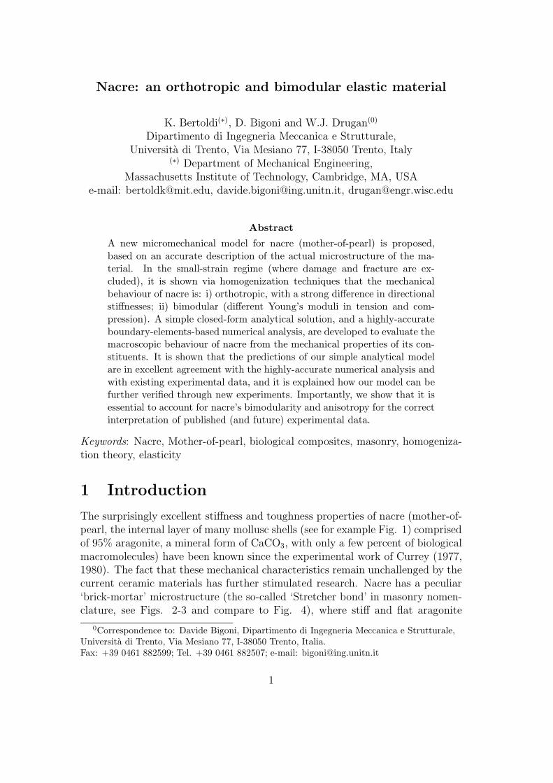
The surprisingly excellent stiffness and toughness properties of nacre (mother-of-pearl, the internal layer of many mollusc shells (see for example Fig. 1) comprisedof 95% aragonite, a mineral form of CaCO3, with only a few percent of biologicalmacromolecules) have been known since the experimental work of Currey (1977,1980). The fact that these mechanical characteristics remain unchallenged by thecurrent ceramic materials has further stimulated research. Nacre has a peculiar‘brick-mortar’ microstructure (the so-called ‘Stretcher bond’ in masonry nomen-clature, see Figs. 2-3 and compare to Fig. 4), where stiff and flat aragonite
0Correspondence to: Davide Bigoni, Dipartimento di Ingegneria Meccanica e Strutturale,Universita di Trento, Via Mesiano 77, I-38050 Trento, Italia.Fax: +39 0461 882599; Tel. +39 0461 882507; e-mail: [email protected]
1
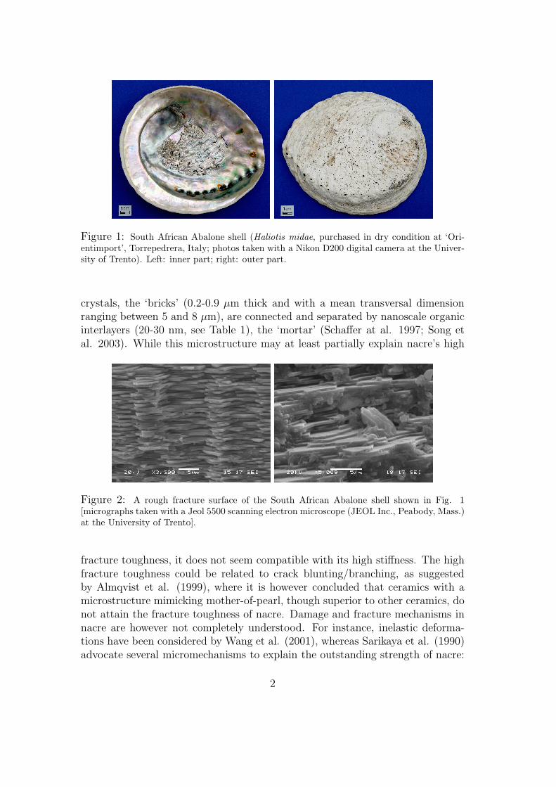
Figure 1: South African Abalone shell (Haliotis midae, purchased in dry condition at ‘Ori-entimport’, Torrepedrera, Italy; photos taken with a Nikon D200 digital camera at the Univer-sity of Trento). Left: inner part; right: outer part.
crystals, the ‘bricks’ (0.2-0.9 µm thick and with a mean transversal dimensionranging between 5 and 8 µm), are connected and separated by nanoscale organicinterlayers (20-30 nm, see Table 1), the ‘mortar’ (Schaffer at al. 1997; Song etal. 2003). While this microstructure may at least partially explain nacre’s high
Figure 2: A rough fracture surface of the South African Abalone shell shown in Fig. 1[micrographs taken with a Jeol 5500 scanning electron microscope (JEOL Inc., Peabody, Mass.)at the University of Trento].
fracture toughness, it does not seem compatible with its high stiffness. The highfracture toughness could be related to crack blunting/branching, as suggestedby Almqvist et al. (1999), where it is however concluded that ceramics with amicrostructure mimicking mother-of-pearl, though superior to other ceramics, donot attain the fracture toughness of nacre. Damage and fracture mechanisms innacre are however not completely understood. For instance, inelastic deforma-tions have been considered by Wang et al. (2001), whereas Sarikaya et al. (1990)advocate several micromechanisms to explain the outstanding strength of nacre:
2
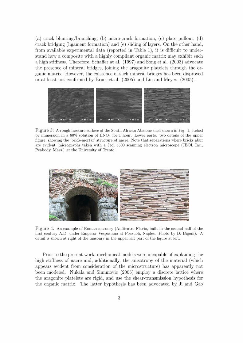
(a) crack blunting/branching, (b) micro-crack formation, (c) plate pullout, (d)crack bridging (ligament formation) and (e) sliding of layers. On the other hand,from available experimental data (reported in Table 1), it is difficult to under-stand how a composite with a highly compliant organic matrix may exhibit sucha high stiffness. Therefore, Schaffer at al. (1997) and Song et al. (2003) advocatethe presence of mineral bridges, joining the aragonite platelets through the or-ganic matrix. However, the existence of such mineral bridges has been disprovedor at least not confirmed by Bruet et al. (2005) and Lin and Meyers (2005).
Figure 3: A rough fracture surface of the South African Abalone shell shown in Fig. 1, etchedby immersion in a 60% solution of HNO3 for 1 hour. Lower parts: two details of the upperfigure, showing the ‘brick-mortar’ structure of nacre. Note that separations where bricks abutare evident [micrographs taken with a Jeol 5500 scanning electron microscope (JEOL Inc.,Peabody, Mass.) at the University of Trento].
Figure 4: An example of Roman masonry (Anfiteatro Flavio, built in the second half of thefirst century A.D. under Emperor Vespasiano at Pozzuoli, Naples. Photo by D. Bigoni). Adetail is shown at right of the masonry in the upper left part of the figure at left.
Prior to the present work, mechanical models were incapable of explaining thehigh stiffness of nacre and, additionally, the anisotropy of the material (whichappears evident from consideration of the microstructure) has apparently notbeen modeled. Nukala and Simunovic (2005) employ a discrete lattice wherethe aragonite platelets are rigid, and use the shear-transmission hypothesis forthe organic matrix. The latter hypothesis has been advocated by Ji and Gao
3
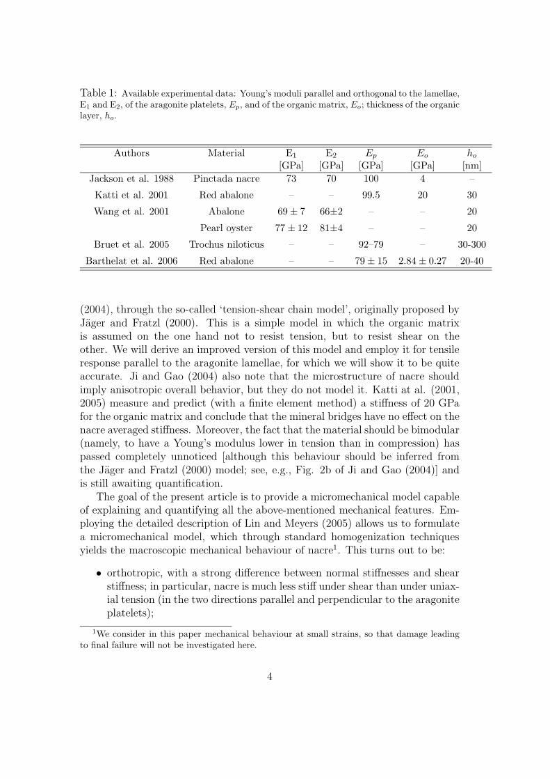
Table 1: Available experimental data: Young’s moduli parallel and orthogonal to the lamellae,E1 and E2, of the aragonite platelets, Ep, and of the organic matrix, Eo; thickness of the organiclayer, ho.
Authors Material E1 E2 Ep Eo ho
[GPa] [GPa] [GPa] [GPa] [nm]
Jackson et al. 1988 Pinctada nacre 73 70 100 4 –
Katti et al. 2001 Red abalone – – 99.5 20 30
Wang et al. 2001 Abalone 69 ± 7 66±2 – – 20
Pearl oyster 77 ± 12 81±4 – – 20
Bruet et al. 2005 Trochus niloticus – – 92–79 – 30-300
Barthelat et al. 2006 Red abalone – – 79 ± 15 2.84 ± 0.27 20-40
(2004), through the so-called ‘tension-shear chain model’, originally proposed byJager and Fratzl (2000). This is a simple model in which the organic matrixis assumed on the one hand not to resist tension, but to resist shear on theother. We will derive an improved version of this model and employ it for tensileresponse parallel to the aragonite lamellae, for which we will show it to be quiteaccurate. Ji and Gao (2004) also note that the microstructure of nacre shouldimply anisotropic overall behavior, but they do not model it. Katti at al. (2001,2005) measure and predict (with a finite element method) a stiffness of 20 GPafor the organic matrix and conclude that the mineral bridges have no effect on thenacre averaged stiffness. Moreover, the fact that the material should be bimodular(namely, to have a Young’s modulus lower in tension than in compression) haspassed completely unnoticed [although this behaviour should be inferred fromthe Jager and Fratzl (2000) model; see, e.g., Fig. 2b of Ji and Gao (2004)] andis still awaiting quantification.
The goal of the present article is to provide a micromechanical model capableof explaining and quantifying all the above-mentioned mechanical features. Em-ploying the detailed description of Lin and Meyers (2005) allows us to formulatea micromechanical model, which through standard homogenization techniquesyields the macroscopic mechanical behaviour of nacre1. This turns out to be:
• orthotropic, with a strong difference between normal stiffnesses and shearstiffness; in particular, nacre is much less stiff under shear than under uniax-ial tension (in the two directions parallel and perpendicular to the aragoniteplatelets);
1We consider in this paper mechanical behaviour at small strains, so that damage leadingto final failure will not be investigated here.
4
• bimodular, i.e. having a Young’s modulus in tension smaller than in com-pression, in the direction parallel to the lamellae long boundaries.
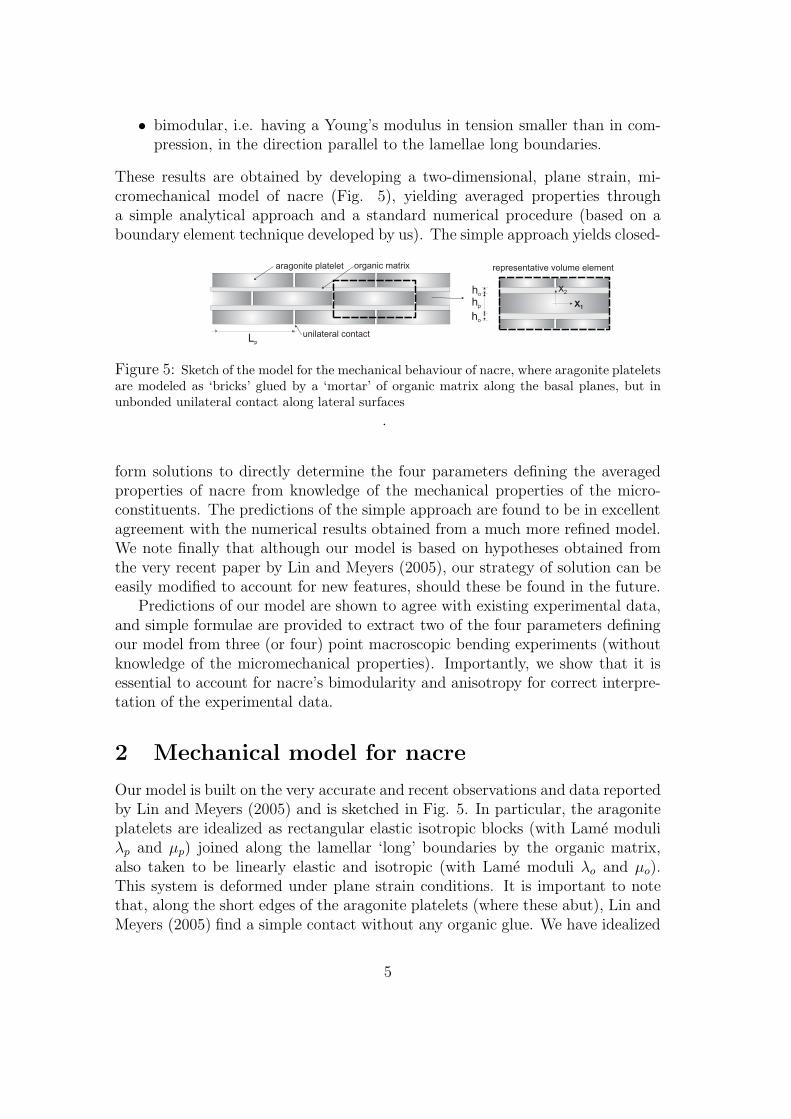
These results are obtained by developing a two-dimensional, plane strain, mi-cromechanical model of nacre (Fig. 5), yielding averaged properties througha simple analytical approach and a standard numerical procedure (based on aboundary element technique developed by us). The simple approach yields closed-
Figure 5: Sketch of the model for the mechanical behaviour of nacre, where aragonite plateletsare modeled as ‘bricks’ glued by a ‘mortar’ of organic matrix along the basal planes, but inunbonded unilateral contact along lateral surfaces
.
form solutions to directly determine the four parameters defining the averagedproperties of nacre from knowledge of the mechanical properties of the micro-constituents. The predictions of the simple approach are found to be in excellentagreement with the numerical results obtained from a much more refined model.We note finally that although our model is based on hypotheses obtained fromthe very recent paper by Lin and Meyers (2005), our strategy of solution can beeasily modified to account for new features, should these be found in the future.
Predictions of our model are shown to agree with existing experimental data,and simple formulae are provided to extract two of the four parameters definingour model from three (or four) point macroscopic bending experiments (withoutknowledge of the micromechanical properties). Importantly, we show that it isessential to account for nacre’s bimodularity and anisotropy for correct interpre-tation of the experimental data.
2 Mechanical model for nacre
Our model is built on the very accurate and recent observations and data reportedby Lin and Meyers (2005) and is sketched in Fig. 5. In particular, the aragoniteplatelets are idealized as rectangular elastic isotropic blocks (with Lame moduliλp and µp) joined along the lamellar ‘long’ boundaries by the organic matrix,also taken to be linearly elastic and isotropic (with Lame moduli λo and µo).This system is deformed under plane strain conditions. It is important to notethat, along the short edges of the aragonite platelets (where these abut), Lin andMeyers (2005) find a simple contact without any organic glue. We have idealized
5
this as a unilateral contact (so that, along the short edges, the platelets behaveas perfectly jointed in compression, whereas these are completely disconnectedunder tension). This idealization is supported by: (i) direct observations by Linand Meyers; (ii) the fact that fracture surfaces do not cross aragonite platelets,which are seen simply to slide one with respect to the other (Sarikaya, 1994;Evans et al. 2001); (iii) the fact that the compressive strength was found to be1.5 times the tensile strength by Menig et al. (2000); (iv) the fact that strainsmuch larger at the tensile than at the compressive surface have been found inthree-point bending by Wang et al. (2001). Clearly, the unilaterality of contactintroduces a nonlinearity in the model. We will see that this can be easily handledat the cost of some approximations.
2.1 Homogenization
The above-introduced model of nacre is periodic and is very similar to typicalmodels for masonry (Pietruszczak and Niu, 1992; Anthoine, 1995; Cecchi andSab, 2002). The goal of homogenization theory (which has been thoroughlydeveloped for periodic elastic media, see for instance Sanchez-Palencia, 1980)is to derive from a microstructure a macroscopic response valid for an effectivecontinuous equivalent medium. To this purpose, a representative volume elementis considered, which, due to the symmetry of our structure, is selected as sketchedin the detail of Fig. 5. The homogenization is performed in the following steps.
• The representative volume element (of volume V and external surface Shaving outward unit normal vector ni) is to be subjected to prescribedmean strain ǫij. To this purpose, the average strain theorem (e.g., Gurtin,1972)
ǫij =1
V
∫
V
ǫij dV =1
2 V
∫
S
(uinj + ujni)dS, (1)
(where ui is the displacement vector, ǫij the related strain) allows us toprescribe the mean strain in terms of an appropriate displacement on theboundary.
• The mean stress σij produced by the application of the mean strain mustbe (numerically or analytically) evaluated on the representative volumeelement. The average stress theorem (e.g., Gurtin, 1972)
σij =1
V
∫
V
σijdV =1
V
∫
S
σiknkxjdS, (2)
(where xj is the position vector and σij the stress tensor) allows us to workin terms of tractions on the boundary.
6
• With the two steps above, an average strain/average stress relation is found,which, when compared to a effective stress/strain relation of the type
σij = Eijhkǫhk, ǫij = E−1
ijhkσhk, (3)
yields the determination of all independent material constants defining thecomposite modulus tensor Eijhk.
Due to the peculiar microstructural geometry, it is well-known that masonryloaded in-plane follows an anisotropic elastic description. Surprisingly, the factthat the microstructure of nacre (which is almost identical to masonry) impliesan anisotropic elastic macroscopic response appears never to have been modelled.For the microstructure of nacre, the effective elastic tensor Eijhk is orthotropic,which in a two-dimensional setting has only the following non-null components
E1111 =E1
1 − ν12ν21, E2222 =
E2
1 − ν12ν21,
E1122 =E1 ν21
1 − ν12ν21, E2211 =
E2 ν12
1 − ν12ν21,
E1212 = E1221 = E2121 = E2112 = G12.
(4)
The inverse tensor E−1
ijhk has the following non-null components
E−1
1111 =1
E1
, E−1
2222 =1
E2
, E−1
1122 = −ν21
E2
, E−1
2211 = −ν12
E1
,
E−1
1212 = E−1
1221 = E−1
2121 = E−1
2112 =1
4G12
,
(5)
where ν12, ν21 are the two plane strain Poisson ratios, and E1, E2, G12 are the twoplane strain elastic tensile moduli and the plane strain shear modulus, subject tothe symmetry condition
ν12
E1
=ν21
E2
, (6)
so that through the homogenization technique we must identify four independentmaterial constants. Note that in the particular case of isotropy, the four constantsreduce to the two plane strain constants
E1 = E2 =E
1 − ν2 , ν21 = ν12 =ν
1 − ν, (7)
in which E and ν are the usual (three-dimensional) elastic constants (Young’smodulus and Poisson’s ratio).
The above four constants can be identified by subjecting the representativevolume element to three independent deformation components (which, employingthe symmetries present, can be reduced to the three boundary displacementsillustrated in Fig. 6), calculating the corresponding averaged stress componentsand comparing to eqn. (3).
7
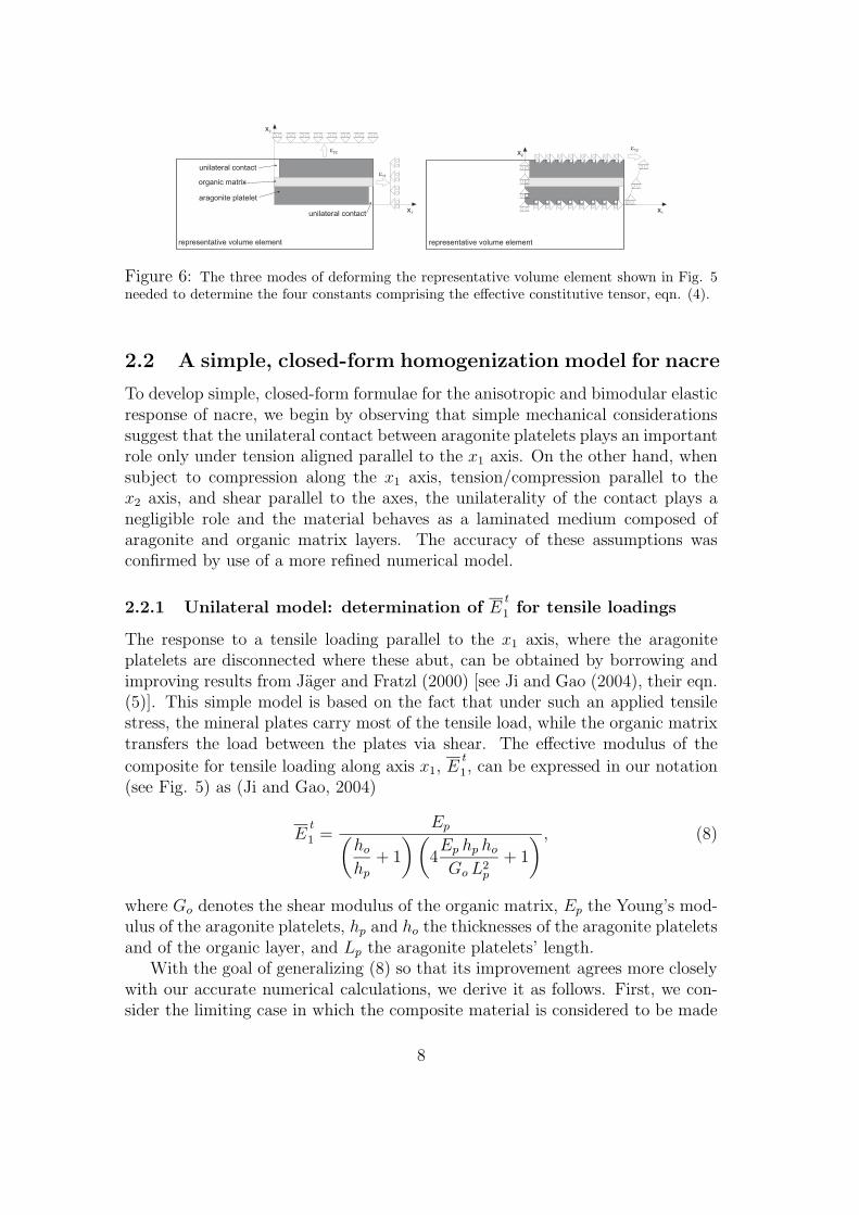
Figure 6: The three modes of deforming the representative volume element shown in Fig. 5needed to determine the four constants comprising the effective constitutive tensor, eqn. (4).
2.2 A simple, closed-form homogenization model for nacre
To develop simple, closed-form formulae for the anisotropic and bimodular elasticresponse of nacre, we begin by observing that simple mechanical considerationssuggest that the unilateral contact between aragonite platelets plays an importantrole only under tension aligned parallel to the x1 axis. On the other hand, whensubject to compression along the x1 axis, tension/compression parallel to thex2 axis, and shear parallel to the axes, the unilaterality of the contact plays anegligible role and the material behaves as a laminated medium composed ofaragonite and organic matrix layers. The accuracy of these assumptions wasconfirmed by use of a more refined numerical model.
2.2.1 Unilateral model: determination of Et
1 for tensile loadings
The response to a tensile loading parallel to the x1 axis, where the aragoniteplatelets are disconnected where these abut, can be obtained by borrowing andimproving results from Jager and Fratzl (2000) [see Ji and Gao (2004), their eqn.(5)]. This simple model is based on the fact that under such an applied tensilestress, the mineral plates carry most of the tensile load, while the organic matrixtransfers the load between the plates via shear. The effective modulus of the
composite for tensile loading along axis x1, Et
1, can be expressed in our notation(see Fig. 5) as (Ji and Gao, 2004)
Et
1 =Ep(
ho
hp+ 1
) (4Ep hp ho
Go L2p
+ 1
) , (8)
where Go denotes the shear modulus of the organic matrix, Ep the Young’s mod-ulus of the aragonite platelets, hp and ho the thicknesses of the aragonite plateletsand of the organic layer, and Lp the aragonite platelets’ length.
With the goal of generalizing (8) so that its improvement agrees more closelywith our accurate numerical calculations, we derive it as follows. First, we con-sider the limiting case in which the composite material is considered to be made
8
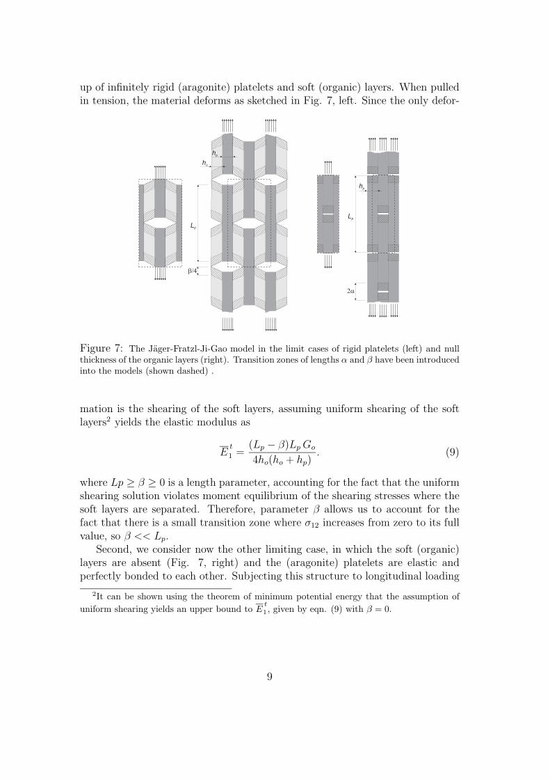
up of infinitely rigid (aragonite) platelets and soft (organic) layers. When pulledin tension, the material deforms as sketched in Fig. 7, left. Since the only defor-
Lp
ho
hp
Lp
hp
2a
b/4
Figure 7: The Jager-Fratzl-Ji-Gao model in the limit cases of rigid platelets (left) and nullthickness of the organic layers (right). Transition zones of lengths α and β have been introducedinto the models (shown dashed) .
mation is the shearing of the soft layers, assuming uniform shearing of the softlayers2 yields the elastic modulus as
Et
1 =(Lp − β)Lp Go
4ho(ho + hp). (9)
where Lp ≥ β ≥ 0 is a length parameter, accounting for the fact that the uniformshearing solution violates moment equilibrium of the shearing stresses where thesoft layers are separated. Therefore, parameter β allows us to account for thefact that there is a small transition zone where σ12 increases from zero to its fullvalue, so β << Lp.
Second, we consider now the other limiting case, in which the soft (organic)layers are absent (Fig. 7, right) and the (aragonite) platelets are elastic andperfectly bonded to each other. Subjecting this structure to longitudinal loading
2It can be shown using the theorem of minimum potential energy that the assumption of
uniform shearing yields an upper bound to Et
1 , given by eqn. (9) with β = 0.
9
and neglecting deformation of the layer near the detachment zones we obtain3
Et
1 =Ep
4 αLp
+ 1, (10)
where the length parameter α (Lp/4 ≥ α ≥ 0) has been introduced. This is simi-lar to the parameter β and permits us to account for the fact that there is a smalltransizion zone, at the unbonded platelet end, in which σ11 increases from zeroto its full value, so α << Lp. When the transition zone length is zero (i.e. α = 0)the elastic modulus is that of the intact material. Clearly the behaviour of theactual composite lies between these limiting cases. Combining therefore the twolimiting cases as springs in series (i.e. summing the compliances) in proportionto the volume fraction of each material, where the platelet volume fraction is
Φ =hp
ho + hp, (11)
(Φ = 1 corresponds to the limiting case shown at Fig. 7 right, while Φ = 0 tothe limiting case shown at Fig. 7 left) we obtain
1
Et
1
=4h2
p(1 − Φ)
Lp(Lp − β)Go Φ2+
4α
Lp
+ 1
ΦEp
. (12)
Eqn. (12) can be rewritten as
Et
1 =Ep(
ho
hp+ 1
)(4
Ep hp ho
GoLp(Lp − β)+
4α
Lp+ 1
) , (13)
which is a generalization of the Jager-Fratzl-Ji-Gao model, in the sense that thismodel is retrieved when α = β = 0.
Since parameter β/Lp is small, we can define a new parameter γ as
γ
Lp=Ep hp ho
Go L2p
4β
Lp+
4α
Lp, (14)
so that a Taylor series expansion of eqn. (13) in β/Lp and then use of eqn. (14)yields
Et
1 =Ep(
ho
hp+ 1
) (4Ep hp ho
Go L2p
+γ
Lp+ 1
) , (15)
again reducing to the Jager-Fratzl-Ji-Gao model, when γ = 0. Eqn. (15) will beshown to yield a more accurate approximation than eqn. (8).
3It can be shown using the theorem of minimum potential energy that the assumption of
uniform longitudinal strain yields an upper bound to Et
1 , given by eqn. (10) with α = 0.
10
2.2.2 Layered model: determination of Ec
1, E2, ν12 and ν21 for com-
pressive loadings
When loaded in compression or under shear, nacre behaves (following our sim-plifying assumptions) as a monolithic laminate material, composed of uniformisotropic laminae of thickness hp and ho (see Fig. 5). Homogenization of thistype of material is standard and can be found for instance in Willis (2003). How-ever, for completeness, we provide a sketch of the approach here. We assumeǫ22 = ǫ12 = 0 and ǫ11 = ǫ11 = constant in all laminae (so that compatibility issatisfied). Uniform σ11 and σ22 are generated, the former different in each lamina(but trivially satisfying equilibrium) and the latter must be required to be equalin each lamina (and equal to the mean value σ22) by equilibrium considerationsat the interface. It follows that in a generic layer (having elastic constants E andν)
σ11 =ǫ11E + σ22ν(1 + ν)
1 − ν2. (16)
Using eqn. (16) in the condition ǫ22 = 0, valid for the unit cell, we obtain
E2211 =σ22
ǫ11=
⟨ν
1 − ν
⟩⟨(1 + ν)(1 − 2ν)
E(1 − ν)
⟩−1
, (17)
where the bracket 〈 〉 is used to denote the mean value of a generic function ψ asfollows
〈ψ(E, ν)〉 =hoψ(Eo, νo) + hpψ(Ep, νp)
ho + hp
. (18)
Using eqn. (17) in eqn. (16) and averaging, we obtain
E1111 =σ11
ǫ11=
⟨E
1 − ν2
⟩+
⟨ν
1 − ν
⟩2 ⟨(1 + ν)(1 − 2ν)
E(1 − ν)
⟩−1
. (19)
Finally, we impose a mean strain whose only non-zero component is ǫ22. Anal-ogously to the previous case, we obtain for a generic layer (defined by E and ν)
σ11 =σ22ν
1 − ν, (20)
so that
E2222 =σ22
ǫ22=
⟨1 − ν − 2ν2
E(1 − ν)
⟩−1
. (21)
Hence, the effective elastic constants Ec
1, E2, ν12 and ν21 can be determined by
11
employing eqn. (4) as:
Ec
1 =Eo ho(1 − ν2
p) + Ep hp(1 − ν2o)
(ho + hp)(1 − ν2p)(1 − ν2
o ),
E2 =EoEp(ho + hp)
[Eo ho(1 − ν2
p) + Ep hp(1 − ν2o )
]
Γ,
ν21 =EoEp(ho + hp)(1 + νp)(1 + νo) [νo ho(1 − νp) + νp hp(1 − νo)]
Γ,
ν12 =νo ho(1 − νp) + νp hp(1 − νo)
(ho + hp)(1 − νp)(1 − νo),
(22)
where
Γ = ho hp
[E2
p(1 + νo)2(1 − 2νo) + E2
o(1 + νp)2(1 − 2νp) + 2EoEpνoνp(1 + νp)(1 + νo)
]
+EoEp (h2o + h2
p)(1 − ν2p)(1 − ν2
o ).(23)
2.2.3 Layered model: determination of G12
In order to determine the effective shear modulus of the composite, we consideragain the monolithic layered model considered before and we prescribe a meanstrain ǫ12, requiring σ12 = σ12 in all layers. We obtain
G12 = E1212 =σ12
ǫ12=
1
2
⟨1 + ν
E
⟩−1
, (24)
which becomes
G12 =EoEp(ho + hp)
2 [Ep ho(1 + νo) + Eo hp(1 + νp)]. (25)
Formulae (15), (22), and (25) represent the results of our simple homoge-nization approach; these allow a relation between the micromechanical geome-try and properties and the macroscopic, effective behaviour. As a simple check,note that in the special case Eo = Ep = E and νo = νp = ν, eqns. (22) and(25) yield the correct plane strain isotropic constants: E1 = E2 = E/(1 − ν2),ν12 = ν21 = ν/(1 − ν2), and G12 = E/(2 + 2ν).
It should be noted that in order to use the bimodular model that we proposefor stress states different from uniaxial tension or compression, a criterion fordividing strain space into compression and tension subdomains is needed (some-thing analogous to a yield criterion in strain space plasticity), and continuity ofthe stress/strain law should be enforced (see Curnier et al. 1995 for details). Wedo not pursue this subject further here.
12
2.3 Results from a boundary elements-based numerical
technique
Since via the averaging theorems we can work with displacements and tractions onthe surface of the representative volume element, a numerical boundary elementtechnique seems to be particularly appropriate. We have used a general-purposeFortran 90 code for two-dimensional analysis4. In the code, linear (constant)shape functions for the displacements (tractions) at the boundary are assumed,and the material has been taken to be linear elastic, with Lame moduli λ and µ.The unit cell (see Fig. 5) has been discretized along boundaries parallel to the x1
axis employing 50 elements and along the boundaries parallel to the x2 axis using20 elements for the aragonite platelets and 10 elements for the organic matrixlayer. Following Sarikaya el al. (1990), the thickness of the aragonite plates andof the interlayers have been chosen respectively as hp = 0.5 µm and ho = 20 nm,while the length of the plates has been selected as Lp = 5 µm.
In the numerical analyses, both the aragonite plates and the organic inter-phase have been modelled as linear elastic materials, having Young’s moduliEp = 100 GPa and Eo ranging between 0 and 10 GPa to cover the range of valuesexperimentally measured (see Table 1)(the Poisson ratio has been taken equal to0.33 for both materials). The unilaterality of the contact has been accounted forby using a small gap where platelets abut and confirming that this gap opensunder tensile applied loading, while no gap was used under compressive loading.
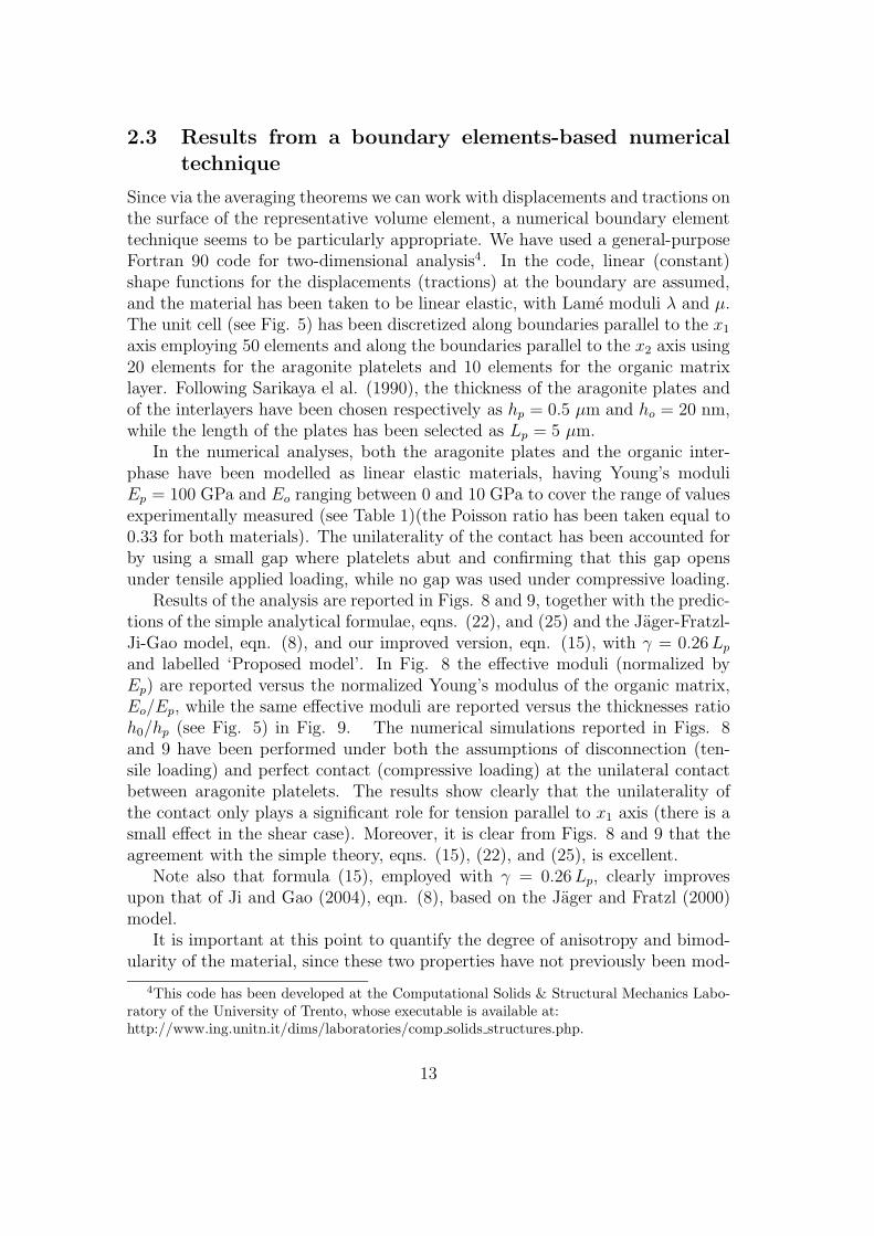
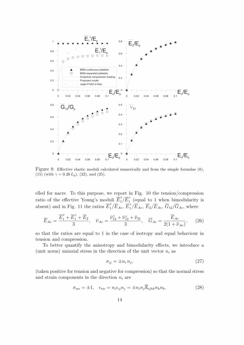
Results of the analysis are reported in Figs. 8 and 9, together with the predic-tions of the simple analytical formulae, eqns. (22), and (25) and the Jager-Fratzl-Ji-Gao model, eqn. (8), and our improved version, eqn. (15), with γ = 0.26Lp
and labelled ‘Proposed model’. In Fig. 8 the effective moduli (normalized byEp) are reported versus the normalized Young’s modulus of the organic matrix,Eo/Ep, while the same effective moduli are reported versus the thicknesses ratioh0/hp (see Fig. 5) in Fig. 9. The numerical simulations reported in Figs. 8and 9 have been performed under both the assumptions of disconnection (ten-sile loading) and perfect contact (compressive loading) at the unilateral contactbetween aragonite platelets. The results show clearly that the unilaterality ofthe contact only plays a significant role for tension parallel to x1 axis (there is asmall effect in the shear case). Moreover, it is clear from Figs. 8 and 9 that theagreement with the simple theory, eqns. (15), (22), and (25), is excellent.
Note also that formula (15), employed with γ = 0.26Lp, clearly improvesupon that of Ji and Gao (2004), eqn. (8), based on the Jager and Fratzl (2000)model.
It is important at this point to quantify the degree of anisotropy and bimod-ularity of the material, since these two properties have not previously been mod-
4This code has been developed at the Computational Solids & Structural Mechanics Labo-ratory of the University of Trento, whose executable is available at:http://www.ing.unitn.it/dims/laboratories/comp solids structures.php.
13
E /E1 p
c
E /E2 p
G /G12 p
E /Eo p E /Eo p
E /Eo p0 0.02 0.04 0.06 0.08 0.1
0
0.1
0.2
0.3
0.4
0.5
E /Eo p
n21
E /E1 p
t
0 0.02 0.04 0.06 0.08 0.1
0
0.2
0.4
0.6
0.8
0 0.02 0.04 0.06 0.08 0.1
0
0.2
0.4
0.6
0.8
0 0.02 0.04 0.06 0.08 0.1
0
0.2
0.4
0.6
0.8
1
BEM continuous platelets
BEM separated platelets
Analytical compression loading
Proposed model
Jager-Fratzl-Ji-Gao
Figure 8: Effective elastic moduli calculated numerically and from the simple formulae (8),(15) (with γ = 0.26 Lp), (22), and (25).
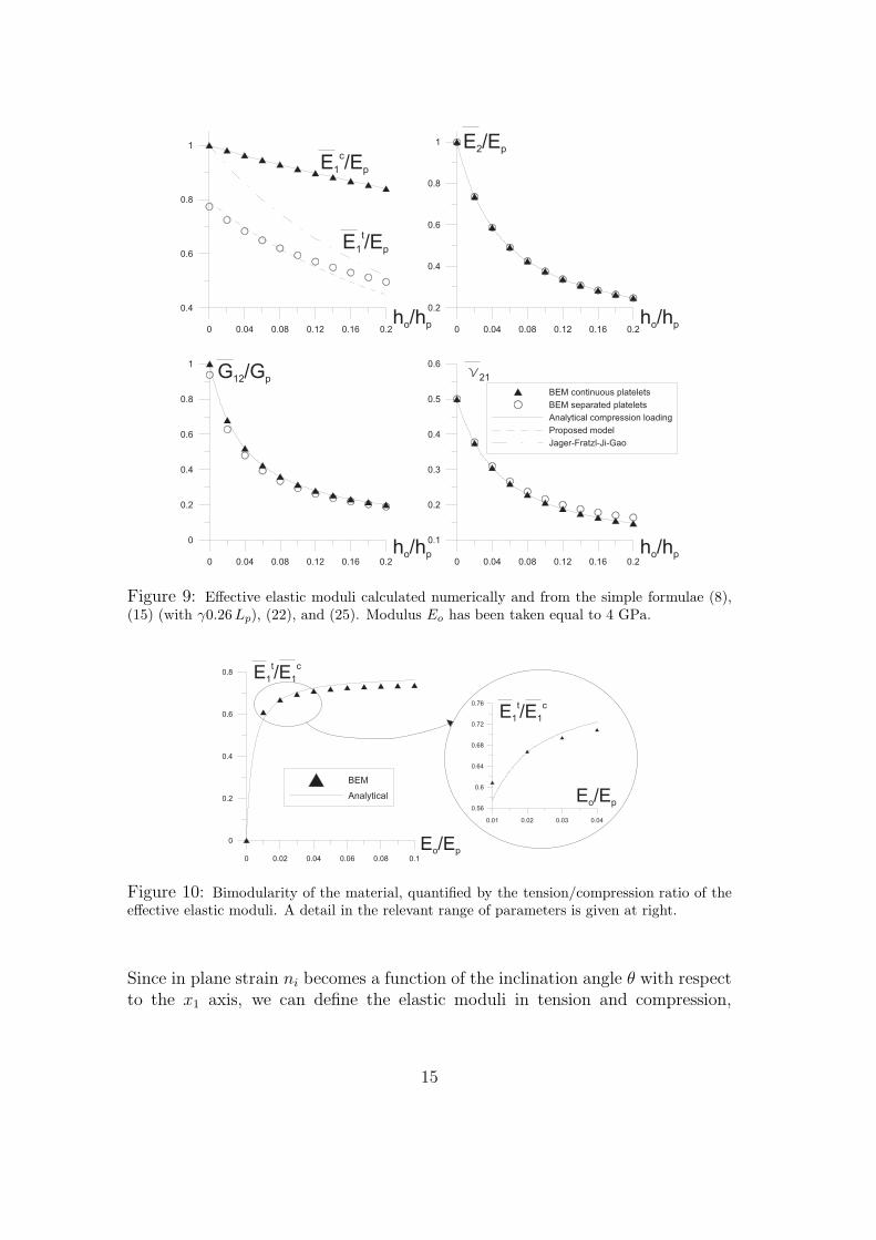
elled for nacre. To this purpose, we report in Fig. 10 the tension/compression
ratio of the effective Young’s moduli Et
1/Ec
1 (equal to 1 when bimodularity is
absent) and in Fig. 11 the ratios Et
1/EAv, Ec
1/EAv, E2/EAv, G12/GAv, where
EAv =E
t
1 + Ec
1 + E2
3, νAv =
ν t12 + ν c
12 + ν21
3, GAv =
EAv
2(1 + νAv), (26)
so that the ratios are equal to 1 in the case of isotropy and equal behaviour intension and compression.
To better quantify the anisotropy and bimodularity effects, we introduce a(unit norm) uniaxial stress in the direction of the unit vector ni as
σij = ±ni nj , (27)
(taken positive for tension and negative for compression) so that the normal stressand strain components in the direction ni are
σnn = ±1, ǫnn = niǫijnj = ±ninjEijhknhnk. (28)
14
E /E1 p
cE /E2 p
G /G12 p
h /o ph
h /o ph
h /o ph
h /o ph
n21
E /E1 p
t
0 0.04 0.08 0.12 0.16 0.2
0
0.2
0.4
0.6
0.8
1
0 0.04 0.08 0.12 0.16 0.2
0.1
0.2
0.3
0.4
0.5
0.6
0 0.04 0.08 0.12 0.16 0.2
0.2
0.4
0.6
0.8
1
BEM continuous platelets
BEM separated platelets
Analytical compression loading
Proposed model
Jager-Fratzl-Ji-Gao
0 0.04 0.08 0.12 0.16 0.2
0.4
0.6
0.8
1
Figure 9: Effective elastic moduli calculated numerically and from the simple formulae (8),(15) (with γ0.26 Lp), (22), and (25). Modulus Eo has been taken equal to 4 GPa.
0 0.02 0.04 0.06 0.08 0.1
0
0.2
0.4
0.6
0.8
E /Eo p
E /E1 1
t c
BEM
Analytical E /Eo p
E /E1 1
t c
0.01 0.02 0.03 0.04
0.56
0.6
0.64
0.68
0.72
0.76
Figure 10: Bimodularity of the material, quantified by the tension/compression ratio of theeffective elastic moduli. A detail in the relevant range of parameters is given at right.
Since in plane strain ni becomes a function of the inclination angle θ with respectto the x1 axis, we can define the elastic moduli in tension and compression,
15
G /G12 Av
E /Eo p E /Eo p
BEM
Analytical
E /E1 Av
c
E /E2 Av
E /E1 Av
t
0 0.02 0.04 0.06 0.08 0.1
0
0.2
0.4
0.6
0.8
1
0 0.02 0.04 0.06 0.08 0.1
0
1
2
3
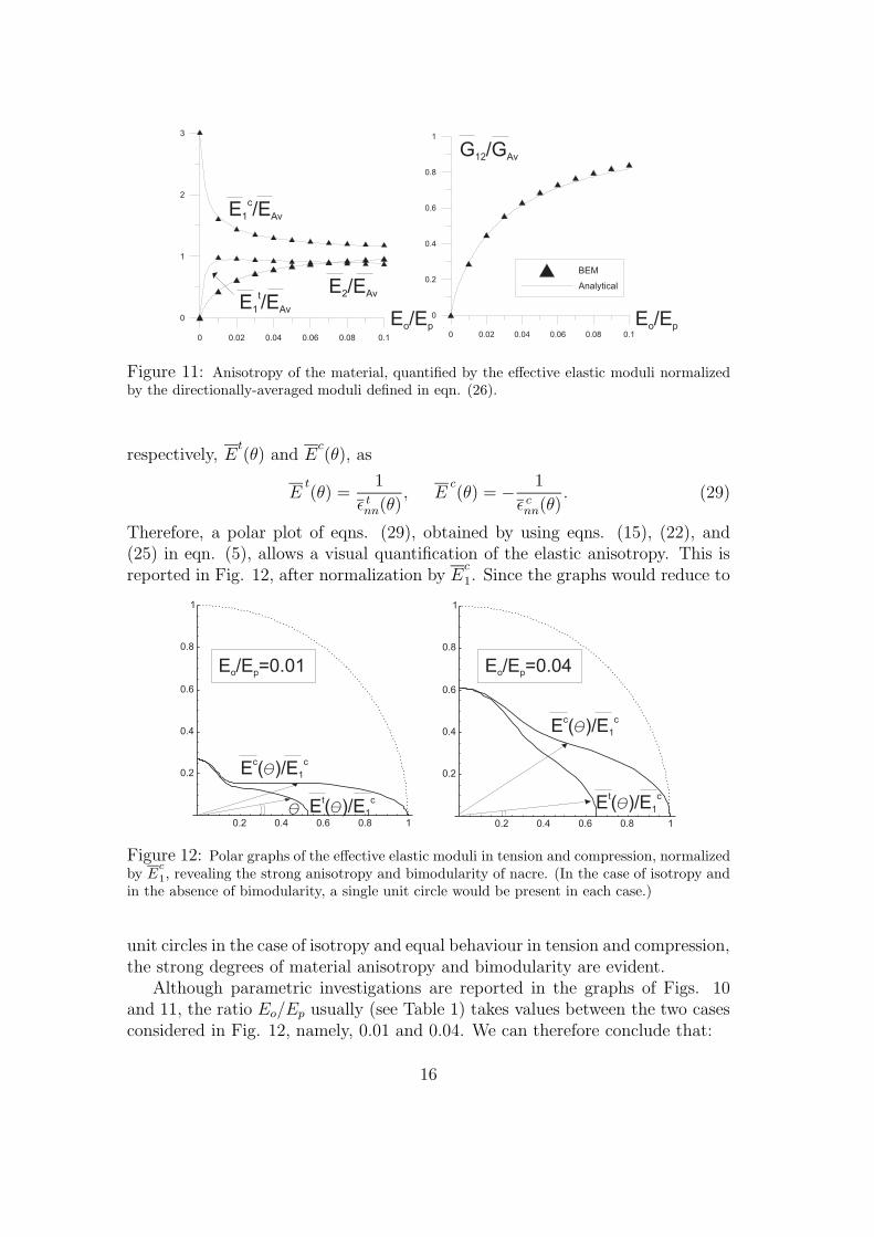
Figure 11: Anisotropy of the material, quantified by the effective elastic moduli normalizedby the directionally-averaged moduli defined in eqn. (26).
respectively, Et(θ) and E
c(θ), as
Et(θ) =
1
ǫ tnn(θ)
, Ec(θ) = − 1
ǫ cnn(θ)
. (29)
Therefore, a polar plot of eqns. (29), obtained by using eqns. (15), (22), and(25) in eqn. (5), allows a visual quantification of the elastic anisotropy. This isreported in Fig. 12, after normalization by E
c
1. Since the graphs would reduce to
0.2 0.4 0.6 0.8 1
0.2
0.4
0.6
0.8
1
0.2 0.4 0.6 0.8 1
0.2
0.4
0.6
0.8
E /E =0.04o p
E ( )/c
q E1
c
E( )/tq E1
c
q
E /E =0.01o p
E ( )/c
q E1
c
E( )/tq E1
c
Figure 12: Polar graphs of the effective elastic moduli in tension and compression, normalizedby E
c
1, revealing the strong anisotropy and bimodularity of nacre. (In the case of isotropy andin the absence of bimodularity, a single unit circle would be present in each case.)
unit circles in the case of isotropy and equal behaviour in tension and compression,the strong degrees of material anisotropy and bimodularity are evident.
Although parametric investigations are reported in the graphs of Figs. 10and 11, the ratio Eo/Ep usually (see Table 1) takes values between the two casesconsidered in Fig. 12, namely, 0.01 and 0.04. We can therefore conclude that:
16
• the ratio Et
1/Ec
1 ranges between 0.5 and 0.8, showing that bimodularity isan important effect (a fact previously not understood, and therefore nottested);
• both the ratios Ec
1/EAv and E2/EAv lie near 1, (a fact consistent withexperimental results by Jackson et al. 1988 and Wang et al. 2001);
• the ratioG12/GAv ranges between 0.3 and 0.6, showing a strong difference indegree of anisotropy between the shear and Young’s moduli (a fact noticedalso by Jackson et al. 1988).
3 Comparison with experimental data
To compare the predictions of our model with available experimental data, werefer to Table 1, where data taken from the literature are reported.
Before discussing the model’s predictions, we note that the experimental re-sults reported in Table 1 have been mainly determined via three-point bendingtests. These tests are usually interpreted by employing the linear theory of uni-modular isotropic elasticity, but, in light of our findings, these should instead beinterpreted with formulae valid for bimodular, orthotropic elasticity. These arederived in Appendix A, and summarized here:
• For three-point bending of a beam of span l, thickness h and loaded by aforce per unit depth P , the deflected shape of the neutral axis is
u2(x1) =(1 +
√c)2Px1(3l
2 − 4x21)
16Et
1h3
+3Px1
5G12h, x1 ∈ [0, l/2], (30)
(where c = Et
1/Ec
1 , and c = 1 corresponds to equal behaviour in tensionand compression) so that the mid-span vertical displacement δ divided bythe applied load P is
δ
P=
(1 +√c)2
16Et
1
(l
h
)3
+3
10G12
l
h. (31)
• For four-point bending of a beam of span l, thickness h and loaded at x1 = l0by a force per unit depth P (neglecting shear deformation), the deflectedshape of the neutral axis is
u2(x1) =(1 +
√c)2P x1
2Et
1 h3
(3 l l0 − 3 l20 − x2
1
), x1 ∈ [0, l0]
u2(x1) =(1 +
√c)2P l0
2Et
1 h3
(3 x1(l − x1) − l20
), x1 ∈ [l0, l/2]
(32)
17
so that the vertical displacement δ at x1 = l0, i.e. where the vertical forceP is applied, is
δ
P=
(1 +√c)2
8Et
1
l0(3l2 − 4l20)
h3. (33)
It is clear from eqns. (31) and (33) that using three or four point bendingtests we can only identify two parameters
(1 +√c)2
Et
1
, and G12,
so that the full exploration of bimodularity and orthotropy requires use of at leastone additional test (such as for instance a direct tension or compression test or,perhaps, nanoindentation).
Moreover, the effect of low shear modulus G12 only plays a role for sufficientlyhigh values of h/l. The experiments performed by Jackson et al. (1988) refer tovery low values of h/l, so that shear deformation should be negligible. However,bimodularity should play an important role in those experiments, and thereforethe Young’s modulus obtained by Jackson et al. must be corrected before com-paring it to the prediction of our model. This correction can be obtained byconsidering eqn. (31) without shear deformation, with c = 1, as used by Jacksonet al., and with c < 1, as found by us. The result is the relationship
E1 =4E
t
1
(1 +√c)2
, (34)
where E1 is the Young’s modulus in the direction of the x1 axis, assuming equalbehaviour in tension and compression. It should be noted that there is no dif-ference between the Young’s modulus in the direction of the x2 axis found by usand by Jackson et al., since bimodularity does not play a role in that case.
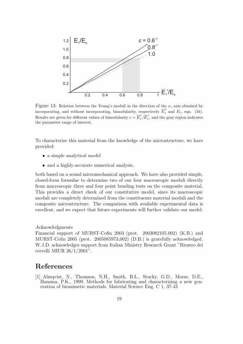
Eqn. (34) is plotted in Fig. 13, for the three values c = {1, 0.8, 0.6}. The greyzone denotes the parameter range of interest. We observe that the correction issignificant and that we find values of E1/Ep in the range 0.7–0.8, in agreementwith the experimental data reported in Table 1.
4 Conclusions
Within the framework of the small strain behaviour of nacre (mother-of-pearl),we have accounted for the first time for the facts that the material response is:
• orthotropic, with low shear stiffness;
• bimodular (lower Young’s modulus in tension than in compression).
18
0.2 0.4 0.6 0.8 1
0.2
0.4
0.6
0.8
1.0
1.2
1.0
0.8
E /E1 p
t
E /Ep1c = 0.6
Figure 13: Relation between the Young’s moduli in the direction of the x1 axis obtained by
incorporating, and without incorporating, bimodularity, respectively Et
1and E1, eqn. (34).
Results are given for different values of bimodularity c = Et
1/Ec
1 , and the gray region indicatesthe parameter range of interest.
To characterize this material from the knowledge of the microstructure, we haveprovided:
• a simple analytical model
• and a highly-accurate numerical analysis,
both based on a sound micromechanical approach. We have also provided simple,closed-form formulae to determine two of our four macroscopic moduli directlyfrom macroscopic three and four point bending tests on the composite material.This provides a direct check of our constitutive model, since its macroscopicmoduli are completely determined from the constituents material moduli and thecomposite microstructure. The comparison with available experimental data isexcellent, and we expect that future experiments will further validate our model.
Acknowledgments
Financial support of MURST-Cofin 2003 (prot. 2003082105 002) (K.B.) andMURST-Cofin 2005 (prot. 2005085973 002) (D.B.) is gratefully acknowledged.W.J.D. acknowledges support from Italian Ministry Research Grant ”Rientro deicervelli MIUR 26/1/2001”.
References
[1] Almqvist, N., Thomson, N.H., Smith, B.L., Stucky, G.D., Morse, D.E.,Hansma, P.K., 1999. Methods for fabricating and characterizing a new gen-eration of biomimetic materials. Material Science Eng. C 1, 37-43
19
[2] Anthoine, A., 1995. Derivation of the in-plane elastic characteristics of ma-sonry through homogenization theory. Int. J. Solids Structures 32, 137-163.
[3] Bruet, B.J.F., Qi, H.J., Boyce, M.C., Panas, R., Tai, K., Frick, L., Ortiz, C.2005. Nanoscale morphology and indentation of individual nacre tablets fromthe gastropod mollusc Trochus niloticus. J. Mat. Res. 20, 2400-2419.
[4] Barthelat, F., Li, C.M., Comi, C., Espinosa, H.D., 2006. Mechanical prop-erties of nacre constituents and their impact on mechanical performance. J.Mater. Res. 21, 1977-1986
[5] Cecchi, A., Sab, K. 2002. A multi-parameter homogenization study for mod-eling elastic masonry Eur. J. Mechanics-A/Solids 21, 249-268.
[6] Curnier, A., He, Q.-C., Zysset, P., 1995. Conewise linear elastic materials. J.Elasticity 37, 1-38.
[7] Currey, J.D., 1977. Mechanical properties of Mother of pearls in tension.Proc. R. Soc. Lond. 196, 443-463.
[8] Currey, J.D., 1980. The mechanical properties of biological materials. 34thSymposium of the Society for Experimental Biology, Cambridge UniversityPress.
[9] Evans, A.G., Suo, Z., Wang, R.Z., Aksay, I.A., He, M.Y., Hutchinson, J.W.,2001. Model for the robust mechanical behavior of nacre. J. Mat. Res. 16,2475-2484.
[10] Jackson, A.P., Vincent, J.F.V., Turner, R.M., 1988. The Mechanical Designof Nacre. Proc. R. Soc. Lond. 234, 415-440.
[11] Jager , I., Fratzl, P., 2000. Mineralized collagen fibrils: A mechanical modelwith staggered arrangemen of mineral particles. Biophysical Journal 79, 1737-1746.
[12] Ji, B., Gao, H.J., 2004. Mechanical properties of nanostructures of biologicalmaterial. J. Mech. Phys. Solids 52, 1963-1990.
[13] Gurtin, M.E., 1972. The linear theory of Elasticity. In Flugge, S., ed., En-cyclopedia of Physics VIa/2. Berlin, Springer. 1-295.
[14] Katti, D.R., Katti, K.S., Sopp, J.M., Sarikaya, M. 2001. 3D finite ele-ment modelling of mechanical response in nacre-based hybrid nanocomposites.Comp. Theo. Poly. Sci. 11, 397-404.
[15] Katti, D.R., Katti, K.S., Tang, J., Pradhan, S., Sarikaya, M. 2005. Modelingmechanical response in a laminated biocomposite. Part II: Nonlinear responsesand nuances of nanostructures. J. Mat. Sci. 40, 1749-1755.
[16] Lin, A., Meyers, M.A., 2005. Growth and structure in abalone shell. Mat.Sci. Eng. A 390, 27-41.
[17] Menig, R., Meyers, M.H., Meyers, M.A., Vecchio, K.S., 2000. Quasi-staticand dynamic mechanical response of haliotis rufescens (abalone) shells. ActaMater. 48, 2383-2398.
20
[18] Nukala, P.K.V.V., Simunovic, S., 2005. Statistical physics models for nacrefracture simulation. Physical Review E. 72, Art. No. 041919.
[19] Pietruszczak, S., Niu, X., 1992. A mathematical description of macroscopicbehaviour of brick masonry. Int. J. Solids Structures 29, 531-546.
[20] Sanchez-Palencia, E., 1980. Non homogeneous media and vibration theory.Lecture Notes in Physics, Vol. 127 Springer Verlag, Berlin.
[21] Sarikaya, M., 1994. An introduction to biomimetics - a structural viewpointMicroscopy Res. Tech. 27, 360-375.
[22] Sarikaya, M., Gunnison, K.E., Yasrebi, M., Aksay, I.A., 1990. Mechanicalproperties-microstructural relationship in abalone shell. Mat. Res. Symp. Proc.174, 109-116.
[23] Schaffer, T.E., Ionescu-Zanetti, C., Proksch, R., Fritz, M., Walters, D.A.,Almqvist, N., Zaremba, C.M., Belcher, A.M., Smith, B.L., Galen, D.S., Morse,D.E., Hansma, P.K, 1997. Does Abalone nacre form by heteroepitaxial nucle-ation or by growth trough mineral bridges?. Chem. Mater. 9, 1731-1740.
[24] Song, F., Soh, A.K., Bai, Y.L., 2003. Structural and mechanical propertiesof the organic layers of nacre. Biomaterials 24, 3623-3631.
[25] Timoshenko, S.P., 1953. History of strength of materials. McGraw-Hill BookCompany Inc. N.Y.
[26] Wang, R.Z., Suo, Z., Evans, A.G., Yao, N., Aksay, I.A., 2001. Deformationmechanisms in nacre. J. Mater. Res. 16, 2485-93.
[27] Willis, J.R., 2003. Mechanics of composites, Unpublished lecture notes, Uni-versity of Cambridge.
Appendix A: Bending of an orthotropic, bimodular beam deformed
in plane strain
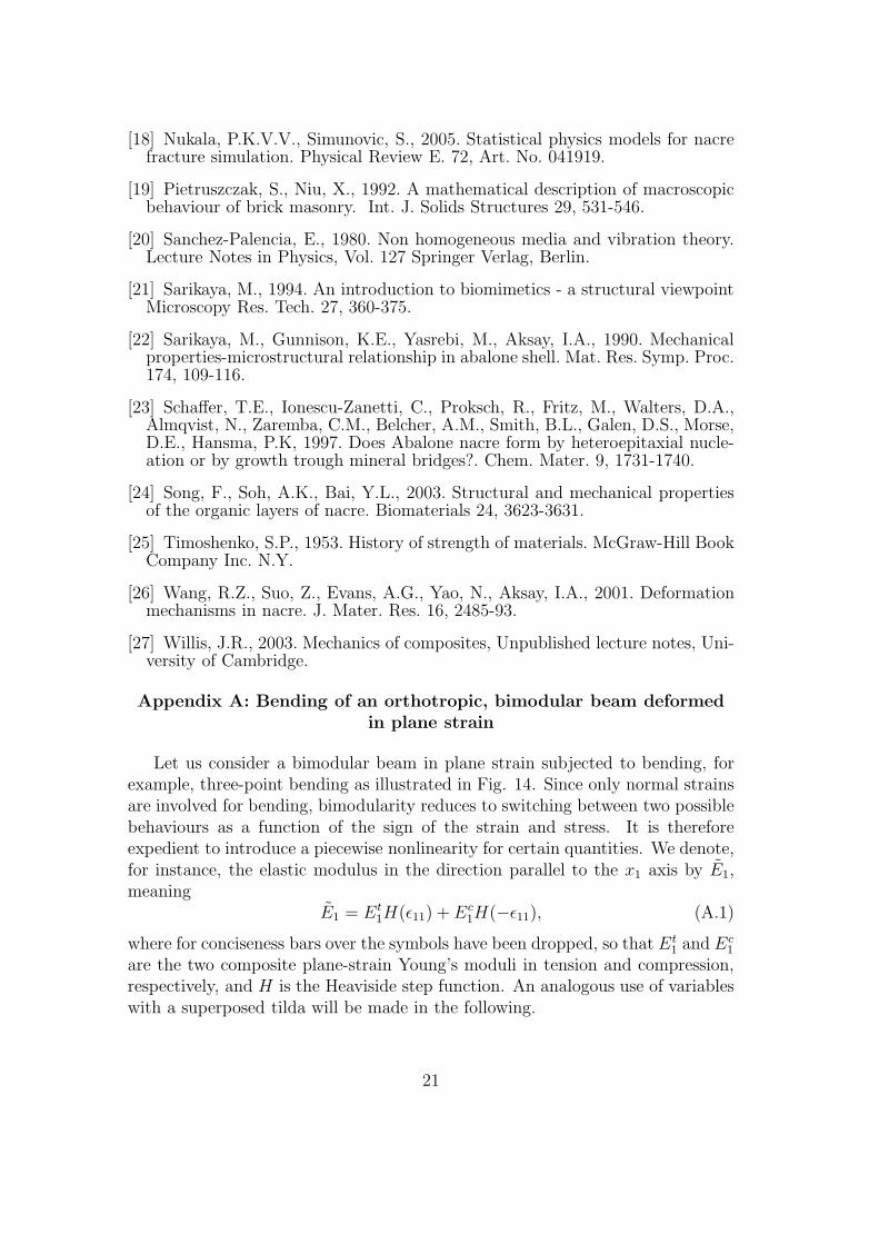
Let us consider a bimodular beam in plane strain subjected to bending, forexample, three-point bending as illustrated in Fig. 14. Since only normal strainsare involved for bending, bimodularity reduces to switching between two possiblebehaviours as a function of the sign of the strain and stress. It is thereforeexpedient to introduce a piecewise nonlinearity for certain quantities. We denote,for instance, the elastic modulus in the direction parallel to the x1 axis by E1,meaning
E1 = Et1H(ǫ11) + Ec
1H(−ǫ11), (A.1)
where for conciseness bars over the symbols have been dropped, so that Et1 and Ec
1
are the two composite plane-strain Young’s moduli in tension and compression,respectively, and H is the Heaviside step function. An analogous use of variableswith a superposed tilda will be made in the following.
21
h
Pe11<0
x1
x2
s11 1=Ece11
l
e11 0> s11 1=Ete11
Figure 14: Bending of a bimodular beam.
For plane strain bending, it is assumed that the resultant force in the directionof the x1 axis is null ∫ h/2
−h/2
ǫ11(x2)E1dx2 = 0, (A.2)
and that the applied bending moment per unit thickness M is given by
M =
∫ h/2
−h/2
ǫ11(x2)E1x2dx2, (A.3)
where h is the height of the beam. The strain component ǫ11 is assumed to varylinearly along the direction of the x2 axis, so that from eqns. (A.2) and (A.3) weobtain
ǫ11(x2) =3M [h(1 − c) + 2x2(1 +
√c)2]
2Et1h
3, (A.4)
where c = Et1/E
c1. Therefore, the neutral axis is defined by
x2 =h
2
√c− 1√c+ 1
, (A.5)
so that its position is independent of the applied moment. From the bimodular,two-dimensional stress-strain relationship for an orthotropic material, we find
ǫ11 =σ11
E1
, and ǫ22 = −σ11ν12
E1
. (A.6)
Integration provides the displacement field in the form
u1(x1, x2) = ǫ11(x2)x1,
u2(x1, x2) = −3Mzx2[h(1 − c) + x2(1 +√c)2]
2Et1h
3ν12 + v0(x1).
(A.7)
22
where ǫ11(x2) is given by eqn. (A.4). Since the shear strains must be zero, wefind that
v0(x1) = −3(1 +√c)2Mz
Et1h
3
x21
2+ v1(x1), (A.8)
and, in order to have continuity of the displacement at the neutral axis, we get
v1(x1) =3Mz(−1 +
√c)2(νt
12 − νc12)
8cEc1h
H(−ǫ11(x2)). (A.9)
The displacement components of the neutral axis are given by
u1 = 0 u2 =3M [−4(1 +
√c)2x2
1 + (−1 +√c)2h2νt
12]
8Et1h
3, (A.10)
so that the elastica is given by
∂2 u2
∂ x21
= −3M(1 +√c)2
Et1h
3. (A.11)
For a simply-supported beam of span l loaded by two concentrated loads Pper unit thickness (plane-strain four-point bending), integration of the elasticayields (neglecting shear deformation) eqn. (32) and thus eqn. (33).
For a simply-supported beam of span l loaded by a central concentrated loadP per unit thickness (plane-strain three point bending), integration of the elasticayields (neglecting shear deformation)
u2(x1) =(1 +
√c)2Px1(3l
2 − 4x21)
16Et1h
3. (A.12)
Since our material has a low shear modulus G12, it may be important toevaluate the contribution to the elastica of shear deformability. To this purpose,we follow Jourawski’s analysis (which by the way originated to take into accountthe high compliance of wood under shearing, Timoshenko, 1953), thus finding forthe mean shear stresses in a bimodular (plane strain) beam
σ12(x2) =3T
8 h3 c
{4 h2 c−
[(√c− 1)h− 2(
√c+ 1)x2
]2H(ǫ11(x2))−
c (√c+ 1)(h− 2 x2) [(
√c− 3)h− 2(
√c + 1)x2]H(−ǫ11(x2))} ,
(A.13)where T is the shear force per unit thickness.
Equating the strain energies in the beam calculated from external load andfrom internal stresses (or, in other words, using Clapeyron’s theorem) we obtainfor the shear deformability
∂ u2
∂ x1
=6T
5 hG12
, (A.14)
23
so that (within the usual approximations) shear deformation is unaffected bybimodularity.
Thus, accounting for shear deformation, integration of the elastica gives eqns.(30) and (31).
24