nadca - die materials committee meeting die materials for critical applications and increased...
TRANSCRIPT

NADCA - Die Materials Committee Meeting
DIE MATERIALS FOR CRITICAL APPLICATIONSAND INCREASED PRODUCTION RATES
Cleveland, OH - November 14, 2001
John F. Wallace David SchwamQuanyou Zhou
Case Western Reserve University

OUTLINE
1. Shorter cycles - cooling curves in the biscuit.
2. Evaluation of non-ferrous alloys.
3. Results of recently tested die steels.

INCREASING PRODUCTIVITY WITH SHORTER CYCLES
METHOD: • Utilize high thermal conductivity materials to extract heat faster from the large cross sections.
EXPERIMENTAL
• Shot blocks made of H13, Brush Alloy 3 (CuBe-based), • Brush MoldMax (CuBe-base), Brush MoldMax XL (copper-base) CMW Anviloy (W), ALLVAC 718 (Ni-base), Nibryl (NiBe). • Record cooling curve of the biscuit.• Determine “Die Open” time for different shot block materials.


400
500
600
700
800
900
1000
1100
0 10 20 30 40 50 60 70
Time(s)
Tem
pera
ture
(o F
) Cooling Curve in the Biscuit with H13 Shot Block
Die Open Temperature=950oF
CWRU10190
TH13-Open=28.6(s)
Die Open Time

400
500
600
700
800
900
1000
1100
0 10 20 30 40 50 60 70
Time(s)
Tem
pera
ture
(o F
) Cooling Curve in the Biscuit with Copper Based Mold Max High Shot
Block
Die Open Temperature=950oF
CWRU050401
TMold Max XL-Open=20.0(s)
Die Open Time

400
500
600
700
800
900
1000
1100
0 10 20 30 40 50 60 70
Time(s)
Tem
pera
ture
(o F
) Cooling Curve in the Biscuit with Copper based Mold Max XL Shot
Block
Die Open Temperature=950oF
CWRU050301
TMold Max High-Open=18.0(s)
Die Open Time
400
500
600
700
800
900
1000
1100
0 10 20 30 40 50 60 70
Time(s)
Tem
pera
ture
(o F)
400
500
600
700
800
900
1000
1100
0 10 20 30 40 50 60 70
Time(s)
Tem
pera
ture
(o F
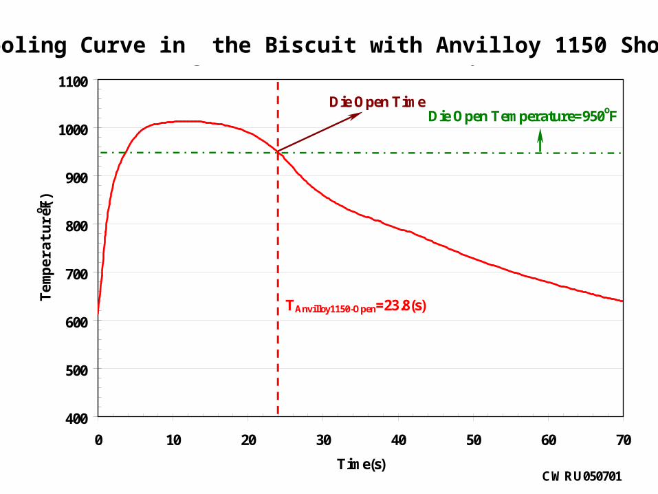
) Cooling Curves in the Biscuit with Anvilloy Shot Blocks
Die Open Temperature=950oF
CWRU050701
TAnvilloy1150-Open=23.8(s)
Die Open Time
Cooling Curve in the Biscuit with Anvilloy 1150 Shot Block

400
500
600
700
800
900
1000
1100
0 10 20 30 40 50 60 70
Time(s)
Tem
pera
ture
(o F
)
Cooling Curves in the Biscuit with CuBeC3 Shot Blocks
Die Open Temperature=950oF
CWRU10190
TCuBeC3-Open=18.2(s)
Die Open Time
Cooling Curve in the Biscuit with CuBe-C3 Shot Block

TH13-Open=28.6(s)
TMold XL-Open=20.0(s)
TAnvilloy 1150-Open=23.5(s)
TMold Ma-Open=18.0(s)
TCuBe-3C-Open=18.2(s)

Effect of Thermal Conductivity of the Shot Block
Material on Cooling Time of Biscuit at 950oF
0
5
10
15
20
25
30
35
0 20 40 60 80 100 120 140
Thermal Conductivity(Btu/ft.h.F)
Coo
lin
g T
ime(
s)
H13
Anvilloy
3C CuBe

Type of Material Cooling Time at 950oF(s)
Mold Max High(Cu-Base) 18.0CuBe-3C(Cu-Base) 18.2Mold Max XL(Cu-Base) 20.0CMW Anvilloy-1150(W-Base) 23.5H13(Fe-Base) 28.6
Effect of Shot Block Material on Cooling Time of Biscuit
Die Open” time (@950oF)for Brush Alloy 3C is 18.2 sec.vs. 28.6 sec. for H13. This is a 36% reduction in cycle time.

LIST OF NON-FERROUS CANDIDATE MATERIALS
Material C W Mo Fe Ni Ti Zr Cu Be Cr Nb SnCMW-Anviloy1150
90.00 4.00 2.00 4.00
Kulite-Kuldie 90.00 4.00 2.00 4.00
Allvac 718L 0.01 3.10 18.20 53.80 0.93 17.90 5.06
CSM-PM Mo 100
Brush-QMAX Copper Beryllium
0.20 Bal. 2.00
Brush-Nybril 360 Nickel Beryllium
Bal. 0.50 2.00
Brush-Nybril-FX1 Nickel Beryllium
Bal. 0.50 12.50 1.00
Brush NBCXBal. 0.5 12.5 1.2
Brush M220C0.4 Bal. 2.00
Brush ToughMet2 9.00 Bal. 6.00
Brush ToughMet3 15.00 Bal. 8.00
Nickel Beryllium
Nickel Beryllium

TOTAL CRACK AREA AFTER 15,000 THERMAL FATIGUE CYCLES (1"x1"x7")
0
100
200
300
400
500
600
Test Materials
Tot
al C
rack
Are
a (
x 10
6m
2)
1"X1"X7", WC7
P.G
. H13
/Oil
/49R
c
Boh
ler
W30
3/O
i/45
Rc
Bru
sh W
rou
ght
Nyb
ril F
X/4
4Rc
Bru
sh C
ast
Nyb
ril F
X/4
9Rc
Bru
sh W
rou
ght
Nyb
ril 3
60/3
5Rc
Bru
sh C
ast
Nyb
ril 3
60-1
/34R
c
Bru
sh C
ast
Nyb
ril 3
60-2
/ 35R
c
Boh
ler
W10
0/44
Rc
Kin
d R
PU
1/48
Rc
Kin
d T
Q1/
48R
c
Bru
sh Q
MA
X/2
4Rc
CS
M P
M M
o/20
Rc
CM
W A
nvi
loy
1150
/37R
c
Ku
lite
Ku
ldie
/33R
c

AVERAGE MAXIMUM CRACK LENGTH AFTER 15,000 THERMAL FATIGUE CYCLES (1"x1"x7")
0
5
10
15
20
25
30
35
40
45
50
Test Materials
Ave
rage
Max
Cra
ck L
engt
h (
x100
m)
1"X1"X7", WC7
Allv
ac I
N71
8/46
Rc
(Pit
tin
g D
epth
)
P.G
. H13
/Oil/
49R
c
Boh
ler
W30
3/O
i/45R
c
Bru
sh W
rou
ght
Nyb
ril F
X/4
4Rc
Bru
sh C
ast
Nyb
ril F
X/4
9Rc
Bru
sh W
rou
ght
Nyb
ril 3
60/3
5Rc
Bru
sh C
ast
Nyb
ril 3
60-1
/34R
c
Bru
sh C
ast
Nyb
ril 3
60-2
/ 35R
c
Boh
ler
W10
0/44
Rc
Kin
d R
PU
1/48
Rc
Kin
d T
Q1/
48R
c
Bru
sh Q
MA
X/2
4Rc
CS
M P
M M
o/20
Rc
CM
W A
nvi
loy
1150
/37R
c
Ku
lite
Ku
ldie
/33R
c

Total Crack Area
0
100
200
300
400
500
600
700
800
0 2500 5000 7500 10000 12500 15000
Thermal Cycles
To
tal C
rack
Are
a (x
10
6
m2) H13
NBCX-1
M220C-1
Nibryl 360
Cast- Nibryl 360
1"x1"x7", w c7
H13/Oil/49HRC
NBCX-1/42HRC
M220C-1/52HRC CAST-NIBRYL360/40HRC
NIBRYL360/35HRC

Average Maximum Crack Length
0
10
20
30
40
50
60
70
0 2500 5000 7500 10000 12500 15000
Thermal Cycles
Ave
rag
e M
ax C
rack
Len
gth
(x1
00
m) H13
NBCX-1
M220C-1
NIBRYL360
CAST-NIBRYL360
1"x1"x7", w c7
NBCX-1/42HRC
H13/Oil/49HRCM220C-1/52HRC
CAST-NIBRYL360/40HRC
NIBRYL360/35HRC

Soldering Damage at the Corners of Cu-Ni-Sn Thermal Fatigue Specimens
ToughMet 3 ToughMet 2 ToughMet 2 ToughMet 2
0.5”

Thermal Fatigue Damage in NBCX-1 and M220C-1
NBCX-1 M220C-1
Soldering
Thermal Fatigue Cracks
Thermal Fatigue Cracks
Cor
ner
0.5”

CORNER DAMAGE IN ALLVAC A-286(Iron-based w/ca.25% Ni)

CermeTi - Titanium Metal Matrix Composite
Composition: matrix Ti-6Al-4V + 10wt% TiC particles.
Manufacturing: by PM at Dynamet, Burlington MA.
Main application: Liner for shot sleeves.
Advantages: Low thermal conductivity (5.9 W/mK that is ca. 25% of H13)
Good resistance to soldering and dissolving in molten Al
Good wear resistance (@40HRC)

AVERAGE MAXIMUM CRACK LENGTH OF CermeTi-C-10 vs. H13
0
10
20
30
40
50
60
70
80
0 2500 5000 7500 10000 12500 15000
Thermal Cycles
Ave
rag
e M
ax C
rack
Len
gth
(x1
00m
)
1"x1"x7", wC7
CermeTi-C-10 H13/oil quench/50HRC

COMPOSITION OF RECENTLY TESTED STEELS (spec.)
wt % P.G. H-13 Schmidt
H-11
Bohler
W302(H13)
Thyssen
2344(H13)
Kind
H-11
KDA1
C 0.40 0.49 0.39 0.40 0.38 0.38
Si 1.00 0.90 1.00 1.00 1.00 0.21
Mn 0.35 0.30 0.40 0.25 0.40 0.42
P 0.025 0.025 0.01 0.009 0.015max 0.01
S 0.001 0.05 0.002 0.001 0.005max 0.002
Cr 5.25 5.0 5.10 5.3 5.2 5.20
Mo 1.50 1.3 1.30 1.4 1.3 1.85
V 1.00 0.5 1.00 1.00 0.4 0.51
Cu 0.08 - 0.03
Ni 0.15 - 0.09 0.6 0.3
W -

TOTAL CRACK AREA OF ALLVAC WH38 AND H13
0
50
100
150
200
250
300
350
400
450
500
550
600
650
5000 7500 10000 12500 15000
Thermal Cycles
To
tal C
rack
Are
a (
x106
m2 )
WH38 H13
2"X2"X7", WC7
H13 / OIL / 51HRC
WH38 / 50HRC

AVERAGE MAXIMUM CRACK LENGTH OF ALLVAC WH38 AND H13
0
5
10
15
20
25
30
35
40
45
50
55
60
5000 7500 10000 12500 15000
Thermal Cycles
Ave
rag
e M
ax C
rack
Len
gth
(x1
00m
)
HW38
H13
2"X2"X7", WC7
H13/ OIL/ 51HRC
WH38 / 50HRC

TOTAL CRACK AREA OF wH38-3 AND H13
0
20
40
60
80
100
120
140
160
180
5000 7500 10000 12500 15000
Thermal Cycles
To
tal C
rac
k A
rea
(x
10
6m
2 )
WH-38-3 H13
2"X2"X7", WC7
H13 / OIL / 51HRC
WH38-3/43HRC

TOTAL CRACK AREA OF wH38-3 AND H13
0
20
40
60
80
100
120
140
160
180
5000 7500 10000 12500 15000
Thermal Cycles
To
tal C
rac
k A
rea
(x
10
6m
2 )
WH-38-3 H13
2"X2"X7", WC7
H13 / OIL / 51HRC
WH38-3/43HRC

AVERAGE MAXIMUM CRACK LENGTH OF WH38-3 AND H13
0
2
4
6
8
10
12
14
16
18
20
5000 7500 10000 12500 15000
Thermal Cycles
Av
era
ge
Ma
x C
rac
k L
en
gth
(x
10
0
m)
WH38-3 H13
2"X2"X7", WC7
H13/ OIL/ 51HRC
WH-38-3/43HRC

TOTAL CRACK AREA OF SCHMIDT H11 AND H13
0
50
100
150
200
5000 7500 10000 12500 15000Thermal Cycles
To
tal C
rack
Are
a (
x 10
6 m
2 )
H13 SCHMIDT/H11-ESR
2"X2"X7", WC7
H13 / OIL / 51HRC
SCHMIDT/H11-ESR/45HRC

AVERAGE MAXIMUM CRACK LENGTH OF SCHMIDT H11 AND P.G. H13
0
5
10
15
20
5000 7500 10000 12500 15000Thermal Cycles
Ave
rag
e M
ax C
rack
Len
gth
(x1
00m
)
H13 SCHMIDT/H11-ESR
2"X2"X7",WC7
H13 / OIL/ 51HRC
SCHMIDT/H11-ESR/45HRC

TOTAL CRACK AREA OF BOHLER 302 AND P.G. H13
0
50
100
150
200
5000 7500 10000 12500 15000
Thermal Cycles
To
tal C
rack
Are
a (
x106
m2 ) H13 BOHLER W302
2"X2"X7", WC7
H13 / OIL / 51HRC
W302/47HRC

AVERAGE MAXIMUM CRACK LENGTH OF BOHLER W302 AND P.G. H13
0
5
10
15
20
5000 7500 10000 12500 15000
Thermal Cycles
Ave
rag
e M
ax C
rack
Len
gth
(x1
00m
)
2"X2"X7", WC7
H13 / OIL/ 51HRC
W302/47HRC

TOTAL CRACK AREA OF THYSSEN 2344 AND P.G. H13
0
50
100
150
200
5000 7500 10000 12500 15000
Thermal Cycles
To
tal C
rack
Are
a (
x106
m2 )
2"X2"X7", WC7
H13 / OIL / 51HRC
THYSSEN 2344/45HRC

AVERAGE MAXIMUM CRACK LENGTH OF THYSSEN 2344(H13) AND P.G. H13
0
5
10
15
20
5000 7500 10000 12500 15000
Thermal Cycles
Ave
rag
e M
ax C
rack
Len
gth
(x1
00m
)
H13 2344
2"X2"X7", WC7
H13 / OIL/ 51HRC
Thyssen 2344/47HRC

TOTAL CRACK AREA OF KIND H11 AND P.G. H13
0
50
100
150
200
250
300
5000 7500 10000 12500 15000
Thermal Cycles
To
tal C
rack
Are
a (
x106
m2 )
2"X2"X7", WC7
H13 / OIL / 51HRC
KIND H11/47HRC

AVERAGE MAXIMUM CRACK LENGTH OF KIND H11 AND P.G. H13
0
5
10
15
20
25
5000 7500 10000 12500 15000
Thermal Cycles
Ave
rag
e M
ax C
rack
Len
gth
(x1
00m
)
2"X2"X7", WC7
H13 / OIL/ 51HRC
KIND H11/47HRC

TOTAL CRACK AREA OF KDA1 AND H13
0
20
40
60
80
100
120
140
160
180
5000 7500 10000 12500 15000
Thermal Cycles
Tota
l C
rack
Are
a (
x 10
6 m
2 )
KDA1 H13
2"X2"X7", WC7
H13
KDA1

AVERAGE MAXIMUM CRACK LENGTH OF KDA1 AND H13
0
2
4
6
8
10
12
14
16
18
5000 7500 10000 12500 15000
Thermal Cycles
Av
era
ge
Ma
x C
rac
k L
en
gth
(x
10
0
m)
KDA1 H13
2"X2"X7", WC7
H13
KDA1

TOTAL CRACK AREA AFTER 15,000 THERMAL FATIGUE CYCLES
0
100
200
300
400
500
600
700
WH38
Kind H
11
Bohler W
302
Schm
idt H
11
P.G
.H13
Thysse
n 234
4
KDA1
WH38
-3
1016
3
Tota
l C
rack
Are
a (x
106
m2 ) 2"x2"x7",WC7
Bo
hle
r W
302
Sch
mid
t H
11
P.G
.H13
Th
ysse
n 2
344
KD
A1
WH
38-3
Kin
d H
11

AVERAGE MAXIMUM CRACK LENGTH AFTER 15,000 THERMAL FATIGUE CYCLES
0
10
20
30
40
50
60
70
WH38
Kind H
11
P.G
.H13
Schm
idt H
11
Bohler W
302
Thysse
n 234
4
WH38
-3
KDA1
1016
3
Ave
rag
e M
ax C
rack
Len
gth
(x1
00 m
)
2"x2"x7",WC7
P.G
.H13
Sch
mid
t H
11
Bo
hle
r W
302
Th
ysse
n 2
344
KD
A1
WH
38-3
Kin
d H
11