nail loads for truss connections using steel · pdf filenail loads for truss connections using...
TRANSCRIPT

NAIL LOADS FOR TRUSS CONNECTIONS USING STEEL VS. FIVE-PLY
AND FOUR-PLY FIR AND SPRUCE PLYWOOD GUSSETS
J. E. Turnbull and L. P. Lefkovitch
Engineering and Statistical Research Institute, Research Branch, Agriculture Canada, Ottawa, Ontario K1A 0C6
Contribution no. 1-730, Received 18 July 1985, accepted 13 March 1986
Turnbull, J. E. and L. P. Lefkovitch 1986. Nail loads for truss connections using steel vs. five-ply and four-plyfir and spruce plywood gussets. Can. Agric. Eng. 28: 167-173.
Traditional five-ply, 12.5-mm Douglas fir plywood has recently disappeared from the Canadian retail lumber market.Now the product is four-ply, 12.2-mm, which has shown consistently poorer performance when tested as connectinggussets for nailed wood roof trusses. This experiment examined some of the implications of the changes in CSA-0121Douglas fir plywood, and seeks a better alternative gusset/nail combination. The best connection tested was a two-member, three-gusset system using 0.91-mm (20-gage) steel side gussets and a 1.22-mm (18-gage) center gusset givinga unit lateral resistance of 3.15 kN/nail, compared with five-ply Douglas fir plywood at 0.99 kN/nail. Five-plyDouglasfir plywood in turn gave significantly higher ultimate unit lateralresistance (Nu) than four-ply Douglas fir and the spruceplywoods tested. However, at 1.27 mm slip, the unit lateral slip resistance values (Ns) for the Douglas fir plywoodsdid not show a significant strength advantage over the values for corresponding layups of spruce plywood.
INTRODUCTION
Canada Plan Service (CPS) roof trusseshave traditionally been designed withnominal 12.5-mm Douglas fir (D. fir)plywood gussets on two sides of 38-mmwood frames, nailed from both sideswith 4 x 64-mm concrete nails, basedon Turnbull and Theakston (1964). As analternative to factory-prefabricated press-plate trusses, this has given strong, predictable connections suitable for on-site
construction by relatively unskilled farmand construction workers.
Turnbull and Theakston (1964) alsotested spiral "Truss Gusset" nails madeespecially for this application by the SteelCo. of Canada. These nails were 4.9 x
65 mm, a little stronger and somewhatcheaper than the 4 x 64-mm concretenails. However, in some parts of Canadait has been hard to find the Truss Gusset
nails; therefore, the CPS trusses were laterrevised to use the widely available concrete nails.
Recently, Turnbull et al. (1981) gavesome alternatives to the simple three-member, double-shear nailed truss joint;they used doubled frame members andthree gussets to give three or four shearplanes per nail. The center gusset (between frames) was 0.91 mm (20 gage)galvanized steel and the outside gussetswere either 0.91 mm steel or 12.5 mm
plywood. The nails were 102 mm common spiral nails. The main benefit fromusingthese two-member, three-gusset systems was a doubling of the truss spacing(typically 1.2 to 2.4 m) and a halving ofthe total number of trusses and nails re
quired to make a given roof. Masse (1985)evaluated axial performance, as well ascombined axial-rotational effects, with
the same two-member, three-gusset nailsystem. His main objective was to refinethe overall design of CPS doubled rooftruss frames by considering all the primary and secondary member stresses asaffected by both axial and rotational stiffness characteristics of the joints.
A change in the Canadian StandardsAssociation (CSA) standard, Douglas firplywood (Anonymous 1978), allows a reduction from five to four veneer plies inthe nominal 12.5-mm layup, with a corresponding increase in the veneer thicknesses used. Considering typical lowerchord truss gussets stressed primarily intension parallel to the face grains, this reduces the minimum net thickness of the
plies effective in tension from 7.2 mm(five-ply) to only 4.8 mm (four-ply).
Another result of this change to four-ply plywood is that the two center veneershave grains running parallel to each other.The result is effectively a single centerveneer, more than twice the thicknessof any veneer in the previous five-plylayup. This may, under wet service, expand with much greater force, placinghigher preload shear stresses on the gluedboundaries. Farm building roof trusses,although normally not designed for wetservice, may in fact be subjected to occasional wetting due to winter condensation,and the wet periods can easily coincidewith maximum roof snow loads.
Since it is impractical to specify12.5-mm five-ply in a retail market nowsupplying only the four-ply product, thecurrent designs for CPS nailed trusses arenow in jeopardy. This experiment was undertaken to study some implications ofthis change of plywood standards and toseek an improved connection system.
CANADIAN AGRICULTURAL ENGINEERING, VOL. 28, NO. 2, SUMMER 1986
The initial short-term strength of trussjoints is a consideration, but the long-termperformance of the joints is more important. The typical environment in a livestock building may be quite conducive tocorrosion of metal fasteners and rotting oftruss members within the joints. Theselong-term performance considerations arebeyond the scope of this experiment.
PROCEDURES
Objectives and Test SpecimensIt was decided that this experiment
would follow the objectives of previouswork (Turnbull et al. 1981); that is, toseek an optimum truss connection madewith nails and gusset materials easily purchased in Canadian farming communities.To maximize the shear planes penetratedby each nail, the nail length would correspond closely to the total joint thickness.Nails would be driven from both sides ofthe joints, and they would be spaced tominimize wood splitting.
Figure 1 gives details of the A-frametest specimens and the joints. Each A-frame test simulated two heel joints of afarm roof truss. Tests were similar tothose made previously (Turnbull et al.1981) except that the numberof heel jointnails was increased (from 8 to 12 in thelower chords and from 9 to 13 in the upperchords). This made the gussets also liableto failure, on the chance that it might provide some verification of published plywood design stresses as applied to nailedtruss joints.
Turnbull et al. (1983) observed that, ina two-member three-gusset nailed joint,the center steel gusset is usually the first toreach failure stress. This is because each
167

\ * \**"^ • * • *I «**• • » • M •
I T I Ti l l I
B£ Lk^w^k^^ewtsaA^as^I I I
^kWlWfrlWWfrW^^ '
13 NAILS
•1800-
Figure 1. Details of test specimens. (A) 4.4 x 76-mm concrete nails; 0.91-mm galvanized steel side gussets; 1.22-mm galvanized steel centergusset. (B) 4.0 x 64-mm concrete nails; five-ply D. fir gussets. (C) 4.0 x 64-mm concrete nails; four-ply D. fir gussets. (D) 4.0 x64-mm concrete nails; five-ply spruce gussets. (E) 4.0 x 64-mm concrete nails; four-ply spruce gussets.
nail develops two shear planes about thesteel center gusset but only one shearplane at each plywood side gusset. Mass6(1985) in fact confirmed with strain gagesthat about 55% of the total joint forcepassed through the center steel gussetand only 22.5% passed through each plywood side gusset. In an all-steel gussetsystem(Fig. 1A, for example), where thenailsdo not penetrate the third gusset, perhaps up to 2/3 of the force goes to thecenter gusset.
For this reason system A (Fig. I) wasgiven a center gusset thicker than theoutside gussets, that is 1.22 mm centerversus 0.91 mm outside. The previoustests (Turnbull et al. 1981) used 0.91-mmgussets exclusively. In this test the carpenters used a 32-oz club hammer tohandle the tougher requirements of penetrating the 1.22-mm center gussets.
If successful in all respects, the all-steel gusset connection A as described inFig. 1 might replace the double-membertruss joints in some current CPS truss designs where plywood side and steel center
168
plates are used (Turnbull et al.1983).
1981,
Test ProcedureTest frames as detailed in Fig. 1 were
assembled using green wood (21.6-27.2% moisture), subsequently dried forabout 6 wk in a controlled atmosphere,then load-tested at 15.8-17.7% moisturecontent. The wood stock was no. 2 orbetter, S-P-F (spruce-pine-fir) speciesgroup, not tested or preselected for density. All threepartsforeachA-frame werecut from the same 38 x 235-mm plank.
Each of the five tests was replicated sixtimes making 30 specimens. The test apparatus was as used previously (Turnbullet al. 1981) with the hydraulic pump andcylinder calibrated to give 1.91 mm/minaverage piston velocity. This correspondsto a frame-to-gusset deformation rate of1.91 x 0.1763 = 0.336 mm/min, chosento correspond to the testingrate usedoriginallyby Turnbull and Theakston (1964).The factor 0.1763 was calculated from thegeometry of the A-frame test specimens,
using a Williot-Mohr diagram and the assumed elastic moduli of the frames and
gussets to convert from piston travel tojoint deformation. Thus for the single-member frames with plywood gussets,
X = 0.1763 (D - 0.1525P) (1)
and for the double-member frames withsteel gussets,
X = 0.1763 (D -0.076/') (2)
where X = joint deformation (mm), D =pistontravel (mm), P = pistonload(kN).
Joint deformation X in Eqs. 1 and 2 isa calculated average single-connectiondisplacement. It is based on the assumption that the upper chord-to gusset partand the gusset-to-lower chord part displaceequally, acting like two similarconnections in series. In fact, the nails perconnection and the forces at each connection are not identical, but the forces pernail are nearly identical. The terms (D -0.1525 P) and (D - 0.076P) adjust forthe slight increase in piston travel attributable to elastic deformations calculated
CANADIAN AGRICULTURAL ENGINEERING, VOL. 28, NO. 2, SUMMER 1986

TABLE I. NAILED JOINT FAILURE MODES
Test Gusset Test
series type no. Failure mode
A Steel 9 Nail bending4 Lower chord tension at knot
11 Nail bending25 Gussets torn at nail holes
29
1
Gussets torn at lower chord nailsLower chord tension at knots
B 5-ply D. fir 8 Nail bending10 Nail bending22 Nail bending24 Nail bending, tearing splits at top chord26 Nail bending, tearing splits at top chord27 Nail bending
C 4-ply D. fir 5 Lower chord tension
12 Heel gusset tension19 Nail bending20 Rolling shear in heel gusset28 Heel gusset tension30 Heel gusset tension
D 5-ply spruce 6 Heel gusset tension7 Nail bending
17 Nail bending18 Nail bending21 Heel gusset tension23 Nail bending
E 4-ply spruce 3 Heel gusset tension13 Heel gusset longitudinal shear15 Heel gusset tension16 Heel gusset delamination
2 Heel gusset delamination14 Nail bending
<O
<LU
for the wood frames and the steel or plywood gussets. These adjustments werebased on another Williot-Mohr diagram.Hydraulic piston travel D was registeredby two linear potentiometers, one mounted each side of the specimen ridge joint.Pairs of potentiometer readings and corresponding time and load data were printedout at 1-min intervals by a data-logger(Kaye Digistrip II).
The vertical resisting force developedat the ridge joint of each test frame wasindicated by a calibrated flat load cell(Strainsert Universal, Model FL25V-2SP)inserted between the hydraulic piston anda ball-jointed steel plate bearing on the topof the ridge joint. As with the deformations, the joint loads P were sensed indirectly at the ridge joint and converted toframe-to-gusset nail loads K, using thefollowing relationship:
Y = 0.1135/> (3)
where Y = frame-to-gusset load (kN/nail)and P = ridge joint load (kN).
The value of nail load Y in Eq. 3 wascalculated from the number of nails per
»W»»»«"»»»**«M»
2 3^56
FRAME-TO-GUSSET DEFORMATION X, mm
Figure 2. Mean nail load versus joint deformation, as tested at 1.91 mm/min deformation rate. Deformations (X) were not corrected for frameand gusset elastic strains.
CANADIAN AGRICULTURAL ENGINEERING, VOL. 28, NO. 2, SUMMER 1986 169

connection and the geometry of the A-frame, with all connections considered aspinned. However, because the centroidsof the nail groups did not coincide withthe member centerlines, the effectiveslope of the upper chords was taken as20° to the horizontal, not the 18.4° thatwould correspond with a 1/3 rafter slope.
During each test the data-logger wasprogrammed to scan the test load andthe paired potentimeter readings onceeach minute. The joint displacements ofparticular interest were X = 0.38 and1.27 mm, corresponding, respectively, tonail design loads traditionally used forhigh human occupancy (HHO) and lowhuman occupancy (LHO) farm buildingsas defined by the Task Group on FarmBuildings (1983). Using the method of cubic splines for interpolation, the values ofnail resistance Y corresponding to nailedjoint displacements X = 0.38 and 1.27mm were obtained. These 60 values (fivetests, six replications, two slips) werethen subjected to an analysis of variance.
The order of testing was randomized toeliminate bias due to operator experience,drying of wood, etc. The mode of failure(nails, gussets, frame, etc.) was noted.
RESULTS AND DISCUSSION
Statistical Analysis of Test LoadsThe ultimate test loads in Table III
were not statistically analyzed becauseof the complicating effects of other failures not related to the nailed joints (seeTable I).
All the test data in the range of jointslip from 0 to 2 mm were analyzed. Within this limited range the departures fromlinearity were minimal, although therewas occasional slight evidence of nonlinear behavior. Figure 2 shows meanperformance curves for the five jointtypes, although (unlike the analyzed data)these curves were not adjusted for framedeformations.
The analysis of variance of nail resistance values corresponding to joint slips0.38 and 1.27 mm showed that the steel
connections (series A) were significantlymore than twice as strong as all othertests, at both 0.38 and 1.27 mm slip (P <0.001). As expected, the series A connections (steel gussets) were also strongerthan the previous double-member connections (steel, and steel with five-plyD. fir) (Turnbull et al. 1981). This relationship was not statistically examined;however, the series A ultimate loads werelower than would be expected in relationto the previous steel and steel-plywoodstrengths.
Considering again the nail resistances
[7(1
Figure 3. Series A steel tests typical failure, due to tearing elongation of the nail hole.
Figure 4. Series C four-ply D. fir plywood failure, a diagonal failure due to tension in theplywood gusset.
at 0.38 and 1.27 mm slip, the five-plyplywoods produced significantly stiffernailed connections than the correspondingfour-ply plywoods (P = 0.035). Also, theD. fir plywood connections were significantly stiffer than those made with spruceplywoods (P < 0.001). There was no significant interaction between the wood species and the number of plies in this limitedrange of slip.
Failure Modes and Ultimate Nail Loads
Table I gives the failure mode for eachof the 30 tests. Failures due to nail
bending and gussets tearing at the nailholes were not abrupt (that is, the loadreached a peak value, then declined fromthis peak value as deformation continued
to increase). On the other hand, failuresdue to gusset or frame rupture wereabrupt.
Series A steel tests showed a varietyof failure modes; two were due to nailsbending, two to lower chord tension (atknots) and two to elongated nail holes tornin the steel gussets (Fig. 3). Gusset tearingwas more equally distributed between sideand center gussets, as compared with previous tests (Turnbull et al. 1981) where allthree gussets had been of equal thickness.
Series B five-ply D. fir plywood testsall failed in nail bending, at a mean loadof 3.61 kN/nail; this was 49% of themean failure load for the Series A steeltests. There was no apparent damage tothe five-ply D. fir plywood gussets except
CANADIAN AGRICULTURAL ENGINEERING, VOL. 28, NO. 2, SUMMER 1986
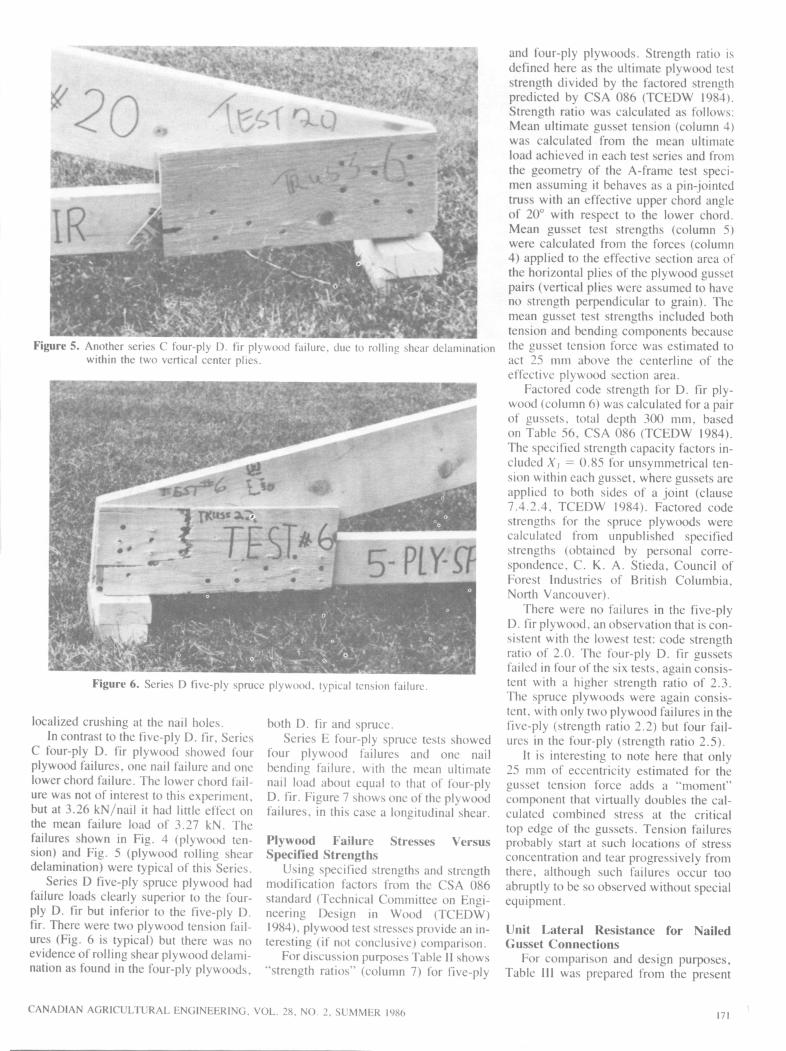
Figure 5. Another series C four-ply D. fir plywood failure, due to rolling shear delaminationwithin the two vertical center plies.
Figure 6. Series D five-ply spruce plywood, typical tension failure.
localized crushing at the nail holes.In contrast to the five-ply D. fir, Series
C four-ply D. fir plywood showed fourplywood failures, one nail failure and onelower chord failure. The lower chord failure was not of interest to this experiment,but at 3.26 kN/nail it had little effect onthe mean failure load of 3.27 kN. Thefailures shown in Fig. 4 (plywood tension) and Fig. 5 (plywood rolling sheardelamination) were typical of this Series.
Series D five-ply spruce plywood hadfailure loads clearly superior to the four-ply D. fir but inferior to the five-ply D.fir. There were two plywood tension failures (Fig. 6 is typical) but there was noevidence of rolling shear plywood delamination as found in the four-ply plywoods,
both D. fir and spruce.Series E four-ply spruce tests showed
four plywood failures and one nailbending failure, with the mean ultimatenail load about equal to that of four-plyD. fir. Figure 7 shows one of the plywoodfailures, in this case a longitudinal shear.
Plywood Failure Stresses VersusSpecified Strengths
Using specified strengths and strengthmodification factors from the CSA 086standard (Technical Committee on Engineering Design in Wood (TCEDW)1984),plywood test stresses provide an interesting (if not conclusive) comparison.
For discussion purposes Table II shows"strength ratios" (column 7) for five-ply
CANADIAN AGRICULTURAL ENGINEERING, VOL. 28. NO. 2. SUMMER 1986
and four-ply plywoods. Strength ratio isdefined here as the ultimate plywood teststrength divided by the factored strengthpredicted by CSA 086 (TCEDW 1984).Strength ratio was calculated as follows:Mean ultimate gusset tension (column 4)was calculated from the mean ultimate
load achieved in each test series and from
the geometry of the A-frame test specimen assuming it behaves as a pin-jointedtruss with an effective upper chord angleof 20° with respect to the lower chord.Mean gusset test strengths (column 5)were calculated from the forces (column4) applied to the effective section area ofthe horizontal plies of the plywood gussetpairs (vertical plies were assumed to haveno strength perpendicular to grain). Themean gusset test strengths included bothtension and bending components becausethe gusset tension force was estimated toact 25 mm above the centerline of the
effective plywood section area.Factored code strength for D. fir ply
wood (column 6) was calculated for a pairof gussets, total depth 300 mm, basedon Table 56, CSA 086 (TCEDW 1984).The specified strength capacity factors included X, = 0.85 for unsymmetrical tension within each gusset, where gussets areapplied to both sides of a joint (clause7.4.2.4, TCEDW 1984). Factored codestrengths for the spruce plywoods werecalculated from unpublished specifiedstrengths (obtained by personal correspondence, C. K. A. Stieda, Council ofForest Industries of British Columbia,North Vancouver).
There were no failures in the five-plyD. fir plywood, an observation that is consistent with the lowest test: code strengthratio of 2.0. The four-ply D. fir gussetsfailed in four of the six tests, again consistent with a higher strength ratio of 2.3.The spruce plywoods were again consistent, with only two plywood failures in thefive-ply (strength ratio 2.2) but four failures in the four-ply (strength ratio 2.5).
It is interesting to note here that only25 mm of eccentricity estimated for thegusset tension force adds a "moment"component that virtually doubles the calculated combined stress at the criticaltop edge of the gussets. Tension failuresprobably start at such locations of stressconcentration and tear progressively fromthere, although such failures occur tooabruptly to be so observed without specialequipment.
Unit Lateral Resistance for NailedGusset Connections
For comparison and design purposes,Table III was prepared from the present
171

Figure 7. Series E four-ply spruce plywood failure, in this case a longitudinal shear.
TABLE 11. PLYWOOD GUSSET STRENGTH COMPARISONS
1
Testseries
2
Gusset
type
3
No. ofgusset
failures
4
Mean ult
gussettension
(kN)
5
Meangusset test
strength(MPa)
6
Factoredcode
strength(MPa)
7
Test/codestrength
ratio
BC
1)
E
5-ply D. fir4-ply D. fir5-ply spruce4-ply spruce
0
4
2
4
45.7
39.441.039.6
42.3
54.738.055.0
21.223.817.2t2l.8t
2.02.3
2.2t2.5t
t Based onunpublished specified strengths for Canadian softwood plywood (personal correspondence fromC. K. A. Stieda, Council of Forest Industries of B.C., N. Vancouver).
TABLE III. RESISTANCE OF NAILED GUSSET CONNECTIONS
Test load, kN/nail at Unit lateralresistance (kN)
Test Gusset 0.38 mm 1.27 mm 6.00 mm
series type slip slip slipt N, A\,
A Steel 1.952* 5.046 7.36§ 3.15 4.73
B 5-ply D. fir 0.640 1.579 3.61 0.99 2.25
C 4-ply D. fir 0.520 1.528 3.27 0.96 2.04
D 5-ply spruce 0.525 1.575 3.24 0.98 2.03
E 4-ply spruce 0.477 1.457 3.II 0.91 1.94
(1981) 5-ply D. fir 1.03 2.36 4.26 1.47 2.66
(1964) 5-ply D. fir 0.95 1.87 3.37 1.17 2.11
(1981) Steel 1.41 4.14 8.07 2.59 5.04
(1981) Steel 5-ply D. fir 1.53 4.59 8.14 2.87 5.08
t Ultimate test load, with nail slip adjusted for elastic frame and gusset deformations (Eqs. I and 2).tLoads in boldface type were statistically analyzed. The standard error for comparing wood species is
0.044, and for comparing steel with wood species is 0.087.§Some steel tests reached maximum test load before 6.00 mm slip occurred.
and several previous tests. For design ofLHO farm buildings, nailed truss connections have been based traditionally ontest loads recorded at 1.27 mm (0.050inch) joint slip. The "service" lateral resistances (Ns) were the test loads per nailat 1.27 mm slip, factored by 0.625 to"normal" (10-yr) load duration. Similarlythe "ultimate" lateral resistances (Nu)were the ultimate test loads at 6 mm nailslip, also factored by 0.625 to give"normal" load duration. The lateral resistance values A', and Nu are used here as
defined in Clause 10.8.4.1 of the "limitstates design" version of the CSA standard (TCEDW 1984).
A general observation on the 1985 plywood nailed joint results in Table III isthat both JVS and Nu design values arelower than previous results. On the otherhand, the new A',, value for steel gussets isabout 10% greater than those given byTurnbull et al. (1981), due probably to theincreased thickness of the center steel gusset. However these new "Ultimate" andcorresponding A/u values for steel are 7%
lower than the corresponding previousvalues (Turnbull et al. 1981), a result thatmay be partly explained by the fact thatultimate loads achieved in two of the six
recent tests were limited by lower chordfailures (Table I).
Practical Aspects of Truss ConnectionsImportant aspects of these field-nailed
truss connections are that they should provide a maximum of predictable performance with a minimum level of carpentryskills, and seldom with any engineeringsite supervision. In terms of the numberofnails required to connect truss membersfor a given roof area and load condition,the steel gusset system A is by far the bestcompared with systems B and C. Unfortunately the carpenters found it was noteasy to drive the concrete nails throughthe steel gussets, particularly the thicker(1.22 mm) center gusset. There was noproblem with nail blunting or bending,but hard blows with a club hammer were
required to penetrate the steel. An alternative would be to predrill undersized pilotholes to make the nailing easier, but theextra labor probably makes this alternative impractical.
SUMMARY ANDRECOMMENDATIONS
Connection A with doubled framemembers and three steel gussets makesthe most efficient use of nails. With a unitlateral resistance N, = 3.15 kN/nail, theA-type connection at 1.27 mm displacement has more than three times the lateralresistance of any of the single-frame connections with paired plywood gussets.Part of this higher performance is due tomore planes of shear (3 vs. 2), part is dueto a thicker concrete nail (4.5 vs. 4.0 mmdiameter) and part is due to steel gussets.On the negative side, the ultimate strengthof the A-type connection was not up toexpectations, and it was hard to drive thenails through the thicker center plate,even with a heavy club hammer.
Comparing the plywood gusset types,all using the 4.0 x 63-mm concrete nails,the traditional five-ply D. fir plywood(series B) proved clearly superior to thefour-ply D. fir (C) and the spruce plywoods (D and E). The four-ply plywoods(C and E) both showed gusset failurespredominating. Checking the plywoodfailure stresses against factored strengthspredicted according to the wood designcode (TCEDW 1984) tended to confirmthe safety and consistency of the code.
For single-member trusses that makeup the greater part of the CPS truss designfamily, no satisfactory substitute was
172 CANADIAN AGRICULTURAL ENGINEERING, VOL. 28, NO. 1, SUMMER 1986

found for the five-ply D. fir gusset material that has virtually disappeared from themarket.
For double-member trusses, the triplesteel gussets with a thicker center gussetperformed very well, but these joints weredifficult to assemble without predrilling.
Further research with thicker five-plyor seven-ply D. fir plywood gussets isrecommended, for connecting single-member trusses. It is worth noting that76-mm concrete nails would be com
patible with the total thickness of two18.5-mm plywood gussets and one38-mm center member. Using 18.5-mmplywood would at least allow an adequateodd number of plies in the plywood lay-upand would better match the strength of the38-mm frame members to be connected.
ACKNOWLEDGMENTSThe authors gratefully acknowledge the
major contributions by engineering students
Scott Laking and Kevin McKague who builtthe test specimens and ran the performancetests for this project, and by technologistDon Lowe who supervised and carried outthe laboratory work. Helpful comments anddata by Dr. C. K. A. Steida, Council ofForest Industries of British Columbia, are alsoacknowledged.
REFERENCES
ANONYMOUS. 1978. Douglas fir plywood.CSA Standard 0121 -M1978, Canadian Standards Assoc, 178 Rexdale Blvd., Rexdale,Ont.
MASSE, D. 1. 1985. Design and analysis ofmulti-laminated nailed joint trusses. M.Sc.thesis, Faculty of Engineering, CarletonUniversity, Ottawa, Ont.
TASK GROUP ON FARM BUILDINGS.
1983. Canadian farm building code. National Research Council of Canada, Ottawa,Ont. NRCCpubl. no. 21312.
TECHNICAL COMMITTEE ON ENGI
NEERING DESIGN IN WOOD. 1984.
CANADIAN AGRICULTURAL ENGINEERING, VOL. 28, NO. 2, SUMMER 1986
Engineering design in wood (limit statesdesign). CAN3-086.1-M84, Can. Stds.Assoc, 178 Rexdale Blvd., Rexdale, Ont.
TURNBULL, J. E., L. P. LEFKOVITCH,and D. M. LOWE. 1981. Multilaminated
nailed truss connections. Can. Agric Eng.23: 113-119.
TURNBULL, J. E., D. I. MASSE, and D. J.BUCKLEY. 1983. First experiences with anew facility for testing wood-framed farmroof trusses, diaphragms and rigid frames.Can. Agric Eng. 25: 101-109.
TURNBULL, J. E. and F. H. THEAKSTON.1964. Analysis of plywood gusset connections with steel nails. E1C-64-BR and
STR3, Division paper of the Eng. Inst, ofCan. 2: 2, March.
173