name of paper – machine drawing
TRANSCRIPT
Name of Paper – Machine Drawing
Topic – Assembly Drawing
Module – 1 Introduction (1 Min)
Module – 2 Types of Assembly Drawing (2 Min)
Module-3 Procedure of Assembly Drawing (5 Min)
Module-4 3D Modeling and Animation (4 Min)
Objective
After going through this content you will be able to
1. Identify individual components/ parts of the given object 2. Identify the standard parts in the given object. 3. Examine the parts and their sections in the given object to determine the
need of manufacturing. 4. Represent dimensions of the parts of the given object in drawing. 5. Assemble the given parts with respect to their relative position. 6. Prepare the bill of material in the specified format for the given object. 7. Prepare sub-assembly drawing of the given object 8. Prepare assembly drawing of the given object 9. Model the assembled drawing.
TEXT
An engineering drawing is used to fully and clearly define requirements for engineered items. It is not merely the drawing of pictures of an object but it is a graphical language that communicates ideas and information from one mind to another. This information not only communicates about the shape and size of an object but also helps in its production.
Module -1 Introduction
For Drawing of small objects such as Chair, Sofa Set, Dining Table, Fan, Almirah etc.,
simple two or three views may be drawn to explain completely the shape and size of the given object. For drawing bigger and complex objects such as Bicycle, Scooter, Television, Refrigerator, Car etc., this method of drawing simple two or three views of the whole object is not sufficient for understanding of basic feature and its reproduction.
The question arises, then how to draw these objects from production point of view. The answer is Assembly Drawing. In this e-content you will be learning about the assembly drawing creation and its modeling. What is an Assembly Drawing?
A drawing of complete unit, usually including minor details of its subcomponent is assembly drawing.

In an assembly drawing, or subassembly drawing, detailed parts, standard components and specifications come together in a unified way.
An assembly drawing shows how all of the parts of a multi-component design fit together, and are generally depicted as one or more orthographic projections.
Fig 1– Assembly Drawing of Feed Check Valve (3-Assemb-Drg)
Visual Courtsey: http://stlfinder.com/?search=Swing+Check+Valve+4%252526quot%25253B
Fig 1A: Exploded Assembly Drawing of Feed Check Valve
Visual Courtsey: https://grabcad.com/library/feed-check-valve-assembly
An assembly drawing is needed for all products or inventions that have more than one part. These drawings list all parts and sub-assemblies that make the final product. A BOM (Bill of Materials) on the drawing lists each part number, part name, and part quantity.
Some of these drawings provide instructions on how to assemble the product at a manufacturing level, while others may list part numbers for consumers to re-order parts. Instructions may include information such as how to fasten parts together, or what types of lubricant to use.

Module 2 - Types of Assembly Drawing
1. Design Assembly 2. General Assembly 3. Detail Assembly 4. Erection Assembly 5. Subassembly 6. Pictorial Assembly
Design Assembly
Design assemblies are used to show various kinematic relationships between components. Such assemblies are often made from sketches during the preliminary phases of a design process to study the relationships that exist between the components before the design is modeled.
Fig 2 - Design Assembly (slider crank mechanism and slider crank model)
Visual courtesy: http://mechanical-engineering-concepts.blogspot.in/2014/03/shaping-machine-application-f-quick.html
Visual courtsey: http://www.chegg.com/homework-help/questions-and-answers/slider-crank-mechanism-shown-idealization-automobile-crank-shaft-connecting-rod-piston-len-q3925617

The design assembly of Stop valve clearly shows the relative movement of valve and operating screw with the help of hand wheel. The movement of screw through the hand wheel allows the valve to move up because of incoming fluid pressure. Similarly the valve may be forced to sit back to its original position by pressure through screw.
Stop Valve
(Animation created through Adobe Flash)
This model also shows the relative motion in between the crank, connecting rod and piston. The crank is having circular motion whereas the piston and piston rod has reciprocating motion. At the same time the connecting rod possesses the non linear motion.
Single Acting Reciprocating Water Pump
(Animation created through Adobe Flash) General Assembly
A general assembly is the most common type of assembly drawing. It is displayed as a multi-view drawing and may contain a section view. General assembly does not contain dimensions.
Almost all the drawing shown in the various books is the examples of General Assembly. They are meant for illustration of shape and imagination of object during teaching and learning.
Fig 3 – General Assembly (2-Gen-Asmb)
Visual Courtsey:
http://www.stlfinder.com/3dmodels/dead+weight+safety+Valve
Visual Courtsey: https://www.flowstarvalveshop.com/pages/safety-relief-valves
Fig 3A – General Assembly (3-Gen-Asmb)
Ex. Sectioned assembled drawing of Plummer Block, Rivet Joints, Headstock and Tails stock are the examples of this. Where visualization of objet is of more importance than its dimensions.
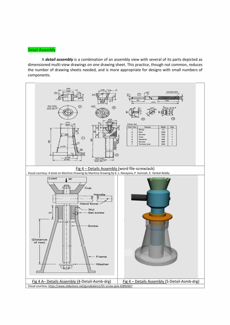
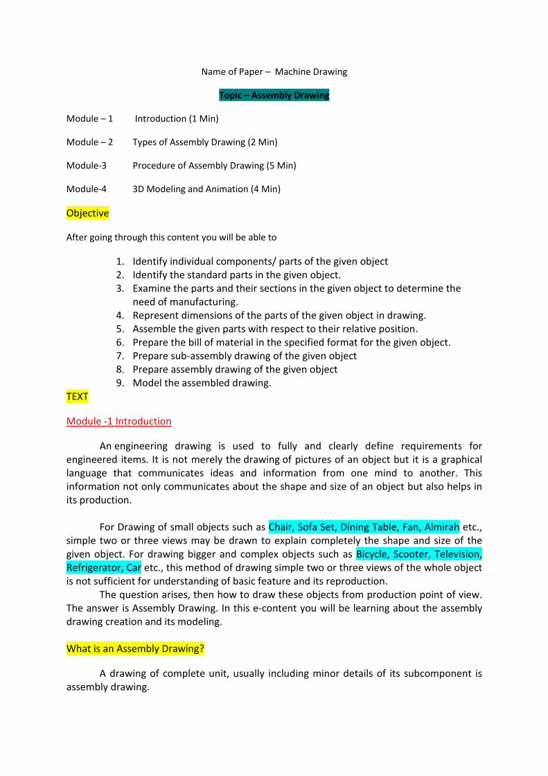
Detail Assembly
A detail assembly is a combination of an assembly view with several of its parts depicted as dimensioned multi-view drawings on one drawing sheet. This practice, though not common, reduces the number of drawing sheets needed, and is more appropriate for designs with small numbers of components.
Fig 4 – Details Assembly (
Visual courtesy: A book on Machine Drawing by Machine Drawing by K. L. Narayana, P. Kanniah, K. Venkat Reddy word file-screwJack)
Fig 4 A– Details Assembly (4-Detail-Asmb-drg) Fig 4 – Details Assembly (5-Detail-Asmb-drg) Visual courtesy: https://www.slideshare.net/gunabalans1/01-screw-jack-42892607

Erection Assembly
Similar to general assemblies, except dimensions and fabrication specifications are commonly included. Typically associated with cabinetry or products that are made from structural steel. Used for both fabrication and assembly.
Fig 5 – Erection Assembly (3-Erect-Asmb) Visual Courtsey:
http://www.steelconstruction.info/Construction
Subassembly Drawing
Complex or large assemblies may be communicated through subassembly drawings
Ex. Cars, Scooters, Bikes etc.
Pictorial Assembly
• Usually depicted as an isometric or perspective drawing. • May be rendered to imitate photographic quality.
Uses include: - Sales promotion
- Customer self-assembly - Maintenance procedures

Fig 6 – Pictorial Assembly (1-Picto-Asmb-Lever Safety Valve)
Fig 6 A– Pictorial Assembly (Opposed-piston-cyl)
Visual courtesy: https://www.technologyreview.com/s/420818/the-two-stroke-engine-reconsidered

Exploded Pictorial Assembly
Exploded pictorial assembly drawings are commonly used to show how individual components fit together.
Fig 7 – Exploded Pictorial Assembly (1-exp-pict-asmb)
Visual courtesy:
https://www.pinterest.com/jasonmegchelse/drawing-exploded/

In making an assembly drawing of an object following steps has to be adopted:-
Module -3 Procedure of Assembly Drawing(5 Min)
Identification of Components and Standard parts
By visual examination the object shall be broken in the maximum possible number of components and standard parts.
Preparation of Multi-view projection / Sectioning as per need
Orthographic projection of every component should be drawn. As per the requirement full/half sectioned view shall also be drawn for the better understanding of the shape and size of the component.
Placing of Components in their Relative Order
Once the above preparation is completed, the overall length and width of the assembly has to be calculated to plan for working area and scale factor. According to this a suitable plain scale has to be made first. Using this scale all the components can be placed one by one, one over the other.
Balloons A balloon is a circle that contains a single number, which is connected to an assembly
component with a leader line.
• All balloons on a drawing should be of the same size. • Balloons should be grouped together in an easy- to-read pattern. • Balloon numbers must correspond to item numbers in a parts list. • Balloons should not have horizontal or vertical leader lines.
Preparation of Parts list
A parts list is a table that contains information about each of the parts contained in an assembly. The item numbers correspond with the balloon numbers. Preparation of Part list is one of the important steps towards creation of Assembly Drawing. This clearly helps to draw following information
1. Item number – from balloons and name of component 2. Material used for fabrication of that component 3. The number of a particular part needed for the assembly 4. Standard of the Component (readymade availability / no need to be manufactured
separately)
Example of Parts List:-
Item No. Quantity Name Description Material 1 1 Body Cast Iron 2 1 Cover Cast Iron 3 1 Valve Feather Valve Gun Metal 4 1 Seat Gun Metal 5 1 Spindle Gum Metal 6 2 Split Pin (Fitted in the fulcrum) Mild Steel

7 4 Set Screw Mild Steel Location of Parts List
The location of a parts list usually depends on company standards. Common locations include:
• Above the title block – most common • Upper right corner • Upper left corner • Any other convenient location on the drawing
Fig 8 Balloons and Parts List (balloon)
Visual courtesy:
https://www.slideshare.net/bholapatel/assembly-drawing-53146699

Module-4 3D Modeling and Animation (4 Min)
The assembly drawing made using the above method has limited application, i.e. it possesses all inherent characteristic of pencil and paper work. To give this work a profession touch, the so produced drawing is modeled using CAD software and relevant modeling tools/software. The overall process of Modeling is as follows:-
1. Calculation of Work Space. 2. Creation of Layers 3. Creation of blocks for standard parts 4. Creation of Plan/Elevation of each component 5. Conversion of orthographic projection to isometric projection 6. Creation of Section view 7. Positioning of Different views as per their relative position 8. Adding material to each component using (Modeling tools/software) 9. Adding necessary motion to each component (as per the requirement of complexity of
shape) 10. Creation of Final Assembly
Description using Assembly Drawing of Lever Safety Valve (Animation)

Description of Script for Lever Safety Valve
1. The Body of the Lever safety valve is made of Cast Iron. It retains Seat. The seat is made of Gun Metal. It is screwed to the body. On the top of the body hole are made to fasten the body and Cover with the help of nuts and bolts.
2. Valve directly sits over the seat. Valve is made of Gun Metal. The valve is operated by Spindle
3. The Spindle and Valve are joined together with the help of Pin. The pin is locked to the valve using Split Pin.
4. The Seat, Valve and the Spindle is kept inside the body, and is covered with Body Cover. The cover is bolted on the top of the body. To prevent the leakage of fluid through the sides of the spindle Bush is also used.
5. It is made of Gun Metal and is placed at lower end of Body. Spindle passes through the bush and comes out of the body cover.
6. The Fulcrum pin is bolted over the body. Lever passes through it and Stirrup 7. The other end of the Spindle keeps a bearing on its top. The slot is made inside the stirrup to
accommodate the bearing. 8. The bearing, stirrup and the spindle are interlocked through Stirrup Pin. 9. A counter weight placed on the one end of the lever and weight is kept on the other end. 10. When the steam pressure exceeds to the designed pressure limit inside the body, the valve
and hence the complete unit move up till the stem passes away and designed pressure is regained.
11. In this way the whole assembly works.
Summary
Drawing is a language of engineer. Every object, existing or imaginative, is drawn through the principles of engineering drawing. It has certain method to show each and every minor detail of the components. It is very easy to show small objects like Chair, Sofa set, Almirah using principles of multi-view projection, but as the complexity of the object goes on increasing and more and more interior details need to be shown clearly the object is drawn component wise. Every component is placed as per their relative position and thus this smaller building block makes the complete object, which is known as assembly drawing. It is drawn in several ways as per the need. One of these pictorial assembly drawing and modeling is very common method from commercial aspects. That has been dealt in sufficient depth in this article.
FAQ 1. Define orthographic projection.
A two-dimensional graphical representation of an object in which the projecting lines are at right angles to the plane of the projection and parallel to themselves

2. Define multi-view projection.
A multi-view projection is a series of 2-dimensional orthographic projection which is drawn to completely demonstrate the shape and size of an object. The maximum possible no. of projections is limited to six.
3. Define Engineering Drawing. It is type of technical drawing, which is fully and clearly defines the requirements of engineered items. More than merely the drawing of pictures, it is also a language-graphical language that communicates ideas and information from one to another.
4. Define Technical Drawing.
It is a precise and detailed drawing of an object, as employed in architecture or engineering.
5. Define sketching.
It is a rough drawing of an object for illustration of its shape. 6. Define Balloons.
A balloon is a circle that contains a single number, which is connected to an assembly component with a leader line.
7. Define Part List. A parts list is a table that contains information about each of the parts such as
name, description, material and quantity. 8. Define, with an example, the term ‘standard component’.
A standard component is usually an individual part or component, manufactured in thousands or millions, to the same specification (such as size, weight, material etc...).
Ex. Steel bolt. Bolts are available in a vast range of standard sizes. However, each size is manufactured to an internationally accepted standard.
9. Name some Engineering Drawing Software. Autocad, Solid Works, Catia, Pro-E are some of the basic and advanced level software.
10. Name some 2D and 3D Modeling Tools. Director, Flash Animator, 3D- Studio Viz etc. are some of the Modeling Tools.
Quiz 1. A title block contains all of the following information, except:
a) Name and Address of the Company b) Part list c) Drawing sheet size and sheet letter designation d) Drawing Number
2. An Assembly Drawing normally consists of all of the following pieces, except: a) Parts drawn in their operating position b) Detail numbers of the parts c) Engineering change orders d) Bill of materials

3. A Balloon : a) often shows up on assembly drawings b) contains part number information c) indicates the scale of a removed detail d) appears at the end of a leader
4. A multi-view Assembly Drawing does not contains :
a) Component Detail b) Dimensioning c) Sections d) Relative positioning of components
5. Which of the following Assembly Drawing shows kinematic relationship between the components a) Design Assembly b) General Assembly c) Detail Assembly d) Erection Assembly
6. Erection Assembly is usually drawn when an Assembly is made of: a) Wood b) Brick c) Structural Steel d) Mortar
7. Which of the Assembly Drawing is used for modeling purpose? a) Sub-Assembly b) Erection c) Pictorial Assembly d) Multi-view Assembly
8. An Auto-CAD term that refers to pre-drawn object which is stored in a drawing file can be inserted into any other drawing file as needed is a …. a) Block b) Brick c) Balloon d) Part
9. Estimation of Work space is must, and it is done before starting of … a) Drawing b) Design c) Dimensioining d) Sectioning
10. To ensure equal scale factor in each component drawn, …………..is drawn at the beginning. a) Parts List b) Plain/ Diagonal Scale c) Title Block d) Border

Glossary Assembly Drawing:- Assembly drawing: Assembly drawings give us a big picture view of the
completed project. It shows how the components you may need to build fit together. These drawings include information about overall dimensions and the general arrangement of components. It is sometimes referred to as a general assembly drawing.
Sub Assembly Drawing:- Subassembly drawing is a type of drawing that shows how to put
together particular parts of the project.
Detail assembly drawing:- A detailed assembly drawing is a type of drawing that gives all the dimensions, fabrication methods, and types of materials required to manufacture the article. A detailed assembly drawing is also called a detailed drawing. References
Books
Machine Drawing by K. L. Narayana, P. Kanniah, K. Venkat Reddy
Machine Drawing by N. D. Bhatt Machine Drawing by P. S. Gill Machine Drawing by N. D. Junnarkar Web Material http://www.my-product-engineer.com/assembly-drawing.html
https://knowledge.autodesk.com/ https://grabcad.com/library/knuckle-joint-detail-parts-in-2d-dwg-file-1
http://www.gtuidp.com/eg-mech-room/cotter-and-knuckle-joints http://www.dictionary.com/ https://en.wikipedia.org/wiki/Multiview_orthographic_projection https://en.wikipedia.org/wiki/Engineering_drawing https://en.wikipedia.org/wiki/Technical_drawing http://www.technologystudent.com/ http://metal.brightcookie.com/2_draw/draw_t1/htm/draw1_2_1.htm
Software Used Autocad R-14 or higher 3D Studio Viz Solid works