nand reliability improvement with controller assisted ... · nand reliability improvement with ....
TRANSCRIPT

NAND Reliability Improvement with
Controller Assisted Algorithms in SSD
Sunghoon Cho Flash Tech Development Division
SK hynix
Santa Clara, CA August 2013
1
Introduction Program Operation -. Controller assisted ISPP algorithms
Erase Operation -. Erase Pulse Control
-. Intelligent ISPE
Read Operation -. Selected W/L Gr. / Unselected W/L Gr.
-. Read Refresh
Conclusions
Contents
Santa Clara, CA August 2013
2
Santa Clara, CA August 2013
3
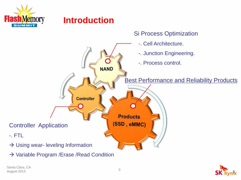
Introduction
Controller Application -. FTL
Using wear- leveling Information
Variable Program /Erase /Read Condition
Best Performance and Reliability Products
Si Process Optimization -. Cell Architecture.
-. Junction Engineering.
-. Process control.
3

Scaling Barriers in NAND Flash
[ NAND Flash Structure ]
Isol
atio
n Geometry Small Coupling Ratio, Small On Current
Narrow Operating Window Interference, Disturbance, P/E cycling Stress
Process Sensitivity Less Tolerance in Process Variation
Gat
e
Santa Clara, CA August 2013
4

Santa Clara, CA August 2013
ISPP Operation
-. Controller assisted ISPP algorithms as P/E cycles proceeds.
Program Operation
5

Santa Clara, CA August 2013
Programming time is decreased
Performance and Reliability Characteristics as P/E Proceeds.
After P/E cycling, cell Vth is rapidly increased and Vth distribution is widened, which means that performance of NAND flash is enhanced but reliability is degraded. We could transfer sufficient program performance margin to insufficient reliability margin as P/E cycle proceeds. Consequently, we have devised a method that can improve reliability by utilizing such characteristics.
6
Programming Time RBER
0.0
0.2
0.4
0.6
0.8
1.0
0.0
0.2
0.4
0.6
0.8
1.0
RBERt P
ROG
[a.u
.]
P/E cycles
Santa Clara, CA August 2013
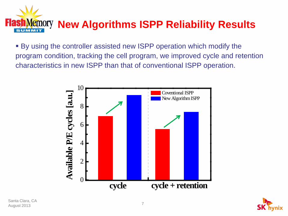
New Algorithms ISPP Reliability Results
By using the controller assisted new ISPP operation which modify the program condition, tracking the cell program, we improved cycle and retention characteristics in new ISPP than that of conventional ISPP operation.
7
Coventional ISPP New Algorithm ISPP
0
2
4
6
8
10
cycle cycle + retention
Avai
labl
e P/E
cycle
s [a.
u.]
Santa Clara, CA August 2013
Erase Pulse Control
Intelligent ISPE
Variable Erase Verify
Erase Operation
8

Era
se B
ias [
V]
1st pulse 2nd pulse 3rd pulse
Time [us] Santa Clara, CA August 2013
Erase Pulse Control Erase pulse shapes have been changed to enhance reliability and satisfy erase time requirement in erase pulse steps Steep erase pulse slope could satisfy erase time requirement but it could be tunnel oxide degradation.
Erase pulse shapes have been changed to enhance reliability and satisfy erase time requirement in erase pulse steps. Lowering rising erase pulse slope could reduce tunnel oxide stress but longer erase time is inevitable.
Era
se B
ias [
V]
1st pulse 2nd pulse 3rd pulse
Time [us]
Erase pulse shapes have been changed to enhance reliability and satisfy erase time requirement in erase pulse steps. We could implement new erase operation that can reduce the FN stress and
achieve fast erase operation simultaneously. The 1st erase pulse has graded slope and 2nd erase pulse has steep slope as in figure
Era
se B
ias [
V]
1st pulse 2nd pulse 3rd pulse
Time [us] 9

Santa Clara, CA August 2013
Erase Pulse and FN Current Larger FN current flows during 1st ISPE pulse step and its graded erase pulse slope relieve the FN stress in tunnel oxide. Since potential of floating gate rise after 1st ISPE pulse step, FN current decrease in low potential region of 2nd ISPE pulse. Even if 2nd step pulse slope is changed into steep, it does not affect cell
reliability.
< Erase Pulse and FN current using HSPICE >
VF.G
VTox
VC.C
Volta
ge [a
.u.]
Cur
rent
[a.u
.]
Time [a.u.] 10
Santa Clara, CA August 2013
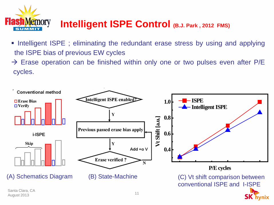
Intelligent ISPE ; eliminating the redundant erase stress by using and applying the ISPE bias of previous EW cycles Erase operation can be finished within only one or two pulses even after P/E cycles.
Intelligent ISPE Control (B.J. Park , 2012 FMS)
(A) Schematics Diagram (B) State-Machine (C) Vt shift comparison between conventional ISPE and I-ISPE
11
0.4
0.6
0.8
1.0
Vt S
hift
[a.u
.]
P/E cycles
ISPE Intelligent ISPE

Santa Clara, CA August 2013
Variable Erase/Program Verify Level in P/E Cycle Nodes
▪ NAND Cell degradation characteristics can be beneficially used because erase verify, program verify and read level can be manipulated as P/E cycles. Especially, erase verify level should be delicately controlled since erase stress is the major factor for cell degradation.
12
0.1
0.2
0.3
0.4
0.5
0.6
0.7
0.8
Cell
Vth
[a.u
.]
P/E cycle
Program Vth Erase Vth
Santa Clara, CA August 2013
Read Operation
Selected W/L Group Read
Unselected W/L Group Read
Read Scrub / Read Refresh
13

0 10 20 30 40 50 60 W/L position
Normal Read WL Group Read
0
2
4
6
8
10
Num
ber o
f fai
l bit
[a.u
.]
Santa Clara, CA August 2013
W/L Group Operation : Selected W/L
As scale down, cell uniformity within a block is being worsened continuously. To overcome these ones, W/Ls are divided into several groups and different operation biases are applied for each W/L groups with controller assistance or NAND itself.
Gr. A Gr. C Gr. D Gr. B
14

Santa Clara, CA August 2013
DSL
D
SSL
WL Group A
With increasing string size, series resistance of cells are also increased. As a result, string current is varied with W/L positions. We could use each different biases for each “W/L Groups” to compensate the variation of the string resistance.
W/L Group Operation : Unselected W/L
B
C
15

W/L Gr.D Conventional W/L Gr.A
0.0 0.2 0.4 0.6 0.8 1.00.0
0.2
0.4
0.6
0.8
1.0
Cell
Curr
ent [
a.u.
]
Gate Bias [a.u.]
Santa Clara, CA August 2013
Selected W/L Unselected W/L Value
W/L Group A VPASS_A VPASS_D + α
W/L Group D VPASS_D VPASS_D
W/L Group Operation : Cell Current By using the W/L group scheme, we can make the cell current of “Gr. A”similar to that of “Gr. D”.
16
W/L Gr.D Conventional W/L Gr.A New Scheme W/L Gr.A
0.0 0.2 0.4 0.6 0.8 1.00.0
0.2
0.4
0.6
0.8
1.0
Cell
Curr
ent [
a.u.
]
Gate Bias [a.u.]

Santa Clara, CA August 2013
Read Scrub / Read Refresh
Start 1’st Block
Read Cycle >*N?
Processing ECC N
Y
Updating Information of PGM Date
-.R.R.M ( Read Refresh Management )
-. *N : Read cycle criteria ( ~3k Read )
-. n : error bits per chunk
Ending Data RePGM
Last Block ?
Y
N
R.R.M.
Re PGM the data into other BLK
N
**n > 80% of ECC? Y
▪ Read Scrub is used for detecting retention and read disturbance. ▪ Controller could trace read count using R.R.M., which re-program the block if the number of fail bits is more than 80% of ECC coverage.
17
Santa Clara, CA August 2013
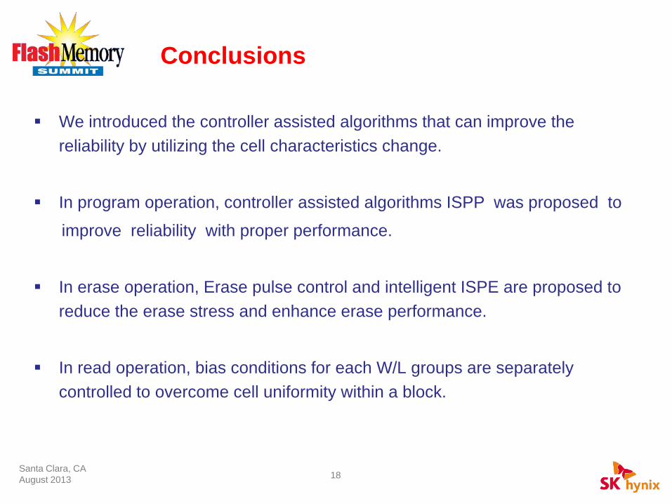
Conclusions
We introduced the controller assisted algorithms that can improve the reliability by utilizing the cell characteristics change.
In program operation, controller assisted algorithms ISPP was proposed to
improve reliability with proper performance.
In erase operation, Erase pulse control and intelligent ISPE are proposed to reduce the erase stress and enhance erase performance.
In read operation, bias conditions for each W/L groups are separately controlled to overcome cell uniformity within a block.
18