nao mi project software user requirements documentdocs/wht/naomi/wht-naomi-83/wht-naomi-83.pdfnao mi...
TRANSCRIPT

NAO MI Software URD $Revision: 1.3 $
$Id: urd.rtf,v 1.3 1996/09/17 10:52:25 abg Exp $ 1
NAO MI Project Software User Requirements Document
wht-naomi-83
Version 3.1
UK-AO programme document number:
AOW-SOF-APD-3.0-96/08/19
Authors: A B Gentles RGO A J Longmore ROE D F Buscher, R M Myers Durham AIG

NAO MI Software URD DRAFT $Version$
$Id: urd.rtf,v 1.3 1996/09/17 10:52:25 abg Exp $
Contents
CONTENTS 2
DOCUMENT HISTORY 8
INTRODUCTION 8
Purpose and Scope 8
What the system is expected to do 8
GENERAL DESCRIPTION 10
Control Loops 10 N-1 WFS-DM control loop 11 N-4 DM-TCS auto-focus loop 11 N-3 Optimisation Loop 11 N-1 WFS-FSM control loop 11 N-4 TTS-FSM control loop 11 N-1 FSM-TCS control loop 11 N-3 WFS-WFS XY pick-off control loop 11 N-4 WFS-self focus loop 11 N-1 TCS-ADC control loops 11
Opto-Mechanical components 12
Product Perspective 15
User Characteristics 15
Assumptions and Dependencies 16
Operational Environment 16
System functionality overview. 16
RTCS CONTROL PARAMETERS 17
REQUIREMENT TYPES AND TAG HIERARCHY 18
CONSTRAINTS 18 N-1 Constraint SYS.USE.WHT 18 N-1 Constraint SYS.CONTROL.GHRIL 18 N-1 Constraint SOFT.COMP.OBSSYS.DRAMA.CON 19 N-1 Constraint SOFT.COMP.SI.DRAMA.CON 19 N-1 Constraint MECH.EPICS.CON 19 N-1 Constraint MECH.EPICS.IFACE.CON 19 N-1 Constraint MMI.X11.CON 19 N-1 Requirement SOFT.CONSOLE.EXIST.CON 19 N-1 Requirement SOFT.SOURCE.AVAILENG.CON 19 N-1 Requirement SOFT.VERSIONS.REVERT.CON 19

NAO MI Software URD DRAFT $Version$
$Id: urd.rtf,v 1.3 1996/09/17 10:52:25 abg Exp $
Control files 19 N-1 Constraint CONF.SYS.FILE.TYPES.CON 19 N-1 Constraint CONF.SYS.FILE.VERSIONS.CON 20 N-1 Constraint CONF.SYS.FILE.ASCII.CON 20
FUNCTIONS: NAOMI-1 SYSTEM. 21 N-1 Requirement CEN.MMI.MON.DISP.FUNC 21 N-1 Requirement CEN.MMI.MON.DISP.SUPIX.FUNC 21 N-1 Requirement CEN.MMI.MON.ENABLE.FUNC 21 N-1 Requirement CONF.MMI.OPEDIT.FUNC 21 N-1 Requirement CONF.SYS.PREVNIGHT.REVERT.FUNC 21 N-1 Requirement DM.MMI.CTL.DISPSCALE.FUNC 21 N-1 Requirement DM.MMI.CTL.PATT.FUNC 21 N-1 Requirement DM.MMI.MON.DRIVE.FUNC 21 N-1 Requirement DM.RTCS.PWRDOWN.FUNC 21 N-1 Requirement DM.RTCS.ZEROVOLTS.FUNC 21 N-1 Requirement DM.RTCSWFSLOOP.FUNC 21 N-1 Requirement DMACTPOS.MMI.CTL.FUNC 21 N-1 Requirement DMACTPOS.MMI.MON.SCOPE.FUNC 21 N-1 Requirement ENGMODE.MMI.ALLCONF.FUNC 21 N-1 Requirement ENGMODE.MMI.EDITCONF.FUNC 21 N-1 Requirement ENGMODE.MMI.EXIST.FUNC 22 N-1 Requirement ENGMODE.MMI.GHRILCONSOLE.FUNC 22 N-1 Requirement ENGMODE.MMI.ITACONSOLE.EXIST.FUNC 22 N-1 Requirement ERROR.MMI.MON.DISP.FUNC 22 N-1 Requirement ERROR.MMI.MON.INSPECTLOG.FUNC 22 N-1 Requirement ERROR.MMI.MON.LOG.FUNC 22 N-1 Requirement ERROR.MMI.MON.LOG.SIZE 22 N-1 Requirement ERROR.MMI.MON.ORDER.FUNC 22 N-1 Requirement GUI.MMI.GEN 22 N-1 Requirement MECH.POST 22 N-1 Requirement MECH.STUB.FUNC 22 N-1 Requirement MESSAGE.MMI.MON.ALL.FUNC 22 N-1 Requirement MESSAGE.MMI.MON.DISP.FUNC 22 N-1 Requirement MESSAGE.MMI.MON.LOG.FUNC 22 N-1 Requirement MESSAGE.MMI.MON.TIME.FUNC 22 N-1 Requirement MMI.MON.WFSPIX.DISP.FUNC 23 N-1 Requirement POST.RTCS.EXIST.FUNC 23 N-1 Requirement RTCS.MMI.CTL.PARAM.FUNC 23 N-1 Requirement RTCS.MMI.MON.PARAM.FUNC 23 N-1 Requirement RTCS.MMI.MONVARS.DISP.FUNC 23 N-1 Requirement SLOPE.MMI.MON.DMANDWFS.FUNC 23 N-1 Requirement SLOPE.MMI.MON.REFDISP.FUNC 23 N-1 Requirement SLOPE.MMI.MON.SUPIX.FUNC 23 N-1 Requirement VIS.DATA.RTCS.BUFSIZE 23 N-1 Requirement VIS.DATA.RTCS.FUNC 23 N-1 Requirement VIS.RTCS.STORE.FUNC 23 N-1 Requirement WFS.MMI.CTL.TWEAK.WFSPOS.FUNC 23 N-1 Requirement WFS.MMI.MON.PIXANDTGTDISP.FUNC 23 N-1 Requirement WFS.MMI.MON.PIXDISP.RATE. 24 N-1 Requirement WFS.MMI.MON.TGTDISP.ENABLE.FUNC 24 N-1 Requirement WFS.MMI.MON.TGTDISP.FUNC 24 N-1 Requirement WFSADC.MECH.TELSLAVE.FUNC 24 N-1 Requirement WFSDMLOOP.MMI.CTL.OPCLOSE.FUNC 24 N-1 Requirement WFSDMLOOP.MMI.MON.GAIN.FUNC 24 N-1 Requirement WFSDMLOOP.MMI.MON.STATUS.FUNC 24 N-1 Requirement WFSDMLOOP.RTCS.ZONAL.FUNC 24 N-1 Requirement WFSFSMLOOP.RTCS.FUNC 24 N-1 Requirement WFSXYLOOP.MMI.CTL.OPCLOSE.FUNC 24

NAO MI Software URD DRAFT $Version$
$Id: urd.rtf,v 1.3 1996/09/17 10:52:25 abg Exp $
N-1 Requirement WFSXYLOOP.MMI.MON.GAIN.FUNC 24 N-1 Requirement WFSXYLOOP.MMI.MON.STATUS.FUNC 24
FUNCTIONS: NAOMI-2 SYSTEM. 25 N-2 Requirement 3DDISP.MMI.CTL.WF.FUNC 25 N-2 Requirement 3DDISP.MMI.MON.DM.FUNC 25 N-2 Requirement 3DDISP.MMI.MON.DM.RATE 25 N-2 Requirement 3DDISP.MMI.MON.EXIST.FUNC 25 N-2 Requirement 3DDISP.MMI.MON.USEWITHOUT.FUNC 25 N-2 Requirement 3DDISP.MMI.MON.WF.FUNC 25 N-2 Requirement 3DDISP.MMI.MON.WF.RATE 25 N-2 Requirement CONF.SYS.DEFAULT.REVERT.FUNC 25 N-2 Requirement CONF.SYS.DEFAULT.USEREDIT.FUNC 25 N-2 Requirement CONF.SYS.RESTORS.FUNC 25 N-2 Requirement CONF.SYS.USEREDIT.FUNC 25 N-2 Requirement CONF.SYS.USEREDIT.SOLN 25 N-2 Requirement CONF.SYS.VANILLA.FUNC 25 N-2 Requirement MESSAGE.MMI.MON.FILT.FUNC 26 N-2 Requirement PARALLEL.MMI.MECH.FUNC 26 N-2 Requirement SCITARG.MMI.ADDENTRY.FUNC 26 N-2 Requirement SCITARG.MMI.APPENDFILE.FUNC 26 N-2 Requirement SCITARG.MMI.EDITCURR.FUNC 26 N-2 Requirement SCITARG.MMI.EDITFILE.FUNC 26 N-2 Requirement SCITARG.MMI.GSSEARCH.FUNC 26 N-2 Requirement SCITARG.MMI.IF.FILE.FUNC 26 N-2 Requirement SCITARG.MMI.IF.SEL.FUNC 26 N-2 Requirement SHUTDOWN.SYS.SAVECONF.FUNC 26 N-2 Requirement SI.WFS.MMI.MONXYPOS.DISP.FUNC 26 N-2 Requirement SI.WFSXYPOS.MMI.CTL.ALIGN.PROC 26 N-2 Requirement SLOPE.MMI.MON.RATE.EXIST.FUNC 26 N-2 Requirement VIS.DATA.RTCS.BUFSIZE 26 N-2 Requirement VIS.FILTER.RTCS.FUNC 27 N-2 Requirement WFS.MECH.CTL.FUNC 27
FUNCTIONS: NAOMI-3 ADDITIONS. 28 N-3 Requirement 3DXDISP.MMI.MON.FUNC 28 N-3 Requirement ALLRESET.MMI.FUNC 28 N-3 Requirement CENCORR.MMI.CTL.DISPRATE.FUNC 28 N-3 Requirement CENCORR.MMI.CTL.SET.FUNC 28 N-3 Requirement CENCORR.MMI.CTL.TIME.FUNC 28 N-3 Requirement CENCORR.MMI.MON.DISP.FUNC 28 N-3 Requirement CENSPECTRUM.MMI.CTL.DISPRATE.FUNC 28 N-3 Requirement CENSPECTRUM.MMI.CTL.SET.FUNC 28 N-3 Requirement CENSPECTRUM.MMI.CTL.TIME.FUNC 28 N-3 Requirement CHASSIS.MECH.CTL.FUNC 28 N-3 Requirement GAINOPT.MMI.CTL.FUNC 28 N-3 Requirement ILOCK.MMI.ASKUSER.FUNC 28 N-3 Requirement ILOCK.MMI.MON.ILLUM.FUNC 28 N-3 Requirement ILOCK.MMI.PECBS.CTLOOPS.FUNC 28 N-3 Requirement ILOCK.MMI.RTCS.OBSCTLLIST.FUNC 29 N-3 Requirement ILOCK.SYS.LOOP.INIT.FUNC 29 N-3 Requirement ILOCK.SYS.SLEW.FUNC 29 N-3 Requirement INIT.SYS.PRECONFIG.LATENCY 29 N-3 Requirement INIT.SYS.PREOBS.LATENCY 29 N-3 Requirement INIT.SYS.ROTCENTRE.FUNC 29 N-3 Requirement MODES.MMI.MON.FUNC 29 N-3 Requirement OFFSETSEQ.MMI.CTL.SEQLENGTH 29 N-3 Requirement OFFSETSEQ.SI.MMI.CTLZE 29
NAO MI Software URD DRAFT $Version$
$Id: urd.rtf,v 1.3 1996/09/17 10:52:25 abg Exp $
N-3 Requirement OPCONSOLE.MMI.EXIST.FUNC 29 N-3 Requirement ORIENT.MMI.CTL.ALTAZ.FUNC 29 N-3 Requirement ORIENT.MMI.CTL.RADEC.FUNC 29 N-3 Requirement ORIENT.MMI.CTL.SKYPA.FUNC 29 N-3 Requirement ORIENT.MMI.MON.ALTAZ.FUNC 29 N-3 Requirement ORIENT.MMI.MON.RADEC.FUNC 30 N-3 Requirement ORIENT.MMI.MON.SKYPA.FUNC 30 N-3 Requirement PEC.MMI.MON.DISP.SOLN 30 N-3 Requirement QUICKSTART.MMI.CTL.FUNC 30 N-3 Requirement RZEROTIME.MMI.CTL.FUNC 30 N-3 Requirement SCITARG.MMI.IF.DIAL.FUNC 30 N-3 Requirement SI.MMI.CTL.GUI.FUNC 30 N-3 Requirement TELAGLOOP.MMI.CTL.PERIOD.FUNC 30 N-3 Requirement TELAGLOOP.MMI.CTL.RANGE.DYRANGE 30 N-3 Requirement TELAGLOOP.MMI.MON.ERROR.FUNC 30 N-3 Requirement TELAGLOOP.MMI.MON.SCOPE.FUNC 30 N-3 Requirement TELAGLOOP.RTCS.EXIST.FUNC 30 N-3 Requirement TELFOCLOOP.MMI.CTL.PERIOD.FUNC 30 N-3 Requirement TELFOCLOOP.RTCS.FUNC 30 N-3 Requirement TELFOCLOOP.RTCS.RATE 31 N-3 Requirement TELFOCLOOP.RTCS.STABILITY 31 N-3 Requirement TTGEN.MMI.CTL.AMP 31 N-3 Requirement TTGEN.MMI.CTL.SEQDEF 31 N-3 Requirement TTGEN.MMI.CTL.SEQLEN 31 N-3 Requirement TTGEN.MMI.CTL.SEQLOOP 31 N-3 Requirement TTGEN.RTCS.OUTPUT.FUNC 31 N-3 Requirement TTGEN.RTCS.SYNC.FUNC 31 N-3 Requirement TZEROTIME.MMI.CTL.FUNC 31 N-3 Requirement VIS.MMI.CTL.FILTER.FUNC 31 N-3 Requirement VIS.MMI.CTL.FILTER.LIMITS.FUNC 31 N-3 Requirement VIS.MMI.CTL.FILTER.SIGTHR.FUNC 31 N-3 Requirement VIS.MMI.CTL.FILTER.SLPTHR.FUNC 31 N-3 Requirement WFS.MMI.MONXY.SLEWRATE.FUNC 31 N-3 Requirement WFSDMLOOP.RTCS.MODAL.FUNC 32 N-3 Requirement WFSXY.MMI.CTL.SLEWRATE.FUNC 32
FUNCTIONS: NAOMI-4 ADDITIONS. 33 N-4 Requirement OSPADC.MECH.TELSLAVE.FUNC 33 N-4 Requirement SIADC.MECH.TELSLAVE.FUNC 33 N-4 Requirement TTSADC.MECH.TELSLAVE.FUNC 33 N-4 Requirement CEN.MMI.MONCORR.DISP.RATE 33 N-4 Requirement CEN.PEC.MMI.MONTRUM.DISP.FUNC 33 N-4 Requirement CEN.PEC.MMI.MONTRUM.DISP.RATE 33 N-4 Requirement CHASSIS.MMI.MON.FUNC 33 N-4 Requirement CONF.SYS.OPTSCI.FUNC 33 N-4 Requirement DIMM.MMI.MON.FUNC 33 N-4 Requirement EXTIM.GUI.MMI 33 N-4 Requirement GAINATC.MMI.MON.FUNC 33 N-4 Requirement GAINOPT.MMI.MON.FUNC 33 N-4 Requirement ILOCK.MMI.MON.COVERS.FUNC 33 N-4 Requirement ILOCK.SYS.COVERS.FUNC 34 N-4 Requirement INIT.SYS.TCSCALIB.FUNC 34 N-4 Requirement INIT.SYS.TCSCALIB.FUNC 34 N-4 Requirement LIGHTS.MMI.MON.FUNC 34 N-4 Requirement LOG.SYS.ENVDATA.FUNC 34 N-4 Requirement MESSAGE.MMI.MON.CLEAR.FUNC 34 N-4 Requirement OBS.SYS.ADDHEADERS.FUNC 34 N-4 Requirement OFC.MMI.CTL.CENTRE.FUNC 34 N-4 Requirement OFC.MMI.CTL.ZOOM.FUNC 34
NAO MI Software URD DRAFT $Version$
$Id: urd.rtf,v 1.3 1996/09/17 10:52:25 abg Exp $
N-4 Requirement OFC.MMI.CTL.ZOOM.SOLN 34 N-4 Requirement OFC.MMI.MON.ALIGSRC.DISP.FUNC 34 N-4 Requirement OFC.MMI.MON.DISP.FUNC 34 N-4 Requirement OFC.MMI.MON.DISP.RATE 34 N-4 Requirement OFC.MMI.MON.SLIT.DISP.FUNC 34 N-4 Requirement OFC.SI.MMI.MONFIELD.DISP.FUNC 35 N-4 Requirement OFC.TTS.MMI.MONXYPOS.DISP.FUNC 35 N-4 Requirement OFC.WFS.MMI.CTLXYPOS.DISP.FUNC 35 N-4 Requirement OFC.WFS.MMI.MONXYPOS.DISP.FUNC 35 N-4 Requirement OFFSETSEQ.MMI.CTL.FUNC 35 N-4 Requirement OFFSETSEQ.MMI.CTL.LATENCY 35 N-4 Requirement OPT.RTCS.CONT.FUNC 35 N-4 Requirement OPT.RTCS.EXPSTATIC.FUNC 35 N-4 Requirement OPT.RTCS.GOALSET.FUNC 35 N-4 Requirement OPT.RTCS.OFF.FUNC 35 N-4 Requirement PEC.MMI.MON.DISP.FUNC 35 N-4 Requirement PEC.MMI.MONBS.FUNC 35 N-4 Requirement PECBS.MMI.CTL.FUNC 35 N-4 Requirement PSF.SYS.CALC.NOFUNC 35 N-4 Requirement RTCS.WFSFOC.LOOP.FUNC 36 N-4 Requirement RZERO.MMI.MON.FUNC 36 N-4 Requirement RZERO.MMI.MON.SCOPE.FUNC 36 N-4 Requirement SEEING.MMI.MON.FUNC 36 N-4 Requirement SI.MMI.CTL.ABORT.FUNC 36 N-4 Requirement SI.MMI.CTL.BASIC.FUNC 36 N-4 Requirement SI.MMI.CTL.INTTIME.FUNC 36 N-4 Requirement SI.MMI.CTL.MODE.FUNC 36 N-4 Requirement SI.MMI.CTL.RUN.FUNC 36 N-4 Requirement SI.MMI.CTL.WIN.FUNC 36 N-4 Requirement SI.MMI.MON.IMAGE.FUNC 36 N-4 Requirement SI.MMI.MON.IMAGE.LATENCY 36 N-4 Requirement SI.MMI.MON.IMAGE.RATE 36 N-4 Requirement SI.TEL.MMI.MONPOS.FUNC 36 N-4 Requirement SI.WFS.MMI.MONXYPOS.SUPER.FUNC 36 N-4 Requirement SIM.MMI.FUNC 36 N-4 Requirement TCSFOCLOOP.MMI.CTL.OPCLOSE.FUNC 37 N-4 Requirement TEL.MMI.CTL.ACTIVEDRAG.FUNC 37 N-4 Requirement TEL.MMI.CTL.ACTIVEDRAG.RATE 37 N-4 Requirement TEL.MMI.CTL.MOUSE.FUNC 37 N-4 Requirement TEL.MMI.CTL.PASSIVEDRAG.FUNC 37 N-4 Requirement TEL.MMI.CTL.POINT.FUNC 37 N-4 Requirement TEL.MMI.CTL.REMOTE.FUNC 37 N-4 Requirement TEL.MMI.CTL.REMOTE.PERF 37 N-4 Requirement TEL.MMI.MON.FOCERROR.FUNC 37 N-4 Requirement TEL.MMI.MON.FOCSCOPE.FUNC 37 N-4 Requirement TEL.MMI.MON.PARAMS.FUNC 37 N-4 Requirement TELOFFLOCK.RTCS.FUNC 37 N-4 Requirement TTLOOP.MMI.CTL.OPCLOSE.FUNC 38 N-4 Requirement TTLOOP.MMI.MON.STATUS.FUNC 38 N-4 Requirement TTS.MMI.CTL.FUNC 38 N-4 Requirement TTS.MMI.CTL.TWEAK.TTSPOS.FUNC 38 N-4 Requirement TTS.MMI.CTLXY.ACTIVEDRAG.FUNC 38 N-4 Requirement TTS.MMI.CTLXY.ACTIVEDRAG.RATE 38 N-4 Requirement TTS.MMI.CTLXY.FUNC 38 N-4 Requirement TTS.MMI.CTLXY.MOUSE.FUNC 38 N-4 Requirement TTS.MMI.CTLXY.PASSIVEDRAG.FUNC 38 N-4 Requirement TTS.MMI.CTLXY.TTSPOS.FUNC 38 N-4 Requirement TTS.MMI.CTLXY.TTSPOS.PERF 38 N-4 Requirement TTS.MMI.MON.PIXDISP.FUNC 38

NAO MI Software URD DRAFT $Version$
$Id: urd.rtf,v 1.3 1996/09/17 10:52:25 abg Exp $
N-4 Requirement TTS.MMI.MON.SCOPE.FUNC 38 N-4 Requirement TTSFSMLOOP.RTCS.FUNC 38 N-4 Requirement TZERO.MMI.MON.FUNC 39 N-4 Requirement TZERO.MMI.MON.SCOPE.FUNC 39 N-4 Requirement WFS.MMI.CTL.CENALG.SELECT.FUNC 39 N-4 Requirement WFS.MMI.CTLFSMLOOP.GAIN.FUNC 39 N-4 Requirement WFS.MMI.CTLFSMLOOP.OPCLOSE.FUNC 39 N-4 Requirement WFS.MMI.CTLXY.ACTIVEDRAG.FUNC 39 N-4 Requirement WFS.MMI.CTLXY.ACTIVEDRAG.RATE 39 N-4 Requirement WFS.MMI.CTLXY.MOUSE.FUNC 39 N-4 Requirement WFS.MMI.CTLXY.PASSIVEDRAG.FUNC 39 N-4 Requirement WFS.MMI.MON.CENALG.STATUS.FUNC 39 N-4 Requirement WFS.MMI.MONFSMLOOP.GAIN.FUNC 39 N-4 Requirement WFS.MMI.MONFSMLOOP.STATUS.FUNC 39 N-4 Requirement WFSAF.RTCS.OPCLOSE.FUNC 39 N-4 Requirement WFSAF.RTCSLOOP.EXIST.FUNC 39 N-4 Requirement WFSAF.RTCSLOOP.RATE 39 N-4 Requirement WFSAFLOOP.MMI.CTL.GAIN.FUNC 39 N-4 Requirement WFSAFLOOP.MMI.CTL.OPCLOSE.FUNC 40 N-4 Requirement WFSAFLOOP.MMI.MON.GAIN.FUNC 40 N-4 Requirement WFSAFLOOP.MMI.MON.STATUS.FUNC 40 N-4 Requirement WFSBGND.SYS.FUNC 40 N-4 Requirement WFSBGND.SYS.SOLN 40 N-4 Requirement WFSDMLOOP.MMI.CTL.WFSFOC.FUNC 40 N-4 Requirement WFSDMLOOP.MMI.MODESEL.FUNC 40 N-4 Requirement WFSDMLOOP.MMI.MON.WFSFOC.FUNC 40 N-4 Requirement WFSDMLOOP.WFSFOC.RTCSOFF.FUNC 40 N-4 Requirement WFSDMLOOP.WFSFOC.RTCSON.FUNC 40 N-4 Requirement WFSTILT.RTCS.CON 40 N-4 Requirement WFSWFSXY.RTCS.LOOP.FUNC 40
DEFINITIONS, ACRONYMS AND ABBREVIATIONS 41
Definition of terms used 41
Acronyms and Abbreviations 41
REFERENCES 42
CROSS-REFERENCE BETWEEN PREVIOUS URD REQUIREMENTS AND HIERARCHICAL TAGS. 43

NAO MI Software URD DRAFT $Version$
$Id: urd.rtf,v 1.3 1996/09/17 10:52:25 abg Exp $
Document History Table 1 Document History
Version 1.0 Jan 1996 All Produced in latex for the WHT NGS system, refined many times and agreed by Durham and RGO as the current software description.
Version 2.0 Aug. 1996 AJL, RMM Produced following restructuring of project to formally include E-1 and to stage delivery to reduce costs.
Version 3.0 Sept. 1996 ABG Converted to Word 6 format. Split requirements into functional and constraint Split functional requirements into groups for evolutionary development
Version 3.1 Sept. 1996 ABG changed tag hierarchical structure.
Introduction An adaptive optical system is to be built for the William Herschel telescope(WHT), sited on La Palma, that will correct image aberrations caused by turbulent seeing cells in the earth's atmosphere. It is intended as a telescope facility which will provide a corrected focus where general purpose instruments can be mounted. It is known by the acronym NAOMI (Nasmyth Adaptive Optics for Multi-purpose Instrumentation). This user requirements document (URD) describes the assumptions made about the user(s) of this system, its place in the telescope environment and, most importantly, the top level requirements for the complete software system, as viewed by the user(s) through GUIs and visualisation aids. The first section deals with general issues, the second section describes the software as a product and how it is likely to be used in a normal environment, for observing with the first light near-IR science instrument. The third section details the specific formal requirements for the system which are derived from section two. Several Appendices are used to describe proposals for operational procedures which provide for calibration alignment and for imaging and spectroscopic modes of astronomical observation.
Purpose and Scope This document contains the requirements for the software systems needed to operate the NGS AO system to be built for the WHT and is aimed primarily at the developers of the software. It is also part of a structured definition of what is to be built. It is intended to provide enough information to describe the software requirements and detailed operational concepts of the NGS AO system. The document should be read in conjunction with the Scientific and Operational Requirements Document (AOW/SYS/RMM/6.0/07/96), the Technical Description Document (AOW/GEN/AJL/6.8/07/96) and the Work Package cover documents. The Scientific and operational Requirements Document defines the formal top-level requirements of the whole NAOMI system and is the document which has been agreed to define the scope and performance of the final system. The Technical Description Document gives a description of a proposed implementation. This URD expands on user requirements in significantly more detail, giving full guidelines to what will need to be developed in the software to meet the top-level requirement. A description of the operational environment covers the relevant parts of the telescope environment that will need to be interfaced to the AO system, and a brief overview of the operation of the system is given. Specific requirements then follow, split into capabilities and constraints. They are traced to aspects of the observing scenarios detailed in appendices???. Following the adoption of the principle of maximal re-use of ELECTRA software in the NAOMI project, this document has been annotated to show where requirements are part of the ELECTRA-1 system, ELECTRA to NAOMI (baseline) reworking or a preserved future upgrade route. Where no indication is given, it should be assumed that a requirement is in the baseline: where an explicit indication of baseline status is given this is done to emphasise the inclusion of a particular requirement.
What the system is expected to do NAOMI will correct for the atmospheric seeing, to provide a close-to- diffraction-limited image on-axis with a bright star, as defined in the TOP-LEVEL SCIENTIFIC AND OPERATIONAL REQUIREMENTS. Performance with fainter stars will be correspondingly degraded, down to the limiting magnitude given in the TECHNICAL DESCRIPTION OF NAOMI. Correction of the seeing will adapt to follow the phase aberration as it varies with time. On a slower time scale, the algorithm used to compute the optimum correction signal will need to be modified to keep the correction signal optimised. An AO system improves the point spread function of an image fed to the selected Science Instrument. Different science instruments have differing criteria for what is considered “best” performance, and this leads to a corresponding need to adjust the AO system's internal functionality. At a lower level, it must

NAO MI Software URD DRAFT $Version$
$Id: urd.rtf,v 1.3 1996/09/17 10:52:25 abg Exp $
allow engineers to engage in off-line inspection and analysis of internal data, and must provide suitable facilities to visualise the on-line data so that users can confirm that the system is functioning normally. N-1 The operational concept for the baseline NAOMI system is one in which the adaptive optics
hardware and its own control software will operate largely stand-alone, but with important but minimal interfaces to the instrument and to the telescope control systems existing to provide a limited number of key functions.
N-1 The software defined by this document must implement the necessary closed-loop servo control of the optical elements, and allow development of an extensible control system that will operate as an integral part of the telescope control and data acquisition systems.
N-1 Efficient operation of the system is required to minimise the time spent setting the system up, and to maximise the time spent measuring the corrected focal image plane with a scientific instrument.
N-4 The NGS AO system can be used as a telescope subsystem, under the control of the WHT System Computer. Guide stars nominated by the user or chosen automatically by the AO system will be acquired and tracked within the context of a black-box, common-user operation and simple, pre-defined, criteria will be used to select the level of AO correction. Optimum correction performance is not expected in this mode, which is intended to minimise the effect upon the user of having AO correction turned on.
N-4 ?The AO system should also be able to be used with visiting science instruments that are not integrated into the WHT infrastructure. In this case, the functions of selecting guide stars, moving probes etc., needed as part of the acquisition process, and the closing of correction loops to lock the AO system should be available as subsidiary, and possibly automatic, functions of a single command to point the telescope at a source. Note that the WHT telescope acquisition &; guidance (TAG) task already has this functionality.
An additional operating mode allows the system fuller control of observations. In this mode, self-calibration procedures can be run and it will be possible to obtain specific scientific observations that depend on particular seeing conditions, or that require non-standard AO system configurations. upgrade It will be possible for the AO system to control the installed Science Instrument so that observational images are only taken when image quality exceeds a preset threshold. N-4 This system is part of a longer-term AO programme on the WHT. The NGS system software must
therefore provide for further developments and for evolution into a larger and more sophisticated instrument. It must also allow for general purpose measurements and experiments to be carried out during routine investigations into atmospheric seeing and system development.
The objectives of the AO system software are as follows:
Objective 1 To implement an AO correction system with real-time control that, with a suitable opto-mechanical system, enables NAOMI to meet the performance Clauses 1 - 3 in the S.O.R..
Objective 2 To control the NAOMI opto-mechanical hardware at the telescope in a way that facilitates and where reasonable automates alignment, calibration and some standard observational procedures.
Objective 3 To support and facilitate alignment and calibration procedures in a preparation area in the WHT away from the GHRIL platform (S.O.R. clause 13).
Objective 4 To allow a science instrument to be fed with images corrected by the system, meeting Clauses 4 and 12 in the S.O.R. document.
Objective 5 N-1 To make the system sufficiently integrated with the telescope system(s) so that observing with the
AO system is efficient, in accordance with Clauses 5, 6 and 15 in the S.O.R.
Objective 6 To allow engineering level access for control of more sophisticated functions.
NAO MI Software URD DRAFT $Version$
$Id: urd.rtf,v 1.3 1996/09/17 10:52:25 abg Exp $
Objective 7 To allow information about the system to be stored, visualised and analysed by system developers (including real-time data streams).
Objective 8 To supply software written in accordance with the standards described in S.O.R. clauses 20, 22 and (documentation) 14.
What the system is not expected to do Once commissioned, the system is not expected to be used in any place other than the WHT GHRIL and the WHT instrument test area. AO correction performance is strongly dependent on the current atmospheric conditions as well as other factors such as the angular distance between the science target object and the guide star reference. There are many factors involved in selecting the optimum correction strategy depending on the scientific goals and the nature of the science instrument. Fully optimised correction will not be part of the baseline system, but at least one real-time optimisation algorithm shall be implemented in the baseline system. When operating with visiting, or otherwise non-integrated, science instruments, the AO system cannot be expected as a default option to provide more than the basic operational functionality outlined above. Availability of automatic error recovery procedures, for example, is likely to be restricted in any non-baseline operational modes.
General Description The WHT's AO system is intended to offer a common-user facility to improve images supplied to science instruments mounted at the GHRIL focus using a conventional phase-conjugate system operating in a closed-loop mode with natural guide stars. Modifications may be made to the system at a later date to incorporate operation with laser guide stars. The ability to meet specifications detailed in the TOP-LEVEL SCIENTIFIC AND OPERATIONAL REQUIREMENTS requires that the system is able to operate with dim stars with a visual magnitude of at least 15 or 16, and that atmospheric conditions are sufficiently favourable to allow a guide field diameter of about 3 arcminutes. The AO system is constructed on an optical bench situated at the WHT's f/11Nasmyth GHRIL area, and a breakdown of the system into its constituent sub-assemblies is shown in figure1. Note that each opto-mechanical or hardware component that can be moved or sensed under software control is termed a mechanism in this document. This includes those components that are used to implement the adaptive phase correction, as well as those that direct optical beams around the system. Each mechanism with the AO system is likely to have local positional control loops to move the hardware to the required demand position and keep it there. In this context, a control loop takes input from one mechanism (such as the wavefront sensor, for example) and provides a position demand signal for another mechanism (such as the deformable mirror). Mechanisms and control loops that are currently expected to be part of the AO system are described below.
Control Loops Adaptive correction is achieved by measuring phase aberrations with a wavefront sensor (WFS). An aberration surface is then calculated and applied to a deformable mirror (DM) so that the detected aberrations are cancelled out. Not surprisingly, the applied correction adapts as the atmosphere changes with time. In any practical implementation of an AO correction system, the dynamic range of the DM is limited and is unable to cope with any large deviations needed to correct for significant image motion caused by full aperture tilt. Thus, a separate fast steering mirror (FSM) is needed to correct for full aperture tilt. N-2 It is likely that the FSM may work better when its control loop is fed from a dedicated wavefront
sensor; this is referred to as a tip/tilt sensor (TTS). Thus an upgrade to the system to be implemented for the WHT could have two wavefront sensors (WFS &; TTS) as well as the two correcting mirrors which are part of the baseline (DM & FSM). Each of the sensors is mounted on a pick-off probe in order to detect light from off-axis guide stars.
As well as the positions and focusing of the pick off probe(s), it will be necessary to adjust the telescope focus and make changes to the field position by offsetting the telescope. Several control loops exist within the AO system. They are:
NAO MI Software URD DRAFT $Version$
$Id: urd.rtf,v 1.3 1996/09/17 10:52:25 abg Exp $
N-1 WFS-DM control loop N-1 This is the wavefront sensor / deformable mirror control loop. When this is closed, the deformable
mirror is controller in real-time using data from the WFS. Its purpose is to remove aberrations caused by seeing and intrinsic residual telescope imperfections and as such is the main control loop in the AO system.
N-4 DM-TCS auto-focus loop N-4 This is the deformable mirror / telescope secondary auto-focus control loop. When it is closed, the
position of the telescope secondary is servo-ed using the mean DM defocus signal to keep the DM in the centre of its stroke range. Only occasional adjustments should be necessary as the telescope focus is very stable.
N-3 Optimisation Loop N-3 Outwith the WFS-DM loop is a subsidiary control loop monitoring the WFS-DM loop data streams in
order to estimate the current correction performance of the system. Its function is to optimise the coefficients that are used in the main WFS-DM loop and therefore adapt the system parameters to take account of slowly varying changes in seeing conditions.
N-1 WFS-FSM control loop N-1 Full aperture tip/tilt information from the WFS is used to control the FSM. Note that this information
can feed the FSM-TCS subsidiary control loop which is specified below. The purpose of the WFS-FSM control loop is to provide an essentially jitter-free image.
N-4 TTS-FSM control loop N-4 This is the fast steering mirror and tip/tilt mirror control loop. When it is closed the tip/tilt mirror is
controlled in real-time using either the TTS or WFS tip/tilt signal. The FSM is used to relieve the DM of the stroke requirement for correcting whole image motion. A significant part of the aberrations present are caused by the whole image tip/tilt component.
N-1 FSM-TCS control loop N-1 This is the fast steering mirror/telescope control loop. When it is closed, the TCS is given commands
to keep the mean position of the FSM in the middle of its dynamic range. WFS-WFS pick-off control loop
N-3 WFS-WFS XY pick-off control loop N-3 This is the wavefront sensor/wavefront sensor XY pick-off control loop. When this is closed the WFS
pick-off position is servo-controlled using the mean tilt signal from the WFS. If the pick off is not placed precisely on the guide star in the field, the error will be measured as a WFS tip/tilt signal
N-4 WFS-self focus loop N-4 This is the wavefront sensor/self focus loop. It is only used in the laser guide star (LGS)
configuration. When it is closed, the WFS focus position is servo-ed using the WFS defocus signal. This will maintain the optimum focus position for the WFS and ensure that the LGS is correctly focused on to the WFS
N-1 TCS-ADC control loops N-1 This is the telescope control system / atmospheric dispersion corrector loop, and there is one for
each atmospheric dispersion corrector (ADC). The ADC is in the WFS arm of NAOMI. When the TCS-ADC loop is closed, the ADC is set and updated using the current TCS zenith angle. This maintains image quality at the wavefront sensors and science detectors which is essential to obtain the accuracy of correction required.
N-1 This loop is expected to be closed by default. It may be opened for engineering tests and alignment procedures. Procedures which open the loop are expected to ensure that it is closed again afterwards. Each procedure in the operational system should check that this loop is closed and warn the observer if it is not.

NAO MI Software URD DRAFT $Version$
$Id: urd.rtf,v 1.3 1996/09/17 10:52:25 abg Exp $
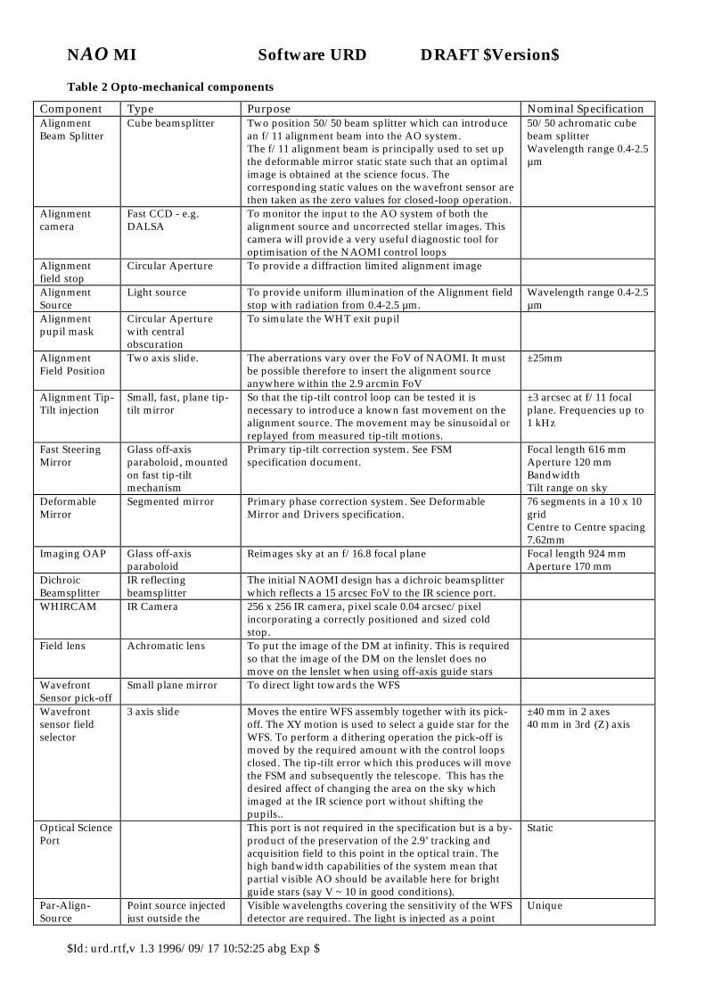
Opto-Mechanical components In order for the AO system to operate, a stellar reference object must be imaged on the wavefront sensor, and also on the TTS is fitted. Acquiring this object involves pointing the telescope at the field, optionally adjusting the telescope so that the object is correctly positioned within the science instrument field, and placing probes so that the light from a selected guide star within the field is directed to the wavefront sensors. This process may mean viewing the uncorrected Nasmyth focus, the corrected image, the IR science image and the image or signal from the wavefront sensor detectors. To achieve all this, and also to allow calibration of the detectors and positioning mechanisms, the system is expected to include the opto-mechanical components listed in Table 2. Note that this is a copy of the master list for mechanisms is in the Technical Description document (Reference 2). If there is any discrepancy between the T.D. and the following list, the T.D. list takes priority.
NAO MI Software URD DRAFT $Version$
$Id: urd.rtf,v 1.3 1996/09/17 10:52:25 abg Exp $
Table 2 Opto-mechanical components
Component Type Purpose Nominal Specification Alignment Beam Splitter
Cube beamsplitter
Two position 50/50 beam splitter which can introduce an f/11 alignment beam into the AO system. The f/11 alignment beam is principally used to set up the deformable mirror static state such that an optimal image is obtained at the science focus. The corresponding static values on the wavefront sensor are then taken as the zero values for closed-loop operation.
50/50 achromatic cube beam splitter Wavelength range 0.4-2.5 µm
Alignment camera
Fast CCD - e.g. DALSA
To monitor the input to the AO system of both the alignment source and uncorrected stellar images. This camera will provide a very useful diagnostic tool for optimisation of the NAOMI control loops
Alignment field stop
Circular Aperture To provide a diffraction limited alignment image
Alignment Source
Light source To provide uniform illumination of the Alignment field stop with radiation from 0.4-2.5 µm.
Wavelength range 0.4-2.5 µm
Alignment pupil mask
Circular Aperture with central obscuration
To simulate the WHT exit pupil
Alignment Field Position
Two axis slide. The aberrations vary over the FoV of NAOMI. It must be possible therefore to insert the alignment source anywhere within the 2.9 arcmin FoV
±25mm
Alignment Tip-Tilt injection
Small, fast, plane tip-tilt mirror
So that the tip-tilt control loop can be tested it is necessary to introduce a known fast movement on the alignment source. The movement may be sinusoidal or replayed from measured tip-tilt motions.
±3 arcsec at f/11 focal plane. Frequencies up to 1 kHz
Fast Steering Mirror
Glass off-axis paraboloid, mounted on fast tip-tilt mechanism
Primary tip-tilt correction system. See FSM specification document.
Focal length 616 mm Aperture 120 mm Bandwidth Tilt range on sky
Deformable Mirror
Segmented mirror
Primary phase correction system. See Deformable Mirror and Drivers specification.
76 segments in a 10 x 10 grid Centre to Centre spacing 7.62mm
Imaging OAP Glass off-axis paraboloid
Reimages sky at an f/16.8 focal plane Focal length 924 mm Aperture 170 mm
Dichroic Beamsplitter
IR reflecting beamsplitter
The initial NAOMI design has a dichroic beamsplitter which reflects a 15 arcsec FoV to the IR science port.
WHIRCAM IR Camera 256 x 256 IR camera, pixel scale 0.04 arcsec/pixel incorporating a correctly positioned and sized cold stop.
Field lens Achromatic lens To put the image of the DM at infinity. This is required so that the image of the DM on the lenslet does no move on the lenslet when using off-axis guide stars
Wavefront Sensor pick-off
Small plane mirror To direct light towards the WFS
Wavefront sensor field selector
3 axis slide Moves the entire WFS assembly together with its pick-off. The XY motion is used to select a guide star for the WFS. To perform a dithering operation the pick-off is moved by the required amount with the control loops closed. The tip-tilt error which this produces will move the FSM and subsequently the telescope. This has the desired affect of changing the area on the sky which imaged at the IR science port without shifting the pupils..
±40 mm in 2 axes 40 mm in 3rd (Z) axis
Optical Science Port
This port is not required in the specification but is a by-product of the preservation of the 2.9’ tracking and acquisition field to this point in the optical train. The high bandwidth capabilities of the system mean that partial visible AO should be available here for bright guide stars (say V ~ 10 in good conditions).
Static
Par-Align-Source
Point source injected just outside the
Visible wavelengths covering the sensitivity of the WFS detector are required. The light is injected as a point
Unique

NAO MI Software URD DRAFT $Version$
$Id: urd.rtf,v 1.3 1996/09/17 10:52:25 abg Exp $
corrected f/16.8 focus source into the WFS pick-off area. WFS Atmospheric Dispersion Corrector
2 pairs rotating prisms
Reduces effects of atmospheric dispersion for WFS star.
ADC
Wavefront Sensor Lenslet
10 x 10 lenslet array Lenslets which match one-to-one with the segments on the ELECTRA DM
10 x 10 array of square lenses Aperture of single lenslet 1mm Focal ratio of lenslets
WFS Shutter Remote control shutter. Remotely operated shutter
WFS Alignment Stage
WFS CCD automated stage.
See WFS specification Unique
Wavefront Sensor Detector
High-speed, low-noise, frame-transfer CCD. See WFS specification AOW/SUB/RAH/2.8/02/96
From a Software control and architecture perspective, the components are best described by the interfaces to them. They fall into three categories: ? ? Detectors ? ? Active and Adaptive optical elements ? ? Moving mechanisms (including statically positioned optics)
Detectors The detectors currently in the system are interfaced by the following means. ? ? Science Instrument
Control via DRAMA server task Monitoring of images via a DRAMA SDS parameter.
? ? Wavefront Sensor Control via serial port (TBC) Data arrives on several parallel cables with raw pixel data in continuous stream. (TBC)
? ? Pre Correction Camera No remote control facility Image data on Analogue Video co-axial cable. Monochrome format.
? ? Optical Field Camera No remote control facility Image data on Analogue video co-axial cable. Monochrome format.
Future upgrades are likely to contain: ? ? Tip tilt sensor
Control TBC Data stream format TBC
Active and Adaptive optical components These are the components which deliberately adjust the condition of the science optical beam. ? ? Fast Steering Mirror
Control via continuous 2 channel data stream, rate DC to 1 kHz No software feedback of position. (TBC)
? ? ELECTRA Deformable mirror Control via continuous 228 channel data stream, rate DC to 1 kHz. No software feedback of current position. Software position feedback possible later.
Remote controlled mechanisms Each mechanism can have one or more functions from the following set: ? ? Movement of item ? ? Position sensing of item ? ? Control of item (e.g. voltage to bulb)
NAO MI Software URD DRAFT $Version$
$Id: urd.rtf,v 1.3 1996/09/17 10:52:25 abg Exp $
? ? Monitoring of item state (e.g. door shut, measurement of light intensity) The NAOMI software is required to interface to the appropriate function set for each mechanism.
Product Perspective NAOMI will be installed at the GHRIL Nasmyth focus of the William Herschel telescope, and the AO correction hardware will reside within the GHRIL laboratory. The principal user interface to the AO system and to control of the WHT will be from the WHT control room. upgrade Operation of the system will be fully integrated with the WHT observing system, and also with the control and data reduction system for the first-light instrument. It is intended for use as a common user facility, built by specialists, maintained by on-island staff but capable of use, with trained support, by a visiting astronomer. The existing observing system uses ADAM, DRAMA and EPICS and, of these, DRAMA and EPICS are mandated for use in building new instruments. The AO system will need a basic interface to the WHT control and observing systems, and initially, the system will need to interface to the first light IR science detector. N-3 This system is to be used as an integral part of the WHT observing system, with overall control
coming from within the normal WHT environment N-3 Science data files, both optical and IR, that are produced as a result of AO observations will need to
contain information about the operation and status of the AO system in order to be reduced effectively. An interface to the WHT's data archiving system is therefore required, through which this ancillary information can be supplied.
N-4 Analysis of the science data may need information about the point spread functions (PSF's) at nominated positions within the science field, for which the system will be required to monitor seeing during the observation. As requirements for this sort of analysis are not yet known, the system is not presently required to supply these data. However, access to this type of data should not be precluded by the design, as it may need to be supplied in future versions of the AO system.
User Characteristics Various classes of user have been defined because it is intended that the system GUI should be tailored to offer a small number of different configurations each of which best meets the needs of a particular type of user.
Observer An observer is assumed to have no expert knowledge of operating an adaptive optical system, and is likely to use it only once or twice a year for about three days at a time. The observer will be expected to know how the AO system can improve the observations to be taken, and from user documents describing the AO system, will be aware ? ? That the NAOMI contains the components listed in Table 2 ? ? That the system needs a suitable guide star to function. ? ? That the system has several closed-loop servo control sub-systems as described in the Control Loops
section, each of which must be in operation in order to provide full AO correction. ? ? That the system will perform better with a close-to or on-axis guide star than with a guide star far away
from the optical axis. ? ? That the system may be configured differently for different scientific objectives. In summary, the observer should expect to find a system which is easy to use and does not require specialised knowledge to operate.
Expert User An expert user will have in depth knowledge of adaptive optics. This class of user is likely to want fuller control over system parameters by being able to adjust detailed and low-level functions, and may also want to interface a non-standard science instrument to the system. A high degree of understanding of the limitations and trade-offs involved in using these functions will be expected. It is also likely that the local ING support specialist and support astronomer will come into this category.
Engineer The Engineer ( or operator or aligner) category of user will have unrestricted access to system functionality. As with the expert observer, the consequences of any actions can be expected to be understood. They will set up and align the system before an observing run. They are able to edit system configuration files. Enough facilities should be provided to allow the engineer to concentrate on the optical alignment rather

NAO MI Software URD DRAFT $Version$
$Id: urd.rtf,v 1.3 1996/09/17 10:52:25 abg Exp $
than operating the AO system software during system alignment. This could be the rôle adopted by the support astronomer or by a user with a high degree of familiarity with the system. The engineer will perform the initial commissioning setup and high-level debugging of the system, and is able to update the configuration and create new versions of the software.
Assumptions and Dependencies The following assumptions about the AO system and its immediate environment are made: ? ? That the TCS will have a DRAMA interface available; this is to be developed as a separate project. . ? ? That the system can be pre-aligned in the Instrument Test Area before mounting on the telescope. Once
mounted in GHRIL, it is then assumed that the optical alignment is retained, needing only fine tuning of the optics for operation.
? ? That initial optical alignment in the Instrument test area will be supported by the AO system software.
Operational Environment
NAOMI System Components The adaptive optics (AO) sub-system directly controls the opto-mechanical components of the system. Other sub-systems are required to control, among others, the telescope and the science instrument. Together these sub-systems comprise the Observing System, which includes: ? ? The Telescope Control System (TCS) - this controls the telescope pointing. ? ? The Science Instrument (SI) - this records the scientific data. ING have indicated that we should assume
that the IR science instrument will be controlled through a DRAMA interface. ? ? The Instrument Control System (ICS) - this co-ordinates the actions of telescope operation and science
instrument operation through a set of dedicated tasks linked by ICL scripts. ? ? The WHT Data Acquisition Sub-system (DAS) which is expected to be an INT-style, SPARC-based
system controlled via a DRAMA interface.
System functionality overview.
Alignment The AO system will need to have its optical components aligned during commissioning and also when they are removed and replaced during routine maintenance. Documented procedures will be available to do this once the detailed optical design is complete. There will be a requirement for the software in the system to provide the functionality for setting mechanisms to pre-defined positions and providing visualisation of images to allow the alignment to proceed. These procedures will be defined in this section.
Imaging observations The target parameters for each object have to be known beforehand. These might either be set before the run and stored in a file of targets or interactively set for a new target. A program could be run which gave a selection of guide star offsets and magnitudes for input science coordinates, perhaps with a visualisation of the star positions. The System then has to acquire the Science Object. This will involve pointing the telescope at the source, and imaging the guide star to confirm its presence and exact position. Clarification may be needed of the star does not appear where expected or more than one star is present. The position of the guide star and also the science object in their respective fields has to be established and positioned as required. The WFS and TTS then have to be positioned to accept the guide star’s signal and the various control loops locked onto this target to stabilise the science field image by controlling the telescope, the tip tilt mirror and the deformable mirror.
Multi-object observations Many IR observations consist of series of exposures at different offsets from a reference point in a field. Thus the facility to offset the telescope by small amounts from the nominal target position is used extensively. Many small exposures are a feature of IR observations. The time overhead in opening the control loops, offsetting the telescope, re-acquiring the guide star(s) and re-closing the AO correction loops is likely to make this conventional procedure inefficient. In many cases it will be more efficient to use the AO system to offset the telescope by a series of small sub-offsets, leaving the AO correction loops locked. This will have to be supervised by the AO system.
NAO MI Software URD DRAFT $Version$
$Id: urd.rtf,v 1.3 1996/09/17 10:52:25 abg Exp $
Spectrographic observation More functionality is required if a long slit infra-red spectrograph is to be the Science instrument. If an infra-red slit viewer was not available then the science object would have to be initially acquired with a blind offset from the guide stars. Final alignment of the object on the slit would have to be done automatically adjusting the image position to maximise the flux through the slit
GUI control of system components The AO system is large and distributed, and it is the function of the GUI to present a coherent method of control to the user with appropriate displays of status and mechanisms. The GUI concept will develop as more information is incorporated, and as more analysis is done. Window definitions and command points are likely to change, especially after gaining experience of a prototype version. The GUI should be able to be run on any of the normal WHT graphical consoles. It is realised that performance of the GUI will be affected by the network connections available to the computer which the GUI is running on and also the hardware capability of the console. The availability of displays requiring specialist hardware shall be disabled if not feasible. The functions of image and waveform sequence display are therefore only expected to be available with reduced functionality on a remote console. All of the command functions and system state monitoring functions should be available on a remote GUI without significant loss of functionality. It would be useful if all science instrument operations could be controlled from the AO operator console.
User Interface Consoles In the running and setup of the system there is a requirement for the following interface consoles. ? ? Development system console ? ? Engineering console situated in GHRIL ? ? 3D graphics engineering console ? ? AO operator console in WHT control room These, however, do not necessarily have to be separate terminals. For example the 3D graphics console could double as the operator console and the development system console could also be the GHRIL engineering console.
Procedural control of the instrument. Normal use of the system will be via a set of procedures. It will be possible to control all mechanisms from these external procedures through a pre-defined interface (API). This will enable the system to be operated via simple user defined scripts. A full list of required procedures will be given in the Operational Concept Definition document (Reference 3). An important sub-set is given below: ? ? Acquire science object ? ? Align science target/guide star(s) ? ? Close loops ? ? Close all loops ? ? Science camera exposure
RTCS control parameters The servo-control loops which carry out the adaptive optical correction are controlled by a number of parameters. There is a generic requirement to monitor and control these parameters, which are listed in the table below(See RTCS.MMI.CTL.PARAM.FUNC and RTCS.MMI.MON.PARAM.FUNC).. Only when all of the parameters in this list are monitored and controlled will the system pass these generic tests Table 3 RTCS control parameters
Parameter Type Description WFSPixelGain WFSCentroid Offset and many more. TBD Modal Gains Tip Tilt Gains Correction Mode

NAO MI Software URD DRAFT $Version$
$Id: urd.rtf,v 1.3 1996/09/17 10:52:25 abg Exp $
Requirement types and tag hierarchy These requirements are derived from the observational scenario in Appendix . They are split into groups according to the part of the system to which they refer. The grouping is not exclusive. The groups and their mnemonics are described in the table below. Group Name Description DIAG Diagnostic These requirements apply to functions used for diagnostic
purposes during normal system operation. They are expected to be supported by operations staff.
MMI User Interface These requirements cover the interaction of the system with the user. Many RTCS and other functions will be derived from user interface control requirements.
IF External interface requirements
: The requirements for parts of the system which will connect to external systems and hardware.
RTCS Real-time-control-system requirements
. These pertain to the operation of the real time AO control loops in the system.
ENG Engineering functions
:These requirements apply to engineering functions. They are expected to be used to enable the system to be built and commissioned. They are not expected to be supported by operations staff.
The last element of the name indicates the type of requirement Constraints
CON A constraint on how the system may be implemented. Functions
FUNC A function. It is either implemented(works) or not (not coded or doesnt work).
Attributes RATE A function attribute: How fast must the item be generated/
accepted. These help define the quality of the system. PERF A function attribute: how well should the corresponding function
work. ACC A function attribute: How accurately the system must perform an
action, usually with a given time limit. LATENCY How long to wait for completion of the action STABILITY The effect of the action on servo-loop stability SIZE LENGTH
How big something should be
DYRANGE Dynamic range needed for proper operation of the system. Suggested Solutions
SOLN These are not functional requirements but suggested possible solutions. Procedures
PROC An operational procedure which has yet to be factored into the design. This is included to allow checking for completeness
The requirement tags are designed to be self referencing and are not designed to change. Table 4 shows the links from these requirement tags to the set used in versions 1.0 and 2.0 of this document. An appendix for deleted requirements will allow them to be retained for later reference.
Constraints This section lists those system requirements which constrain any possible implementation.
N-1 Constraint SYS.USE.WHT N-1 The system must be able to operate on the WHT telescope controlling Opto-mechanics located either
on the GHRIL bench or in the Instrument test area.
N-1 Constraint SYS.CONTROL.GHRIL N-1 The system should be able to have the all the opto-mechanics controlled from a console in GHRIL.
This includes adaptive components.
NAO MI Software URD DRAFT $Version$
$Id: urd.rtf,v 1.3 1996/09/17 10:52:25 abg Exp $
N-1 Constraint SOFT.COMP.OBSSYS.DRAMA.CON N-1 The system should be compatible with the planned WHT observing system. This is planned to be
DRAMA based.
N-1 Constraint SOFT.COMP.SI.DRAMA.CON N-1 The system implementation should be compatible with the planned first light science detector which
has a DRAMA high-level control system.
N-1 Constraint MECH.EPICS.CON N-1 The opto-mechanical mechanisms will be controlled with an EPICS database implementation.
N-1 Constraint MECH.EPICS.IFACE.CON N-1 The interface from the EPICS control system to the rest of the software will be via the Channel Access
method.
N-1 Constraint MMI.X11.CON N-1 The GUI will be able to be run on any X11 type console in the WHT control room. reduced quality is
expected if this does not have hardware graphics support.
N-1 Requirement SOFT.CONSOLE.EXIST.CON N-1 A console for system development is required.
N-1 Requirement SOFT.SOURCE.AVAILENG.CON N-1 All source code files shall be available to an engineering user.
N-1 Requirement SOFT.VERSIONS.REVERT.CON N-1 The ability to easily revert to previous versions of the software shall be provided.
Control files
N-1 Constraint CONF.SYS.FILE.TYPES.CON N-1 The system will contain at least the following control files. N-1 Current configuration file
(or files) N-1 this contains the current configuration of the system. Every
time a change is made, the relevant setting in the file would be updated. The current configuration could be saved at any time to a named file.
N-1 Previous nights configuration file
N-1 This contains the previous nights system configuration (saved at end of night from current configuration file).
N-1 Read-only reference configuration file -
N-1 this contains defaults settings established in the optical system alignment stage. This file would not be editable during normal system operation.
N-1 System file N-1 this contains system settings such as definitions of “zero” points of various stages. This file would be editable by the operator/aligner.
N-1 Target parameter file N-1 contains at least the following information about the science targets
N-1 Science object name N-1 RA, DEC, Sky PA of science target N-1 TTS guide star offsets N-1 WFS guide star offsets N-1 TTS pick off mode N-1 TTS colour/ND Filters N-1 WFS colour/ND Filters N-1 Wide/Narrow/N’th mode - field correction required N-1 Dithering on/off, offsets and direction N-1 Magnitude. and catalogue name, if known, for guide stars

NAO MI Software URD DRAFT $Version$
$Id: urd.rtf,v 1.3 1996/09/17 10:52:25 abg Exp $
N-1 Default parameter file N-1 a saved version of the current configuration file.
N-1 Constraint CONF.SYS.FILE.VERSIONS.CON N-1 All files would have automatic versioning on saving.
N-1 Constraint CONF.SYS.FILE.ASCII.CON N-1 These control files should be in ascii text format with comment fields.
NAO MI Software URD $Revision: 1.3 $
$Id: urd.rtf,v 1.3 1996/09/17 10:52:25 abg Exp $ 21
Functions: NAOMI-1 system.
N-1 Requirement CEN.MMI.MON.DISP.FUNC N-1 The system shall be able to show the centroid positions for each subaperture.
N-1 Requirement CEN.MMI.MON.DISP.SUPIX.FUNC N-1 The system shall be able to show the subaperture centroid positions superimposed on the pixel display.
N-1 Requirement CEN.MMI.MON.ENABLE.FUNC N-1 This display shall be able to be switched on/off.
N-1 Requirement CONF.MMI.OPEDIT.FUNC N-1 System configuration files shall be editable by the operator/aligner.
N-1 Requirement CONF.SYS.PREVNIGHT.REVERT.FUNC N-1 The system should be able to revert to the previous nights configuration if required.
N-1 Requirement DM.MMI.CTL.DISPSCALE.FUNC N-1 The DM piezo-actuator drive display scale should be selectable. Scales should include Volts or Microns.
N-1 Requirement DM.MMI.CTL.PATT.FUNC N-1 The system shall be able to apply pre-defined patterns to the DM piezo-actuators.
N-1 Requirement DM.MMI.MON.DRIVE.FUNC N-1 The system shall be able to display piezo-actuator drive values
N-1 Requirement DM.RTCS.PWRDOWN.FUNC N-1 The system shall power-off the DM on system close-down.
N-1 Requirement DM.RTCS.ZEROVOLTS.FUNC N-1 The system shall allow the DM drive voltages to be set to 0 volts and then powered off to allow safe insertion and removal of the DM.
N-1 Requirement DM.RTCSWFSLOOP.FUNC N-1 The DM shall be controlled in a real-time latency critical feedback loop normally from the WFS.
N-1 Requirement DMACTPOS.MMI.CTL.FUNC N-1 The system shall be able to control individual DM piezo-actuator drive values.
N-1 Requirement DMACTPOS.MMI.MON.SCOPE.FUNC N-1 The system shall be able to display individual piezo-actuator drive values with an “oscilloscope” display.
N-1 Requirement ENGMODE.MMI.ALLCONF.FUNC N-1 All system configuration files shall be available to an engineering user.
N-1 Requirement ENGMODE.MMI.EDITCONF.FUNC N-1 The engineering mode shall allow updating of system configuration files.

NAO MI Software URD DRAFT $Version$
$Id: urd.rtf,v 1.3 1996/09/17 10:52:25 abg Exp $
N-1 Requirement ENGMODE.MMI.EXIST.FUNC N-1 An Engineering mode shall be available for use by the operator / aligner and expert users.
N-1 Requirement ENGMODE.MMI.GHRILCONSOLE.FUNC N-1 A hardware configuration with a console for engineering use in GHRIL should be possible.
N-1 Requirement ENGMODE.MMI.ITACONSOLE.EXIST.FUNC N-1 A hardware configuration with a console local to the optical subsystem must be possible when it is set up off-telescope. (normally in the instrument test area.)
N-1 Requirement ERROR.MMI.MON.DISP.FUNC N-1 The system shall display serious errors in a separate window / area.
N-1 Requirement ERROR.MMI.MON.INSPECTLOG.FUNC N-1 The system should allow inspection of the error log.
N-1 Requirement ERROR.MMI.MON.LOG.FUNC N-1 The system should log all errors
N-1 Requirement ERROR.MMI.MON.LOG.SIZE N-1 The error log should contain all previous messages for: Worst case 1000 80 character error strings Goal: (The previous) 24 hours at an average rate of one message per second, for 256 character long messages.
N-1 Requirement ERROR.MMI.MON.ORDER.FUNC N-1 The system should display the errors in the order with the most recent first.
N-1 Requirement GUI.MMI.GEN N-1 A graphical user interface (GUI) is required to integrate efficiently the functions of internal image display, system control and status displays.
N-1 Requirement MECH.POST N-1 The MECH sub-system shall be able to perform power-on self test of all practical hardware.
N-1 Requirement MECH.STUB.FUNC N-1 All software modules which control the DM, WFS and other mechanical components should be able to be run without the hardware present.
N-1 Requirement MESSAGE.MMI.MON.ALL.FUNC N-1 The system shall be able to display all status and error messages from all subsystems.
N-1 Requirement MESSAGE.MMI.MON.DISP.FUNC N-1 The system should inform the user of low level status and error messages.
N-1 Requirement MESSAGE.MMI.MON.LOG.FUNC N-1 The system should save all messages to a text file for later off-line inspection.
N-1 Requirement MESSAGE.MMI.MON.TIME.FUNC N-1 Status and error messages shall be recorded with a time stamp.

NAO MI Software URD DRAFT $Version$
$Id: urd.rtf,v 1.3 1996/09/17 10:52:25 abg Exp $
N-1 Requirement MMI.MON.WFSPIX.DISP.FUNC N-1 The system shall be able to simultaneously display the raw pixel data from up to N sub-apertures for alignment purposes.
N-1 Requirement POST.RTCS.EXIST.FUNC N-1 The RTCS sub-system shall be able to perform power-on self test of all practical hardware.
N-1 Requirement RTCS.MMI.CTL.PARAM.FUNC N-1 The system should control those parameters of RTCS operation given in the Table 3.
N-1 Requirement RTCS.MMI.MON.PARAM.FUNC N-1 The system should be able to display those parameters of RTCS operation given in the Table 3.
N-1 Requirement RTCS.MMI.MONVARS.DISP.FUNC N-1 A diagnostic, continuously updated display at a reduced frame rate of RTCS internal variable values versus time is required. The variables to be displayed are TBC.
N-1 Requirement SLOPE.MMI.MON.DMANDWFS.FUNC N-1 The system shall be able to display slopes from the WFS and the DM simultaneously, in the same units.
N-1 Requirement SLOPE.MMI.MON.REFDISP.FUNC N-1 The system shall be able to display a static reference point along with the wavefront slope data. This reference point may correspond to the centre of the sub-aperture, or a point corresponding to static offsets previously determined.
N-1 Requirement SLOPE.MMI.MON.SUPIX.FUNC N-1 The system should be able to superimpose the displays of wavefront slopes and pixel data. (see WFS.MMI.MON.PIXDISP.FUNC and SLOPE.MMI.MON.REFDISP.FUNC ).
N-1 Requirement VIS.DATA.RTCS.BUFSIZE N-1 The system will provide a buffer of data for the oscilloscope and other trace functions The buffer will be large enough to contain: Worst case >= 2 seconds of data (full frame at max loop rate) Goal >= 10 seconds of data (full frame at max loop rate) This requirement will become more stringent in later versions.
N-1 Requirement VIS.DATA.RTCS.FUNC N-1 The system shall provide data to the visualisation system to allow implementation of visualisation of diagnostic data. There shall be a trace buffer containing history sequences of such data. These requirements shall be clarified in the SRD.
N-1 Requirement VIS.RTCS.STORE.FUNC N-1 A copy of the trace buffer for the data visualisation system should be able to be stored for later off-line use.
N-1 Requirement WFS.MMI.CTL.TWEAK.WFSPOS.FUNC N-1 The system shall be able to send a tweak command to the Telescope with the current WFS position error. (This should move the telescope to automatically centre the WFS star in its field. Note that this command affects the pointing model of the telescope (see section ??)
N-1 Requirement WFS.MMI.MON.PIXANDTGTDISP.FUNC N-1 The system shall be able to show the appropriate control system target position in addition to each of the centroid positions. This display shall be able to be switched on/off.

NAO MI Software URD DRAFT $Version$
$Id: urd.rtf,v 1.3 1996/09/17 10:52:25 abg Exp $
N-1 Requirement WFS.MMI.MON.PIXDISP.RATE. N-1 The system shall be able to display the current full WFS image at a frame rate of up to: MIN 1 Hz GOAL 10 Hz
N-1 Requirement WFS.MMI.MON.TGTDISP.ENABLE.FUNC N-1 The control system target position display shall be able to be switched on/off.
N-1 Requirement WFS.MMI.MON.TGTDISP.FUNC N-1 The system shall be able to show the appropriate control system target position in each subaperture.
N-1 Requirement WFSADC.MECH.TELSLAVE.FUNC N-1 The WFS atmospheric dispersion corrector in the system shall be controlled with a servo loop to follow changes in the telescope zenith angle and sky position angle.
N-1 Requirement WFSDMLOOP.MMI.CTL.OPCLOSE.FUNC N-1 The system shall be able to close/open the WFS-DM control loop
N-1 Requirement WFSDMLOOP.MMI.MON.GAIN.FUNC N-1 The system shall be able to display a representative WFS-DM control loop gain value.
N-1 Requirement WFSDMLOOP.MMI.MON.STATUS.FUNC N-1 The system shall be able to display the WFS-DM control loop status, i.e. open/closed
N-1 Requirement WFSDMLOOP.RTCS.ZONAL.FUNC N-1 It shall be possible to run the DM control loop using a zonal control system.
N-1 Requirement WFSFSMLOOP.RTCS.FUNC N-1 The FSM shall be able to be controlled in a real-time latency critical feedback loop, based on WFS signals.
N-1 Requirement WFSXYLOOP.MMI.CTL.OPCLOSE.FUNC N-1 The system shall be able to close/open the WFS-WFS pick-off control loop
N-1 Requirement WFSXYLOOP.MMI.MON.GAIN.FUNC N-1 The system shall be able to display the WFS-WFS pick-off control loop gain value.
N-1 Requirement WFSXYLOOP.MMI.MON.STATUS.FUNC N-1 The system shall be able to display the WFS-WFS pick-off control loop status (open/closed).
NAO MI Software URD $Revision: 1.3 $
$Id: urd.rtf,v 1.3 1996/09/17 10:52:25 abg Exp $ 25
Functions: NAOMI-2 system.
N-2 Requirement 3DDISP.MMI.CTL.WF.FUNC N-2 The system shall be able to control the parameters of the wavefront flying carpet display.
N-2 Requirement 3DDISP.MMI.MON.DM.FUNC N-2 The system shall be able to display all of the piezo-actuator drive voltages in a 3-D flying-carpet display.
N-2 Requirement 3DDISP.MMI.MON.DM.RATE N-2 The 3D flying carpet display shall be able to run at a frame rate of Worst Case 1 Hz Goal 10 Hz.
N-2 Requirement 3DDISP.MMI.MON.EXIST.FUNC N-2 A 3D graphics console is required.
N-2 Requirement 3DDISP.MMI.MON.USEWITHOUT.FUNC N-2 The system shall be able to be used in its normal operational modes without the presence of the 3D console.
N-2 Requirement 3DDISP.MMI.MON.WF.FUNC N-2 The system shall be able to display a 3-D flying-carpet of the reconstructed wavefront.
N-2 Requirement 3DDISP.MMI.MON.WF.RATE N-2 The system shall be able to display wavefront flying carpets at a frame rate of up to Worst case 1 Hz Goal 10 Hz.
N-2 Requirement CONF.SYS.DEFAULT.REVERT.FUNC N-2 A default configuration file shall be available from which to load default settings.
N-2 Requirement CONF.SYS.DEFAULT.USEREDIT.FUNC N-2 The default configuration file shall be editable by the operator / aligner with a standard text editor.
N-2 Requirement CONF.SYS.RESTORS.FUNC N-2 System configuration parameters (offsets, defaults etc) should be able to be stored so that when re-started, the system may be brought to its last operational or some other user-defined state.
N-2 Requirement CONF.SYS.USEREDIT.FUNC N-2 The system configuration parameters should be visible and editable by the user with or without the system running.
N-2 Requirement CONF.SYS.USEREDIT.SOLN N-2 The system configuration parameter should be stored in an ascii text file in a human readable format, preferably self-defining.
N-2 Requirement CONF.SYS.VANILLA.FUNC N-2 A read-only reference configuration file shall be available to set the system to. This is intended as a read-only reference to load when the default configuration file has been overwritten with a non-standard set of values.

NAO MI Software URD DRAFT $Version$
$Id: urd.rtf,v 1.3 1996/09/17 10:52:25 abg Exp $
N-2 Requirement MESSAGE.MMI.MON.FILT.FUNC N-2 The system should allow user-defined filtering of messages to only display significant ones.
N-2 Requirement PARALLEL.MMI.MECH.FUNC N-2 The AO system shall support concurrent, parallel, processing of commands at least at the level of configuring independent mechanisms in the system.
N-2 Requirement SCITARG.MMI.ADDENTRY.FUNC N-2 The system shall allow entry of new objects into the target parameter file.
N-2 Requirement SCITARG.MMI.APPENDFILE.FUNC N-2 The system shall allow storage of the current target parameters to the target parameter file.
N-2 Requirement SCITARG.MMI.EDITCURR.FUNC N-2 The system shall allow editing of the current system configuration science target in order to select a new science target.
N-2 Requirement SCITARG.MMI.EDITFILE.FUNC N-2 The system shall allow editing of the target parameter file.
N-2 Requirement SCITARG.MMI.GSSEARCH.FUNC N-2 The system shall be able to search for suitable guide star(s) when a new target is entered. ( Use of the existing LPO Guide Star Server or its designated replacement system is envisaged.)
N-2 Requirement SCITARG.MMI.IF.FILE.FUNC N-2 A target parameter file shall exist, so that pre-selection and specification of science targets, with guide stars and system parameters can be provided before the observing run.
N-2 Requirement SCITARG.MMI.IF.SEL.FUNC N-2 The system shall allow selection of targets from the target parameter file.
N-2 Requirement SHUTDOWN.SYS.SAVECONF.FUNC N-2 The system shall automatically save its current configuration to a disk file on close-down.
N-2 Requirement SI.WFS.MMI.MONXYPOS.DISP.FUNC N-2 The system will display the position of the WFS XY probe with respect to the SI fiducial.
N-2 Requirement SI.WFSXYPOS.MMI.CTL.ALIGN.PROC N-2 An alignment and calibration procedure should be provided to align the WFS XY pick-off to the science instrument field.
N-2 Requirement SLOPE.MMI.MON.RATE.EXIST.FUNC N-2 The system shall be able to display the slope data at a reduced frame rate, with an appropriate algorithm for reducing the frame rate. See WFS.MMI.MON.PIXDISP.FUNC
N-2 Requirement VIS.DATA.RTCS.BUFSIZE N-2 The system will provide a buffer of data for the oscilloscope and other trace functions The buffer will be large enough to contain: Worst case >= 5 seconds of data (full frame at max loop rate) Goal >= 10 seconds of data (full frame at max loop rate) This is more demanding than the previous n-1 version.
NAO MI Software URD DRAFT $Version$
$Id: urd.rtf,v 1.3 1996/09/17 10:52:25 abg Exp $
N-2 Requirement VIS.FILTER.RTCS.FUNC N-2 The system shall implement filtering of data streams from the system nodes to generate trigger conditions to freeze the trace buffer.
N-2 Requirement WFS.MECH.CTL.FUNC N-2 The mechanisms defined in Table 2 which apply to the WFS require to be controlled.

NAO MI Software URD $Revision: 1.3 $
$Id: urd.rtf,v 1.3 1996/09/17 10:52:25 abg Exp $ 28
Functions: NAOMI-3 additions.
N-3 Requirement 3DXDISP.MMI.MON.FUNC N-3 When suitable specialist graphics hardware is not available, i.e. when displaying on a remote X terminal, the 3-D displays should still be available, although at a frame rate limited by the available processing power. No speed requirement is given.
N-3 Requirement ALLRESET.MMI.FUNC N-3 The whole AO system must be able to be reset from a single point.
N-3 Requirement CENCORR.MMI.CTL.DISPRATE.FUNC N-3 The system shall be able to control the frame rate for the centroid auto-correlation calculation & display.
N-3 Requirement CENCORR.MMI.CTL.SET.FUNC N-3 The system shall be able to define which sub-apertures comprise the set for display of auto-correlation.
N-3 Requirement CENCORR.MMI.CTL.TIME.FUNC N-3 The system shall be able to control the time interval over which the auto-correlation is calculated.
N-3 Requirement CENCORR.MMI.MON.DISP.FUNC N-3 The system shall be able to display the auto-correlations of centroid motion. This is calculated from the average of a set of sub-apertures sampled over a number of frames.
N-3 Requirement CENSPECTRUM.MMI.CTL.DISPRATE.FUNC N-3 The system shall be able to control the displayed frame rate for the spectra calculation & display.
N-3 Requirement CENSPECTRUM.MMI.CTL.SET.FUNC N-3 The system shall be able to define which sub-apertures comprise the set for display of power spectra.
N-3 Requirement CENSPECTRUM.MMI.CTL.TIME.FUNC N-3 The system shall be able to control the time interval over which the spectra are calculated.
N-3 Requirement CHASSIS.MECH.CTL.FUNC N-3 The mechanisms defined in Table 2 which apply to the Opto-mechanical chassis require to be controlled.
N-3 Requirement GAINOPT.MMI.CTL.FUNC N-3 The system shall be able to control the gain optimisation parameters.
N-3 Requirement ILOCK.MMI.ASKUSER.FUNC N-3 During a science observation, an error or other condition may occur which could compromise an ongoing observation. The system must obtain permission from the observer before initiating any action which could compromise the observation.
N-3 Requirement ILOCK.MMI.MON.ILLUM.FUNC N-3 The AO system shall monitor and be able to display the illumination level within the GHRIL chassis.
N-3 Requirement ILOCK.MMI.PECBS.CTLOOPS.FUNC N-3 When any of The system control loops are closed, the system shall disable movement of the PEC beam-splitter.
NAO MI Software URD $Version$
$Id: urd.rtf,v 1.3 1996/09/17 10:52:25 abg Exp $ 29
N-3 Requirement ILOCK.MMI.RTCS.OBSCTLLIST.FUNC N-3 The Observer shall be restricted to have control over the following system control-loop parameters
N-3 Requirement ILOCK.SYS.LOOP.INIT.FUNC N-3 No control loop should be able to be closed without all the coefficients for loop calculations having been initialised.
N-3 Requirement ILOCK.SYS.SLEW.FUNC N-3 Interlocks shall be provided to prevent the telescope slewing during AO closed loop operation.
N-3 Requirement INIT.SYS.PRECONFIG.LATENCY N-3 System start-up, from a power off state to having all subsystems available for configuration should not take too long: Worst case 20 minutes Goal 10 minutes.
N-3 Requirement INIT.SYS.PREOBS.LATENCY N-3 See Top-level Scientific and Operational Requirements The complete setup procedure, from power-up to starting to slew the telescope to a science target ready to start an observation shall not take more than 45 minutes. This assumes that the calibrate procedure takes 30 minutes.
N-3 Requirement INIT.SYS.ROTCENTRE.FUNC N-3 The system shall allow automatic determination of the centre of rotation of the field.
N-3 Requirement MODES.MMI.MON.FUNC N-3 The system shall be able to display modal coefficients in the system with an “oscilloscope” display.
N-3 Requirement OFFSETSEQ.MMI.CTL.SEQLENGTH N-3 The system should allow an automated series of wavefront corrected science exposures to be taken, where exposures are made at a sequence of user-defined offsets from guide star(s).
N-3 Requirement OFFSETSEQ.SI.MMI.CTLZE N-3 A sequence of offsets shall be supported, Worst case <= 16 offsets Goal <= 32 offsets. Offsets of up to 1.45 arc-minutes from the guide star shall be supported ( The offset will be measured from the furthest if two guide stars are active)
N-3 Requirement OPCONSOLE.MMI.EXIST.FUNC N-3 A system configuration with an operator console in the WHT control room is required.
N-3 Requirement ORIENT.MMI.CTL.ALTAZ.FUNC N-3 The system should allow control of whether the AltAz co-ordinate indication is displayed or not.
N-3 Requirement ORIENT.MMI.CTL.RADEC.FUNC N-3 The system should allow control of whether the RA/Dec co-ordinate indication is displayed or not.
N-3 Requirement ORIENT.MMI.CTL.SKYPA.FUNC N-3 The system should allow control of whether the sky PA co-ordinate indication is displayed or not.
N-3 Requirement ORIENT.MMI.MON.ALTAZ.FUNC N-3 The system shall be able to indicate the current orientation of the axes of the Alt/Az co-ordinate system in the field.
NAO MI Software URD $Version$
$Id: urd.rtf,v 1.3 1996/09/17 10:52:25 abg Exp $ 30
N-3 Requirement ORIENT.MMI.MON.RADEC.FUNC N-3 The system shall be able to indicate the current orientation of the axes of the Ra/Dec co-ordinate system in the field.
N-3 Requirement ORIENT.MMI.MON.SKYPA.FUNC N-3 The system shall be able to indicate the current orientation of the axes of the sky PA co-ordinate system in the field.
N-3 Requirement PEC.MMI.MON.DISP.SOLN N-3 The PEC camera may be a monochrome video monitor. The PEC monitor must thus accept this type of image source and display it. This requirement is likely to change.
N-3 Requirement QUICKSTART.MMI.CTL.FUNC N-3 Time intensive self test procedures should be able to be bypassed during routine system start-up.
N-3 Requirement RZEROTIME.MMI.CTL.FUNC N-3 The system shall be able to control the time interval over which the r0 estimate is calculated.
N-3 Requirement SCITARG.MMI.IF.DIAL.FUNC N-3 The system should provide an interface for specifying and confirming the current science target.
N-3 Requirement SI.MMI.CTL.GUI.FUNC N-3 The system should allow the existing SI control interface to be operated on the AO console. Detailed requirements for SI interface are TBC
N-3 Requirement TELAGLOOP.MMI.CTL.PERIOD.FUNC N-3 The system should allow control of the update period of the TCS autoguider position error signal. ( by averaging / filtering a faster sample rate signal if necessary)
N-3 Requirement TELAGLOOP.MMI.CTL.RANGE.DYRANGE N-3 New The system must be able to offload overranging or DC tip-tilt components to the TCS such that the FSM remains in-range and with a fixed average position over any 10 seconds of operation.
N-3 Requirement TELAGLOOP.MMI.MON.ERROR.FUNC N-3 The system should be able to display the current error position fed to the autoguider input of the TCS.
N-3 Requirement TELAGLOOP.MMI.MON.SCOPE.FUNC N-3 The system should be able to display the values being sent to the autoguider input of the TCS in an oscilloscope display.
N-3 Requirement TELAGLOOP.RTCS.EXIST.FUNC N-3 The TCS shall be fed a temporally low-pass filtered version of the FSM position. Parameters of the loop shall be given in the SRD. When the TCS acts to move telescope components as a result of this information, stable DM and FSM loop closure shall be maintained by the AO system.
N-3 Requirement TELFOCLOOP.MMI.CTL.PERIOD.FUNC N-3 The system should allow control of the update period of the AO system to TCS focus error signal. ( by averaging / filtering a faster sample rate signal if necessary)
N-3 Requirement TELFOCLOOP.RTCS.FUNC N-3 The telescope secondary position shall be controlled in a feedback loop to keep the mean focus component of the DM signal in the middle of its dynamic range.

NAO MI Software URD $Version$
$Id: urd.rtf,v 1.3 1996/09/17 10:52:25 abg Exp $ 31
N-3 Requirement TELFOCLOOP.RTCS.RATE N-3 Low bandwidth control for the DM focus to Telescope focus loop is envisaged. Worst case 0.001 Hz Goal 0.01 Hz
N-3 Requirement TELFOCLOOP.RTCS.STABILITY N-3 When the TCS acts to move telescope components as a result of the measured DM focus information, stable DM and FSM loop closure shall be maintained by the AO system.
N-3 Requirement TTGEN.MMI.CTL.AMP N-3 The system should allow control of the amplitude of the signal fed to the tip tilt Injector. Worst case On/OFF Goal amplitude control from 0 to 10 arcsecs to an accuracy of +- 0.1 arcsec
N-3 Requirement TTGEN.MMI.CTL.SEQDEF N-3 The system should allow pre-defined pre-defined patterns and sequences to be fed to the Tip Tilt injector
N-3 Requirement TTGEN.MMI.CTL.SEQLEN N-3 The system should allow control over the sequence length which is fed to the Tip Tilt injector
N-3 Requirement TTGEN.MMI.CTL.SEQLOOP N-3 The system should allow repetition of the sequence which is fed to the Tip Tilt injector.
N-3 Requirement TTGEN.RTCS.OUTPUT.FUNC N-3 It shall be possible to control the Tip/Tilt Injector (TTI) from the RTCS.
N-3 Requirement TTGEN.RTCS.SYNC.FUNC N-3 Synchronisation information must be available to allow the sequence applied to the TTI to be compared with the data streams in the RTCS. (One example of this is to measure the amplitude and phase response of the AO correction system to an applied sine wave.)
N-3 Requirement TZEROTIME.MMI.CTL.FUNC N-3 The system shall be able to control the time interval over which the t0 estimate is calculated.
N-3 Requirement VIS.MMI.CTL.FILTER.FUNC N-3 The system shall allow the conditions upon which the visualisation trace buffer freeze is triggered to be specified by an Engineer user.
N-3 Requirement VIS.MMI.CTL.FILTER.LIMITS.FUNC N-3 The system shall allow control such that the visualisation trace buffer can be triggered when any selected signal exceeds a pre-defined limits.
N-3 Requirement VIS.MMI.CTL.FILTER.SIGTHR.FUNC N-3 The system shall allow control such that the visualisation trace buffer can be triggered on any selected signal vs. a given threshold.
N-3 Requirement VIS.MMI.CTL.FILTER.SLPTHR.FUNC N-3 The system shall allow control such that the visualisation trace buffer can be triggered on any selected signal slope vs. a given threshold.
N-3 Requirement WFS.MMI.MONXY.SLEWRATE.FUNC N-3 The system shall be able to display the currently selected slew rate of the WFS XY pick-off.
NAO MI Software URD $Version$
$Id: urd.rtf,v 1.3 1996/09/17 10:52:25 abg Exp $ 32
N-3 Requirement WFSDMLOOP.RTCS.MODAL.FUNC N-3 It shall be possible to run the DM control loop using a modal control system.
N-3 Requirement WFSXY.MMI.CTL.SLEWRATE.FUNC N-3 The system shall be able to select the slew rate of the WFS XY pick-off.
NAO MI Software URD $Revision: 1.3 $
$Id: urd.rtf,v 1.3 1996/09/17 10:52:25 abg Exp $ 33
Functions: NAOMI-4 additions.
N-4 Requirement OSPADC.MECH.TELSLAVE.FUNC N-4 The Science ADC shall be controlled in a servo loop from the Telescope altitude position.
N-4 Requirement SIADC.MECH.TELSLAVE.FUNC N-4 The Science ADC shall be controlled in a servo loop from the Telescope altitude position.
N-4 Requirement TTSADC.MECH.TELSLAVE.FUNC N-4 The Science ADC shall be controlled in a servo loop from the Telescope altitude position.
N-4 Requirement CEN.MMI.MONCORR.DISP.RATE N-4 The maximum sustained display rate of centroid autocorrelations shall be at least Worst case 1 Hz Goal 10 Hz.
N-4 Requirement CEN.PEC.MMI.MONTRUM.DISP.FUNC N-4 The system shall be able to display the power spectra of centroid motion. This is calculated from the average of a set of sub-apertures sampled over a number of frames.
N-4 Requirement CEN.PEC.MMI.MONTRUM.DISP.RATE N-4 The maximum sustained display rate of centroid power spectra shall be at least Worst case 1 Hz Goal 10 Hz.
N-4 Requirement CHASSIS.MMI.MON.FUNC N-4 Monitoring of the status of the physical state of the instrument chassis covers, access panels etc. must be provided so that the reason for light leakage into the system can be deduced.
N-4 Requirement CONF.SYS.OPTSCI.FUNC N-4 The system shall be able to automatically find and select the best image quality configuration for the science camera, using iterative science camera focal plane images.
N-4 Requirement DIMM.MMI.MON.FUNC N-4 The system should be able to accept information from other seeing monitors (e.g. the DIMM). This information shall be displayed to compare with internal system measurements.
N-4 Requirement EXTIM.GUI.MMI N-4 The system should also integrate the display of images from external sources
N-4 Requirement GAINATC.MMI.MON.FUNC N-4 The system shall be able to display modal gain auto-correlations in the system with an “oscilloscope” display.
N-4 Requirement GAINOPT.MMI.MON.FUNC N-4 The system shall be able to display the status of the gain optimisation parameters.
N-4 Requirement ILOCK.MMI.MON.COVERS.FUNC N-4 The AO system shall monitor and be able to display the status of all removable covers fitted to the GHRIL chassis.
NAO MI Software URD $Version$
$Id: urd.rtf,v 1.3 1996/09/17 10:52:25 abg Exp $ 34
N-4 Requirement ILOCK.SYS.COVERS.FUNC N-4 Interlocks are necessary to stop some mechanism actions which would be compromised with covers removed or with a non-light tight system.
N-4 Requirement INIT.SYS.TCSCALIB.FUNC N-4 A system which performs telescope pointing model calibration in an integrated or automated fashion is desired
N-4 Requirement INIT.SYS.TCSCALIB.FUNC N-4 The AO system shall provide a means by which to allow efficient calibration of the telescope pointing model.
N-4 Requirement LIGHTS.MMI.MON.FUNC N-4 Monitoring and display of the level of illumination within the AO instrument is required.
N-4 Requirement LOG.SYS.ENVDATA.FUNC N-4 Occasional samples of environmental data such as humidity and temperature of the optical hardware including the DM mirror temperature shall be monitored. This data should be available for display via The system and also stored to a local file. A separate file shall be maintained for each calendar day. The data shall be archived.
N-4 Requirement MESSAGE.MMI.MON.CLEAR.FUNC N-4 The system may allow clearing down, or resetting of the list of messages.
N-4 Requirement OBS.SYS.ADDHEADERS.FUNC N-4 The system shall ensure that auxiliary information fields detailing parameters of the AO system at the time of the observation are added to the header portion of data files generated by the science instrument. The list of parameters is TBD, but shall be selected on the basis of relevance to calibration of the science data.
N-4 Requirement OFC.MMI.CTL.CENTRE.FUNC N-4 The system should be able to move the telescope to move a selected point in the Optical Field Camera image to the centre of the field..
N-4 Requirement OFC.MMI.CTL.ZOOM.FUNC N-4 The system should be able to control the OFC system to allow detailed inspection of an area within the acquisition field. with a zoom facility.
N-4 Requirement OFC.MMI.CTL.ZOOM.SOLN N-4 It is envisaged that control of the zoom facility for the OFC shall be achieved by variable binning and/or windowing of the OFC. See OFC.MMI.CTL.ZOOM.FUNC
N-4 Requirement OFC.MMI.MON.ALIGSRC.DISP.FUNC N-4 The system shall be able to display the predicted position in the field of the Optical/IR Alignment source.
N-4 Requirement OFC.MMI.MON.DISP.FUNC N-4 The system should be able to display the images from the Optical Field Camera.
N-4 Requirement OFC.MMI.MON.DISP.RATE N-4 The system shall be able to display the OFC image at a frame rate of: Min 1 Hz. Goal 5 Hz
N-4 Requirement OFC.MMI.MON.SLIT.DISP.FUNC N-4 The system shall be able to display the position and size of a science spectrograph slit if required.
NAO MI Software URD $Version$
$Id: urd.rtf,v 1.3 1996/09/17 10:52:25 abg Exp $ 35
N-4 Requirement OFC.SI.MMI.MONFIELD.DISP.FUNC N-4 The system shall be able to display the position and size of the SI field in the display of the acquisition field.
N-4 Requirement OFC.TTS.MMI.MONXYPOS.DISP.FUNC N-4 The system shall be able to display the XY position of the TTS pick-off in the acquisition field..
N-4 Requirement OFC.WFS.MMI.CTLXYPOS.DISP.FUNC N-4 The system shall be able to display the position of the WFS XY pick-off in the acquisition field.
N-4 Requirement OFC.WFS.MMI.MONXYPOS.DISP.FUNC N-4 The system shall be able to display the position of the WFS XY pick-off in the acquisition field.
N-4 Requirement OFFSETSEQ.MMI.CTL.FUNC N-4 The optimisation goals shall be adjustable by the astronomer.
N-4 Requirement OFFSETSEQ.MMI.CTL.LATENCY N-4 It is envisaged that this sequence shall execute with a minimum of time overhead between exposures. Worst case 30 seconds max Goal 5 seconds max TEST setup a sequence switching between extreme sides of the field and measure loop period less exposure time.
N-4 Requirement OPT.RTCS.CONT.FUNC N-4 Exposure static optimisation: The optimisation system should allow a mode whereby the loop parameters can change with the atmosphere, but are fixed during a science exposure.
N-4 Requirement OPT.RTCS.EXPSTATIC.FUNC N-4 No optimisation: The optimisation system should allow a mode whereby the AO correction loop parameters are static.
N-4 Requirement OPT.RTCS.GOALSET.FUNC N-4 Continuous optimisation: The optimisation system should allow a mode whereby the AO correction loop parameters are allowed to change continuously, whether the science instrument is exposing or not.
N-4 Requirement OPT.RTCS.OFF.FUNC N-4 The system shall provide a mechanism where the control parameters of the AO correction loop can be continuously adjusted to provide a degree of optimal correction in response to changes in seeing conditions.
N-4 Requirement PEC.MMI.MON.DISP.FUNC N-4 The system is required to display the image from the Uncorrected Nasmyth focus. The current hardware design uses the Pre-Correction video camera to provide this image.
N-4 Requirement PEC.MMI.MONBS.FUNC N-4 This system should be able to display the status of the Pre-Correction video camera Beamsplitter.
N-4 Requirement PECBS.MMI.CTL.FUNC N-4 This system should be able to insert/remove the beamsplitter which feeds the Nasmyth focus to the Pre-Correction video camera.
N-4 Requirement PSF.SYS.CALC.NOFUNC N-4 The system is not required to provide point spread function information for nominated positions in the field for use when analysing the science data.
NAO MI Software URD $Version$
$Id: urd.rtf,v 1.3 1996/09/17 10:52:25 abg Exp $ 36
N-4 Requirement RTCS.WFSFOC.LOOP.FUNC N-4 The WFS carriage focus mechanism shall be able to be servo controlled from the WFS focus measurement, to implement an auto-focus system. This is intended for use with a LGS, when the focus signal from the WFS-DM applies to the LGS and not the science object. Auto-focus of the WFS position should maintain maximum accuracy of measurement of other aberrations in the system.
N-4 Requirement RZERO.MMI.MON.FUNC N-4 The system shall be able to display current estimates of r0.
N-4 Requirement RZERO.MMI.MON.SCOPE.FUNC N-4 The system shall be able to display estimates of modal r0 in an “oscilloscope” display.
N-4 Requirement SEEING.MMI.MON.FUNC N-4 The system may monitor seeing during a science exposure.
N-4 Requirement SI.MMI.CTL.ABORT.FUNC N-4 The system should be able to abort an exposure of the SI.
N-4 Requirement SI.MMI.CTL.BASIC.FUNC N-4 The system should provide control of basic science instrument functions from the AO console.
N-4 Requirement SI.MMI.CTL.INTTIME.FUNC N-4 The system should be able to control the integration time of the SI.
N-4 Requirement SI.MMI.CTL.MODE.FUNC N-4 The system should be able to control the SI camera mode (e.g. Start/stop snapshot etc).
N-4 Requirement SI.MMI.CTL.RUN.FUNC N-4 The system should be able to control the start of single exposures of the SI.
N-4 Requirement SI.MMI.CTL.WIN.FUNC N-4 The system should be able to control the window size and format of windows in the science image.
N-4 Requirement SI.MMI.MON.IMAGE.FUNC N-4 The system shall be able to display the image from the science instrument
N-4 Requirement SI.MMI.MON.IMAGE.LATENCY N-4 The latency from the end of the exposure in the SI and the display on the AO console should be less than: Worst: 3 seconds, Goal: 1 second.
N-4 Requirement SI.MMI.MON.IMAGE.RATE N-4 The system should be able to display the science image at a frame rate of: Worst: 0.1 Hz Goal: 1 Hz.
N-4 Requirement SI.TEL.MMI.MONPOS.FUNC N-4 The system should display the position of centre of the telescope field.
N-4 Requirement SI.WFS.MMI.MONXYPOS.SUPER.FUNC N-4 The system will display the position of the WFS XY probe superimposed onto the science field image.
N-4 Requirement SIM.MMI.FUNC N-4 A performance simulation system shall be provided to indicate the likely level of system performance with the currently selected guide stars and optimisation goals.
NAO MI Software URD $Version$
$Id: urd.rtf,v 1.3 1996/09/17 10:52:25 abg Exp $ 37
N-4 Requirement TCSFOCLOOP.MMI.CTL.OPCLOSE.FUNC N-4 The system shall be able to close/open the DM-telescope focus control loop.
N-4 Requirement TEL.MMI.CTL.ACTIVEDRAG.FUNC N-4 The ability to use a mouse to drag and drop a point in the acquisition field with the telescope moving continuously to follow the cursor is required.
N-4 Requirement TEL.MMI.CTL.ACTIVEDRAG.RATE N-4 When dragging the telescope with the mouse. The system should be able to position a bright star to an accuracy of (min 1 arcsec, goal 0.5 arcsec) of a given point in the field within a time limit of (min 20 secs goal 5 secs)
N-4 Requirement TEL.MMI.CTL.MOUSE.FUNC N-4 The system shall be able to control telescope sky position by interaction with the mouse.
N-4 Requirement TEL.MMI.CTL.PASSIVEDRAG.FUNC N-4 The ability to use a mouse to drag and drop a point in the acquisition field with the telescope moving once to follow the cursor is required.
N-4 Requirement TEL.MMI.CTL.POINT.FUNC N-4 The system should allow control of the telescope to align a star imaged on the OFC to a selected position in the field.
N-4 Requirement TEL.MMI.CTL.REMOTE.FUNC N-4 The system should be able to control the telescope from any NAOMI console.
N-4 Requirement TEL.MMI.CTL.REMOTE.PERF N-4 The following remote control functions for the telescope should be provided: Minimum command set:: GOTO TWEAK OFFSET AUTOGUIDE GHRIL Goal command set:: as above plus SOURCE GOCAT BEAMSWITCH CALIBRATE BLIND_OFFSET
N-4 Requirement TEL.MMI.MON.FOCERROR.FUNC N-4 The system should be able to display the focus values being sent to the TCS.
N-4 Requirement TEL.MMI.MON.FOCSCOPE.FUNC N-4 The system should be able to display the focus values being sent to the TCS in an oscilloscope display.
N-4 Requirement TEL.MMI.MON.PARAMS.FUNC N-4 The system shall be able to display the current telescope status, including: 1 current values of Alt, Az, RA, Dec, HA, airmass, zenith distance 2 current value of Sky PA and Rotator PA. 3 current value of telescope secondary mirror focus position. 4 current status of tracking state (moving, tracking, Aguide) 5 current TCS engineering mode status. 6 current alarm status.
N-4 Requirement TELOFFLOCK.RTCS.FUNC N-4 The system should allow slow movement of the telescope field position over a small area without losing control loop lock. For small offsets, this may provide a faster way to offset the combined system.
NAO MI Software URD $Version$
$Id: urd.rtf,v 1.3 1996/09/17 10:52:25 abg Exp $ 38
N-4 Requirement TTLOOP.MMI.CTL.OPCLOSE.FUNC N-4 The system should be able to control the operation of the Tip tilt sensor. This requirement is unstable. It will be clarified once the TTS is designed.
N-4 Requirement TTLOOP.MMI.MON.STATUS.FUNC N-4 The system should be able to display TTS-FSM loop status information. This requirement is unstable. It will be clarified once the TTS is designed.
N-4 Requirement TTS.MMI.CTL.FUNC N-4 The system should be able to control the operation of the Tip tilt sensor. This requirement is unstable. It will be clarified once the TTS is designed.
N-4 Requirement TTS.MMI.CTL.TWEAK.TTSPOS.FUNC N-4 The system shall be able to send a tweak command to the Telescope with the current TTS position error. (This should move the telescope to automatically centre the TTS star in its field. Note that this command affects the pointing model of the telescope (see section ??)
N-4 Requirement TTS.MMI.CTLXY.ACTIVEDRAG.FUNC N-4 The ability to use a mouse to drag and later drop a point in the acquisition field with the TTS XY pick-off moving continuously to follow the cursor is required.
N-4 Requirement TTS.MMI.CTLXY.ACTIVEDRAG.RATE N-4 When dragging the TTS XY probe with the mouse. The system should be able to position the probe to an accuracy of (min 1 arcsec, goal 0.5 arcsec) of a given point in the field within a time limit of (min 20 secs goal 5 secs)
N-4 Requirement TTS.MMI.CTLXY.FUNC N-4 The system shall be able to control the parameters of the TTS pick off mechanism.
N-4 Requirement TTS.MMI.CTLXY.MOUSE.FUNC N-4 The system shall be able to control the TTS pick off position by interaction with the mouse.
N-4 Requirement TTS.MMI.CTLXY.PASSIVEDRAG.FUNC N-4 The ability to use a mouse to drag and drop the TTS XY pick-off position is required.
N-4 Requirement TTS.MMI.CTLXY.TTSPOS.FUNC N-4 The system shall be able to send the current TTS position error to the TTS Pick-off as an offset command. This should move the TTS Pick-off to automatically centre the TTS star in its field.
N-4 Requirement TTS.MMI.CTLXY.TTSPOS.PERF N-4 When the TTS XY pick-off has been commanded to be offset by the current TTS position error, the star should be centred to within min 0.5 arcsec goal 0.1 arcsec within an elapsed time of max 15 secs goal 5 sec from issuing the command.
N-4 Requirement TTS.MMI.MON.PIXDISP.FUNC N-4 The system shall be able to display the focal plane image data from the TTS.
N-4 Requirement TTS.MMI.MON.SCOPE.FUNC N-4 The system shall be able to display an “oscilloscope” type trace of the TTS outputs.
N-4 Requirement TTSFSMLOOP.RTCS.FUNC N-4 The FSM shall be able to be controlled in a real-time latency critical feedback loop, based on TTS signals.
NAO MI Software URD $Version$
$Id: urd.rtf,v 1.3 1996/09/17 10:52:25 abg Exp $ 39
N-4 Requirement TZERO.MMI.MON.FUNC N-4 The system shall be able to display current estimates of modal t0.
N-4 Requirement TZERO.MMI.MON.SCOPE.FUNC N-4 The system shall be able to display estimates of t0 in an “oscilloscope” display.
N-4 Requirement WFS.MMI.CTL.CENALG.SELECT.FUNC N-4 The system should be able to select which algorithm is used to centroid the WFS image data.
N-4 Requirement WFS.MMI.CTLFSMLOOP.GAIN.FUNC N-4 The system shall be able to control the gain in the WFS-FSM control loop.
N-4 Requirement WFS.MMI.CTLFSMLOOP.OPCLOSE.FUNC N-4 The system shall be able to close/open the WFS-FSM control loop.
N-4 Requirement WFS.MMI.CTLXY.ACTIVEDRAG.FUNC N-4 The ability to use a mouse to drag and later drop a point in the acquisition field with the WFS XY pick-off moving continuously to follow the cursor is required.
N-4 Requirement WFS.MMI.CTLXY.ACTIVEDRAG.RATE N-4 When dragging the WFS XY probe with the mouse. The system should be able to position the probe to an accuracy of (min 1 arcsec, goal 0.5 arcsec) of a given point in the field within a time limit of (min 20 secs goal 5 secs)
N-4 Requirement WFS.MMI.CTLXY.MOUSE.FUNC N-4 The system shall be able to control the WFS pick off position by interaction with the mouse.
N-4 Requirement WFS.MMI.CTLXY.PASSIVEDRAG.FUNC N-4 The ability to use a mouse to drag and drop the WFS XY pick-off position is required.
N-4 Requirement WFS.MMI.MON.CENALG.STATUS.FUNC N-4 The system should be able to display which algorithm is selected to centroid the WFS image data.
N-4 Requirement WFS.MMI.MONFSMLOOP.GAIN.FUNC N-4 The system shall display the status of the gain in the WFS-FSM control loop.
N-4 Requirement WFS.MMI.MONFSMLOOP.STATUS.FUNC N-4 The system shall display the status of the WFS-FSM control loop. (open/closed)
N-4 Requirement WFSAF.RTCS.OPCLOSE.FUNC N-4 The WFS carriage auto-focus servo mechanism shall be able to be disabled.
N-4 Requirement WFSAF.RTCSLOOP.EXIST.FUNC N-4 The WFS focus carriage should be able to be controlled in a servo-loop fed from the WFS focus signal. This should allow the automatic removal of the focus component of the WFS signal.
N-4 Requirement WFSAF.RTCSLOOP.RATE N-4 The WFS to WFS focus servo-loop should operate at a loop frequency of: Worst case 0.5 Hz Goal 1 Hz
N-4 Requirement WFSAFLOOP.MMI.CTL.GAIN.FUNC N-4 The system shall be able to set the gain of the WFS-WFS focus control loop
NAO MI Software URD $Version$
$Id: urd.rtf,v 1.3 1996/09/17 10:52:25 abg Exp $ 40
N-4 Requirement WFSAFLOOP.MMI.CTL.OPCLOSE.FUNC N-4 The system shall be able to close/open the WFS-WFS focus control loop
N-4 Requirement WFSAFLOOP.MMI.MON.GAIN.FUNC N-4 The system shall be able to display the WFS-WFS focus control loop gain value.
N-4 Requirement WFSAFLOOP.MMI.MON.STATUS.FUNC N-4 The system shall be able to display the WFS-WFS focus control loop status (open/closed).
N-4 Requirement WFSBGND.SYS.FUNC N-4 The system should be able to determine the WFS background close to the guide star when in a crowded field.
N-4 Requirement WFSBGND.SYS.SOLN N-4 The WFS background close to the guide star when in a crowded field may be found by modulating the open loop WFS response to the guide star with the FSM and finding the DC component.
N-4 Requirement WFSDMLOOP.MMI.CTL.WFSFOC.FUNC N-4 The system should be able to control whether or not the DM is fed with the focus component measured by the WFS.
N-4 Requirement WFSDMLOOP.MMI.MODESEL.FUNC N-4 The observer shall be able to switch between modal and zonal control of the DM control loop from the GUI and all other standard control interfaces.
N-4 Requirement WFSDMLOOP.MMI.MON.WFSFOC.FUNC N-4 The system should display whether or not the DM is being fed with the focus component measured by the WFS.
N-4 Requirement WFSDMLOOP.WFSFOC.RTCSOFF.FUNC N-4 For use with a laser guide star, the focus signal from the WFS should be able to be removed from the signal fed to the DM.
N-4 Requirement WFSDMLOOP.WFSFOC.RTCSON.FUNC N-4 For use with a natural guide star, the focus signal from the WFS should be able to be fed to the DM to correct for atmospheric defocus.
N-4 Requirement WFSTILT.RTCS.CON N-4 The AO system shall provide an output of the wavefront sensor tip/tilt information at full operational rate. This data stream shall be available for use by at least an external laser guide star launch system.
N-4 Requirement WFSWFSXY.RTCS.LOOP.FUNC N-4 The WFS pick off shall be able to be servo controlled to keep the mean WFS tip/tilt signal in the middle of its range.

NAO MI Software URD $Revision: 1.3 $
$Id: urd.rtf,v 1.3 1996/09/17 10:52:25 abg Exp $
Definitions, Acronyms and Abbreviations Definition of terms used Bench Best DM Dm voltages set to drive DM surface to give best image of
calibration source on IR science camera or equivalent detector.
Dithering - this is the process where the image on the scientific instrument is displaced by more than a pixel between exposures in order to remove pixel effects
Flat DM Deformable mirror voltages set to make the DM surface optically flat.
Flying carpet display this is a 3-D display of 2-D data versus data number and time. A surface plot is updated at a regular frame rate and the surface may undulate like a “flying carpet”. This should be implementable with a choice between contour and colour palette option or equivalent (the goal of the latter is particularly to give a clear indication of when the DM piezos are near the limits of their ranges).
Mid DM DM voltages all set to mid-range levels Mode of correction - Wide/Narrow/Number-of-modes field correction <DL > Modes These are the basis functions into which the sensed
wavefront is decomposed. Examples include Zernike polynomials, Karhunen-Loeve functions, and the eigen-modes of the deformable mirror.
Narrow field correction means that the control loop parameters are chosen to give the highest correction possible in the centre of the science field.
No of modes correction limits the correction to a specified number of modes.
Oscilloscope Trace, or Oscilloscope Display
A display on the graphics screen of one or more waveforms with time in the format of an oscilloscope.
TCS Calibrate procedure A procedure within the Telescope Control System software which establishes the coefficients of the telescope pointing model. These coefficients are essential for accurate pointing of the telescope, and the calibrate operation is normally done before observing starts.
Tel Best DM DM voltages set to drive DM surface to give best (open loop) IR image of a star.
Tweak A command to the TCS which applies an offset in the focal-plane co-ordinate system that is fixed with respect to the telescope structure. As a result, the offset is retained during autoguiding and includes effects such as telescope pointing errors and field rotation due to differential refraction. Note that all defined aperture positions are calculated relative to the tweaked field centre.
Wide field correction means that the control loop parameters are chosen to give the highest correction over the whole field of view of the science instrument.
Zero DM DM voltages all set at 0 volts. This is used to enable safe disconnection of the DM hardware.
Acronyms and Abbreviations ADC Atmospheric Dispersion Corrector, an optical element which attempts to
bring rays of different colours back on to the same track to create a tightly focused spot.
ADAM Astronomical Data Acquisition Monitor: a real-time software system written to control telescopes and data acquisition systems. The WHT observing system uses ADAM tasks. ADAM is now superseded by DRAMA (q.v.).
NAO MI Software URD $Version$
$Id: urd.rtf,v 1.3 1996/09/17 10:52:25 abg Exp $ 42
CoDR The Conceptual Design Review document. Currently version 2.1 dated20th April 1995.
DAS The WHT's Data Acquisition Sub-system. DM Deformable Mirror : A nominally flat mirror which can be bent into an
arbitrary shape by an array of piezo-actuators attached to the rear surface. DRAMA An improved version of ADAM based on the Unix operating system and
TCP/IP which is the successor to ADAM. EPICS Experimental Physics Industrial Control System: A distributed set of
software modules that can control many mechanisms (such as motors) through a widely distributed network of computers. Initially used for controlling the beam-steering optics in particle accelerators, it provides a flexible method of implementing remote control of mechanisms. Based on TCP/IP local area network and VxWorks Real time Unix, EPICS is the current standard for mechanism control in many astronomical projects within the Gemini consortium, the Isaac Newton Group of Telescopes, the Anglo-Australian Observatory, and the RGO.
FSM Fast Steering Mirror : A mirror on gimbals which can point the whole beam in a given direction. This mirror can slew between positions faster than the atmosphere or telescope tracking error scan deflect the star.
GHRIL Ground Based High Resolution Imaging Laboratory, one of the Nasmyth platforms of the WHT.
GUI Graphical User Interface. LGS Laser Guide star - an artificially created wavefront reference used where
there are no natural objects bright enough in that part of the sky. NGS Natural Guide Star - a stellar or celestial, rather than laser-generated,
wavefront reference. OFC Optical Field Camera - a visible-wavelength camera situated in an AO-
corrected focal plane, viewing the entire 2.9 arc-minute Nasmyth field. Used for AO target and guide star acquisition and possibly also for visible-wavelength science observations.
PEC camera PrE-Correction video camera. A simple video camera which can image the uncorrected Nasmyth field when the alignment beam-splitter is inserted into the field. This camera can also view the alignment source and on axis alignment laser.
RTCS Real-Time Control System. The software that runs on the specialised hardware used to control the optical elements e.g. deformable mirror)that are part of the AO system
SI Science Instrument: The instrument which is fed by the AO system. For first light, this will be the WHIRCAM near infra red imaging camera.
TCS Telescope Control System: The computer which controls the pointing and tracking of the telescope structure.
TTI Tip/Tilt Injector: A mirror in the alignment train which can move on gimbals to inject tip/tilt motion to the artificial source field position. This will be similar to the FSM.
TTS Tip/Tilt Sensor : The detector of overall image motion (and sometimes focus) of the telescope beam.
URD User Requirements Document. WFS WaveFront Sensor : the detector of the phase aberrations in the telescope
beam. This is usually done indirectly via measurements of local wavefront tilt.
WHIRCAM The WHT Infra Red CAMera system. WHT The William Herschel Telescope
References Reference 1 Top-level Scientific and Operational Requirements for NAOMI
R. M. Myers, A. J. Longmore, R. A. Humphreys and M. Wells. AOW/SYS/RMM/6.0/07/96

NAO MI Software URD $Version$
$Id: urd.rtf,v 1.3 1996/09/17 10:52:25 abg Exp $ 43
Reference 2 Technical Description of NAOMI
A. J. Longmore, R. M. Myers, R. A. Humphreys and M. Wells. AOW/GEN/AJL/7.0/07/96 Reference 3 Operation Concept Description of NAOMI
R M Myers, A J Longmore, M Wells. Reference 4 A Mathematical Description of the Control System for the William Herschel Telescope
R. A. Laing, RGO internal note. “WHT Telescope Acquisition & Guidance task: User Manual Reference 5 WHT Telescope Acquisition & Guidance task: User Manual
R. A. Laing, RGO document WHT-TAG-2 (in preparation). WHT Telescope Acquisition & Guidance I-task: Drama interface control document Reference 6 WHT Telescope Acquisition & Guidance I-task: Drama interface control document
M. P. Fisher, RGO document WHT-TAG-1 (in preparation).
Cross-reference between previous URD requirements and hierarchical tags. Table 4 Links from requirement tags to previous ident. scheme.
Hierarchical tag previous tag MECH.POST RTCS 8 3DDISP.MMI.CTL.WF.FUNC ENG 17 CENCORR.MMI.CTL.DISPRATE.FUNC ENG 11 CENCORR.MMI.CTL.SET.FUNC ENG 9 CENCORR.MMI.CTL.TIME.FUNC ENG 10 CENSPECTRUM.MMI.CTL.DISPRATE.FUNC ENG 6 CENSPECTRUM.MMI.CTL.SET.FUNC ENG 4 CENSPECTRUM.MMI.CTL.TIME.FUNC ENG 5 DMACTPOS.MMI.CTL.FUNC DIAG 28 DMDRIVE.MMI.CTL.MODE.FUNC DIAG 27 DMPATT.MMI.CTL.FUNC DIAG 28 GAINOPT.MMI.CTL.FUNC DIAG 22 OFC.MMI.CTL.CENTRE.FUNC GUI 38 OFC.MMI.CTL.ZOOM.FUNC GUI 45 OFC.MMI.CTL.ZOOM.SOLN GUI 45 OFFSETSEQ.MMI.CTL.FUNC RTCS 11 OFFSETSEQ.MMI.CTL.LATENCY RTCS 11 OFFSETSEQ.MMI.CTL.SEQLENGTH RTCS 11 OFFSETSEQ.SI.MMI.CTLZE RTCS 11 ORIENT.MMI.CTL.ALTAZ.FUNC GUI 47 ORIENT.MMI.CTL.RADEC.FUNC GUI 47 ORIENT.MMI.CTL.SKYPA.FUNC GUI 47 PECBS.MMI.CTL.FUNC GUI 56 RTCS.MMI.CTL.PARAM.FUNC GUI 62 RZEROTIME.MMI.CTL.FUNC DIAG 24 SI.MMI.CTL.GUI.FUNC GUI 83 SI.MMI.CTL.INTTIME.FUNC GUI 87 SI.MMI.CTL.MODE.FUNC GUI 90 SI.MMI.CTL.MODE.FUNC GUI 91 SI.MMI.CTL.RUN.FUNC GUI 88 SI.WFS.MMI.CTLXYPOS.ALIGN.PROC GUI 107

NAO MI Software URD $Version$
$Id: urd.rtf,v 1.3 1996/09/17 10:52:25 abg Exp $ 44
SI.MMI.CTL.WIN.FUNC GUI 86 TCSFOCLOOP.MMI.CTL.OPCLOSE.FUNC GUI 101 TEL.MMI.CTL.ACTIVEDRAG.FUNC GUI 51 TEL.MMI.CTL.ACTIVEDRAG.RATE GUI 51 TEL.MMI.CTL.MOUSE.FUNC GUI 51 TEL.MMI.CTL.PASSIVEDRAG.FUNC GUI 51 TEL.MMI.CTL.POINT.FUNC GUI 38 TEL.MMI.CTL.REMOTE.FUNC GUI 70 TEL.MMI.CTL.REMOTE.PERF GUI 70 TTGEN.MMI.CTL.AMP RTCS 25 TTGEN.MMI.CTL.SEQDEF RTCS 25 TTGEN.MMI.CTL.SEQLEN RTCS 25 TTGEN.MMI.CTL.SEQLOOP RTCS 26 TTLOOP.MMI.CTL.OPCLOSE.FUNC GUI 31 TTS.MMI.CTL.TWEAK.TTSPOS.FUNC GUI 54 TTS.MMI.CTLXY.ACTIVEDRAG.FUNC GUI 53 TTS.MMI.CTLXY.ACTIVEDRAG.RATE GUI 53 TTS.MMI.CTLXY.FUNC GUI 35 TTS.MMI.CTLXY.MOUSE.FUNC GUI 53 TTS.MMI.CTLXY.PASSIVEDRAG.FUNC GUI 53 TTS.MMI.CTLXY.TTSPOS.FUNC GUI 55 TTS.MMI.CTLXY.TTSPOS.PERF GUI 55 TZEROTIME.MMI.CTL.FUNC DIAG 24 VIS.MMI.CTL.FILTER.FUNC VIS.MMI.CTL.FILTER.LIMITS.FUNC VIS.MMI.CTL.FILTER.SIGTHR.FUNC VIS.MMI.CTL.FILTER.SLPTHR.FUNC WFS.MMI.CTL.CENALG.SELECT.FUNC GUI 30 WFS.MMI.CTL.TWEAK.WFSPOS.FUNC GUI 54 WFSAFLOOP.MMI.CTL.GAIN.FUNC GUI 29 WFSAFLOOP.MMI.CTL.STATUS.FUNC GUI 28 WFSDMLOOP.MMI.CTL.OPCLOSE.FUNC GUI 23 WFSDMLOOP.MMI.CTL.WFSFOC.FUNC WFS.MMI.CTLFSMLOOP.GAIN.FUNC GUI 33 WFS.MMI.CTLFSMLOOP.OPCLOSE.FUNC GUI 33 WFS.MMI.CTLXY.ACTIVEDRAG.FUNC GUI 52 WFS.MMI.CTLXY.ACTIVEDRAG.RATE GUI 52 WFS.MMI.CTLXY.MOUSE.FUNC GUI 52 WFS.MMI.CTLXY.PASSIVEDRAG.FUNC GUI 52 WFS.MMI.CTLXY.SLEWRATE.FUNC new WFSXYLOOP.MMI.CTL.OPCLOSE.FUNC GUI 25 SCITARG.MMI.IF.DIAL.FUNC GUI 74 SCITARG.MMI.IF.FILE.FUNC GUI 75 SCITARG.MMI.IF.SEL.FUNC GUI 76 ILOCK.MMI.ASKUSER.FUNC GUI 103 ILOCK.MMI.PECBS.CTLOOPS.FUNC GUI 61 ILOCK.MMI.RTCS.OBSCTLLIST.FUNC RTCS 7 PARALLEL.MMI.MECH.FUNC GUI 104 3DDISP.MMI.MON.DM.FUNC ENG 30 3DDISP.MMI.MON.DM.RATE ENG 32 3DDISP.MMI.MON.WF.FUNC ENG 16 3DDISP.MMI.MON.WF.RATE ENG 18/9 3DXDISP.MMI.MON.WF.FUNC ENG 20 CEN.MMI.MON.DISP.FUNCT GUI 14 CEN.MMI.MON.DISP.SUPIX.FUNCT GUI 14 CEN.MMI.MON.ENABLE.FUNCT GUI 14 CEN.MMI.MONCORR.DISP.FUNC ENG 7 CEN.MMI.MONCORR.DISP.RATE ENG 7 CHASSIS.MMI.MON.FUNC ENG 38 DMACTPOS.MMI.MON.SCOPE.FUNC DIAG 29 DMANDWFS.SLOPE.MMI.MON.FUNC DIAG 30
NAO MI Software URD $Version$
$Id: urd.rtf,v 1.3 1996/09/17 10:52:25 abg Exp $ 45
DMDRIVE.MMI.MON.FUNC DIAG 27 ERROR.MMI.MON.DISP.FUNC GUI 97 ERROR.MMI.MON.INSPECTLOG.FUNC GUI 98 ERROR.MMI.MON.LOG.FUNC GUI 99 ERROR.MMI.MON.LOG.SIZE GUI 98 ERROR.MMI.MON.ORDER.FUNC GUI 98 OFC.WFS.MMI.MONXYPOS.DISP.FUNC GUI 40 GAINATC.MMI.MON.FUNC DIAG 15 GAINOPT.MMI.MON.FUNC DIAG 21 MMI.MON.GUI.EXTIM.DISP GUI 1 MMI.MON.GUI.GEN GUI 1 ILOCK.MMI.MON.COVERS.FUNC GUI 106 LIGHTS.MMI.MON.FUNC ENG 37 MESSAGE.MMI.MON.ALL.FUNC GUI 95 MESSAGE.MMI.MON.CLEAR.FUNC GUI 100 MESSAGE.MMI.MON.DISP.FUNC GUI 94 MESSAGE.MMI.MON.FILT.FUNC GUI 99 MESSAGE.MMI.MON.TIME.FUNC GUI 94 MODES.MMI.MON.FUNC DIAG 15 MODES.MMI.MON.REFDISP.FUNC GUI 12 OFC.MMI.MON.ALIGSRC.DISP.FUNC GUI 44 OFC.MMI.MON.DISP.FUNC GUI 37 OFC.MMI.MON.DISP.RATE GUI 39 OFC.SI.MMI.MONFIELD.DISP.FUNC GUI 42 OFC.SI.MMI.MONSLIT.DISP.FUNC GUI 43 OFC.TTS.MMI.MONXYPOS.DISP.FUNC GUI 41 ORIENT.MMI.MON.ALTAZ.FUNC GUI 47 ORIENT.MMI.MON.RADEC.FUNC GUI 47 ORIENT.MMI.MON.SKYPA.FUNC GUI 47 PEC.MMI.MON.DISP.FUNC GUI 58, GUI 56 PEC.MMI.MON.DISP.SOLN GUI 57 PEC.MMI.MONBS.FUNC GUI 56 RTCS.MMI.MON.PARAM.FUNC GUI 62 RTCS.MMI.MONVARS.DISP.FUNC ENG 34 RZERO.MMI.MON.FUNC DIAG 23 RZERO.MMI.MON.SCOPE.FUNC DIAG 25 SI.MMI.MON.IMAGE.FUNC GUI 84 SI.MMI.MON.IMAGE.LATENCY SI.MMI.MON.IMAGE.RATE GUI 85 SI.TEL.MMI.MONPOS.FUNC GUI 92 SI.WFS.MMI.MONXYPOS.DISP.FUNC GUI 107 SI.WFS.MMI.MONXYPOS.SUPER.FUNC GUI 107 SLOPE.MMI.MON.RATE.EXIST.FUNC GUI 11 SLOPE.MMI.MON.REFDISP.FUNC GUI 12 SLOPE.MMI.MON.SUPIX.FUNC GUI 10 TELAGLOOP.MMI.MON.ERROR.FUNC TELAGLOOP.MMI.MON.SCOPE.FUNC TEL.MMI.MON.FOCERROR.FUNC GUI 73 TEL.MMI.MON.PARAMS.FUNC GUI 71 TTLOOP.MMI.MON.STATUS.FUNC GUI 31 TTS.MMI.MON.SCOPE.FUNC GUI 34 TTS.MMI.MON.PIXDISP.FUNC GUI 36 TZERO.MMI.MON.FUNC DIAG 23 TZERO.MMI.MON.SCOPE.FUNC DIAG 25 WFS.MMI.MON.CENALG.STATUS.FUNC GUI 30 WFSAFLOOP.MMI.MON.GAIN.FUNC GUI 27 WFSAFLOOP.MMI.MON.STATUS.FUNC GUI 27 WFSDMLOOP.MMI.MON.GAIN.FUNC GUI 22 WFSDMLOOP.MMI.MON.STATUS.FUNC GUI 22 WFSDMLOOP.MMI.MON.WFSFOC.FUNC WFS.MMI.MONFSMLOOP.GAIN.FUNC GUI 32
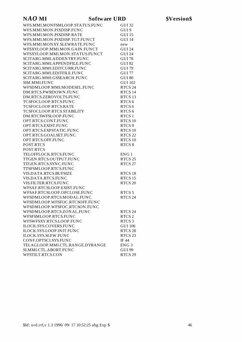
NAO MI Software URD $Version$
$Id: urd.rtf,v 1.3 1996/09/17 10:52:25 abg Exp $ 46
WFS.MMI.MONFSMLOOP.STATUS.FUNC GUI 32 WFS.MMI.MON.PIXDISP.FUNC GUI 9 WFS.MMI.MON.PIXDISP.RATE GUI 15 WFS.MMI.MON.PIXDISP.TGT.FUNCT GUI 14 WFS.MMI.MONXY.SLEWRATE.FUNC new WFSXYLOOP.MMI.MON.GAIN.FUNCT GUI 24 WFSXYLOOP.MMI.MON.STATUS.FUNCT GUI 24 SCITARG.MMI.ADDENTRY.FUNC GUI 78 SCITARG.MMI.APPENDFILE.FUNC GUI 82 SCITARG.MMI.EDITCURR.FUNC GUI 79 SCITARG.MMI.EDITFILE.FUNC GUI 77 SCITARG.MMI.GSSEARCH.FUNC GUI 80 SIM.MMI.FUNC GUI 102 WFSDMLOOP.MMI.MODESEL.FUNC RTCS 24 DM.RTCS.PWRDOWN.FUNC RTCS 14 DM.RTCS.ZEROVOLTS.FUNC RTCS 13 TCSFOCLOOP.RTCS.FUNC RTCS 6 TCSFOCLOOP.RTCS.RATE RTCS 6 TCSFOCLOOP.RTCS.STABILITY RTCS 6 DM.RTCSWFSLOOP.FUNC RTCS 1 OPT.RTCS.CONT.FUNC RTCS 10 OPT.RTCS.EXIST.FUNC RTCS 9 OPT.RTCS.EXPSTATIC.FUNC RTCS 10 OPT.RTCS.GOALSET.FUNC RTCS 22 OPT.RTCS.OFF.FUNC RTCS 10 POST.RTCS RTCS 8 POST.RTCS TELOFFLOCK.RTCS.FUNC ENG 1 TTGEN.RTCS.OUTPUT.FUNC RTCS 25 TTGEN.RTCS.SYNC.FUNC RTCS 27 TTSFSMLOOP.RTCS.FUNC VIS.DATA.RTCS.BUFSIZE RTCS 18 VIS.DATA.RTCS.FUNC RTCS 15 VIS.FILTER.RTCS.FUNC RTCS 20 WFSAF.RTCSLOOP.EXIST.FUNC WFSAF.RTCSLOOP.OPCLOSE.FUNC RTCS 5 WFSDMLOOP.RTCS.MODAL.FUNC RTCS 24 WFSDMLOOP.WFSFOC.RTCSOFF.FUNC WFSDMLOOP.WFSFOC.RTCSON.FUNC WFSDMLOOP.RTCS.ZONAL.FUNC RTCS 24 WFSFSMLOOP.RTCS.FUNC RTCS 2 WFSWFSXY.RTCS.LOOP.FUNC RTCS 3 ILOCK.SYS.COVERS.FUNC GUI 106 ILOCK.SYS.LOOP.INIT.FUNC RTCS 28 ILOCK.SYS.SLEW.FUNC RTCS 23 CONF.OPTSCI.SYS.FUNC IF 44 TELAGLOOP.MMI.CTL.RANGE.DYRANGE ENG 3 SI.MMI.CTL.ABORT.FUNC GUI 99 WFSTILT.RTCS.CON RTCS 29