napco netlink nl-mod-ul - alarmhow.net nl-mod-ul...the napco netlink™ nl-mod-ul is a device that...
TRANSCRIPT

1
R
333 Bayview Avenue Amityville, New York 11701
For Sales and Repairs, (800) 645-9445 For Technical Service, (800) 645-9440
Publicly traded on NASDAQ Symbol: NSSC
© NAPCO 2006 WI1523 6/06
GENERAL DESCRIPTION The NAPCO NetLink™ NL-MOD-UL is a device that allows the reporting of alarms over a TCP/IP based (Intranet or Inter-net) network. Alarm reporting, previously performed via Telco only, can now be performed over both a TCP/IP network and/or Telco, or via the TCP/IP network as a backup. The NL-MOD-UL is housed in a separate plastic enclosure, and is connected to the Local Download receptacle for the GEM-P816 / P1632 / P1664 / P3200 / P9600 and X255 Napco con-trol panels, and is connected via the parallel inputs with the MA3000 and other file alarm control panels. The NL-MOD-UL is compatible with the following NAPCO control panels:
GEM-P816 (version 30 or greater) GEM-P1632 (version 30 or greater) GEM-P1664 (version 30 or greater) GEM-P3200 (version 56 or greater) GEM-P9600 (version 56 or greater) GEM-X255 (version 56 or greater)
Not all control panels can be updated by replacing the existing firmware. The following is a list of minimum existing firmware:
GEM-P816 (version 30 or greater) GEM-P1632 (version 30 or greater) GEM-P1664: (version 30 or greater) GEM-P3200: (version 20 or greater) GEM-P9600: (version 20 or greater) GEM-X255: (version 4 or greater)
The NL-MOD-UL is supported by PCD-Windows Quickloader download software version 5.4 or greater. For the panels listed above, the Quickloader software will support download-ing through the Internet or an intranet, as well as the upload-ing of logs and other data.
The NL-MOD-UL includes a small transient protection device (named the NL-ULBD) inside its enclosure. In addition, the NL-MOD-UL is one part of a larger system which includes a software package to allow its configuration before use (the NL-MODCONFIG) and a rack-mountable Receiver (the NL-RCV-RMPCUL) to allow the receipt of alarms, status and su-pervisory data. A short description of each is provided below:
NL-MODCONFIG Software (version 2.0 or greater): NL-MODCONFIG is a software program allowing the con-figuration of the NL-MOD-UL with appropriate information (such as the static IP address of the module, static IP ad-dress of the NL-RCV-RMPCUL Receiver, etc.). The NL-MODCONFIG software is run on a PC (see System Re-quirements) and connects to the NL-MOD-UL via its net-work connection. In addition, NL-MODCONFIG allows the updating of the NL-MOD-UL firmware. Note: The NL-MODCONFIG software and its database should be re-tained if future access is necessary. For more information, see WI1243.
Central Station Receiver (NL-RCV-RMPCUL) The NAPCO Net.Link™ NL-RCV-RMPCUL (Receiver) is a fully UL compliant central station receiver platform. This Receiver is rack-mountable in a standard 4U configuration. The NL-RCV-RMPCUL (Receiver) can supervise each NL-MOD-UL, receive alarms, provide a means of maintaining accounts and provide a means of displaying alarms and event history (opening/closing, etc.). For more information, see the NL-RCV-RMPCUL Installation and programming manual, WI1491.
Transient Protection (NL-ULBD) The NL-MOD-UL includes electromagnetic protection and meets direct and indirect ESD requirements for Information Technology Equipment (ITE), however, burglary applica-tions may call for better protection. The NL-ULBD is a small device which gives added tran-sient protection and mounts entirely inside the NL-MOD-UL housing. The NL-ULBD protects the NL-MOD-UL from significantly larger transients and surges which may ema-nate from the network cable or associated devices. It is connected in series between the Ethernet cable that pro-vides network access and the RJ45 connector in the NL-MOD-UL. The NL-ULBD is required for UL compliant in-stallations.
SPECIFICATIONS Dimensions: 1½" x 7" x 4¾" (H x W x D) Input Voltage: Regulated 12VDC. Input Current: Nominal current (@12VDC) = 85mA. Note:
12V power must be supplied from a power limited auxil-iary power circuit on the control panel. Available panel combined auxiliary current is reduced by 85mA.
Outputs are PGM-style open collector (negative trigger) with a maximum sink current of 50mA.
NAPCO NetLink NL-MOD-UL
Network Communication Module
INSTALLATION INSTRUCTIONS
™
TABLE OF CONTENTS GENERAL DESCRIPTION ..........................................................................................1 SPECIFICATIONS .......................................................................................................1 MAXIMUM WIRE LENGTH .........................................................................................2 SYSTEM REQUIREMENTS ........................................................................................2 INSTALLATION INSTRUCTIONS GEM-P3200/P9600/X255 ....................................2 KEYPAD PROGRAMMING ........................................................................................3 LOAD FACTORY DEFAULTS .....................................................................................4 INSTALLATION INSTRUCTIONS GEM-P816/P1632/P1664 ....................................4 INSTALLATION INSTRUCTIONS GENERIC PANELS .............................................6 INSTALLATION INSTRUCTIONS FIRE CONTROL PANELS ..................................7 INPUT SETUP .............................................................................................................8 NL-MOD-UL CONFIGURATION OVERVIEW ............................................................9 DETAILED NL-MOD-UL CONNECTIONS ................................................................10 WIRING DIAGRAM ....................................................................................................11 WARRANTEE ............................................................................................................12
2
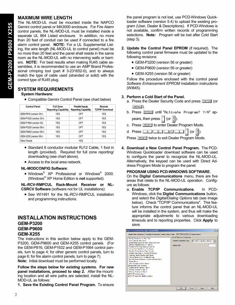
MAXIMUM WIRE LENGTH The NL-MOD-UL must be mounted inside the NAPCO Gemini control panel or MA3000 enclosure. For Fire Alarm control panels, the NL-MOD-UL must be installed inside a separate UL 864 Listed enclosure. In addition, no more than 20 feet of conduit can be used if connected to a fire alarm control panel. NOTE: For a UL Supplemental List-ing, the wire length (NL-MOD-UL to control panel) must be no more than 20 feet and the panel shall reside in the same room as the NL-MOD-UL with no intervening walls or barri-ers. NOTE: For best results when making RJ45 cable as-semblies, it is recommended to use an AMP Brand Profes-sional crimping tool (part # 3-231652-0), and to always match the type of cable used (stranded or solid) with the correct type of RJ45 plug. SYSTEM REQUIREMENTS
System Hardware: • Compatible Gemini Control Panel (see chart below)
• Standard 6 conductor modular RJ12 Cable, 1 foot in length (provided). Required for full zone reporting/downloading (see chart above).
• Access to the local area network.
NL-MODCONFIG Software: • Windows® XP Professional or Windows® 2000.
(Windows® XP Home Edition is not supported).
NL-RCV-RMPCUL Rack-Mount Receiver or NL-CSRCV Software (software not for UL installations): • See WI1491 for the NL-RCV-RMPCUL installation
and programming instructions. INSTALLATION INSTRUCTIONS GEM-P3200 GEM-P9600 GEM-X255 The instructions in this section below apply to the GEM-P3200, GEM-P9600 and GEM-X255 control panels. (For the GEM-P816, GEM-P1632 and GEM-P1664 control pan-els, turn to page 4; for other generic control panels, turn to page 6; for fire alarm control panels, turn to page 7). Note: Initial download must be performed locally.
Follow the steps below for existing systems. For new panel installations, proceed to step 2. After the mount-ing location and all wire paths are selected, install the NL-MOD-UL as follows: 1. Save the Existing Control Panel Program. To ensure
the panel program is not lost, use PCD-Windows Quick-loader software (version 5.4) to upload the existing pro-gram (User, Dealer & Descriptions). If PCD-Windows is not available, confirm written records of programming selections. Note: Program will be lost after Cold Start (step 3).
2. Update the Control Panel EPROM (if required). The
following control panel firmware must be updated to the following revisions:
• GEM-P3200 (version 56 or greater) • GEM-P9600 (version 56 or greater) • GEM-X255 (version 56 or greater)
Follow the procedure enclosed with the control panel Software Enhancement EPROM installation instructions (WI845).
3. Perform a Cold Start of the Panel.
a. Press the Dealer Security Code and press A (or R).
b. Press B until "Activate Program? Y/N" ap-
pears, then press D (or U). c. Press C to enter Dealer Program Mode.
d. Press 4093D (or U). Press C twice to exit Dealer Program Mode.
4. Download a New Control Panel Program. The PCD-
Windows Quickloader download software can be used to configure the panel to recognize the NL-MOD-UL. Alternatively, the keypad can be used with Direct Ad-dress Program Mode to program the panel.
PROGRAM USING PCD-WINDOWS SOFTWARE. On the Digital Communications menu, there are five
areas that relate to the NL-MOD-UL operation. Config-ure as follows: a. Enable TCP/IP Communications. In PCD-
Windows, click the Digital Communications button, and select the Digital/Dialing Options tab (see image below). Check "TCP/IP Communications". This fea-ture informs the control panel that an NL-MOD-UL will be installed in the system, and thus will make the appropriate adjustments to various downloading timeouts and to reporting properties. Click Apply to save.
GEM
-P32
00 /
P960
0 / X
255
Control Panel Full Zone Reporting Capability
Parallel Inputs Reporting Capability
Remote TCP/IP Download
GEM-P816 (version 30+) YES OPT YES GEM-P1632 (version 30+) YES OPT YES GEM-P1664 (version 30) YES OPT YES GEM-P3200 (version 56+) YES OPT YES GEM-P9600 (version 56+) YES OPT YES GEM-X255 (version 56+) YES OPT YES Other Panels YES

3
b. Enable Report to AES-TCP/IP. Select the Central Station Receivers tab (see image below). For each telephone number desired, check "Report to TCP/IP Receiver or AES" to enable the panel to report
alarms via the NL-MOD-UL accessory. Note: All parameters apply as they normally would for Telco reporting. For backup reporting Telephone No. 2 should be enabled. Click Apply and OK to save.
c. Enable Handshake Local Telemetry (Optional). In the Digital Communications Options tab (see previ-ous image), check "Handshake Local Telemetry". This enables the panel to wait for a transmission ac-knowledgment from the NL-RCV-RMPCUL Re-ceiver. (If the acknowledgment fails to occur within the allotted time, that control panel will generate a "Telemetry Failure" system trouble). Click Apply to save. Note: The NL-MOD-UL can queue up to 50 alarms and will continuously attempt to transmit the alarm to the NL-RCV-RMPCUL Receiver.
d. Enable TCP/IP Panel/Site Functions (Optional). In
the same Digital Communications Options tab, check "TCP/IP Panel/Site Initiated Functions" to enable the panel to connect via TCP (rather than dialup) for Auto Event Log Dumps, AutoDL ID, Function 6 and Site Initiated PCPreset connections. Click Apply to save.
e. Enable Callback Select and Options (Optional).
Click the Panel Selection button, and select the
Download / Callback Info tab (see image above). The Callback Select and Options radio buttons for Callback #1 or #2 will cause PCPreset IP address #1 or PCPreset IP address #2 to be used, respectively. Therefore, when "TCP/IP Panel/Site Initiated Func-tions" (see "d" above) is selected, the NL-MOD-UL will try to connect to a PCPreset computer using an IP address determined by the Callback # selection. Click OK to save.
Download to Control Panel. Before proceeding, save the information (File, Save Work). On the toolbar, click either the Local or Remote Communications buttons. Note: The TCP/IP Communications button can be se-lected only after the initial panel download. In addition, the panel download cannot be performed via TCP/IP until the NL-MOD-UL itself is programmed by the NL-MODCONFIG software.
In the Select Transfer Operation area, click the Download to Panel radio button. Check User Program Area, Dealer Program Area and Description Area. Click OK to initiate the data transfer to the control panel. In UL installations, disable remote downloading (UL does not allow unattended downloading) and after changing the program, always verify panel operation at the panel site.
PROGRAM USING THE KEYPAD Instead of using PCD-Windows Quickloader download
software to program the panel, access the control panel directly through the keypad as detailed below. See pre-vious descriptions for each address.
a. Enable "TCP/IP Communications" via address 2423, option 3 (press 3 on the keypad).
b. Enable "Handshake for Local Telemetry" via address 1027, option 8 (press 8 on the keypad).
c. Enable "TCP/IP Panel/Site Initiated Functions" via address 2423, option 4 (press 4 on the keypad).
d. For each telephone number desired, enable "Report to TCP/IP Receiver or AES" via addresses 0526 (option 7), 0551 (option 7) and 0576 (option 7) for Telco 1, Telco 2 and Telco 3 respectively.
e. Enable "Callback Select Options" via address 1022. Press either "1" for Callback Telephone Number 1 or "2" for Callback Telephone Number 2.
GEM
-P3200 / P9600 / X255

4
4. Mount NL-MOD-UL. Remove power to panel. The NL-MOD-UL must be mounted inside the NAPCO Gemini control panel enclosure. NOTE: For a UL Supplemental Listing, the wire length (NL-MOD-UL to the control panel) must be no more than 20 feet and the control panel shall reside in the same room as the NL-MOD-UL with no intervening walls or barriers.
Mount using the mounting flanges on both sides of the NL-MOD-UL enclosure using the screws appropriate for the location.
5. NL-MOD-UL Jumper. Make sure jumper JP2 is in-
stalled for normal operation. Refer to "Load Factory De-faults" below for JP2 operation.
6. NL-MOD-UL Wiring and Connections. Refer to the
wiring diagram. a. Insert the LAN Ethernet connector (RJ45 style) into
the receptacle marked "Ethernet" on the NL-MOD-UL circuit board. Insert the other end into the local network connector.
b. Insert the 6-conductor modular cable (supplied) into J1 (RJ12 style) of the control panel. Insert the other end into the "LOCAL DNLD" receptacle (RJ12 style) on the NL-MOD-UL circuit board.
c. Connect the panel Aux Power terminals 13 (+) and 14 (–) to the NL-MOD-UL terminals 1 (+) and 2 (–). See wiring diagram on page 11.
7. Power Up NL-MOD-UL. Upon applying power, the
DS1 LED on the NL-MOD-UL will turn on and remain on during the NL-MOD-UL startup sequence (duration is approximately 15 seconds). The LED will turn off for up to 20 seconds while the NL-MOD-UL verifies its configu-ration. The LED will then flash continuously indicating the unit has not been programmed. Note: Once the unit has been programmed with an acceptable program, the DS1 LED will flash for 1 second and not continu-ously. After the power up sequence ends and normal operation begins, the LED will turn on only when the NL-MOD-UL is communicating over the network.
8. Program the NL-MOD-UL with NL-MODCONFIG.
The NL-MODCONFIG software is used to program the NL-MOD-UL. Before using the NL-MODCONFIG soft-ware, obtain a static IP address, subnet mask and gate-way that will be dedicated to network communication. This information can be obtained from your network ad-ministrator. In addition, the Receiver static IP address must be obtained from the monitoring center.
Install the NL-MODCONFIG software on a PC (see Sys-tem Requirements on page 2). Then use NL-MODCONFIG to program the NL-MOD-UL.
Use one of two methods:
a. Connect to the NL-MOD-UL through the LAN. b. Use a laptop or a PC connected to a network cross-
over cable (not supplied).
Be sure to have the IP address, subnet mask and gate-way address. See WI1243 for more information regard-ing programming with the NL-MODCONFIG software.
Refer to the parallel Input Setup section on page 8 for more information.
9. Test Installation. Test the system by sending a Digital
Dialer Test report out through the LAN (Ethernet) into the NL-RCV-RMPCUL Receiver. Note: The NL-MOD-UL will attempt to send check-in signals immediately af-ter the unit is configured with NL-MODCONFIG soft-ware. Therefore, if the NL-MODCONFIG programming was performed via a crossover cable, then the control panel will indicate a System Trouble E25 within two min-utes of NL-MOD-UL programming.
INSTALLATION INSTRUCTIONS GEM-P816 GEM-P1632 GEM-P1664 The instructions in this section below apply to the GEM-P816, GEM-P1632 and GEM-P1664 control panels. (For the GEM-P3200, GEM-P9600 and GEM-X255 control pan-els, turn to page 2; for other generic control panels, turn to page 6; for fire alarm control panels, turn to page 7). Note: Initial download must be performed locally. Follow the steps below for existing systems. For new panel installations, proceed to step 2. After the mount-ing location and all wire paths are selected, install the NL-MOD-UL as follows: 1. Save the Existing Control Panel Program. To ensure
the panel program is not lost, use PCD-Windows Quick-loader software (version 5.4) to upload the existing pro-gram (User, Dealer & Descriptions). If PCD-Windows is not available, confirm written records of programming selections. Note: Program will be lost after Cold Start (step 3).
GEM
-P32
00 /
P960
0 / X
255
LOAD FACTORY DEFAULTS (Erase) (if needed) "Defaulting" the NL-MOD-UL will return it to its origi-
nal "out of box" condition. Default the NL-MOD-UL as follows:
1. Remove power from the NL-MOD-UL device. 2. Remove jumper JP2 3. Re-apply power. After about 40 seconds, the
NL-MOD-UL will flash the LED continuously indi-cating the default configuration has been loaded.
4. Upon continuous flashing of the LED, replace jumper JP2.
Once the NL-MOD-UL has been re-programmed using the NL-MODCONFIG software, the LED will flash once (for 1 second) upon powerup indicating the NL-MOD-UL has a valid configuration pro-grammed.
5
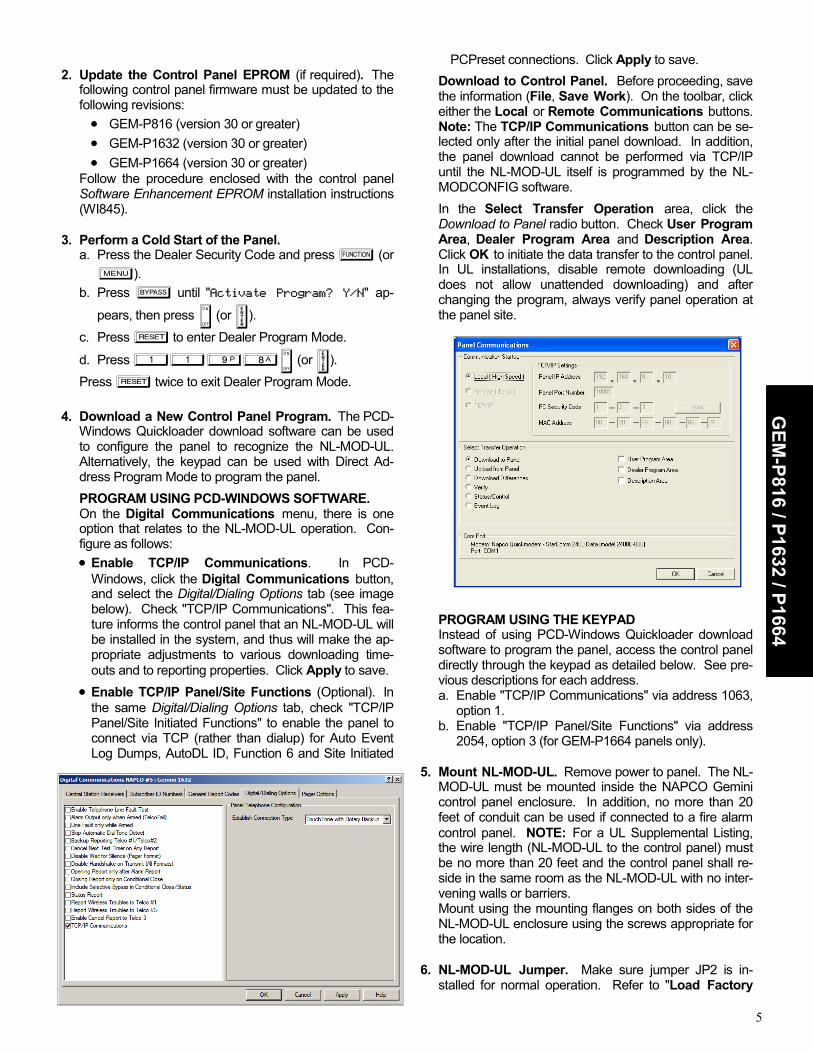
2. Update the Control Panel EPROM (if required). The
following control panel firmware must be updated to the following revisions: • GEM-P816 (version 30 or greater) • GEM-P1632 (version 30 or greater) • GEM-P1664 (version 30 or greater)
Follow the procedure enclosed with the control panel Software Enhancement EPROM installation instructions (WI845).
3. Perform a Cold Start of the Panel.
a. Press the Dealer Security Code and press A (or R).
b. Press B until "Activate Program? Y/N" ap-
pears, then press D (or U). c. Press C to enter Dealer Program Mode.
d. Press 1198D (or U). Press C twice to exit Dealer Program Mode.
4. Download a New Control Panel Program. The PCD-
Windows Quickloader download software can be used to configure the panel to recognize the NL-MOD-UL. Alternatively, the keypad can be used with Direct Ad-dress Program Mode to program the panel.
PROGRAM USING PCD-WINDOWS SOFTWARE. On the Digital Communications menu, there is one
option that relates to the NL-MOD-UL operation. Con-figure as follows: • Enable TCP/IP Communications. In PCD-
Windows, click the Digital Communications button, and select the Digital/Dialing Options tab (see image below). Check "TCP/IP Communications". This fea-ture informs the control panel that an NL-MOD-UL will be installed in the system, and thus will make the ap-propriate adjustments to various downloading time-outs and to reporting properties. Click Apply to save.
• Enable TCP/IP Panel/Site Functions (Optional). In the same Digital/Dialing Options tab, check "TCP/IP Panel/Site Initiated Functions" to enable the panel to connect via TCP (rather than dialup) for Auto Event Log Dumps, AutoDL ID, Function 6 and Site Initiated
PCPreset connections. Click Apply to save.
Download to Control Panel. Before proceeding, save the information (File, Save Work). On the toolbar, click either the Local or Remote Communications buttons. Note: The TCP/IP Communications button can be se-lected only after the initial panel download. In addition, the panel download cannot be performed via TCP/IP until the NL-MOD-UL itself is programmed by the NL-MODCONFIG software.
In the Select Transfer Operation area, click the Download to Panel radio button. Check User Program Area, Dealer Program Area and Description Area. Click OK to initiate the data transfer to the control panel. In UL installations, disable remote downloading (UL does not allow unattended downloading) and after changing the program, always verify panel operation at the panel site.
PROGRAM USING THE KEYPAD Instead of using PCD-Windows Quickloader download
software to program the panel, access the control panel directly through the keypad as detailed below. See pre-vious descriptions for each address. a. Enable "TCP/IP Communications" via address 1063,
option 1. b. Enable "TCP/IP Panel/Site Functions" via address
2054, option 3 (for GEM-P1664 panels only). 5. Mount NL-MOD-UL. Remove power to panel. The NL-
MOD-UL must be mounted inside the NAPCO Gemini control panel enclosure. In addition, no more than 20 feet of conduit can be used if connected to a fire alarm control panel. NOTE: For a UL Supplemental Listing, the wire length (NL-MOD-UL to the control panel) must be no more than 20 feet and the control panel shall re-side in the same room as the NL-MOD-UL with no inter-vening walls or barriers.
Mount using the mounting flanges on both sides of the NL-MOD-UL enclosure using the screws appropriate for the location.
6. NL-MOD-UL Jumper. Make sure jumper JP2 is in-
stalled for normal operation. Refer to "Load Factory
GEM
-P816 / P1632 / P1664

6
Defaults" on page 4 for JP2 operation. 7. NL-MOD-UL Wiring and Connections. Refer to the
wiring diagram. a. Insert the LAN Ethernet connector (RJ45 style) into
the receptacle marked "Ethernet" on the NL-MOD-UL circuit board. Insert the other end into the local network connector.
b. Insert the 6-conductor modular cable (supplied) into J1 (RJ12 style) of the control panel. Insert the other end into the "LOCAL DNLD" receptacle (RJ12 style) on the NL-MOD-UL circuit board.
c. Connect the panel Aux Power terminals 5 (+) and 6 (–) to the NL-MOD-UL terminals 1 (+) and 2 (–). See wiring diagram on page 11.
8. Power Up NL-MOD-UL. Upon applying power, the
DS1 LED on the NL-MOD-UL will turn on and remain on during the NL-MOD-UL startup sequence (duration is approximately 15 seconds). The LED will turn off for up to 20 seconds while the NL-MOD-UL verifies its configu-ration. The LED will then flash continuously indicating the unit has not been programmed. Note: Once the unit has been programmed with an acceptable program, the DS1 LED will flash for 1 second and not continu-ously. After the power up sequence ends and normal operation begins, the LED will turn on only when the NL-MOD-UL is communicating over the network.
9. Program the NL-MOD-UL with NL-MODCONFIG.
The NL-MODCONFIG software is used to program the NL-MOD-UL. Before using the NL-MODCONFIG soft-ware, obtain a static IP address, subnet mask and gate-way that will be dedicated to network communication. This information can be obtained from your network ad-ministrator. In addition, the Receiver static IP address must be obtained from the monitoring center.
Install the NL-MODCONFIG software on a PC (see Sys-tem Requirements on page 2). Then use NL-MODCONFIG to program the NL-MOD-UL.
Use one of two methods:
a. Connect to the NL-MOD-UL through the LAN. b. Use a laptop or a PC connected to a network cross-
over cable (not supplied).
Be sure to have the IP address, subnet mask and gate-way address. See WI1243 for more information regard-ing programming with the NL-MODCONFIG software.
Refer to the parallel Input Setup section on page 8 for more information.
10. Test Installation. Test the system by sending a Digital
Dialer Test report out through the LAN (Ethernet) into the NL-RCV-RMPCUL Receiver. Note: The NL-MOD-UL will attempt to send check-in signals immediately af-ter the unit is configured with NL-MODCONFIG soft-ware. Therefore, if the NL-MODCONFIG programming was performed via a crossover cable, then the control panel will indicate a System Trouble E25 within two min-utes of NL-MOD-UL programming.
INSTALLATION INSTRUCTIONS OTHER GENERIC PANELS The instructions in this section below apply to other generic control panels. (For the GEM-P3200, GEM-P9600 and GEM-X255 panels, turn to page 2; for the GEM-P816, GEM-P1632 and GEM-P1664 panels, turn to page 4). After the mounting location and all wire paths are selected,
install the NL-MOD-UL as follows: 1. Mount NL-MOD-UL. Remove power to panel. For a
UL Supplemental Listing for the panels, it is required that the NL-MOD-UL be installed in the same housing or in the same room as the control panel, with no interven-ing walls or barriers.
Mount using the mounting flanges on both sides of the NL-MOD-UL box using the screws appropriate for the location.
2. NL-MOD-UL Jumper. Make sure jumper JP2 is in-
stalled for normal operation. Refer to "Load Factory Defaults" on page 4 for JP2 operation.
3. NL-MOD-UL Wiring and Connections. Refer to the
wiring diagram. a. Insert the LAN Ethernet connector (RJ45 style) into
the receptacle marked "Ethernet" on the NL-MOD-UL circuit board. Insert the other end into the local network connector.
b. Connect the panel positive and negative Aux Power outputs to the NL-MOD-UL terminals 1 (+) and 2 (–) respectively. See wiring diagram on page 11.
The Supervisory Output (SUPV) will be active low if the NL-MOD-UL fails to check in with the NL-RCV-RMPCUL Receiver four consecutive times. Connect this output to a 24 hour supervisory zone in the control panel.
The Ringback Output (R.B.) will be active low for 2 sec-onds if the NL-MOD-UL receives an acknowledgement from the NL-RCV-RMPCUL Receiver after reporting a closing.
4. Power Up NL-MOD-UL. Upon applying power, the
DS1 LED on the NL-MOD-UL will turn on and remain on during the NL-MOD-UL startup sequence (duration is approximately 15 seconds). The LED will turn off for up to 20 seconds while the NL-MOD-UL verifies its configu-ration. The LED will then flash continuously indicating the unit has not been programmed. Note: Once the unit has been programmed with an acceptable program, the DS1 LED will flash for 1 second and not continu-ously. After the power up sequence ends and normal operation begins, the LED will turn on only when the NL-MOD-UL is communicating over the network.
5. Program the NL-MOD-UL with NL-MODCONFIG.
The NL-MODCONFIG software is used to program the NL-MOD-UL. Before using the NL-MODCONFIG soft-ware, obtain a static IP address, subnet mask and gate-way that will be dedicated to network communication.
GEN
ERIC
PA
NEL
S

7
This information can be obtained from your network ad-ministrator. In addition, the Receiver static IP address must be obtained from the monitoring center.
Install NL-MODCONFIG software on a PC (see System Requirements on page 2). Then use NL-MODCONFIG to program the NL-MOD-UL.
Use one of two methods:
a. Connect to the NL-MOD-UL through the LAN. b. Use a laptop or a PC connected to a network cross-
over cable (not supplied).
Be sure to have the IP address, subnet mask and gate-way address. See WI1243 for more information regard-ing programming with the NL-MODCONFIG software.
INSTALLATION INSTRUCTIONS FIRE ALARM CONTROL PANELS The instructions in this section below apply to generic fire alarm control panels. (For the GEM-P3200, GEM-P9600 and GEM-X255 panels, turn to page 2; for the GEM-P816, GEM-P1632 and GEM-P1664 panels, turn to page 4. For other (generic) control panels, turn to page 6). Note: The cable modem at the premises requires standby power, therefore a UL 1481 Listed UPS must be used at the premises to power the modem. In addition, the installa-tion must meet the requirements of NFPA 72. All external circuits must be electrically rated to permit proper installa-tion of this product using wiring methods permitted by the National Electrical Code, ANSI/NFPA 70. After the mounting location and all wire paths are selected, install the NL-MOD-UL as follows: 1. Mount NL-MOD-UL. Remove power to panel. The NL-
MOD-UL must be mounted in an adjacent UL 864 Listed enclosure, and no more than 20 feet of conduit can be used.
Mount using the mounting flanges on both sides of the NL-MOD-UL box using the screws appropriate for the location.
2. NL-MOD-UL Jumper. Make sure jumper JP2 is in-
stalled for normal operation. Refer to "Load Factory De-faults" on page 4 for JP2 operation.
3. NL-MOD-UL Wiring and Connections. Refer to the
wiring diagram.
a. Insert the LAN Ethernet connector (RJ45 style) into the receptacle marked "Ethernet" on the NL-MOD-UL circuit board. Insert the other end into the local network connector.
b. Connect the panel positive and negative Aux Power outputs to the NL-MOD-UL terminals 1 (+) and 2 (–) respectively. See wiring diagram on page 11.
c. Connect dry contacts into the parallel inputs. See parallel Input Setup on page 8 for more information.
d. Be sure fire alarm panel is programmed for delayed AC Fail Report for 1-3 hours.
The Supervisory Output (SUPV) will be active low if the
NL-MOD-UL fails to check in with the NL-RCV-RMPCUL four consecutive times. Connect this Supervi-sory Output to control an Air Products and Controls "PAM-4" relay. Wire the relay contact to a zone that can be programmed for a trouble or supervisory
4. Power Up NL-MOD-UL. Upon applying power, the
DS1 LED on the NL-MOD-UL will turn on and remain on during the NL-MOD-UL startup sequence (duration is approximately 15 seconds). The LED will turn off for up to 20 seconds while the NL-MOD-UL verifies its configu-ration. The LED will then flash continuously indicating the unit has not been programmed. Note: Once the unit has been programmed with an acceptable program, the DS1 LED will flash for 1 second and not continu-ously. After the power up sequence ends and normal operation begins, the LED will turn on only when the NL-MOD-UL is communicating over the network.
5. Program the NL-MOD-UL with NL-MODCONFIG.
The NL-MODCONFIG software is used to program the NL-MOD-UL. Before using the NL-MODCONFIG soft-ware, obtain a static IP address, subnet mask and gate-way that will be dedicated to network communication. This information can be obtained from your network ad-ministrator.
Install NL-MODCONFIG software on a PC (see System Requirements on page 2). Then use NL-MODCONFIG to program the NL-MOD-UL.
Use one of two methods:
a. Connect to the NL-MOD-UL through the LAN. b. Use a laptop or a PC connected to a network cross-
over cable (not supplied).
Be sure to have the IP address, subnet mask and gate-way address. See WI1243 for more information regard-ing programming with the NL-MODCONFIG software.
Refer to the parallel Input Setup section on page 8 for more information.
6. Test Installation. Test the system into the NL-RCV-
RMPCUL Receiver.
FIRE A
LAR
M PA
NELS
PAM-4 N/C Contacts
FACP EOLR
Supervisory Output (SUPV)
Trouble or Supervisory Zone
SUPV. (Terminal 9) +12V (Terminal 1)
NL-MOD-UL

8
OPT
ION
AL
INPU
TS
INPUT SETUP (IN0 - IN3) In the NL-MODCONFIG software, use the Optional
Input Setup button (located at the bottom of the NL-MODCONFIG main screen) to allow the configuration of four parallel inputs located on the NL-MOD-UL board terminal strip. In the Input Setup dialog, use the Input Type drop down to select as follows:
• If Active-low selected from the drop-down list, the input is considered normal if it is above the upper threshold ("High Limit") and faulted if it is below the lower threshold ("Low Limit"). An input value be-tween the lower and upper thresholds maintains the current state.
• If Active-high is selected from the drop-down list, the input is considered normal if it is below the lower threshold ("Low Limit") and faulted if it is above the upper threshold ("High Limit"). An input value be-tween the lower and upper thresholds maintains the current state. A 2.2k EOL resistor is needed. See diagram below.
• If EOLR is selected from the drop-down list, this en-ables the 2.2K EOL Resistor. The default input is in a normal state if the input is between the lower thresh-old ("Low Limit") and the upper threshold ("High Limit"). If not between these two thresholds the input is considered faulted. If EOLR is selected, the values programmed are identical to the values used in the panel. For exam-ple, to install a panic button, connect between the NL-MOD-UL terminals 2 and 6. If button is normally closed, connect EOL resistor in series. If button is normally open, then connect EOL resistor in parallel. See diagrams below.
Note: For advanced users, the upper and lower voltage limits can be programmed into the NL-MOD-UL. To en-able these settings to be changed, check Edit Thresh-olds.
Do NOT check Edit Thresholds for Fire Installa-tions.
• If Disabled is selected from the drop-down list, the
input is disabled and will not respond to any input voltage. The Optional Inputs (IN1, IN2 and IN3 on the NL-MOD-UL terminal strip) are configured with the lower limits set to zero and the upper limits set to 255. This results in all the Optional Inputs being nor-mal (i.e. "non-activated") regardless of the actual in-put voltage.
Reporting Code Select a Contact ID Code (E130 =Burglary, E110 =
Fire, etc.) to be displayed by the Receiver or the auto-mation system.
Note: If E301 A.C. Trouble is selected for input IN3, and the IN3 input is tripped, reporting for this input will be delayed 2 hours (if the input opens before the 2 hour delay ends, the E301 A.C. Trouble report will not be sent). If E301 A.C. Trouble is selected for the other inputs (IN0-IN2) the report is sent immediately.
Zone # Assign a Zone number to the input.
Area # Assign the input to an area number.
Status Type Select the status category to be assigned to the zone
when the NL-MOD-UL reports a status to the Receiver. The Receiver Service Application Panel Status screen displays the attribute selected here, including Check-In Status.
Note: If Fire Trouble is selected for any input, the NL-MOD-UL will retransmit the reporting code signal every 24 hours as long the associated input remains tripped.
Active high Example: N/O Relay Contact
6
2 GND (–)
IN1 (+)
2.2K
+12V
Panel Replay N/O
+12V
A/D
Example: Select EOLR in the I/O Setup Screen
N/C Panic Switch in Series
6
2 GND (–)
IN1 (+)
2.2K
N/O Panic Switch in Parallel
6
2
2.2K
GND (–)
IN1 (+)

9
NL-MOD-UL Configuration Overview
Wide Area Network RJ-45
RO
UTE
R
RJ-45
PCD-Windows Quickloader Download Software
PCD Windows
Internet
Control Panel
NL-MOD-UL
RO
UTE
R
(See next page for connections for each
control panel)
NL-CSRCV Software (Windows XP-Pro)
RJ-45
NL-CSRCV
RO
UTE
R
Central Station Receiver
Internet
NL-RCV-RMPCUL Rack Mounted (UL Listed for Commercial
Fire and Burglary)
RJ-45
RO
UTE
R
Central Station Receiver
NL-RCV-RMPCUL Rack Mounted (UL Listed for Commercial
Fire and Burglary)
RJ-45
RO
UTE
R
Central Station Receiver
Windows is a registered trademark of the Microsoft Corporation. Other products, product names and services described in this manual are for identification purposes only and may be trademarks of their respective companies.

10
Loca
l DN
LD (
RJ1
2)
GN
D
12V
Terminal 1 +12V
Terminal 2 GND
Terminal 3 DATA
Terminal 4 BELL
Terminal 5 IN0
Terminal 6 IN1
Terminal 7 IN2
Terminal 8 IN3
Terminal 9 SUPV.
Terminal 10 R.B.
NL-MOD-UL
Ethernet (RJ45) ROUTER
Local DNLD (RJ12)
GN
D
12V
Terminal 1 +12V
Terminal 2 GND
Terminal 3 DATA
Terminal 4 BELL
Terminal 5 IN0
Terminal 6 IN1
Terminal 7 IN2
Terminal 8 IN3
Terminal 9 SUPV.
Terminal 10 R.B.
NL-MOD-UL
Ethernet (RJ45) ROUTER
Local DNLD (RJ12)
4 User
Defined Inputs*
FACP Control Panels
Pani
c
Bel
l
GN
D
12V
Terminal 1 +12V
Terminal 2 GND
Terminal 3 DATA
Terminal 4 BELL
Terminal 5 IN0
Terminal 6 IN1
Terminal 7 IN2
Terminal 8 IN3
Terminal 9 SUPV.
Terminal 10 R.B.
NL-MOD-UL
Ethernet (RJ45) ROUTER
Ringback
Supervisory
Local DNLD (RJ12)
3 User
Defined Inputs
Control Panels
Other Generic Panels
Detailed NL-MOD-UL Connections Control Panels
GEM-P816 GEM-P1632 GEM-P1664 GEM-P3200 GEM-P9600 GEM-X255
4 User
Defined Inputs
+12V
Air Products and Controls PAM-4 Relay N/C
Zone
EOLR
*See Reporting Code on page 8 for more information regarding IN3 reporting delays.

11
NL-MOD-UL WIRING DIAGRAM REFER TO WI1523
NL-MOD-UL Wiring Diagram Notes: 1. See table below for description of right and left Ethernet Connection LED Functions. 2. Normal operation requires this shunt connector to be placed on top of JP2. 3. See pages 4, 6 and 7 for DS1 LED operation. 4. Voltage Input: 12VDC Input Current: 85mA. 5. Rated Current: 6.5mA Rated Voltage: 12VDC.
TERMINAL NUMBER DESCRIPTION 1 Positive 12 Volts 2 Ground 3 Data (not currently used) 4 Bell 5 User Defined Parallel Input 0. Configured by the Optional Input Setup screen. 6 User Defined Parallel Input 1. Configured by the Optional Input Setup screen. 7 User Defined Parallel Input 2. Configured by the Optional Input Setup screen. 8 User Defined Parallel Input 3. Configured by the Optional Input Setup screen. 9 Supervisory (Active Low) 10 Ringback (Active Low)
NL-MOD-UL TERMINAL DESCRIPTIONS
LED
DS13
JP2
REMOVE TO LOAD
DEFAULTS2
LOCAL DNLD
RJ12 CABLE
DATA GND +12V4
1 2 3 4 5 6 7 8 9 10
BELL IN05 IN25 IN15 IN35 SUPV. R.B.
ETHERNET
RJ45 CABLE
LEFT LED1
RIGHT LED1
MA
C A
ddre
ss
(Exa
mpl
e:
00-
20-4
A-8
0-81
-8B
)
ETHERNET CONNECTION LED FUNCTIONS
LEFT LED RIGHT LED COLOR MEANING COLOR MEANING
OFF NO LINK OFF NO ACTIVITY
SOLID AMBER 10 MBPS MOMENTARY AMBER HALF DUPLEX
SOLID GREEN 100 MBPS MOMENTARY GREEN FULL DUPLEX
NL-ULBD See WI1256
RJ45 RJ45

12
NAPCO SECURITY SYSTEMS, INC. (NAPCO) war-rants its products to be free from manufacturing defects in materials and workmanship for thirty-six months fol-lowing the date of manufacture. NAPCO will, within said period, at its option, repair or replace any product failing to operate correctly without charge to the original pur-chaser or user.
This warranty shall not apply to any equipment, or
any part thereof, which has been repaired by others, im-properly installed, improperly used, abused, altered, damaged, subjected to acts of God, or on which any se-rial numbers have been altered, defaced or removed. Seller will not be responsible for any dismantling or rein-stallation charges.
THERE ARE NO WARRANTIES, EXPRESS OR IM-
PLIED, WHICH EXTEND BEYOND THE DESCRIP-TION ON THE FACE HEREOF. THERE IS NO EX-PRESS OR IMPLIED WARRANTY OF MERCHANT-ABILITY OR A WARRANTY OF FITNESS FOR A PAR-TICULAR PURPOSE. ADDITIONALLY, THIS WAR-RANTY IS IN LIEU OF ALL OTHER OBLIGATIONS OR LIABILITIES ON THE PART OF NAPCO.
Any action for breach of warranty, including but not
limited to any implied warranty of merchantability, must be brought within the six months following the end of the warranty period.
IN NO CASE SHALL NAPCO BE LIABLE TO ANY-
ONE FOR ANY CONSEQUENTIAL OR INCIDENTAL DAMAGES FOR BREACH OF THIS OR ANY OTHER WARRANTY, EXPRESS OR IMPLIED, EVEN IF THE LOSS OR DAMAGE IS CAUSED BY THE SELLER'S OWN NEGLIGENCE OR FAULT.
In case of defect, contact the security professional
who installed and maintains your security system. In or-der to exercise the warranty, the product must be re-turned by the security professional, shipping costs pre-paid and insured to NAPCO. After repair or replace-ment, NAPCO assumes the cost of returning products under warranty. NAPCO shall have no obligation under this warranty, or otherwise, if the product has been re-paired by others, improperly installed, improperly used, abused, altered, damaged, subjected to accident, nui-sance, flood, fire or acts of God, or on which any serial numbers have been altered, defaced or removed. NAPCO will not be responsible for any dismantling, re-assembly or reinstallation charges.
This warranty contains the entire warranty. It is the
sole warranty and any prior agreements or representa-tions, whether oral or written, are either merged herein or are expressly canceled. NAPCO neither assumes, nor authorizes any other person purporting to act on its
behalf to modify, to change, or to assume for it, any other warranty or liability concerning its products.
In no event shall NAPCO be liable for an amount in
excess of NAPCO's original selling price of the product, for any loss or damage, whether direct, indirect, inciden-tal, consequential, or otherwise arising out of any failure of the product. Seller's warranty, as hereinabove set forth, shall not be enlarged, diminished or affected by and no obligation or liability shall arise or grow out of Seller's rendering of technical advice or service in con-nection with Buyer's order of the goods furnished here-under.
NAPCO RECOMMENDS THAT THE ENTIRE SYS-
TEM BE COMPLETELY TESTED WEEKLY. Warning: Despite frequent testing, and due to, but
not limited to, any or all of the following: criminal tamper-ing, electrical or communications disruption, it is possible for the system to fail to perform as expected. NAPCO does not represent that the product/system may not be compromised or circumvented; or that the product or system will prevent any personal injury or property loss by burglary, robbery, fire or otherwise; nor that the prod-uct or system will in all cases provide adequate warning or protection. A properly installed and maintained alarm may only reduce risk of burglary, robbery, fire or other-wise but it is not insurance or a guarantee that these events will not occur. CONSEQUENTLY, SELLER SHALL HAVE NO LIABILITY FOR ANY PERSONAL IN-JURY, PROPERTY DAMAGE, OR OTHER LOSS BASED ON A CLAIM THE PRODUCT FAILED TO GIVE WARNING. Therefore, the installer should in turn advise the consumer to take any and all precautions for his or her safety including, but not limited to, fleeing the premises and calling police or fire department, in order to mitigate the possibilities of harm and/or damage.
NAPCO is not an insurer of either the property or
safety of the user's family or employees, and limits its liability for any loss or damage including incidental or consequential damages to NAPCO's original selling price of the product regardless of the cause of such loss or damage.
Some states do not allow limitations on how long an
implied warranty lasts or do not allow the exclusion or limitation of incidental or consequential damages, or dif-ferentiate in their treatment of limitations of liability for ordinary or gross negligence, so the above limitations or exclusions may not apply to you. This Warranty gives you specific legal rights and you may also have other rights which vary from state to state.
NAPCO LIMITED WARRANTY