nasa · pitch and yaw controls for hovering flight were provided by a ... equipped with an...
TRANSCRIPT

El
copy ;_6iNASA MEMO 10-27-58T,
.1
O
p_
<
<
NASA
MEMORANDUM
HOVERinG AND TRANSITION FLIGHT TESTS OF A I/5-SCALE
MODEL OF A JET-POWERED VERTICAL-ATTITUDE
VTOL RESEARCH AIRPLANE
By Charles C. Smith,
Langley Research Center
Langley Field_
(" L.ACSIFIE y. DOCUMH _IT
Tbl_ n_t_rlal _oatain.s _for,_latlor. affectln_T the Natior_l L_fense of the U_ltecl S_tes w
of l.he es_ion_ laws, Title I_, U.S._., ,_ecs, 7_3 and 7_4, the tr_m.smission or revelation of Whic_
marker to an u_'_uthorized person Is pro_bit_d by la,.v.
Jr.
_,_ .._D
NATIONAL AERONAUTICS ANDSPACE ADMINISTRATION
WASHI NGTON
https://ntrs.nasa.gov/search.jsp?R=19980227972 2020-04-07T11:52:37+00:00Z


IC
,vo
!
!
o
CONFIDENTIAL
NATIONAL AERONAUTICS AND SPACE ADMINISTRATION
MEMORANDUM I0-27-58L
HOVERING AND TRANSITION FLIGHT TESTS OF A I/5-SCALE
MODEL OF A JET-POWERED VERTICAL-ATTITUDE
VTOL RESEARCH AIRPLANE*
By Charles C. Smith, Jr.
SUMMARY
An experimental investigation has been made to determine the dynamic
stability and control characteristics of a i/5-scale flying model of a
jet-powered vertical-attitude VTOL research airplane in hovering and tran-
sition flight. The model was powered with either a hydrogen peroxide
rocket motor or a compressed-air jet exhausting through an ejector tube
to simulate the turbojet engine of the airplane. The gyroscopic effects
of the engine were simulated by a flywheel driven by compressed-air
jets. In hovering flight the model was controlled by jet-reaction
controls which consisted of a swiveling nozzle on the main jet and a
movable nozzle on each wing tip; and in forward flight the model was
controlled by elevons and a rudder.
If the gyroscopic effects of the jet engine were not represented,
the model could be flown satisfactorily in hovering flight without any
automatic stabilization devices. When the gyroscopic effects of the
jet engine were represented, however, the model could not be controlled
without the aid of artificial stabilizing devices because of the gyro-
scopic coupling of the yawing and pitching motions. The use of pitch
and yaw dampers made these motions completely stable and the model
could then be controlled very easily. In the transition flight tests,
which were performed only with the automatic pitch and yaw dampers
operating, it was found that the transition was very easy to perform
either with or without the engine gyroscopic effects simulated, although
the model had a tendency to fly in a rolled and sideslipped attitude at
angl@s of attack between approximately 25 ° and 45 ° because of static
directional instability in this range.
_Title, Unclassified.
CONFIDENTIAL

2 CONFIDENTIAL
INTRODUCTION
An investigation has been madeto determine the dynamic stabilityand control characteristics of a i/5-seale flying model of a jet-poweredvertical-attitude VTOLresearch airplane in hovering and transitionflight. The airplane has a modified triangular wing and a modifiedtriangular vertical tail mountedon top of t_e wing and has no horizon-tal tail. Take-offs and landings with the a_rplane in a vertical atti-tude are madefrom a horizontal wire with a special hook-on attachmenton the nose of the airplane. For convenience, however, the airplanealso had a tricycle landing gear to permit ccnventional take-offs fromand landings on the ground so that the initial transitions could beperformed at a safe altitude. Control for hovering flight is providedby jet-reaction controls which consist of a swiveling nozzle on themain jet for pitch and yaw control and of small nozzles utilizingengine-bleed air on the wing tip for roll control. Aerodynamic con-trols consisting of elevons and rudder are provided for control in nor-mal forward flight.
The present investigation consisted mainly of flight tests of themodel in take-offs and landings, hovering flight, and transition betweenhovering and unstalled forward flight. A few force tests were also madein the transition condition in order that the flight-test results mightbe better understood. The hovering flight tests consisted of unrestrainedhovering flights with and without artificial stabilization in pitch andy_w and with and without the gyroscopic force3 of the jet engine repre-sented. Take-offs and landings from a horizoatal wire were also made.The effects of rotating the swiveling nozzle to obtain a cross couplingof the pitch and yaw controls in an attempt t_ counteract the effect ofthe gyroscopic forces of the jet engine were llso determined. Thetransition flights were constant-altitude tra:_sitions and covered anangle-of-attack range from about 20° to 90° a_d a speed range of 0 toii0 knots (full scale). Both rapid and very _low transition flightswere made. The slow transitions were madein completely free flight inthe Langley full-scale tunnel, and the rapid _ransitions were madeonthe Langley control-line facility which uses _he control-line techniquein which the model is restrained in the later_l degrees of freedom buthas longitudinal freedom.
Almost all of the tests were conducted wlth hydrogen-peroxide-decomposition rockets used for power because _hat was the most practi-cal source of jet power for the model availabi_e at the time the investi-gation was started. Because of the danger to the facilities of firefrom spilled hydrogen peroxide, it was decided to conduct the initialtests outdoors until sufficient safety and e_ipment reliability wereproven to justify using the hydrogen peroxide for wind-tunnel or other
"O!
!
Oo
CONFIDENTIAL

CONFIDENTIAL 3
indoor tests. During the time that these initial flight tests were beingconducted and the hydrogen peroxide equipment was being developed, asupply of compressedair becameavailable for use in the full-scale tun-nel and the building containing the hovering test area which permittedthe model to be powered with compressed-air jets instead of hydrogenperoxide. The transition tests in the full-scale tunnel and the fewremaining hovering tests were therefore conducted with the modelpowered with compressedair.
The results of the flight investigation were obtained mainly fromthe observations madeby the pilots of the stability, controllability,and general flight behavior of the model. These results were supple-mented by motion-picture records of the flights.
NOMENCLATUREANDSYMBOLS
In order to avoid confusion in terminology which might arise becauseof the large range of operating attitudes of the model, it should benoted that the controls and motions of the model are referred to in con-ventional terms relative to the body system of axes; that is, the rudderon the vertical tail and the deflection of the jet to the left or rightby the swiveling nozzle produced yaw about the normal body axis, dif-ferential deflection of the elevons and the wing-tip nozzles producedroll about the fuselage axis, and simultaneous up or downdeflectionsof the elevons and deflection of the jet up or downby use of theswiveling nozzle produced pitch about the spanwise axis.
The symbols used are as follows:
meanaerodynamic chord
angle of bank about fuselage axis, deg
angle of sideslip, deg
C_ angle of attack of fuselage, deg
if fuselage incidence angle (angle between longitudinal fuselage
axis and relative wind), deg
V velocity, ft/sec
S wing area, sq ft
b wing span, ft
CONFIDENTIAL

4 CONFIDENTIAL
q
P
5 e
5a
Cn
C_
Cy
ItD
I X
I Z
pV 2
dynamic pressure T' lb/sq ft
mass density
simultaneous deflection of elevons_ deg
differential deflection of elevons, deg
yawing-moment coefficient referred to body axis, Yawin_ moment_b
rolling-moment coefficient referred!, to body axes,
Rolling moment
qSb
Side forceside-force coefficient referred to body axis,
qs
inertia of gyroscope about its spin axis multiplied by angular
velocity about its spin axis, lb-in.2/sec
moment of inertia about X-axis, sl1_-ft 2
moment of inertia about Y-axis, sl_g-ft 2
moment of inertia about Z-axis, slug-ft 2
APPARATUS AND TES_S
Model
Figures 1 and 2 are photographs of the _Lodel. In figure 2 the jet-
reaction controls can be seen. A sketch shoving some of the more impor-
tant dimensions is shown in figure 3. The g_ometric characteristics of
the model are presented in table I, and the _ss characteristics are
presented in table II.
The model was powered by either a 60-polnd-thrust hydrogen-peroxide-
decomposition rocket motor or compressed-air jets exhausting into an
ejector tube. Photographs of the power plani are presented in figures 4
and 9, and a sketch illustrating the install_tion of the power plant in
the model is presented in figure 6. The rocket motor or compressed-air
jet when installed in this manner acted as a jet pump to produce a flow
CONFIDENTIAL

CONFIDENTIAL 5
of air through the model. It is desirable to represent the internalair flow since previous tests with models having large inlets ahead ofthe center of gravity have shownthat the inlet air flow can haveappreciable effects on stability in hovering flight and since the inter-nal flow causes dampingmomentswhich might also have an importanteffect on stability in hovering flight. With the ejector system usedin the model, it waspossible to create an air flow of approximatelytwice the mass flow of the rocket and a thrust of 1.2 times that ofthe rocket. Under these conditions the inlet air flow was approximately80 percent, and the exit air flow 120 percent, of the scaled-down massflow of the full-scale airplane. The hydrogen peroxide was suppliedto the rocket motor by a special pressurizing system that is describedlater. No measurementswere madeof the induced mass flow with thecompressed-air jet used as the source of power. Analysis of the factorsinvolved, however, indicate that the inlet air flow was approximatelythe sameas that with the rocket used for power but that the exit massflow was about 200 percent of the scaled-down-engine mass flow.
The model had a modified delta-wing and a vertical-tail surface withconventional flap-type elevon and rudder controls for use in forwardflight. Pitch and yaw controls for hovering flight were provided by aswiveling nozzle at the end of the tail pipe which can be seen in fig-ure 5- Roll control wasprovided by two small hydrogen peroxide rocketmotors (or air jets), one on each wing tip, which were deflected dif-ferentially. The roll-control rockets are also evident in figure 5.
In most flights, the jet-reaction controls were operated by theflicker-type (full-on or off) pneumatic actuators generally used onmodels by the Langley free-flight tunnel section. These controls wereequipped with an integrating-type trimmer which trimmed the control asmall amount in the direction the control was movedeach time a controldeflection was applied. With actuators of this type, a model becomesaccurately trimmed after flying a short time in a given flight condition.In someof the flights an electric trim motor was used to take care oflarge changes in trim.
Artificial stabilization in pitch and yaw was used in someof theflights. The sensing elements were rate gyroscopes which, in responseto rate of pitch or yaw, provided signals to proportional controlactuators which movedthe main jet nozzle to oppose the pitching oryawing motion. A pilot-operated override was provided in the gyroscope-operated devices so that the pilot could have all the available controlat his command. The operation of these devices was such that theyprovided damping in pitch or yaw regardless of the attitude of the model.The override cut out the damping action and applied all available con-trol in the direction desired by the pilot.
CONFIDENTIAL

6 C0NFIDENTIAL
The model was initially equipped with a conventional tricycle-type landing gear, but this landing gear was later removed in the flighttests in order to avoid the fouling of the flight cable. For the take-off and landing tests a special hook similar to that on the full-scaleairplane was fastened to the nose.
The gyroscopic forces of the jet engine were simulated by a fly-wheel driven by air jets at speeds up to 45,000 rpm which gave a valueof I_ of 39,300 ib-in-2/sec, approximately the correct scaled-downvalue for the airplane.
Test Equipment and Se<_up
Transition flight tests with complete freedom were conducted inthe Langley full-scale tunnel. The take-off, landing, hovering, andrapid-transition flight tests were conducted on the Langley control-line facility. Additional hovering flight toasts were conducted in alarge building in connection with the prepar_tion of the model fortesting in the full-scale tunnel.
Figure 7 shows the test setup for the flight tests in the full-scale tunnel. The sketch shows the pitch pilot, the safety-cable oper-ator, and the power operator on a balcony at the side of the test sec-tion. The roll pilot was located in an enclc)sure in the lower rear partof the test section, and the yaw pilot was a'_ the top rear of the testsection. The pitch, roll, and yawpilots we_'elocated at the mostadvantageous points for observing and control.ling the particular phaseof the motion with which each was concerned. Motion-picture recordswere obtained with fixed camerasmounted nem' the pitch and yaw pilots.
The air for the main propulsion jets and for the jet controls wassupplied through flexible plastic hoses, whi;_ethe power for the electrictrim motors and control solenoids was suppli,_d through wires. These wiresand tubes were suspendedoverhead and taped _o a safety cable (I/16-inchbraided aircraft cable) from a point approx_mtely 15 feet above themodel downto the model. The safety cable, _hich was attached to thetop of the wing just ahead of the vertical t_il of the model, was usedto prevent crashes in the event of a power o:' control failure, or inthe event that the pilots lost control of th_ model. During flight thecable was kept slack so that it would not ap])reciably influence themotions of the model. For the cases in whiclL the model was powered withcompressedair instead of hydrogen peroxide, the hose required to supplysufficient compressedair to the model was cc,nsiderably larger than thatrequired for supplying hydrogen peroxide, bu_ its interference with themodel motions was considered to be within to[i.erable limits.
CONFIDENTIAL

CONFIDENTIAL 7
The test technique is best explained by the description of a typi-cal flight. The model hung from the safety cable, and the power wasincreased until the model was in steady hovering flight. At this point
the tunnel drive motors were turned on and the airspeed began to increase.
As the airspeed increased, the controls and power were operated so that
the model tilted progressively into the wind in order to maintain its
fore-and-aft position in the test section until a particular phase of
the stability and control characteristics was to be studied. Then the
pilots performed the maneuvers required for the particular tests and
observed the stability and control characteristics. The flight was
terminated by gradually taking up the slack in the safety cable while
reducing the power to the model.
This same testing technique was used for the hovering flight tests
except that the wind tunnel was not necessary. Some of these tests
were conducted indoors in a large open building, with the model powered
by compressed-air jets. Other hovering tests, with the model powered
with the hydrogen-peroxide rockets were conducted at the Langley control-
line facility with the crane boom serving as the overhead support for
the flight cable.
The control-line facility is illustrated in figure 8 and described
in detail in reference i. Basically the control-line facility consists
of a crane with a jib boom to provide an overhead support for the safety
cable. The pilot and operators ride in the cab of the crane so that
they will always face the model as it flies in a circle on the end of a
restraining line. With this facility, rapid transition flights from
hovering to normal forward flight can be made since the crane has a high
rate of acceleration. The facility is mounted on a pedestal in the
middle of a large concrete apron located in a wooded area which serges
as a wind break.
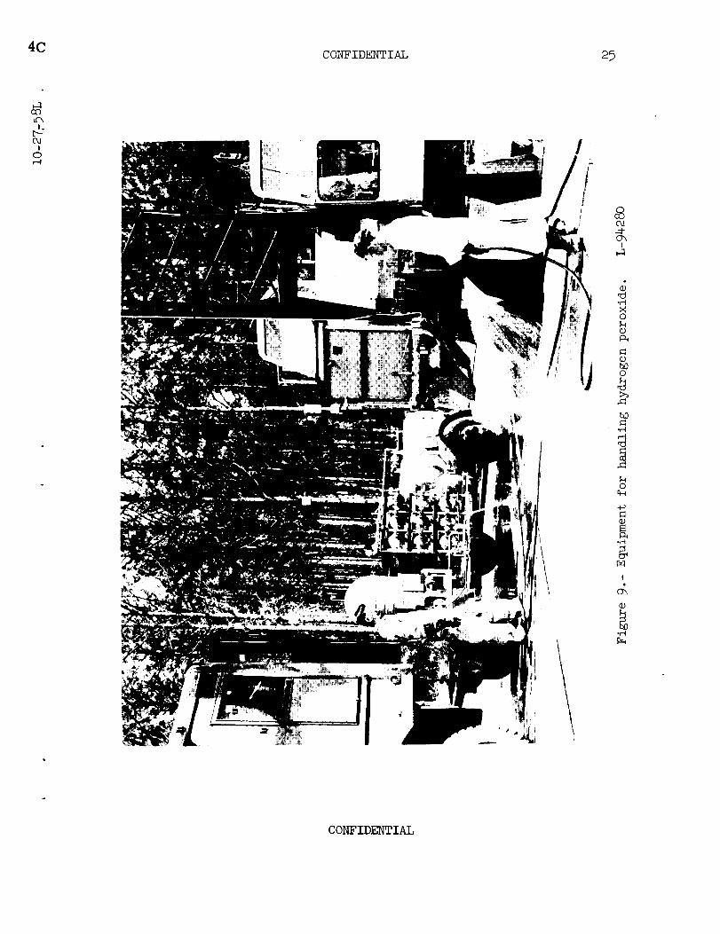
The equipment for handling the hydrogen peroxide consisted mainly
of two pieces: a system for pressurizing and controlling the flow of
the hydrogen peroxide, and a trailer with a tank for transporting the
hydrogen peroxide. This equipment is shown in figure 9. A simplified
sketch of a hydrogen peroxide pressurizing system is presented in
figure i0. The pressurizing system is enclosed in a cabinet and mounted
on the crane so that the power operator can ride inside the cab and
operate the necessary valves for operating the system and controlling
the thrust of the rocket motor in the model. The i/2-inch stainless
steel tubing mounted on the boom of the crane carries the hydrogen
peroxide from the pressurizing system to a remotely controlled safety
cutoff valve on the end of the jib boom. A i/4-inch flexible plastic
hose covered with a Dacron braid carries the hydrogen peroxide from the
end of the jib boom into the model.
CONFIDENTIAL

8 CONFIDENTIAL
Tests
The investigation consisted mostly of flight tests which were madein order to study the stability and control characteristics of the model.The stability and controllability were determined in various tests eitherqualitatively from the observations of the pilots or quantitatively frommotion-picture records of the flights.
Transition flight tests.- Flight tests were made in the test sec-
tion of the full-scale tunnel in order to determine the overall stabil-
ity and control characteristics of the model in transition flight from
hovering to level flight. Some of the flights were made with the fly-
wheel operating at one-half speed and some at full speed to determine
the effects of the jet-engine gyroscopic forces on the transition flight
behavior of the model.
These flights were slow constant-altitude transitions covering a
speed range from about O to 50 knots, which corresponds to full-scale
airspeeds of 0 to ii0 knots. Since small _ljustments or corrections
in the tunnel airspeed could not be made readily, the pitch pilot and
the power operator had to continually make _djustments in order to hold
the model in the center of the test section. Flights were also made
in which the airspeed was held constant at intermediate speeds so that
the stability and control characteristics at a particular speed could
be studied.
In order to study the stability and control characteristics of the
model in rapid transitions, flight tests were also made on the control-
line facility. This part of the investigation was limited to a study
of longitudinal stability and control since the model is restrained in
the lateral degrees of freedom by the contrDl line.
Hoverin6 fli6ht tests.- Hovering flight tests were made with the
model hovering at heights of 15 to 20 feet above the ground to determine
the basic stability and controllability of the model. These tests were
made both indoors in still air and outdoors in moderately rough air.
The same type of setup and techniques were used to fly the model in
both the indoor tests and the outdoor tests, with the exception that
compressed air was used for the indoor tests and hydrogen peroxide was
used for the outdoor tests. The tests included a study of the effect
of engine gyroscopic moments on the hoverin_ flight behavior of the
model with the flywheel running at full speed and one-half speed. In
order to determine whether a simple cross coupling of the controls
would effectively cancel the effect of the Eyroscopic precessional
moment of the jet engine for practical purposes, flights were made with
the hinge lines of the swiveling nozzle rotated various amounts about
CONFIDENTIAL

2C
_9W%!
OdI
o
CONFIDENTIAL 9
the fuselage axis. Tests were also made to determine the effects of
damping in pitch and yaw on the hovering flight behavior of the model
with and without the jet-engine gyroscopic forces represented.
Take-off and landin_ flight tests.- The take-offs from a horizon-
tal wire were made by rapidly increasing the thrust until the model had
climbed clear of the horizontal wire. The power operator then adjusted
the thrust for either hovering flight or a transition from hovering to
forward flight. For the landing tests the power operator first adjustedthe thrust so that the model would hover near the wire. Then the thrust
was reduced so that the model descended slowly and the pilot maneuvered
the model to engage the wire with the landing hook. At this point the
thrust was reduced as quickly as possible, and the model settled downon the wire.
Force tests.- Some preliminary force tests were made in the free-
flight tunnel in an effort to determine some of the stability and con-
trol characteristics of the model in transition flight. The tests
were made with power on by using compressed air to supply the necessary
thrust to balance the drag along the wind axis for the zero sideslip
condition.
RESULTS AND DISCUSSION
A motion-picture film supplement has been prepared and is availeble
on loan. A request card form and a description of the film will be
found at the back of this paper, on the page immediately preceding the
abstract and index pages.
Hover ing Flight
The model could be flown smoothly and easily in hovering flight
without the aid of any artificial stabilization when the gyroscopic
effects of the jet engine were not represented. The jet-reaction con-
trols provided good controllability, and the model could be moved fairly
rapidly from one position to another and restored quickly to a steady-
flight condition. The motions of the model in pitch and yaw were very
steady. Since the stability was not studied in detail, it is not known
whether the model had unstable pitching and yawing oscillations such
as had been experienced previously with propeller-driven models of the
vertical-attitude type of VTOL airplanes. (See, for example, ref. 2.)
It was clear, however, that the model did not tend to start an oscil-
lation as quickly as did the propeller-driven models and was, conse-
quently, easier for the pilots to fly. The rolling motions, as would
CONFIDENTIAL

i0 CONFIDENTIAL
be expected, seemedabout neutrally stable. These flights without theflywheel running to represent the engine gyros_opic effects were intendedto provide basic research information on a configuration of this typeof airplane. In this condition the model woull represent an airplanepowered by two or more oppositely rotating engines or by a split-compressor engine with oppositely rotating conpressor sections whichwould give a very low net gyroscopic effect.
Attempts to hover the model with the flywheel running at full speedto correctly simulate the gyroscopic effects of the jet engine of the
research airplane were unsuccessful because of the violent motion
resulting from the coupling of the yawing and pitching motions. The
pilots were unable to control the model for a_ly appreciable period of
time and considered it completely uncontrolla_le.
Cross coupling the pitch and yaw controls by rotating the gimbal
rings of the swiveling nozzle about the center line of the ejector tube
proved to be an unsuccessful method of reducing the troubles caused by
the gyroscopic cross coupling because the co_ling resulting from motions
other than those induced by the controls was not counteracted at all.
The flights generally started off well but s_on ended with the loss of
control of the model by the pilots. Of the angles obtained by rotating
the gimbal rings (from 0° to 45 ° clockwise, looking at the rear of the
model) angles between 15 ° and 30 ° seemed to be the best with the flywheel
rotating in a counterclockwise direction as viewed from the rear. Even
these angles, however, barely afforded any r_oticeable improvement in
the flight behavior of the model.
The use of pitch and yaw dampers greatly improved the hovering
flight behavior of the model both with and _ithout the gyroscopic
effects of the jet engine simulated. In fact, the pilots were able
to fly the model for long periods of time Jn still air without giving
any control, even with the gyroscopic effects of the jet engine fully
simulated.
The gyroscopic moments of a future ta:tical airplane of the general
type represented by the research airplane _ould be much less than those
of the research airplane itself because th_ tactical airplane would be
powered by an advanced afterburning engine of lower specific weight than
the relatively heavy nonafterburning engire used in the research airplane.
Flight tests were, therefore, made with t_e flywheel rotating at _ne-half
speed in order to represent approximately the gyroscopic moments of a
turbojet engine such as might be used in ;_tactical airplane of this
type. In these tests the model could be flown for short periods of time
without any artificial stabilization, but the flights generally ended
with the model getting out of control. Tae flights usually started with
the model flying fairly smoothly and bec_e progressively rougher as the
O|DO-W
k_
CONFIDENTIAL

CONFIDENTIAL ii
pilots gave corrective control or tried to maneuver the model. Thepilots described the flight behavior of the model as being similar tohovering in gusty air, with little or no damping in pitch and yaw inthat the model received repeated and unexpected disturbances about oneaxis as a result of motion about another axis.
Take-Offs and Landings
Take-offs from and landings on a horizontal wire were made on thecontrol-line facility, where the model is restrained in the lateraldegrees of freedom. These tests were madewithout artificial stabili-zation and without the gyroscopic effects of the jet engine simulated.Under these conditions take-offs and landings were easy to make. Sincein the hovering tests the model flew more smoothly with the yaw andpitch dampers operating, even with the gyroscopic forces of the jetengine simulated, it would be expected that the take-offs and landingswould be even easier to perform with the engine gyroscopic momentssimulated and with artificial stabilization; this condition more closelyapproximates the flight condition of the full-scale airplane.
Transition Flight
Longitudinal characteristics.- Transitions from hovering to nor_l
forward flight and back to hovering flight could be made smoothly and
easily in the full-scale tunnel, and the model seemed to have stability
of angle of attack over most of the speed range. At times the model
would fly "hands off" in pitch for reasonably long periods of time when
it was trimmed correctly and the airspeed was not being changed. These
flights in the full-scale tunnel represented slow, constant-altitude
transitions and covered a range of angles of attack from about 20 ° to 90 °.
For these tests the model was equipped with pitch and yaw dampers which
operated the swiveling nozzle. The design of the control system in the
model would not permit the jet-reaction pitch control to be switched
out of the pitch-control system, so the jet controls were used throughout
the transition. The elevons, however, could be switched in or out of the
pitch-control system at will. It was found that the swiveling nozzle
provided adequate pitch control throughout the transition, so the elevons
were not generally used for control although they were generally trimmed
up lO ° to provide most of the trim required when the model was in normal
forward flight at about a 20 ° angle of attack after the transition.
The model responded quickly to any adjustments in thrust and could
be flown very smoothly and steadily. There was, however, a large and
abrupt change in the thrust required for level flight between angles of
attack of about 20 ° and 45 ° . This observation is further substantiated
CONFIDENTIAL

12 CONFIDENTIAL
by the data of figure ii which shows a plot of thrust and angle of attackrequired for trimmed flight against forward sp_ed as computedfrom somepreliminary force-test data for a model weight of 40 pounds.
Additional flights were madeon the control-line facility to studythe longitudinal stability and control of the model in rapid constant-altitude transitions over a range of angles of attack from about 20°to 90° . The flight behavior of the model in the rapid transitions wasabout the sameas in the slow transitions in that the model was easy tocontrol in pitch by using the jet-reaction control. The elevons wereset to trim the model at an angle of attack of about 20° and were notused to control the model. Thrust control was somewhatmore difficultthan for the slow transitions because the mode_went more rapidly throughthe angle-of-attack range from 20° to 45° where the large changes occurredin the thrust required.
Lateral characteristics.- The lateral stability and control character-
istics of the model were generally satisfactory, and the transition could
be made smoothly and easily throughout the angle-of-attack range. As
pointed out previously, all of the transitions were made with a yaw
damper operating the main jet nozzle because, im the hovering tests_it was found that artificial damping was required to reduce the effects
of the engine gyroscopic moments. The model was not flown without the
dampers; therefore, no information was obtained on the behavior of an
airplane of the same general configuration but _ith counterrotating
engines or split-compressor engines with oppositely rotating compressor
seQtions which would give practically no net gyroscopic effects. The
behavior of a somewhat similar model under these conditions was reportedin reference 3, however, and showed that a cert_in amount of automatic
stabilization was very desirable in the transition range.
The one undesirable lateral stability char_cteristic of the model
was that at angles of attack between approximat_ly 25 ° to 45 ° the model
tended to fly in a rolled and sideslipped attit_le. This did not appear
to be a dangerous condition, and the pilot had no difficulty in keeping
the model in the center of the test section. I_z fact, the model would
fly "hands off" for long periods of time when the airspeed and angle of
attack were not being varied. The roll pilot fecund that a large amount
of roll control, approximately the maximum control available on the
airplane, was required to restore the model to zero bank once it had
gotten into this trimmed rolled and sideslipped attitude. Some prelimi-
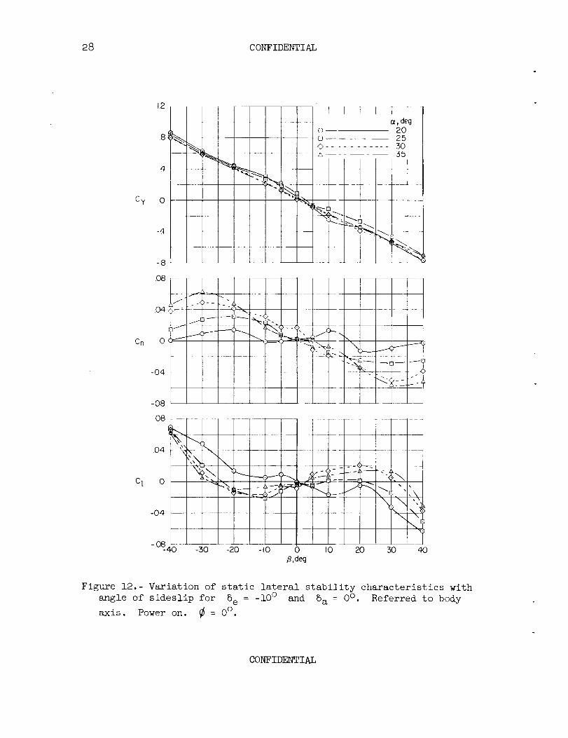
nary force tests were made, and the results are presented in figure 12.
In order to approximate the actual flight condilions in the tunnel, the
tests were made with the elevons trimmed up -10 c' and the thrust adjusted
to give zero d_ag along the wind axis for the zero sideslip condition.
CONFIDENTIAL

CONFIDENTIAL 13
The data from these force tests which covered a range of angle ofattack from 20° to 50° showthat the model is directionally unstableat angles of sideslip up to 20° or 30° throughout this angle-of-attackrange except at _ = 20° where the model is slightly stable. Theeffective dihedral varies from stable at an angle of attack of 20° tounstable at angles between 25° and 45° and to about neutral at 50° .The data indicate that the model might have a tendency to trim in rolland yaw at large angles of sideslip, but this result is not clear fromthis presentation of the data. In order to bring out this characteris-tic more clearly, the data have been recomputed and plotted in figure 13to showthe variation of yawing- and rolling-moment coefficient withangle of bank about the body axis. If the model simply rolls about thebody axis, an angle of sideslip equal to if sin _ is introduced, andthe angle of attack becomesequal tO if cos _. Figure 13 was obtainedby the use of these simple angular relations and interpolation from thedata of figure 12. The data of figure 13 clearly show that the modelwas unstable at small angles of bank and had stable trim points at highangles of bank. A relatively small amount of roll- or yaw-controldeflection would makeboth the yawing- and rolling-moment curves trimto zero momentat the sameangle of bank; therefore, a stable trimmedcondition at about a 45° bank similar to that encountered in the flighttests would be indicated. The model can perform a simple bank such asthis without muchchange in its angle of pitch to compensatefor a lossin lift because of its large side force which supplies the verticalforce required to replace that lost by the wing.
SUMMARYOFRESULTS
The results of a flight investigation of the stability and controlcharacteristics of a jet-powered vertical-attitude VTOLresearch air-plane can be summarizedas follows:
i. In hovering flight the model could be flown smoothly and easilywithout any automatic stabilization devices whenthe gyroscopic effectsof the jet engine were not represented. The jet-reaction controls pro-vided good controllability, and the model could be movedfairly rapidlyfrom one position to another and restored quickly to a steady-flightcondition.
2. Whenthe engine gyroscopic effects were simulated, the modelcould not be controlled in hovering flight without artificial stabiliza-tion because of the strong gyroscopic coupling of the yawing and pitchingmotions. The use of pitch and yaw dampersmadethese motions completelystable and the model could then be controlled very easily.
CONFIDENTIAL

14 CONFIDENTIAL
3. If the gyroscopic effects of the turbojet engine were simulatedat one-half true scale magnitude to represent an airplane with an engineof more advanced (lighter) design, the model could be flown withoutartificial stabilization for short periods o5 time but then went out ofcontrol.
4. In the transition tests, which were performed only with the auto-matic pitch and yaw dampersoperating, it was found that the transitionwas very easy to perform either with or without the gyroscopic effectsof the jet engine simulated, even though the model had a tendency tofly in a rolled and sideslipped attitude between angles of attack ofapproximately 25° and 45°. This sideslippin[ tendency resulted fromthe fact that the model was unstable in yaw and roll in this angle-of-attack range but had a stable trim point at large angles of bank andsideslip.
5. The swiveling nozzle on the main jet provided good yaw and pitchcontrol through the entire speed range covered in the investigation.
Langley Research Center,National Aeronautics and Space Administration,
Langley Field, Va., August 19, 1954.
REFERENCES
i. Schade, Robert 0.: Flight-Test Investigation on the Langley Control-Line Facility of a Model of a Propeller-Driven Tail-Sitter-TypeVertical-Take-0ff Airplane With Delta Wing During Rapid Transitions.NACATN 4070, 1957.
2. Kirby, Robert H.: Flight Investigation of the Stability and ControlCharacteristics of a Vertically Rising Airplane Research Model WithSwept or UnsweptWings and X- or +-Tails. NACATN 3812, 1956.
3. Lovell, Powell M., Jr., and Parlett, Lysle P.: Effects of Wing Posi-tion and Vertical-Tail Configuration on 3tability and ControlCharacteristics of a Jet-Powered Delta-Wing Vertically Rising Air-plane Model. NACATN 3899, 1957.
CONFIDENTIAL

CONFIDENTIAL 15
TABLEI
GEOMETRICCHARACTERISTICSOFMODEL
Wing (modified triangular plan form):Sweepback,deg ....................... 60Airfoil section .................... NACA65A008Aspect ratio ........................ 1.97Area, sq in ........................ 1,094.4Span, in ........................... 46.4Meanaerodynamic chord, in ................ 29.1Momentarm of roll nozzles, in ................ 24.375Incidence, deg ......................... 4Dihedral, deg ........................ 0
Overall length of model, in ................. 56.25
Vertical tail (modified triangular plan form):Sweepback,deg ....................... 45Airfoil section .................... NACA65A012Aspect ratio ........................ 1.76Area, sq in ......................... 270Span, in .......................... 22
Outboard fin:Airfoil section .................... NACA65AOllArea, each, sq in ..................... 23.4Area, total, sq in ...................... 46_8Aspect ratio ....................... 3-57Span, in ........................ 9.14Root chord, in ........................ 7.02Tip chord, in ........................ 3.07
CONFIDENTIAL

16 CONFIDENTIAL
TABLEII
MASSCHARACTERISTICSOFMODEL
Weight:Indoor tests with compressed-air power ........... 31.73Outdoor tests with hydrogen-peroxide rocket power ..... 39.3
Center-of-gravity location:Distance from leading edge of M.A.C., percent M.A.C. 3o.4
Inertia of model:
Indoor tests:
IX, slug-ft 2 ....................... 0.603
Iy, slug-ft 2 ........................ 1.473
IZ, slug-ft 2 ....................... 1. SlO
Outdoor tests:
IX, slug-ft 2 ........................
Iy, slug-ft 2 ........................
IZ, slug-ft 2 .......................
0.603
1.784
i. 821
CONFIDENTIAL

3C CONFIDENTIAL 17
Of_!
!
/
/
!
©
©
©
o
-p
,o
©,.p
I
(D
I
©
bD

18 CONFIDENTIAL
O!
_c
!kJl
O_
_h
!
oE
_Z
o
©h
!
!
c_
©
h0
CONFIDENTIAL

CONFIDENTIAL 19
\ _iIII_;,IV-!\ !J ; /1/_', I/
6'
56.25 _, ¢.5,',, --'--\ b IQ' ' ,I,
60_ 82
Nose
_--< 46.4 L48.8 +
Figure 3.- Three-view sketch of the model used in the tests. All dimen-sions are in inches.
CONFIDENTIAL

20 CONFIDENTIAL
T =
+_
O_
(D
o
_J
Xo
ODO
®
40
O
>
40ZO
+_
Zo_i
I
3(1)
CONFIDENTIAL

CONFIDENTIAL 21
_?ffhcw-?ohi
o
,o
(D
+_
h
gCk
(I)
.r.-i
o
bOo
,..c:
4_
o
>
o
co
i
G)
CONFIDENTIAL

22 CONFIDENTIAL
_1o /\\ ,
4_
J
o
r_
!
o.I
r_
CONFIDENTIAL

CONFIDENTIAL 23
©
o(Di
@
bD
+_
4o
r-4
oq-4
4-_
+._m©
E-4
!
or-I
CONFIDENTIAL

24 CONFIDENTIAL
4o-r-t
e_
©
"H,--t
!
H0
4o
0
£-t
I
_d
._-I
CONFIDENTIAL
4C CONFIDENTIAL 2_
co
i.
cJ!
O,-4
o4
(7",I
<J-HX0
hOo
b9
• or'l
,-4"0
0
-In
la/
-r-t
I
&
.H
CONFIDENTIAL

26 CONFIDENTIAL
D_
_0 _o -•,- a. _0 -z
z_ _ ,
' z o
t_
0_000
Z
b,.
4,--
2
oif)
_o o _.
G_>
OJZ
to
c--
co
,,I,,--
c-O
LI.
0
r,,
.,,I,--
.._.>
o0 >
0 r- 0
0
bO0
0
4._
r-I
!
,'-I
COI_I_

CONFIDENTIAL 27
0GO
I!
_LO
/
%
0
Lo'O
0 LO O_
o o
c--
00
0CO
8
0
o
0
0
0
_D
0
,Ul_D(D
.,-4
\ g
©
.r-.I
%
U
0
t_O
I
,-4
.r--t
CONFIDENTIAL
28 CONFIDENTIAL
Cy
CD
1,2
8{
4
0
-4
-8
I I U F T- I
cI,dego 20
25/_ ........... 30A--- 35
I I
O8
04
c l o
-04
- 08_4O
..............I
I
X
-30 -20 - I0 0 I0 20 30 40,B,deg
Figure 12.- Variation of static lateral stability characteristics with
angle of sideslip for 8e = -i0 ° and 8a = 0°" Referred to body
axis. Power on. _ = 0°.
CONFIDENTIAL

5C CONFIDENTIAL 29
cou'h-!
oJ!o,-4
Cy
Cn
C1
1.2
4
0
-4
-.8
-12
08
.O4
0
-O4
/ ,--...
-.O8
08
k.04 _ ,
__ (z,deg,r_ 40' _ 45
e .......... 50
,k.
- -I
"q:%_' __i_ _-_ _ c_,'__--50 -20 -I0 0 I0 20 :50 40
,8,deg
Figure 12.- Concluded.
CONFIDENTIAL

5o CONFIDENTIAL
Ca
,O8
04
0
-04
-O8
f-
/
tYf
Y \
_-_ 40.......... 50
_4 / /\
.O8
.O4
C] 0
-.04
\
• \
\
/
-.O8
-60 -40 -20 0 20 40 60
+, deg
Figure 13.- Variation of C_ and Cn with _ about the body axis for
several angles of attack. 5e = -lOO, 8a = 0°.
CONFIDENTIAL .As^-L_.gi_yrl.ld,w.