nasa technical nasa x-71669 technical nasa tm x ... solar electric propulsion spacecraft is largely...
TRANSCRIPT
NASA TECHNICAL NASA TM X-71669MEMORANDUM
--
(NASA-TM-X-71669) SPACECRAFT ATTITUDE N75-17406 1
CONTROL FOR A SOLAR ELECTRIC GEOSYNCHRONOUS
TRANSFER MISSION (NASA) 14 p HC $3.25CSCL 22B Unclas
G3/18 11760
SPACECRAFT ATTITUDE-CONTROL FOR A SOLAR
ELECTRIC GEOSYNCHRONOUS TRANSFER MISSION
by Bruce E. LeRoy and John D. Regetz
Lewis Research Center
Cleveland, Ohio 44135
TECHNICAL PAPER to be presented atEleventh Electric Propulsion Conference sponsored
by American Institute of Aeronautics and Astronautics
New Orleans, Louisiana, March 19-21,'1975
https://ntrs.nasa.gov/search.jsp?R=19750009334 2018-07-10T14:03:42+00:00Z
SPACECRAFT ATTITUDE CONTROL FOR A SOLAR ELECTRIC GEOSYNCHRONOUS TRANSFER MISSION
Bruce E. LeRoy and John D. RegetzLewis Reserach Center
National Aeronautics and Space AdministrationCleveland, Ohio
Abstract recently at the Lewis Research Center in supportof the proposed SERT C spacecraft.(l) For this
A study of the Attitude Control System (ACS) reason, the sample mission and spacecraft describedis made for a solar electric propulsion geosynchro- herein have similar, although not identical, char-nous transfer mission. The basic mission considered acteristics to SERT C. These are described moreis spacecraft injection into a low altitude, in- fully in the Mission Description and Spacecraftclined orbit followed by low thrust orbit changing Description Sections. A section is also includedto achieve geosynchronous orbit. Because of the which describes the range of environmental condi-extended thrusting time, the mission performance is tions encountered by the spacecraft during orbita strong function of the attitude control system. transfer.Two attitude control system design options for anexample mission evolve from consideration of the Using the sample mission and spacecraft, thisspacecraft configuration, the environmental dis- paper does the following: First, it identifies theturbances, and the probable ACS modes of operation. basic modes of operation required of the ACS; Sec-The impact of these design options on other space- ond, it examines qualitatively the tradeoffs be-
, craft subsystems is discussed. The paper presents tween various ACS components and design options;S a discussion of the factors which must be considered and third, it identifies the impact of variouswt in determining the ACS actuation and sensing sub- ACS design options on other spacecraft systems and
systems. The effects of the actuation and sensing on mission performance. It is not the purpose ofsubsystems on the mission performance are also con- this paper to develop detailed requirements on thesidered. ACS, but to describe qualitatively the unique prob-
lems engendered by the use of low thrust SEP forIntroduction orbit transfer. It is felt that the information
and discussions presented herein will provide theRecently, much interest has been evinced in system engineers with a basis from which they can
the use of Solar Electric Propulsion (SEP) to trans- more readily evolve detailed spacecraft subsystemfer a payload from a low-energy geocentric orbit to designs.one of higher energy, generally geosynchronous.The high specific impulse of electric thrusters Mission Descriptionpermits transfer of a significantly larger payloadthan does chemical propulsion, for a given launch General Mission. The basic solar electricvehicle. Similarly, a given final payload can be geosynchronous transfer mission can be summarizeddelivered by a smaller, less expensive launch ve- as simply the application of electric propulsionhicle using electric propulsion. Hand-in-hand to transfer a spacecraft from a low altitude orbitwith the high specific impulse, however, goes low toa geosynchronous orbit. While the final orbitthrust. Thus, instead of a matter of minutes and is well specified; the initial orbit depends onhours, the transfer times using SEP become tens many factors. Spacecraft weight determines theand even hundreds of days. In terms of percentage initial orbit semimajor axis, and the launch ve-of overall mission time, therefore, the orbit trans- hicle determines the initial orbit eccentricity.fer phase becomes a much more significant part of Generally we may expect a launch from ETR, and thusthe mission than is true for chemical transfer. an initial orbit inclination between 250 and 30.The geosynchronous transfer mission presents anextremely wide diversity in spacecraft environment For any given initial and final orbits, thecharacteristics and operational requirements. transfer may be optimized to minimize the transfer
time subject to the spacecraft acceleration capa-During orbit transfer, the spacecraft ACS is bility. The result of the optimizing process is
required to orient the SEP thrust vector so as to a thrust vector orientation history for the mission.accomplish the desired orbit changes, while at the This orientation history then serves as the re-same time keeping solar arrays oriented toward the quired guidance reference to which the ACS controlssun and permitting unbroken communication ability the thrust vector. Generally, a component ofwith the earth. It must do this for an extended acceleration is required in the direction of orbitperiod of time, in the face of a severely changing velocity to increase the semimajor axis. Anspacecraft environment. Because of the extended out-of-plane acceleration component is requiredthrusting time, mission performance is a much to decrease the inclination. During any one orbitstronger function of ACS design and performance this component is a maximum in one sense at the as-than with chemical transfer. Similarly, the ACS cending node and maximum in the opposite sense atdesign impacts other spacecraft systems, notably the descending node, changes in eccentricity arethe thermal control, communications, and power then controlled by the radial component of accel-systems. Because of these factors, it is impor- eration. Although radial component phasing istant to consider the feasibility and desireability variable during the mission, both radially inwardof various attitude control system concepts early and outward components are required during anyin the mission planning effort. one orbit.
This paper presents a discussion of the basic Example Mission. The example mission con-factors which must be considered in the design of sidered is similar to that in Ref. 1. The initialan attitude control system for a SEP orbit transfer orbit is circular with an altitude of about 0.5mission. The basis of the discussion is work done earth radius. The initial inclination is 28.50.
For this initial orbit, the optimum thrust vector- from parallel with the x axis through the center ofing requires an approximately sinusoidal out-of- mass (located about 1.8 m from the - x face) isplane acceleration. The radial acceleration is about 130. If an in-line configuration is chosen,ignored since it is small. The assumptions leading the required gimbal motion for out-board thrustersto this optimum thrust vectoring for this mission is about 270.are that the maximum array power is continuouslyavailable, there is no shadowing, and the array Power is provided by the two solar arrayspower output gradually degrades due to high energy mounted through the + y and - y faces of the space-particle flux. As in the reference the magnitude craft. The arrays are mounted as near the centerof the out-of-plane acceleration increases during of mass as possible to minimize solar pressure dis-the mission, turbances. Each array is 3.05 m by 16.75 m and
provides about 5.5 kW of power. The solar arraysSpacecraft Description are the dominating contributors to the spacecraft
moments of inertia. The inertias are about 22 175,General. The physical configuration of a 875 and 22 850 kg m
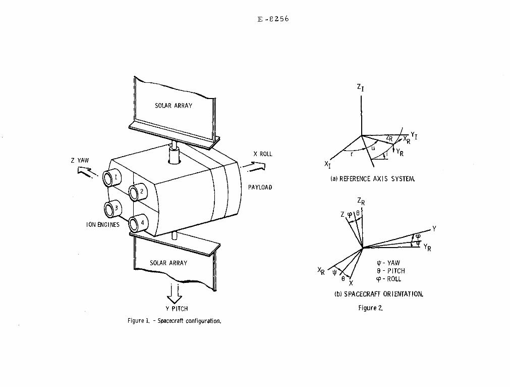
2 in the x, y and z axes for a
solar electric propulsion spacecraft is largely total spacecraft mass of 1000 kg. The mass of thedictated by the thermal and power subsystems. deployed arrays is 200 kg.Generally, the configuration is that of a rigidcenter body and two flexible solar arrays attached The nominal acceleration is along the space--to opposite center body faces. The solar arrays craft + x axis for all four thrusters or for diag-have a single degree of rotational freedom with nally opposite (symmetric) thrusters operating. Torespect to the center body, and power from the produce the nut-of-plane accelerations required forarrays is transmitted to the center body through our example mission, the entire spacecraft is ro-slipring assemblies. For geosynchronous orbit tated as opposed to gimballing the thrusters. Tooperations (earth pointing) the axis of array define the spacecraft rotational motions we firstrotation would be north-south, and the north and establish a reference axis system shown in Fig.south faces of the center body would be used for 2(a). The XI, YI, and ZI system is the earththermal control. The 30 cm thrusters used for centered inertial system with XI along the vernalprime propulsion must be mounted to the center body equinox. The XR, YR, and ZR reference system isso that thruster plume impingement on the solar a satellite centered system with ZR toward eartharrays is avoided. center, YR perpendicular to the orbit plane, and
XR perpendicular to the radius vector and nomi-There are several configurations of thruster nally along the orbit velocity vector. When the
mountings which may be considered. The basic dif- yaw, pitch and roll angles are all zero the space-ference in configurations is whether each thruster craft axes (fig. 1) coincide with the referenceis mounted and gimballed separately or whether the axes. Any spacecraft orientation may be achievedthrusters are grouped and mounted on a gimballed as shown in Fig. 2(b) by first yawing the space-platform. From the attitude control point of view craft, then pitching the spacecraft, then rollingthe platform mounting is less attractive for the the spacecraft. For symmetric operating thrusters,following reasons: (1) if the prime propulsion the out-of-plane acceleration is achieved by sim-system is to be used for attitude control, at least ply yawing the spacecraft in approximately sinus-two platforms are required for production of con- oidal fashion over one orbit. If non-symmetrictrol torques about all three spacecraft axis, and or an odd number of thrusters is operating, the(2) for any two thruster fixed to a platform the spacecraft yaw and pitch angles must be biased tothrust vectors may be slightly skewed thus creating accelerate the spacecraft in the proper directiona disturbance torque on the spacecraft which can- with respect to the reference axes; The maximumnot be eliminated by platform gimballing. If each acceleration is achieved when all thrust vectorsof the thrusters is individually gimballed, then are parallel and the net thrust is through thethe thrusters may be arranged in a line ("1 by" center of mass.configuration), or in pairs ("2 by" configuration),etc. Either the line or pair configuration is Disturbances Torquesfavored since thermal control of the thrusters andpower processors for these configurations is more The disturbance torques acting on the space-easily accomplished than for other configurations. craft during orbit transfer may be separated intoIn addition, the line or pair configuration lends two categories. The first category includes theitself to modular design. Conceivably each module environmental torques; the second category includescontains thruster, gimbals, power processor, ther- disturbances produced by the spacecraft subsystems.mal control and common propellant plumbing.(2)The modules would form the basic structure of the Environmental. The major environmental dis-spacecraft. turbances for the transfer mission are gravity-
gradient torque, magnetic torques and solar pres-Example Sapcecraft. ,),he example spacecraft sure torques. Table I shows the maximum values of
configuration is shown in Fi Wl and is basically these disturbances for low altitude and synchro-similar to that used in other studies (1,3,4,5,6). nous altitude. The low altitude gravity-gradientThe center body dimensions are 1.22- by 1.22- by torque is the maximum environmental torque and will3.25 m, and it houses most spacecraft subsystems. be evident primarily about the roll axis for ourA payload section is provided on the spacecraft example mission and spacecraft. The magnetic+ x axis, and the four 30 cm prime propulsion torque was estimated for a net spacecraft dipolethrusters are mounted on the spacecraft - x face. of 10 A m
2. The estimated disturbance due to solar
Each thruster is two-axis gimballed, and the pressure is based on a 0.1 m separation of the"2 by" configuration was chosen to minimize the spacecraft center of pressure and center of mass.required gimbal angles. For the "2 by" configura- Aerodynamic drag was found to be negligable attion total gimbal motion to point each thruster the initial altitude. The high altitude values of
2ORIGINAL PAG]E ]I
IOF POOR QUALI"
gravity-gradient and magnetic torques are two initial conditions.orders of magnitude less than the initial values.T~e solar pressure disturbance is essentially in- Checkout. A probable mode of operation is adependant of altitude. checkout period during which the spacecraft sub-
systems, excluding thrusters, are exercised. ThisSpacecraft Induced Torques. Disturbances mode may last from a few hours to a few days and
induced by the spacecraft subsystems are highly allows establishment of the spacecraft status priorcomplex and deserving of detailed examination that to initiation of prime propulsion. At the simplestis beyond the scope of this paper. The effects level, the ACS requirements during this mode areof solar array flexibility have been studied for to maintain yaw, pitch, and roll angles approxi-linearized-cases, and the reader is referred to mately near zero and assure adequate housekeepingthe Refs. 3,4,5,7,8,8, and 10. The essential prob- power from the solar arrays. Some maneuvers maylem concerning flexibility is that the solar array be required to checkout communication antennaflexible motions induce small motions of the patterns and/or the thermal control system in thecenter body. These motions, while not unstable in presence of high earth albedo. A choice in sen-themselves, may be sensed and magnified by the sors is not implied by this mode; however, we noteACS, resulting in a deterioration in performance that control actuation is not necessarily limitedor instability. Another potential source of dis- to an auxilary low impulse propulsion system, andturbance is the mercury propellant management wheels may be considered.system. As the propellent is used we can expecta very slow shift in spacecraft center of mass. Thruster Calibration. Whether or not theIn addition, higher frequency center of mass 30 cm thrusters are used for attitude controlshifts and inertial torques can be present due to actuation, the thruster start-up mode is envisionedpropellent slosh. Thruster gimballing may also as a calibration of the thruster and gimbal sys-produce center of mass shifts and inertial torque. tems. This is necessary due to the potentiallyThe thruster motion inertial torque can lead to large disturbance torques from thruster misalign-the familiar "tail wags dog" effect. The critical ment and the inability to measure precisely thefrequency (that frequency at which the inertial location of the deployed spacecraft center of mass.torque equals the torque produced by thrust mis- Before operation, each thruster would be alignedalignment from the center of mass) has been esti- through the prelaunch calculated location of themated for our example spacecraft at 0.155 rad/sec center of mass to minimize initial disturbances.for a single operating thruster. Any static Once in operation, each thrust vector would bethruster misalignment from the center of mass will aligned through the current center of mass. Thisalso produce a disturbance torque. A single thrust process would provide information on thruster-vector misaligned by 0.10 can produce a disturbance thrust vector misalignment, center mass location,torque of 4.3x10⁻⁴ Nm in the yaw-pitch plane. gimbal system backlash, etc. before proceeding toThis is equivalent to an error of about 0.3 cm in vector the spacecraft acceleration. The ACS wouldthe knowledge of center of mass location. A dis- be used to aid the calibration, since position,turbance torque about the roll axis of about rate and control torque information can be used1.4x10-4 Nm is possible for a differential mis- to determine thrust vector misalignment. Obviouslyalignment of 0.10 for two thrust vectors. Torques if a short time limit is imposed on the calibration,produced by thrust vector misalignments can be then sensor accuracy affects the ability to alignthe dominating disturbance at high altitudes, the thrusters. For our example spacecraft and the
disturbances quoted for a 0.10 thruster misalign-Modes of Operation ment, the pitch motion is 20 in slightly over 6
minutes. The equivalent torque in yaw produces aThe purpose of this section is to identify 0.10 motion in slightly over 7 minutes. Thus if
the probable modes of operation for our example position information is used in the calibration,mission. Table II presents a summary of this the yaw accuracy should be about 0.10. Since thesection. 30 cm thrusters would not be used for control ac-
tuation during this mode, the auxilary propulsionAquisition. Since we have not specified the system or momentum storage would be used.
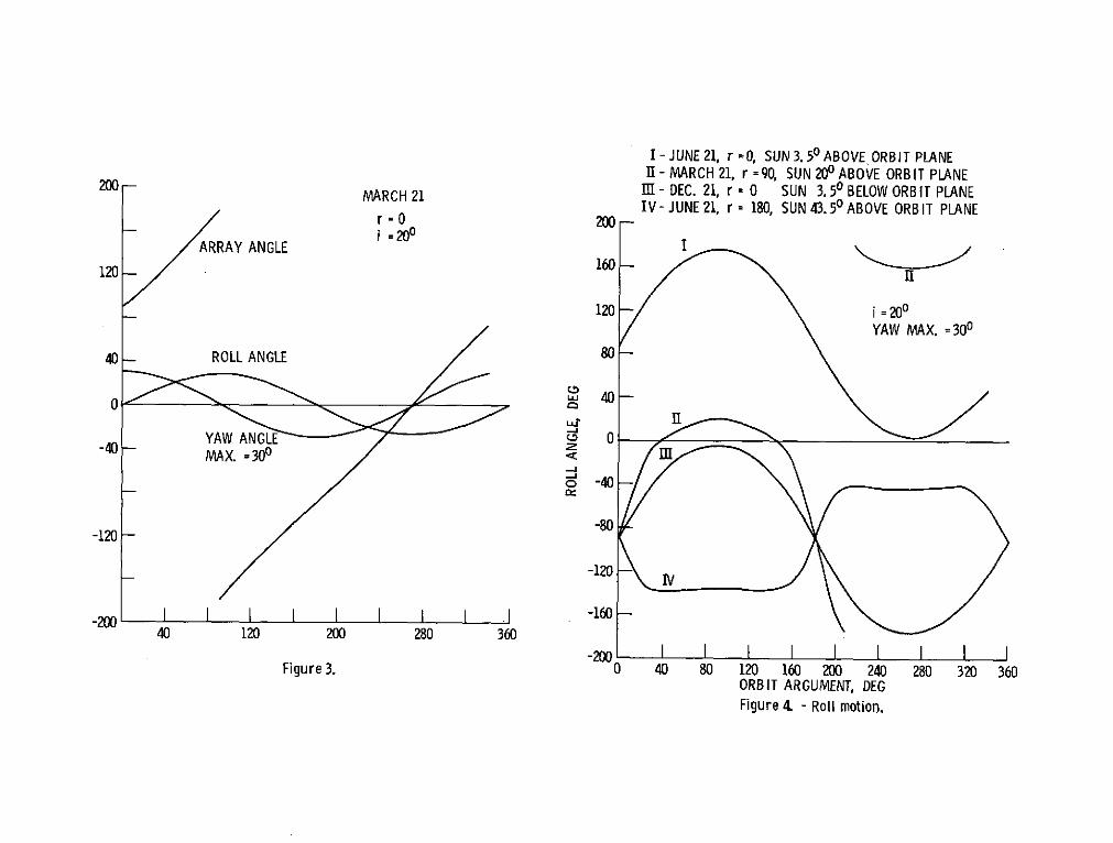
booster, the rate and orientation initial condi-tions from which the spacecraft must acquire are Thrust Steering. The thrust steering mode isconsidered random. The requirement on the ACS the major operating mode during orbit transfer.during this mode of operation can then be listed In this mode the thrust vector is pointed accord-as: (1) nulling spacecraft rates, (2) acquiring ing to the guidance equations to raise altitude,the sun, (3) insuring orderly deployment of the and eliminate the eccentricity and inclination.solar arrays, and (4) acquiring the second posi- For maximum acceleration the operating thrusterstion reference (earth or star). Functions 1, 2, are gimballed so that the thrust vectors are par-and 3 must be accomplished within a fixed time allel and the net thrust is through the center oflimit, since batteries will probably be used for mass. For our example mission and spacecraft, thepower until the arrays are deployed. For this optimum guidance may be approximated by simplymode the ACS requires rate sensing and sun sensing. yawing the spacecraft in sinusoidal fashion.Specific requirements on the rate sensing compo- This, of course, assumes that all four or symmetricnents cannot be specified unti1a booster is pairs of thrusters are operating. The magnitude ofchosen. Given the random initial orientation, the pitch and yaw biases when operating three4r steradian sun sensor coverage will probably thrusters is 3.20 for our example spacecraft.be required. The method of control actuation mostsuitable for this mode is a low impulse auxilary If continuous maximum power is required, thenpropulsion system. Some argument for using wheels the ACS must roll the spacecraft so that the pitchfor actuation can be made; however, using wheels axis is perpendicular to the spacecraft-sun line.alone severely limits the acceptable acquisition Figure 3 shows an example of the yaw, roll and
ORIGINAL PAGE ]B 3
OF POOR QUALIT j
~array rotational motions required as a function of figs. 3 and 4, one can safely argue that the sensingsatellite argument in the orbit (see fig. 1). The system is more complex and the control energy ex-orbit parameters for Fig. 3 are an ascending mode pended is greater than if roll motion is limited toat 00 and an inclination of 200. The choice of small angles or even zero. Thus, in subsequent dis-date locates the sun at the vernal equinox. Fig- cussions on the ACS sensing and actuation subsystemsure 4 expands the analysis of the required roll we will consider both unlimited and limited rollimotion for maximum power to include additional motion as viable design options for the thrustsun-orbit relative locations. For all relative steering mode.positions of the sun and orbit, the roll motionrequired for maximum power is cyclic and contin- Obviously, the guidance and navigation analysisuous. For large roll motion, gimballed or multi- is more complex if the roll motion is restricted.ple sensing is required, and conceivably the gim- In addition to shadowing and solar degradation, theballed prime propulsion thrusters could be used effects of throttling the thrusters to match thefor control actuation. The sensing, actuation large power variations over one orbit must now beand the necessity for maximum power for this mode included in the analysis. The effects of bothof operation are subjects for tradeoff studies design options on other spacecraft subsystems isappearing later in this paper. discussed below for out example mission.
Orbit Trim. Another distinct mode of oper- Thermal. If roll motion is unrestricted duringation may be required when the spacecraft is near the thrust steering mode, then the +Y and -Y facessynchronous orbit. During this mode, final ad- used for thermal control will never see direct sun-justments to orbit parameters are made and some light. However, the control faces will see largecoasting may be required to achieve the proper earth albedo effects at the lower altitudes. Iflongitude in geosynchronous orbit. A reduction in roll motion is restricted to small angles, then theeccentricity without changing the orbit semi- problem of earth albedo is eliminated, but some di-major axis is accomplished by accelerating the rect sunlight will be seen by the control faces.spacecraft in the - XR direction at orbit perigee Note that some direct sunlight will be seen by the"and accelerating in the +XR direction at orbit control faces during earth pointy geosynchronous or-apogee. A reduction in orbit inclination is bit operations, and some direct sunlight may be seenaccomplished by accelerating the spacecraft in during thrust calibration and orbit train modes.the +YR direction at the descending mode. No Thus, the thermal control faces will probably be de-new implications on the ACS configuration are signed to accommodate some direct sunlight, and itfound by considering this mode. remains to be determined if a mass or performance
penalty must be assessed against the thermal systemEclipse. During orbit transfer and geo- for restricted roll motion during the thrust steer-
synchronous orbit the spacecraft will be eclipsed ing mode.by the earth. Obviously, during this mode thesun is not available for position reference, and Communications. If roll motion is unre-the prime propulsion thrusters cannot be used stricted, the communications antenna system mustfor control actuation. Just prior to intering the have acceptable gain pattern nulls in the pitch-yaweclipse the 30 cm thrusters would be turned off. spacecraft plane. If roll motion is restricted,The ACS, then, is required to maintain guidance directional, higher gain antennas can be used sincepointing when the thrust is terminated and when the spacecraft yaw axis is earth oriented.thrust is initiated after eclipse. Unless allthrusters are turned off and on simultaneously, Power and Thruster Systems. If roll motion isor unless the thrust is pointed through the center unrestricted, the thrusters would be throttledof mass, the spacecraft will be subjected to slowly to match the degradation in array power duerather large short term disturbances. For our to high energy particle flux. Under this condi-example spacecraft, the distrubance torque pro- tion, the power system could probably monitor orduced by a single thruster, whose thrust vector calculate the array peak power easily. When rollis parallel to the X axis, is 0.058 N.m. in the motion is restricted, rather fast variations occurY-Z spacecraft plane. in available array power. Care must be taken to
avoid electrical collapsing of the array by demand-Momentum Dumping. If momentum storage de- ing too much power for thrusters. The power system
vices are used for control during any of the above must then be able to calculate, measure, or predictmodes, then periodic momentum dumping is required. power during any one orbit, and the thrusters mustThe ACS must use the auxilary propulsion or prime be throttled accordingly. For the mission analyzedpropulsion systems for this purpose. in Ref. 1, the power variation over the orbit which
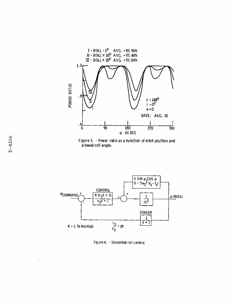
required the widest range of thruster throttling isDesign Option Impact shown in Fig. 5, curve I. We can expect similar
variations in our example mission. The power ratioAs noted in the previous sections the geosyn- is just the cosine of the array misalignment from
chronous transfer mission can be optimized to min- the sun, and it varies from about .71 to 1.0 withimize the transfer time. Thieoptimizing process four distinct throttling areas over this orbit.presently used generally assume that the solar ar- The average power is about 90%, and thus the aver-rays are always pointed directly at the sun so that age acceleration is 90% of the maximum available.the maximum power is available. If the solar ar- Causes II and III show that some improvement inrays are misaligned from the sun the thrusters must throttling range and average power can be achievedbe throttled thus reducing the spacecraft accelera- if small roll motions are allowed. Curve II is fortion and requiring more time to perform the orbit roll angles less than 100 and shows the throttlingtransfer. Yet, orienting the spacecraft to achieve range to be about .77 to 1.0 with a definite "flat-maximum power produces penalties in terms of net tening"of two of the throttling areas. Curve IIIpayload mass and ACS complexity. Given the larg- is for roll angles less than 200 and shows theer roll angles for our example mission shown in throttling range to be about .83 to 1.0 with a com-
ORIGINAL PAGE . 4OF POOR QUALTm
plete elimination of two throttling areas. half an orbit, the total momentum required per orbitis 140 Nm sec. Assuming a system specific impulse
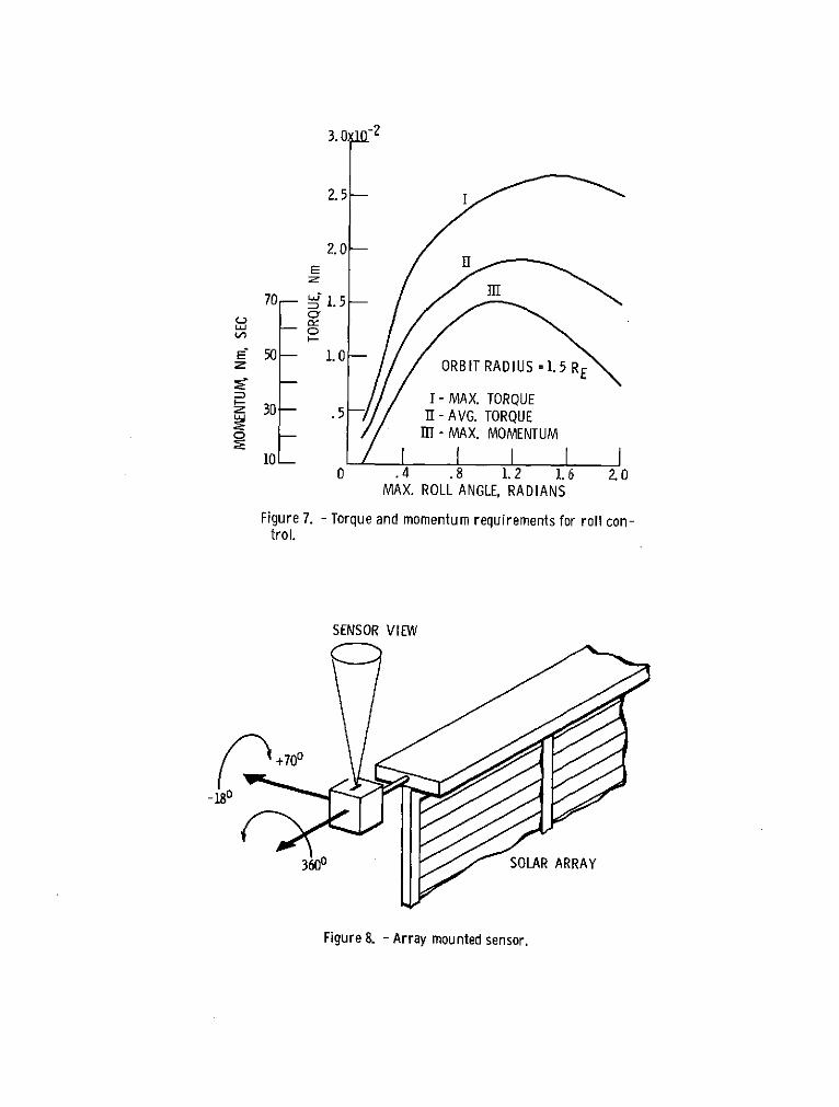
Summary. In summary, we may say that for our of 200 sec, the propellent used for our exampleexample mission restricting roll motion simplifies spacecraft is .114 kg per orbit.the communications and attitude control systems,while unlimited roll motion simplifies mission anal- Limited Roll Motion. As can be seen from fig.ysis and the power system. It has yet to be de- 7 the control requirements are drastically reduced
termined how the thermal system is affected. as the commanded roll angle magnitude decreases. Ifwe assume that the roll motion is limited to about
Actuation Tradeoffs .3 radians (% 180), then the maximum torque is about1.2x10
-2 Nm, the maximum average torque is about
The purpose of this section is to examine in a 9.0x10- 3
Nm and the maximum momentum is 30 Nm sec.qualitative manner the tradeoffs which may be made In the same manner as above, we find that the gimbal-in the selection of the prime actuators for our ex- ling required to produce the maximum torque is 8.50ample mission and in particular the thrust steering for a single small thruster or two 30 cm thrusters
modes. The discussion is limited to the following and 4.250 for two small thrusters or four 30 cmitems. (1) gimbaled 30 cm thrusters, (2) hot gas thrusters. The 30 cm thruster gimballing to produceauxiliary propulsion system, (3) momentum wheels, the average torque is about 6.50 for two thrusters
and (4) small ion thrusters (8 cm, 5 cm). Items 1, and 3.250 for four thrusters. The attendant loss in2, and 3 have already been mentioned in the discus- average net acceleration is about 0.6% for two
sions on probable modes of operation. The small ion thrusters and about 0.2% for four thrusters. Con-thrusters are considered only because they may be sidering the momentum, the required wheel mass is
required for station keeping in geosynchronous orbit. about 20 kg and the propellant usage is about .05 kgper orbit. Table III summarizes the above.
During the thrust steering mode, the two basicACS design options are either unlimited or limited Tradeoffs. If the tradeoff criterion is the
roll motion. To assess the required control capa- usable payload delivered to synchronous orbit in a
bility, a simple, single-axis rigid body analysis is fixed time, then based on the above discussions a
made for a 1.5 RE orbit radius. We assume that the "worst case" tradeoff can be made for the unlimited
commanded roll angle is a sinusoid at orbit frequen- roll ACS design option. As a basis, consider the
cy, and that gravity-gradient is the only external optimum mission with full power, maximum accelera-
disturbance. A block diagram of the system is shown tion and no required control energy. Thus the mass
in fig. 6. The controller is a simple lead-lag sys- used for control will be considered a penalty on the
tem with an overall gain of 1.76 Nm/rad. This gain payload delivered in optimum fashion. The use of
was chosen from a linear analysis of the closed-loop the 30 cm thrusters for control reduces the maximum
system for a 2% error in step response. available thrust by 1% to 3%. Thus to deliver thepayload in the same fixed time required a comparable
The results of this study are summarized in reduction in total spacecraft mass (to maintain max-
fig. 7. The figure shows the maximum torque, aver- imum acceleration). For our example spacecraft with
age torque, and maximum momentum storage required a base mass of 1000 kg, the corresponding penalty
for control as a function of roll angle. would be 10 to 30 kg. If wheels, small ion thrust-ers on the auxiliary propulsion system were used for
Unlimited Roll Motion. For unlimited roll mo- control, then there would be no reduction in total
tion the actuators must be capable of producing the spacecraft mass. However, a net reduction in usable
maximum required torque of .027 Nm. This should be payload (payload penalty) would occur due to the ac-
well within the range of momentum wheels and the tuation mass. The penalty for the use of wheels is
auxiliary propulsion system. Small ion thrusters about 47 kg. The penalty for using the auxiliarymounted on the ends of the arrays could also produce propulsion system can be estimated by multiplying
the maximum torque if they are gimballed. A gimbal the propellant usage per orbit by the number of or-
angle of 200 is required for one thruster or about bits during the thrust steering mode. Our "worst
100 using two thrusters. Using two 30 cm thrusters case" estimate for 400 orbits is 46 kg. Because the
the differential gimballing required is about 200 small ion thrusters were presumed available for syn-and for four thrusters about 100. Thus all con- chronous orbit operations, the penalty for the use
sidered actuators can produce the maximum required of these as actuators is quite small. The penalty
torque. is the sum of the extra propellant and additionalarray required for operation of the thrusters dur-
The average torque becomes important when con- ing the thrust steering mode. The extra propellant
sidering the use of the gimballed 30 cm thrusters. mass is 6.5 kg for 200 days operation, and the extra
To produce the maximum average of 1.9xlO- 2
Nm, re- array mass is 6.5 kg for 300 watts power for two
quires 13.50 differential gimballing of two thrust- small thrusters. Thus the total payload penalty
ers or 6.750 gimballing of all four thrusters. Thus could be about 13 kg. If the small ion thrusters
for two thrusters there is a decrease in the net are not already part of the spacecraft, then this
acceleration, due to gimballing of 3%, but for four penalty increases to 30 kg with the inclusion of
thrusters the decrease is about 1%. 17 kg for hardware (thrusters, tankage, gimbals,etc).
The maximum momentum storage requirement is im-
portant if wheels are considered for control. To The payload penalties given above show that
store 70 Nm sec could conceivably require a wheel the 30 cm thrusters or the small ion thrusters are
mass of 47 Kg. The estimate is based on extropola- the best solutions for unlimited roll control. How-
tion of current hardware weights or the use of mul- ever, we must note that the 30 cm thruster and aux-
tiple wheels. We may also use the maximum momentum iliary propulsion system penalties are "worst case",to estimate the auxiliary propulsion system propel- since they were estimated by using a low altitude
ent usage. Since the momentum build up occurs over
5
orbit to determine control requirements. The true ited, a natural mounting location for an earth sen-penalty for using these systems would be less, since sor is on the +Z face of the spacecraft centerbody.the gravity gradient disturbance decreases as the In this location, the sensor provides roll andcube of the orbit radius (1/R
3). Thus, for a pitch information, and it is not affected by the
true comparison the integrated control requirements spacecraft yaw motions required during the thrustmust be found over the duration of the thrust steering mode. If the linear range of the sensor issteering mode. small, or a function of the apparent earth size,
some small angle gimballing of the sensor may be re-A complete comparison would also consider the quired to permit spacecraft roll angles up to 200.
complexity of the actuation system. For example, The chief disadvantage in using the earth sensor inone would attempt to weigh the complexity of gim- conjunction with sun sensors is that during equinoxballing small ion thrusters mounted at the ends of periods the earth vector and sun vector are nearlyrotating flexible arrays as compared to the paralled twice each orbit. Attitude reference in-straightforward application of wheels of the auxil- formation during these periods is not complete, andiary propulsion system. In addition, one would therefore additional reference must be provided.consider the limited and unlimited roll control This additional reference can be provided for themethods. For the restricted roll design the pay- least mass by using a single axis inertial refer-load penalty due to actuation drops significantly, ence gyro. The mass of the total earth sensing sys-The "worst case" penalty for use of the 30 cm tem is estimated at about 20 kg. This total assumesthrusters is 2-6 kg. The estimated wheel mass is that the sensor mass is about 14 kg, that the iner-20 kg, and the worst case auxiliary propulsion sys- tial component is about 3kg, and that the sensortem propellant is 20 kg. The penalty for using the gimballing requires 3 kg. The sensor mass is prob-small ion thrusters does not change, since control ably the largest of current hardware. Array masstorque are generated by gimballing the continuously for this sensor is negligible since the maximum ex-operating thrusters. Thus, the propellent, array pected power usage is 20 watts.and hardware mass penalties for using the small ionthrusters are the same for limited and unlimited Unlike the earth sensor, the star sensor pre-roll control. sents mounting problems to the system designer,
Mounting locations on the +Y or -Y face of theThe prime payload penalty for the restricted spacecraft are occulted by the array as the array
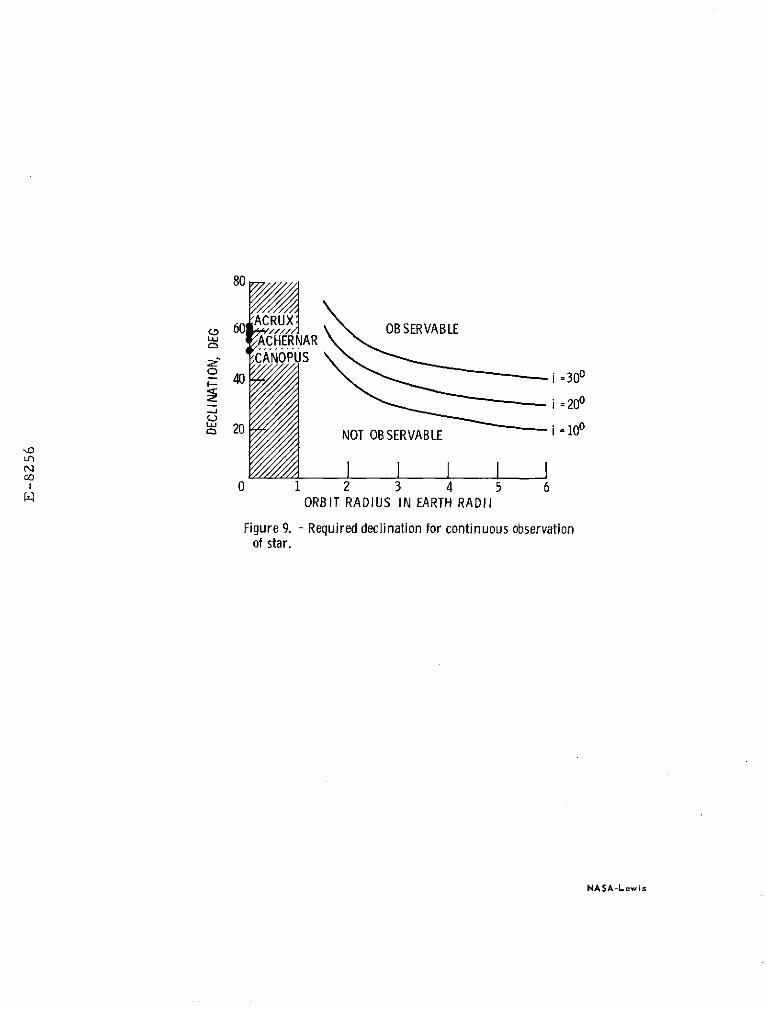
roll design is due to the reduction in power for rotates with respect to the centerbody. Other cen-the misalignment of the array from the sun line. In terbody locations such as the +Z and -Z faces wouldthe example given in the previous section (roll require more than one sensor for complete coverage.less than 200) the reduction in average power over One apparent suitable mounting location is on thethat orbit was 4%. As above, we can compare this tip of a deployed solar array. The sensor must beto a 40 kg reduction in payload, if this is the av- two-axis gimballed to maintain star contact duringerage power for the mission. Obviously, the power the thrust steering maneuvers. A sketch of such areduction for the entire thrust steering mode must mounting is shown in fig. 8. An additional problembe determined for an accurate comparison of design is the choice of suitable reference stars for lowoptions. altitude orbits. Fig. 9 shows the required star de-
clination to prevent earth occultation as a functionExamining actuation alone does not provide a of orbit radius and inclination. The problem of
complete basis for comparing the limited and unlim- earth occultation can be circumvented in two ways.ited design options. We will examine sensing re- First, an additional inertial reference may be pro-quirements in the next section. vided during occultation periods; or second, refer-
ence stars with large differences in right ascen-Sensing Tradeoffs sion can be used over different parts of the orbit.
The mass weight for the star tracker and gimbal sys-The purpose of this section is to examine in a tem is estimated at 14 kg. This is based on the
qualitative manner the tradeoffs which may be made ATM star tracker which has similar gimbal require-in selecting the prime sensing system for our ex- ments.ample mission. In particular, we will deal withthe thrust steering mode of operation. An inertial reference unit (IRU) has no mount-
ing problems. However, the IRU is generally lessFor three axis stabilization of any spacecraft, accurate than the optical sensors discussed above.
at least two non-parallel reference vectors must be This is because the IRU is subject to drift. Theknown by the control system. In discussions on IBU must be "updated" or recalibrated periodicallymodes of operation, we have indicated that one such using etternal sensors (sun and earth or star), andreference would be provided by sun sensors. For thus the IRU at best is no more accurate than theacquisition the sun sensors would be mounted on the sensors used for calibration. The estimated masscenterbody. Once the arrays are deployed, array weight of the IRU is 16 kg. This is based on themounted sun sensors can provide reference informa- minimum of representative hardware now in existance,tion. Assuming that the sun sensors provide one and includes the array mass weight required to gen-reference vector, then the second reference can be erate the IRU power of about 100 watts.provided by earth sensing, star sensing, or iner-tial reference system., These three sensing methods Unrestricted Roll Motion. In considering theor suitable combinations of them will be discussed large roll angles required for our example mission,for the limited and unlimited roll ACS design op- it is apparent that mounting change or additionaltions. As in the previous section payload penal- sensors are required for earth or star sensing. Toties for the methods of sensing will be determined maintain earth contact a single earth sensor wouldfrom the sensing system masses. be deployed from the +X face (payload area) of the
spacecraft. A 3600 gimbal would then be necessary.Limited Roll Motion. If roll motion is lim- For complete star tracker coverage, two sensors
gUGfNAL PAGE 1Sa POOR QJMfL
mounted on opposing arrays (fig. 8) are now neces- low altitude control energy expenditures. The ta-sary. The mass of the earth sensing system for this ble also shows that minimum penalties are associa-design option is estimated at 35 kg. The mass of ted with star sensing. This may or may not be sur-the star sensing system is estimated at 28 kg. No prising since the mass estimate for the earth andincrease in the IRU mass estimate is required. star sensing system were the largest for the current
hardware, and the mass estimate for the IMU wasTradeoffs. Again we will use the criterion of about the smallest for current hardware. With these
usable payload delivered to synchronous orbit in a estimates, it appears that there is little differ-fixed time. The basis is again the optimum mission, ence in sensing system choice for unlimited rollSun sensing is assumed to be part of the existing motion design, but for the limited roll motion de-spacecraft, therefore the payload penalties do not sign the earth and star sensing systems clearly costinclude sun sensing. The payload penalties for us- less in terms of payload penalty. Any reduction ining earth sensing are as given above at 20 kg for the star sensing or earth sensing systems mass es-limited roll motion and 35 kg for unlimited roll timates could make these systems more desirable formotion. The penalty for using star sensing is 14 kg the unlimited roll design option.for the limited roll motion design and 28 kg for theunlimited roll motion design. The penalty for us- A comparison of the subtables shows that theing the IRU is greater than the 16 kg mentioned unlimited roll design option payload penalties areabove. We should also include 14 kg for either a generally less than the penalties for the limitedstar tracker or a body fixed mounted earth sensor roll design option. Thus, the unlimited roll de-to be used with the sun sensors for IRU calibration, sign should deliver more useable payload to syn-
chronous orbit. The minimum values for each sub-The tradeoff as presented here is not complete table are for star sensing and 30 cm thruster ac-
in that weighing of system complexity is not made. tuation. A comparison of these minimum valuesThe earth sensor, for example, supplies roll and shows about a 20 kg advantage for the unlimitedpitch information directly for the limited roll mo- roll design option. This is about 2% of the basiction design. For this case, the star tracker does spacecraft mass. If we are now allowed to considernot supply roll and pitch information directly and the variation in flight time, the 2% payload penal-in addition presents the problem of having the sen- ty represents only a 4 to 5 day increase in a 200sor and actuator separated by a flexible array, day mission for a fixed mass payload. ReductionsDue to its mounting location the star tracker will in estimates of star and earth sensing systemssense not only the rigid body motions but the flex- masses would tend to make the unlimited roll designible motions of the array as well. Thus, care must more attractive; however, the payload penalties arebe taken in processing the star tracker data to not strong functions of the sensing systems masses.avoid undesirable or unstable ACS response. A If, for example, the star sensing systems mass wereweighing of such factors as these may be largely ignored, then we would be comparing payload penal-judgemental in nature and is not made here. ties of 42-46 kg for the limited roll design with
penalties of 10-30 kg for the unlimited roll de-sign. This represents an ultimate difference of
Concluding Remarks 32 kg or about 3% of the basic spacecraft mass.
We have examined separately the payload penal- We see, then, that a very real tradeoff existsties due to actuation and sensing for limited and between the ACS design options, the other spacecraftunlimited roll motion ACS designs. The actuation subsystems (thermal, power, etc.), and the missionpenalties, sensing penalties and power penalties performance represented by delivered payload. It isfor our example mission can be combined so that the apparent that additional effort can be expended tolimited and unlimited roll motion designs can be refine the payload penalties for the ACS design op-compared. The comparison is summarized in Table IV. -tions, and determine weighings for attitude controlThe first subtable is for the limited roll design and guidance and navigation systems complexity.option. The largest single penalty is due to the Such an effort would produce a realistic spacecraftdecrease in average power. A 4% reduction in power design for a geosynchronous transfer mission.was assumed from fig. 5, and the resulting payloadpenalty is 40 kg for our example spacecraft. Actu- Referencesator penalties are listed down the left side of the
subtable, and sensor penalties are listed along the 1. "Sert C Project Study," TM X-71508, 1974, NASA.top. The subtable, then, lists the total penaltydepending on the choice of sensor and actuator. A 2. Sharp, G. R., "A Thruster Sub-System Module
similar listing is presented for the unlimited roll (TSSM) for Solar Electric Propulsion," AIAA
design option. Remember that the total penalty is paper to be presented at the llth Electric
the reduction in useable payload delivered in a Propulsion Conference, New Orleans, La.,
fixed time. For our example mission the penalty is March 1975.
caused by the inclusion of sensing other than sun 3. Marsh, E. L., "The Attitude Control of a Flex-sensing, any reduction in net thrust due to de- ible Solar Electric Spacecraft," AIAA Papercreased power or 30 cm thruster gimballing, and the 70-1140, Stanford, Calif., 1970.control energy which must be expended during thethrust steering mode. 4. Marsh, E. L., "Attitude Stability of a Flexible
Solar Electric Spacecraft: A Parametric
The table shows that minimum penalties are as- Study," Journal of Spacecraft and Rockets,
sociated with the use of the 30 cm thrusters or the Vol. 11, No. 2, Feb. 1974, pp. 89-96.
small ion thrusters should they already exist for 5. Marsh, E. L., "Attitude Control of a Largestation keeping purposes. Note again, that the Flexible Spacecraft Using Three-axis Massauxiliary propulsion penalty and the 30 cm thruster Expulsion Control," AIAA Paper 73-893,penalty are worst cases since they were based on Key Biscayne, Fla., 1973.
7
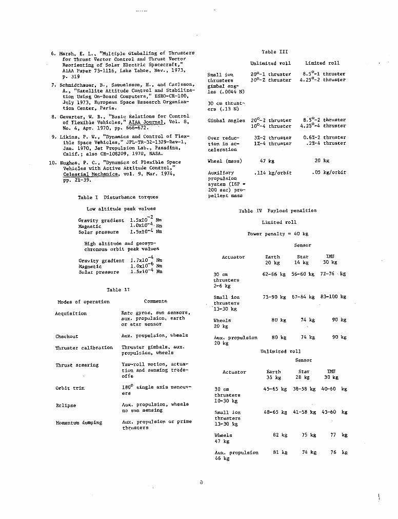
6. Marsh, E. L., "Multiple Gimballing of Thrusters Table III
for Thrust Vector Control and Thrust Vector
Reorienting of Solar Electric Spacecraft," Unlimited roll Limited roll
AIAA Paper 73-1116, Lake Tahoe, Nev., 1973,
p. 319 Small ion 200-1 thruster 8.50-1 thrusterthrusters 100-2 thruster 4.250-2 thruster
7. Schmidthauer, B., Samuelsson, H., and Carlsson, gimbal ang-A., "Satellite Attitude Control and Stabiliza- les (.0044 N)tion Using On-Board Computers," ESRO-CR-100,
July 1973, European Space Research Organiza- 30 cm thrust-tion Center, Paris. ers (.13 N)
8. Gevarter, W. B., "Basic Relations for Control
of Flexible Vehicles," AIAA Journal, Vol. 8, Gimbal angles 200-2 thruster 8.50-2 thruster
No. 4, Apr. 1970, pp. 666-672. 100-4 thruster 4.250-4 thruster
9. Likins, P. W., "Dynamics and Control of Flex- Over reduc- 3%-2 thruster 0.6%-2 thrusterible Space Vehicles," JPL-TR-32-1329-Rev-1, tion in ac- 1%-4 thruster .2%-4 thrusterJan. 1970, Jet Propulsion Lab., Pasadina, celerationCalif.; also CR-108209, 1970, NASA.
10. Hughes, P. C., "Dynamics of Flexible Space Wheel (mass) 47 kg 20 kg
Vehicles with Active Attitude Control,"Celestial Mechanics, vol. 9, Mar. 1974, Auxiliary .114 kg/orbit .05 kg/orbit
pp. 21-39. propulsionsystem (ISP =200 sec) pro-
Table I Disturbance torques pellent mass
Low altitude peak values Table IV Payload penalties-2
Gravity gradient 1.5x10 Nm Limited roll
Magnetic 1.0x10⁻⁴ Nm
Solar pressure .5x10- 4
Nm Power penalty = 40 kg
High altitude and geosyn- Sensorchronous orbit peak values
Gravity gradient 1.7x10 Actuator Earth Star IMU
Gravity gradient 1.7x1 Nm 20 kg 14 kg 30 kgMagnetic 1.0x10 NmSolar pressure 1.5xl0
4 Nm 30 cm 62-66 kg 56-60 kg 72-76 kg
thrusters
Table II 2-6 kg
Small ion 73-90 kg 67-84 kg 83-100 kgModes of operation Comments thrusters
13-30 kgAcquisition Rate gyros, sun sensors,
aux. propulsion, earth Wheels 80 kg 74 kg 90 kgor star sensor 20 kg
Checkout Aux. propulsion, wheels Aux. propulsion 80 kg 74 kg 90 kg
20 kgThruster calibration Thruster gimbals, aux.
propulsion, wheels Unlimited roll
Sensor
Thrust steering Yaw-roll motion, actua-tion and sensing trade- Actuator Earth Star IMUoffs 35 kg 28 kg 30 kg
Orbit trim 1800 single axis maneuv- 30 cm 45-65 kg 38-58 kg 40-60 kgers thrusters
Eclipse Aux. propulsion, wheels 10-30 kg
no sun sensing Small ion 48-65 kg 41-58 kg 43-60 kg
thrustersMomentum dumping Aux. propulsion or prime 13-30 kg
thrusters
Wheels 82 kg 75 kg 77 kg
47 kg
Aux. propulsion 81 kg 74 kg 76 kg46 kg
E-8256
ZI
SOLAR ARRAY
S XRYI
X ROLL r u I RZ YAW
1 (a) REFERENCE AXIS SYSTEM.PAYLOAD
ZR
ION ENGINES 4
YR
SOLAR ARRAY 1'- YAW
XR 41 8 -PITCH4en (p -ROLL
(b) SPACECRAFT ORIENTATION.
Y PITCH Figure 2.
Figure 1. - Spacecraft configuration.
I-JUNE21, r =0, SUN 3.5 0 ABOVE ORBIT PLANEII - MARCH 21, r =90, SUN 200 ABOVE ORBIT PLANE
200- MARCH 21 111- DEC. 21, r = 0 SUN 3.50 BELOW ORBIT PLANEIV- JUNE 21, r = 180, SUN 43.50 ABOVE ORBIT PLANE
r=0 200i=200
ARRAY ANGLE i
120 1
120 \ i = 200YAW MAX =300
40- ROLL ANGLE 80-
0
YAW ANGLE 0
-J-40-40
-80-120 -80
-120
I I I I I I I I I -160 -40 120 200 280 360
-200 IFigure 3. 0 40 80 120 160 200 240 280 320 360
ORBIT ARGUMENT, DEGFigure 4. - Roll motion.
I-ROLL=0 0 AVG. =89.96%II - ROLL 100 AVG. = 93. 44%
I -ROLL 200 AVG. =95.84%1.0-
0
, .8"' r = 1880o i =00
e-0DATE: AUG. 10
.6L I0 90 180 270 360
u IN DEG
Figure 5. - Power ratio as a function of orbit position and00 allowed roll angle.
G SIN p COSG = 3 00 (Iz- l y)
CONTROL('COMMAND K (t25 + 1) + + (ROLL
T3S + 1 2
SENSOR
I:2 S
K = 1. 76 NmlRAD 2 = 20T3
Figure 6. - Simplified roll control.
3. 0 -2
2. 5-
2.0 -
LIJI
70- 1. 5 m
I---E" 50 - 1. 0 -
ORBIT RADIUS =1.5 RE
I- MAX. TORQUES30 - .5 11- AVG. TORQUE
- H -MAX. MOMENTUM
100 .4 .8 1.2 1.6 2.0
MAX. ROLL ANGLE, RADIANS
Figure 7. - Torque and momentum requirements for roll con-trol.
SENSOR VIEW
-180
3600 SOLAR ARRAY
Figure 8. - Array mounted sensor.
80
ARUXS60 CRUX, OBSERVABLE
g ACHERNARCANOPUS
S40 i =300
i = 200
- 20 NOT OBSERVABLE i =10 0
0 1 2 3 4 5 6ORBIT RADIUS IN EARTH RADII
Figure 9. - Required declination for continuous observationof star.
NASA-Lewis