nasa technical note -- nasa tn d-6778 · nasa technical note -- nasa tn d-6778 c. / -” -i z 2...
TRANSCRIPT

-- N A S A TECHNICAL NOTE NASA T N D-6778 c./
-I” -2z
EVALUATION OF BORON-EPOXY-REINFORCED TITANIUM TUBULAR TRUSS FOR APPLICATION TO A SPACE SHUTTLE BOOSTER THRUST STRUCTURE
by Nicholus Corvelli and Robert Curri *‘ I’ i
Lungley Reseurch Center Humpton, Va. 23365
N A T I O N A L AERONAUTICS A N D SPACE A D M I N I S T R A T I O N W A S H I N G T O N , D. C. JUNE 1972 1 i4i
https://ntrs.nasa.gov/search.jsp?R=19720017292 2018-06-08T08:36:46+00:00Z

--
TECH LIBRARY KAFB, NM
IIllilllllll11111IIIIII IIll11lllllIll1Ill . .
4. Title and Subtitle 5. Report Date EVALUATION OF BORON-EPOXY-REINFORCED TITANIUM June 1972 TUBULAR TRUSS FOR APPLICATION TO A SPACE SHUTTLE 6. Performing Organization Code
BOOSTER THRUST STRUCTURE ~
7. Author(s1 8. Performing Organization Report No.
Nicholas Corvelli and Robert C a r r i L-8015 10. Work Unit No.
9. Performing Organization Name and Address 114-08-01-06 NASA Langley Research Center 11. Contract or Grant No. Hampton, Va. 23365
, 13. Type of Report and Period Covered 2. Sponsoring Agency Name and Address Technical Note
National Aeronautics and Space Administration -
I 5. Supplementary Notes
Authors were Langley-Industry Research Associates, now at Grumman Aerospace Corporation, Bethpage, N.Y.
_. -. __ 6 Abstract
Results of a study to demonstrate the applicability of boron-epoxy-composite-reinforced titanium tubular members to a space shuttle booster thrust structure a r e presented and discussed. The experimental results include local buckling of all-composite and compositereinforced-metal cylinders with low values of diameter-thickness ratio, static tests on composite-to-metal bonded step joints, and a test to failure of a boron-epoxy-reinforced titanium demonstration truss. The demonstration t russ failed a t 118 percent of design ultimate load. Test resul ts and analysis for all specimens and the t russ a r e compared. Comparing an all-titanium design and a boron-epoxy-reinforced-titanium (75 percent B-E and 25 percent Ti) design for application to the space shuttle booster thrust structure indicates that the latter would weigh approximately 24 percent less. Experimental data on the local buckling strength of cylinders with a diameter-thickness ratio of approximately 50 a r e needed to insure that undue conservatism is not used in future designs.
- - - _ _ -~ 7. Key Words (Suggested by Author(s)) 18. Distribution Statement
Boron- epoxy Composite-reinforced titanium Unclassified - Unlimited
Tubular t russ structure Space shuttle
- - 9. Security Classif. (of this report) 20. Security Classif. (of this page) I 21. N;;f Pages 22. *ice'
Unclassified Unclassified $3.00 - - - _ -

EVALUATION OF BORON-EPOXY-REINFORCED TITANIUM
TUBULAR TRUSS FOR APPLICATION TO A SPACE
SHUTTLE BOOSTER THRUST STRUCTURE
By Nicholas Corvelli* and Robert Carri* Langley Research Center
SUMMARY
Results of a study to demonstrate the applicability of boron-epoxy-compositereinforced titanium tubular members to a space shuttle booster thrust structure a r e presented and discussed. The experimental results include local buckling of all-composite and composite-reinforced-metal cylinders with low values of diameter-thickness ratio, static tests on composite-to-metal bonded step joints, and a test to failure of a boronepoxy-reinforced titanium demonstration truss. The demonstration t russ failed at 118 percent of design ultimate load. t russ a r e compared. Comparing an all-titanium design and a boron-epoxy-reinforced-
Test results and analysis for all specimens and the
titanium (75 percent B-E and 25 percent Ti) design for application to the space shuttle booster thrust structure indicates that the latter would weigh approximately 24 percent less. Experimental data on the local buckling strength of cylinders with a diameter-thickness ratio of approximately 50 a r e needed to insure that undue conservatism is not used in future designs.
cINTRODUCTION
The demand for increased structural efficiency in aerospace vehicles can be met by the use of relatively expensive, advanced composite materials. At the same time, the rising cost of aerospace vehicles dictates that composite materials be utilized in the most effective manner. One approach which appears to offer the potential of meeting this goal is a composite-reinforced-metal concept reported in reference 1. In reference 1, it was shown that the structural efficiency of a metal tube loaded in axial compression can be increased substantially by bonding composite material to the exterior surface of the tube. The weight savings obtainable through increased structural efficiency and the unit costs of that weight savings a r e dependent upon the amount of composite material used. In the - . * Langley-Industry Research Associate, now at Grumman Aerospace Corporation,Bethpage, N.Y.

design, the percentage of composite reinforcement utilized would depend upon the acceptable unit cost of any weight savings for the particular vehicle application. In the study reported herein, a segment of a 1/3-scale thrust structure which included two boronepoxy-reinforced titanium tubular members and a lightweight titanium joint cluster was designed and tested. The results were extrapolated to predict the weight savings of a boron-epoxy-reinforced titanium t rus s compared with that of an all-titanium design.
The research effort was performed by Grumman Aerospace Corporation engineers assigned to the Langley Research Center under the Langley-Grumman Research Associate Program. Overall program guidance, hardware manufacture, and test support were provided by Langley Research Center personnel.
SYMBOLS
The units for the physical quantities defined in this paper a r e given both in the International System of Units (SI) and the U.S. Customary Units. The measurements and calculations were made in U.S. Customary Units. Conversion factors relating the two systems a r e given in reference 2, and those pertinent to the present investigation a r e presented in appendix A.
A
D
E
G~~
K
L
M
M1'M2
P
r
2
column cross-sectional area, meters2 ( inched)
mean diameter of tube, meters (inches)
Young's modulus, newtons/meter2 (pounds force/inchZ)
shear modulus in the longitudinal-transverse plane, newtons/meterZ (pounds force/inch2)
factor defined by equation (C4)
column length, meters (inches)
moment in column, newton-meters (pound force-inches)
end moments on column, newton-meters (pound force-inches)
axial load, newtons (pounds force)
mean radius of tube, meters (inches)

t
01
P
Y
"LT, "TL
'
'C
Ocol
Ocr
'e
@
tube wall thickness or layer thickness, meters (inches)
filament orientation angle, measured from axis of tube, radians (degrees)
stress ratio defined by equation (C8)
theory-experiment correlation factor (see eq. (C3))
major Poisson's ratio and minor Poisson's ratio, respectively
axial s t ress , P/A, newtons/metera (pounds force/incha)
critical column buckling s t ress , newtons/metera (pounds force/inch2)
optimum column s t ress , newtons/meter2 (pounds force/incha)
critical local buckling s t ress , newtons/metera (pounds force/inch2)
Euler buckling s t ress , newtons/metera (pounds force/inch2)
factor defined by equation (C5)
Subscripts:
cal calculated
exP experimental
L longitudinal direction of laminate or lamina
max maximum
T transverse direction of laminate o r lamina
SPACE SHUTTLE BOOSTER THRUST STRUCTURE
A model of the space shuttle booster thrust structure selected for use in this study and the location of the structure in the launch vehicle a r e illustrated in figure 1. The t russ configuration had been chosen by the Marshall Space Flight Center for use in an earlier cost-weight study. The t russ is built up from a ser ies of planar sections and is
3

approximately 11m (36 ft) in diameter and 3 m (10 ft) deep. Loads from the nine engines a r e applied at the intersections at the bottom of the t russ and transmitted through the members to the eight fuselage reaction points located around the circumference at the top of the structure. Two t russ members and a connecting joint, labeled 'Demonstration Truss Components" in figure 1, were selected for detailed design and analysis. In order to limit cost and facilitate fabrication and test, it was decided that the demonstration t russ would be a 1/3-scale model.
The structural efficiency of a t russ such as that shown in figure 1is strongly dependent upon the designs of the joint clusters. Two types of connectors, tubular intersection and lug, were considered for the present study. The tubular-intersection connector provides a rigid end connection that is capable of reacting moments. However, final assembly of a three-dimensional t russ with this type of connector for each member could be difficult to accomplish since all members would have to be slipped over the connectors. Alternatively, a lug design offers the more promise for a machined par t fitting and for facilitating assembly. A joint cluster utilizing this type of connector could not, however, have all load lines intersecting at a common point since it would be unstable for an applied moment to the fitting. A combination of the two joining concepts, shown in figure 2, appears to offer the most potential for fabrication and assembly of the full-size three-dimensional t russ . Accordingly, the joint cluster for the demonstration t russ was designed with a lug fitting for the tension member and a tubular connection to the compression member.
A 1/3-scale model of the vertical planar t russ which contains the demonstration t russ components is shown in figure 3, together with the primary internal load distributions for the engines in the symmetric and gimbaled configurations. To account for scaling, the loads given in figure 3 a r e 1/3 those for the full-scale truss.
DESIGN AND ANALYSIS
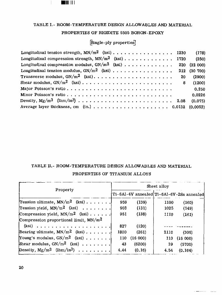
The basic tubular members of the demonstration t russ were designed for ultimate load, defined as 1.5 times limit load, with a zero o r slightly positive margin of safety. The tubular members were designed with approximately 75 percent boron-epoxy and 25 percent titanium by volume. Selection of this volume ratio was based on the cost-weight analysis presented in appendix B, which indicates that a further increase in volume of composite would result in a minimal additional weight reduction. In addition, it was anticipated that this high ratio of composite to metal would exhibit the potential problem areas associated with this design concept. Fittings and joints, both bolted and bonded, were designed for a margin of safety of 15 percent at ultimate load. No yielding was permitted at 1.15 times limit load. Material allowables for the boron-epoxy and titanium alloys a r e included in tables I and 11, respectively.
4

The geometrical parameters of the tubular compression member were obtained from the optimization analysis discussed in appendix C. The member was analyzed as a beam column with applied axial load and end moments. The geometric proportions of the compression member were optimized such that the resulting minimum-weight tube was critical in local buckling. The cylinder wall was assumed to be composed of a homogeneous orthotropic material for the local buckling analysis (ref. 3). After transforming the homogeneous design into one with discrete layers, the margin of safety was determined by using the local buckling analysis of reference 4 which includes the effects of the inhomogeneity of the orthotropic laminated tube wall. In cases where the analysis of reference 4 showed a negative margin of safety, arbitrary modifications were made to satisfy strength criteria. For both calculations, a correlation factor was included as a reduction of the theoretical buckling stress. Due to the high stiffness and strength of the boron-epoxy composite, optimized compression tubes have a configuration with low values of the diameter-thickness ratio D/t. For this study the ratio was approximately 50. This range is not of practical interest for metallic tube design and, as a result, cylinder buckling test data in this range are deficient. In reference 5, a curve of the correlation factor as a function of r/t extrapolated into the region of interest indicates a correlation factor of 0.79. Due to the scarcity of available test data in the region of interest for this application, a value for the correlation factor w a s based upon the results of cylinder tests performed in this program and presented in appendix D. A value of 0.6 was used.
Tension members were designed for ultimate strength based on the allowables presented in tables I and 11. Failure of the member was assumed to occur when the allowable s t r e s s of the axial plies was obtained.
The stepped bonded joints for the tension and compression members were designed by using an analysis presented in reference 6. This analysis neglects the tension s t resses in the adhesive; however, it should be adequate for symmetric bonded joints where bending is negligible. For the tubular members, although the bonded joints a r e unsymmetric, the adhesive tension stresses are neglected and all out-of-plane bending is assumed to be balanced by hoop loads. In addition, the effect of the adhesive layers between the metal shims is neglected. The titanium joint cluster was designed as a lightweight structural component. The tubular connection w a s sized to mate with the compression member and the lug was designed by using the method described in reference 7.
TEST SPECIMENS
Demonstration Truss
The demonstration t russ shown in figure 4 includes a 104-cm (41-in.) compression member, a 64-cm (25-in.) tension member, and a joint cluster machined from Ti-6A1-4V annealed. To facilitate loading, the demonstration t russ was rotated so that the resultant
5

I I I111111111ll111llllI
applied load was vertical. The angle between the compression and tension members of the demonstration t rus s is identical to that of the model. Both the compression and tension tubular members consist of three sections, as follows:
(1)A uniform section of thin-walled Ti-6Al-4V annealed seam-welded tube reinforced with boron-epoxy
(2) A transition region which utilizes a stepped-joint concept to transfer loads from the composite to the titanium end fittings
(3) End fittings which a r e mechanically fastened directly to the joint cluster for compression members or which terminate as lugs for tension members
Figure 5 shows the internal load distribution used to design the structure, including the secondary loading induced by the displacement of the structure under load. The secondary loads, which include an end moment of 6380 N-m (56.5 kip-in.), serve to demonstrate the moment-carrying capability of the tubular reinforced members. This capabili ty is a design requirement of the shuttle structure for the applied-load cases with the engines in the gimbaled position.
The compression member of the demonstration t russ shown in figure 6 consists of 16 layers of boron-epoxy (14 longitudinal, one at 0.785 rad (45O), and one at -0.785 rad) on a Ti-6A1-4V annealed tube having a 9.1-cm (3.6-in.) 0.d. and a 0.066-cm (0.026-in.) wall. Five additional plies of boron-epoxy a r e contained in the transition region to obtain a 15-percent margin of safety. The end fittings of the tube a r e rolled sheet stock chemmilled to final dimensions. Each of the shims shown in figure 6 is split at one point around the circumference. For assembly, the shims were expanded slightly and slipped into position over the boron-epoxy and film adhesive. The discontinuities in the shims were staggered around the tube.
The tension member of the t russ (fig. 7) was fabricated by curing 18 layers of boron-epoxy (16 longitudinal, one a t 0.785 rad (45O), and one a t -0.785 rad) on a Ti-6A1-4V annealed tube having a 5.1-cm (2.0-in.) 0.d. and an 0.084-cm (0.033-in.) wall. The titanium substrate was butt-welded to machined end fittings prior to the addition of the boron-epoxy.
Subelement Specimens
Three elements were designed for fabrication and test prior to manufacturing the demonstration t russ in order to verify experimentally the basic design and analysis of the stepped joint transition region. The tension specimen is identical to the tension member of the demonstration t russ shown in figure 7. The compression subelement shown in figure 8 was selected to demonstrate the joint concept for the all-composite design discussed in appendix B. The compression subelement shown in figure 9 was selected to
6
verify the joint concept for the 75 percent boron-epoxy, 25 percent titanium member of the demonstration truss. The stepped shim joints for the all-composite tube were fabricated from Ti-6A1-6V-2Sn annealed. This higher strength alloy was used instead of Ti-6Al-4V annealed because no welding was required for this design.
Three precautions were taken against bearing failure of the,boron-epoxy at the end of the compression specimens, as shown in figures 8 and 9. First, three longitudinal plies of boron-epoxy were added to the end of the specimens to reduce the bearing s t ress . Second, a 0.5-cm- (0.2-in-) thick tapered tab, 2.5 cm (1.0 in.) long, of circumferential-wrapped unidirectional fiber glass was located at the end of the tube. Finally, the inside of the specimens was filled with epoxy potting compound to a depth of 1.3 cm (0.5 in.). Load introduction at the opposite, all-titanium, end of the subelement was accomplished with two rows of bolts which a r e similar to those of the demonstration truss. Photographs of the two compression subelements a r e shown in figure 10.
SPECIMEN FABRICATION
The composite- tube fabrication procedures represent a modification to a process developed at Langley Research Center (ref. 8) which utilizes a heat-shrinkable teflon sleeve over the composite and an oven cure. After considerable development effort, a fabrication procedure which includes a bleeder system and autoclave curing was selected for the manufacture of specimens.
The boron-epoxy prepreg was laid up on the titanium substrate for the composite-reinforced specimens and directly on a male mandrel for the all-composite specimens. Additional resin was added to the inside of the first ply to decrease the porosity and improve the tack. This additional resin also increases the strength of the bond to the titanium substrate. Each ply was laid in place with the scr im cloth down and w a s manually compacted. The composite laminate was covered with a thin-weave nylon peel ply and heat-shrinkable nylon bleeder plies, as required for the particular laminate. This entire package was bagged with a heat-shrinkable teflon sleeve and cured in an autoclave by drawing a vacuum through the bleeder system and using the manufacturer's recommended cure cycle. Composite tubes thus processed exhibited approximately a 0.50 filament volume fraction and a uniform wall thickness.
During manufacturing-process development efforts, it was discovered that transverse residual s t resses could cause longitudinal cracks to develop in the composite material of the reinforced tube wall. These residual s t resses result from the required elevated temperature cure of the composite and the dissimilarities of the constituent material coefficients of thermal expansion. Tubes with 75 percent composite by volume experienced critical residual s t resses . Subsequently, composite-reinforced specimens were
7

designed with a pair of plies at 0.785 rad (45O) on the exterior surface of the composite. These layers reduced the residual s t resses and increased the circumferential strength of the boron-epoxy laminate.
The titanium substrate for the composite-reinforced specimens was rolled and seam-welded Ti-6Al-4V annealed sheet stock. The welding process involved tungsten inert-gas fusion welding without the addition of filler rod material. The joint cluster was machined from a rolled billet of Ti-6A1-4V annealed material.
METHOD OF TESTING
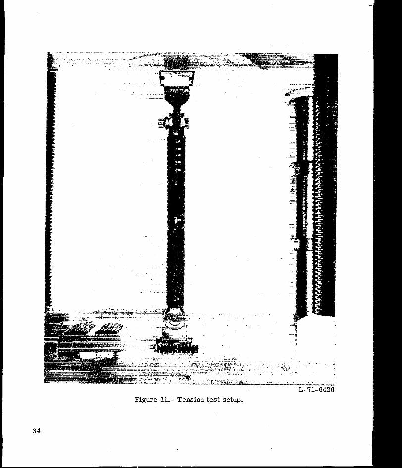
The subelement specimens were tested in a 1340-kN- (300-kip-) capacity hydraulic test machine. Hardened steel disks were used between the test specimen and the machine platen for load introduction directly into the boron-epoxy composite in bearing. Pr ior to testing, the specimen was loaded to 20 percent of its anticipated failing load and the platen was alined to obtain an equal strain readout from the four gages placed around the circumference of the specimen. The tension element was tested as shown in figure 11.
The demonstration t russ was tested by using a 1340-kN- (300-kip-) capacity portable hydraulic test machine as shown in figure 12. The t russ was mounted on a vertical rigid wall and loaded directly under the joint cluster with a vertical load applied by the jack. A system of rol lers was used to permit horizontal and rotational motion in the plane of the t russ at the load introduction point. The out-of-plane deflection of the joint cluster was restricted with tension cables (not shown in the figure) oriented perpendicular to the plane of the t russ and anchored to the support wall. The demonstration t russ was loaded to approximately 50 percent of design ultimate load at a load rate of 134 kN (30 kips) per minute and then unloaded. Strain-gage outputs were checked to verify that the desired internal load distribution had been obtained. The demonstration t russ was then loaded to failure at the same load rate.
Foil strain gages were located on all specimens as required to determine s t ra in distributions and to help detect buckling of the compression specimens. The strain-gage data were recorded during test with the use of the Langley central digital data recording facility. All specimens were loaded at a constant load rate to failure. The load rate used for each particular specimen was that which corresponded to an initial strain rate of 0.001 per minute. All testing was conducted at room temperature.
TEST RESULTS AND DISCUSSION
Subelement Specimens
The design ultimate load, the experimental failure load, and the specimen parame ters a r e presented in table III for all the compression subelements and the tension ele
a

I
ment. The all-composite compression subelement failed at 734 kN (165 kips) o r 93 percent of design ultimate load. The failure occurred in the transition region and resulted from the buckling of the outermost titanium shim at its discontinuity. It appears that an overall increase in the titanium thickness of the tube end or a reapportionment of the internal shim thicknesses to reduce the degree of discontinuity in the external shim could improve this situation. Efforts along these lines were not pursued in the present study because shim buckling was considered unlikely for the composite-reinforced designs which a r e of primary interest. Because of its lower compressive yield s t ress , the titanium alloy used in the composite-reinforced designs is not s t ressed to the level at which this shim buckled.
The first composite-reinforced compression subelement failed at 687 kN (155 kips) or 87 percent of design ultimate load. This failure occurred at the end of the specimen by brooming of the fibers. This test was repeated with a new specimen and it failed at 653 kN (147 kips). The onset of buckling of the titanium substrate occurred a t a load of 490 kN (110 kips). An inadequate bond between the boron-epoxy and the titanium resulted in the premature failure. Investigation revealed that this specimen was fabricated without additional epoxy resin under the first ply. Although these specimens failed to meet the ultimate load requirement, analysis of the modes of failure established sufficient confidence in the design and fabrication procedures to warrant suspension of further subelement tests.
The tension element failed at 603 kN (136 kips) or 113 percent of design ultimate load. The failure occurred a t the center section of the member away from the bonded-joint transition regions as shown in figure 13. This location of failure was anticipated due to the higher margins of safety utilized in the transition regions and end-fitting designs. The failure occurred at a s t r e s s level of 1190 MN/m2 (163 ksi) in the tube wall.
Axial strains along the transition regions of the compression and tensile specimens a r e compared with s t ra ins calculated by use of the analysis of reference 6 in figures 14 and 15, respectively. There is good agreement between the calculated and experimental strains for all the subelement tests. This agreement shows that the assumption of negligible bending in the joint region is applicable. In addition, for the compression specimen in which the multiple-shim stepped joint was used, the test results demonstrate that the effects of the bondlines between the shims a r e negligible as was assumed in the analysis.
Demonstration Truss
The demonstration t russ failed at a load of 917 kN (206 kips), 118 percent of design ultimate load. Failure occurred in the center section of the tension member as shown in
9

I I 1111Ill Ill Ill11l1l1l II
figure 16. A tension failure of the composite material probably initiated the fracture and debonding between the boron-epoxy and the titanium substrate. It is unlikely that the failure started in the titanium, because it was s t ressed to less than 80 percent of i t s ultimate stress. The failure continued through the titanium substrate at a location near the butt weld. This mode of failure was similar to that of the tension element (fig. 13). After testing, a visual inspection revealed no evidence of failure in the compression member or the joint cluster. Strain-gage data recorded during the test indicate that the compression member had been loaded to 113 percent of design ultimate load.
Projected Weight Saving
Weight estimates for a full-size planar t russ of the configuration shown in figure 3 a r e included in table IV for an all-titanium design and a boron-epoxy-reinforced-titanium design. Both the titanium and the boron-epoxy-reinforced titanium tubular members were designed by utilizing the procedures previously described. The composite-reinforced members had a basic section of 75 percent boron-epoxy and 25 percent titanium by volume, similar to those of the demonstration truss. The weights of end fittings required to attach the composite-reinforced tubular members to joint clusters a r e included in the member weights listed in table IV and were estimated by scaling up the appropriate designs of the demonstration truss. End-fitting weight was assumed to be directly proportional to the member load raised to the three-halves power. This scaling factor was derived by noting that the required cross-sectional a reas of the fasteners and end fittings a r e directly proportional to the member load, whereas the end-fitting length required to prevent shear out of the fasteners is proportional to the square root of the member load. The titanium compression members were uniformly welded tubes with no additional material needed for load introduction and, therefore, included no end fitting. The joint cluster weights were estimated by using the basic design of the test-article joint cluster. These weights were then scaled up for load and to account for interference problems associated with larger diameter members. Fastener weights a r e included in the joint cluster weights.
A weight saving of 96.8 kg (213 lbm) was calculated for the members. An additional saving of 18.3 kg (40lbm) is shown for the joint clusters. This saving results f rom the composite-reinforced designs being of a smaller diameter than the optimum titanium compression members and therefore requiring smaller connectors. The total weight saving for the full-scale planar t russ amounts to 24 percent of the t russ weight. It is expected that a similar weight saving could be achieved on the entire booster thrust structure.
10

CONCLUSIONS
An analytical and experimental study has been conducted to demonstrate the weight-saving potential of composite-reinforced titanium tubular members for a space shuttle booster thrust structure. Results of the study showed that:
1. Development tests of subelements based on preliminary design are essential to insure satisfactory performance of the final, detailed design.
2. The addition of a pair of angle plies to the outside of the longitudinally oriented boron-epoxy reinforcement of a titanium tube was found to prevent laminate cracking caused by transverse residual curing stresses.
3. Addition of a res in o r adhesive layer between the boron-epoxy prepreg and the titanium substrate tube was found to decrease joint porosity and increase bond strength.
4. A multiple-shim, multiple-step joint concept provided a satisfactorily designed transition region for transferring loads from the boron-epoxy composite to the titanium end fittings.
5. Additional experimental data on the local buckling strength of cylinders with diameter-thickness ratios in the range of interest for highly loaded, optimum-design composite cylinders (D/t =: 50) are needed for efficient design. The limited tests in this study failed prematurely due to improper end constraints with no indication of local buckling at an experimental/theoretical correlation factor of 0.58.
6. Results of the subelement and local buckling tests have been applied to the design of a heavily loaded, composite-reinforced metal tubular t ru s s structure. Comparative designs indicated that the composite-reinforced titanium t rus s weighed 24 percent less than an equivalent all-titanium truss.
7. A demonstration t russ with one compression member and one tension member of boron-epoxy-reinforced titanium and an interconnecting titanium joint cluster was designed, fabricated, and tested. Failure occurred in the tension member at 118 percent of design ultimate load.
Langley Research Center , National Aeronautics and Space Administration,
Hampton, Va., April 26, 1972.
11

APPENDIX A
CONVERSION OF U.S. CUSTOMARY UNITS TO SI UNITS
The International System of Units (SI) was adopted by the Eleventh General Conference on Weights and Measures, Paris, October 1960, in Resolution No. 12 (ref. 2). Conversion factors for the units used herein are given i n the following tables:
- - --
Physical quantity U.S. CustomaryUnit
Conversion factor SI Unit
(*) ~~
Angle degrees 1.745 x 10⁻² radians (rad) Bending moment kip-in. 1.130 x 10² newton- meters (N-m) Density lbm/in3 2.768 x lo4 kilograms per cubic meter (kg/m3) Force kip = 1000 lbf 4.448 x lo3 newtons (N) Length in. 2.54 x meters (m) Mass lbm 4.536 x 10⁻¹ kilograms (kg) Moduli and stress ksi = kips/in2 6.895 x lo6 newtons per square meter (N/m2)
* _ _ - _ _ - -. --.
Multiply value given in U.S. Customary Unit by conversion factor to obtain equivalent value in SI Unit.
Prefixes to indicate multiple of units are as follows:
12
.... .

APPENDIX B
COST-WEIGHT COMPARISON OF BORON-EPOXY-REINFORCED
TITANIUM TUBULAR COLUMNS
The composite-reinforced tubular concept investigated in this study offers to the designer a variable weight saving which is dependent upon the percentage of composite material used. As the percentage of composite is increased, both the weight saving and the unit cost of that weight saving are increased. The relation between cost and weight is shown in figure 17 for a typical compression member designed as a uniform boronepoxy-reinforced titanium tube. The slope of the curve presented in figure 17 shows the incremental cost for each successive increment of weight saved. Note that the application of a small percentage of boron-epoxy reinforcement is extremely efficient i n te rms of weight saved per pound of boron-epoxy used. At the other extreme, for high percentages of reinforcement, the last increments of weight savings that are achievable a r e quite costly.
The composite-reinforced columns represented in figure 17 were designed with boron-epoxy reinforcement on the outside of a titanium tubular substrate. For comparison purposes an all-composite column was included in the figure. Manufacturing costs were determined on a production-cost basis by using the costs shown in figure 17.
Two families of laminate orientations for the wall of the all-composite compression tube were investigated to determine the lowest weight design. For each orientation the optimization procedure of appendix C was used to determine the critical stress corresponding to the minimum-weight design. This s t r e s s is plotted in figure 18. The f i rs t family of laminates investigated included longitudinal plies and plies oriented at angles of k0.785 rad (k45O) and 1.57 rad (goo) to the axis of the tube. The results of this investigation a r e shown in figure 18(a). The sharp breaks in the curves result from a change in the mode for local buckling. The minimum-weight design is shown to have approximately 60 percent of the plies longitudinal and 40 percent of the plies oriented at k0.785 rad (k45O) to the axis of the tube. The second family of laminates was investigated to determine whether the design could be improved by varying the orientations of the angle plies. The results a r e shown in figure 18(b). The flatness of these curves in the a rea of maximum stress indicates that columns of approximately equal weight could be designed with different angle-ply orientations. The laminate orientation selected for use in the cost-weight study consists of 60 percent longitudinal plies and 40 percent k0.785 rad (k45O) plies.
13

APPENDIX C
COMPRESSION TUBE OPTIMIZATION
The problem of optimizing the configuration of a tubular member which is subject to axial load only (column) or to axial load and bending moment (beam column) was solved in this study for homogeneous orthotropic materials. The beam column configuration and loading is shown in figure 19. This optimization was used to design all compression members (titanium, boron-epoxy-reinforced titanium, and boron-epoxy).
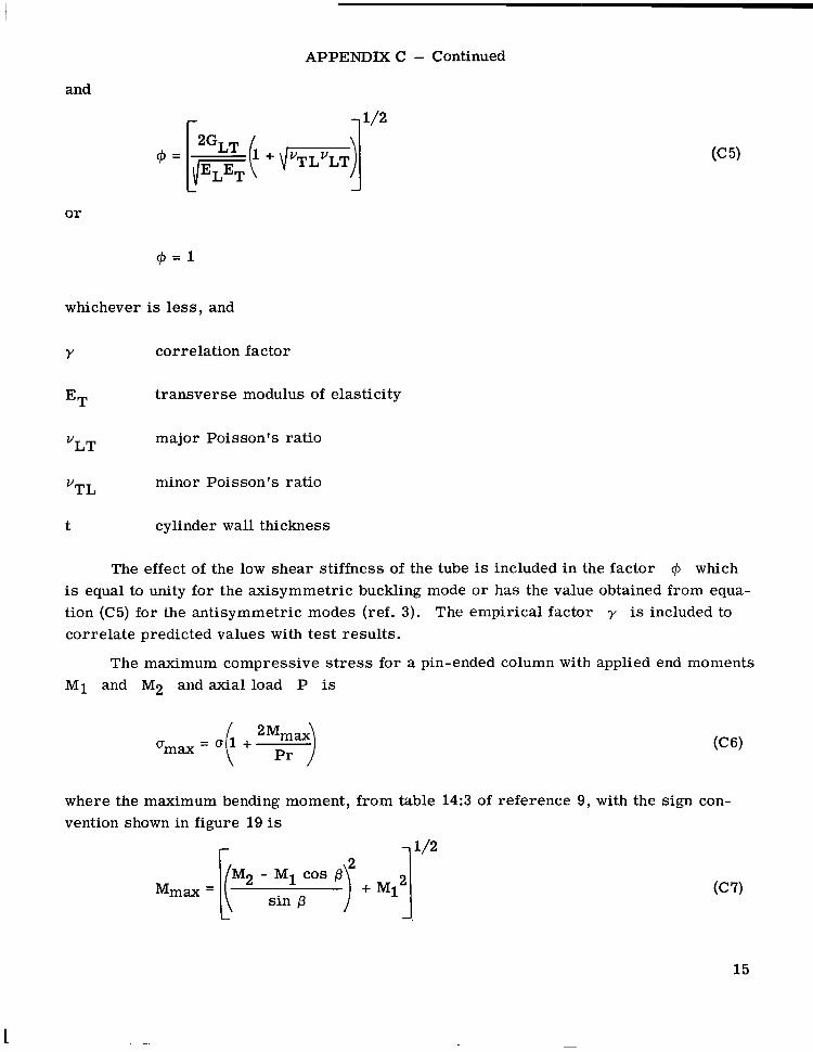
The critical buckling s t r e s s for overall (column) instability, including the shear deflection term, with both ends simply supported is
where
Lr2 ( J =e
2L2
and
G~~ in-plane shear modulus
EL longitudinal modulus of elasticity
r mean radius
L tube length
The local buckling s t r e s s for circular cylindrical tubes (refs. 3 and 5) is
where
-1/2
14
APPENDIXC - Continued
and
or
whichever is less, and
Y correlation factor
ET transverse modulus of elasticity
YLT major Poisson’s ratio
minor Poisson’s ratioV~~
t cylinder wall thickness
The effect of the low shear stiffness of the tube is included in the factor 4 which is equal to unity for the axisymmetric buckling mode o r has the value obtained from equation (C5) for the antisymmetric modes (ref. 3). The empirical factor y is included to correlate predicted values with test results.
The maximum compressive s t r e s s for a pin-ended column with applied end moments M1 and M 2 and axial load P is
= + “;a)
where the maximum bending moment, from table 14:3 of reference 9,with the sign convention shown in figure 19 is
f
15

I I I I 1ll111111lllIIIlll11111
APPENDIX C - Continued
where
cr=-P A
and A is defined as the column cross-sectional area.
By use of the definition of the nominal stress cr, the Euler buckling s t ress can be written
Solving equation (C3) for r/t and substituting into equation (C10) gives
and the column buckling s t r e s s (eq. (Cl)) can be written as
r 1 - 1
Substituting equation (C12) into the definition for p gives
f r 711'2
Solving for the mean radius of the tube with equation (C3) and the definition of the nominal s t r e s s gives
16

APPENDIX C - Concluded
Substituting into equation (C6) gives
M2 - M1 cos p)” + M1jl’] (C15)
sin p
with p being given by equation (C13).
The minimum-weight beam column is now found by setting the maximum applied stress umax equal to the local buckling s t r e s s ucr. Equation (C15) is now a single relation between u and ucr which is used to search for the maximum value of u by varying Ucr. The range of variation of Ucr which must be searched is bounded by the value of Ucr associated with the optimum column and the compression ultimate s t ress . The local buckling s t r e s s for the optimum column (Tcr is found by equating the nominal s t r e s s to the local buckling s t ress and the column buckling s t r e s s
. Therefore, p is set equal to 71, and equation (C15) is no longer applicable. The optimum column is found by solving the following equation for ucol:
Once the maximum value of u and the related value of ucr a r e found, the geometrical configuration of the tube can be found from equation (C14) and A = P/o.
A computer program using this procedure has been written which yields the configuration of the optimum tube and of other tubes that a r e near optimum. These additional configurations enable the designer to vary the tube design parameters which affect the weight of other structural components, particularly the joint clusters. In this manner the designer can achieve a near -optimum structural configuration.
17

I I I111111II I I I1
APPENDM D
CYLINDER BUCKLING TESTS
In order to establish a correlation between theoretical and experimental data on cylinder buckling for a low D/t range, the following cylinder buckling test program was utilized. Five basic tubular buckling specimens were fabricated for axial compression tests. Geometrical parameters and laminate orientation for each specimen a r e included in table V. All specimens were designed with small L/D values (1to 3.6) to insure failure in the local buckling mode.
Two of the specimens fabricated were 10 cm (4 in.) in length, one all-composite and one composite-reinforced titanium which is shown in figure 20. Three additional 33-cm(13-in-) long composite-reinforced titanium specimens were also fabricated. These specimens (fig. 21) were designed with a greater length in an attempt to obtain buckling failures away from the ends of the cylinders where the effects of the supports and rotational restraints a r e most marked. The precautions taken against bearing failure of the subelement specimens (i.e. , fiber-glass tabs, potting, and additional plies) were also included in the design of all the local buckling specimens.
The local buckling specimens were tested in a 1340-kN- (300-kip-) capacity hydraulic test machine by using the procedure described previously. The test setup is shown in figure 22.
Typical strain-gage data a r e presented in figure 23 for both a 10-cm (4-in.) and a 33-cm (13-in.) composite-reinforced specimen. The data for the 10-cm specimen indicate that bending was present in the test section from the onset of loading whereas the data for the 33-cm cylinder shows no evidence of bending in the center of the test section. The failure of the longer specimens began at the edge of the fiber-glass tabs and was attributed to the presence of bending moments at the tube ends. This bending is shown in the strain-gage readings at the tab edge (fig. 23) and the failure, as shown in figure 24, is an end failure. The test data for these longer local buckling test specimens (table V) show an average correlation factor of 0.58. Since these failures occurred prior to buckling of the test section, and the strain-gage data indicated that a local buckling failure was not imminent, this correlation factor is expected to be too low. The value given in reference 5 for the appropriate value of D/t is 0.79. The compression member of the demonstration t russ was designed with a correlation factor of 0.6.
18
REFERENCES
1. Zender, George W.; and Dexter, H. Benson: Compressive Properties and Column Efficiency of Metals Reinforced on the Surface With Bonded Filaments. NASA T N D-4878, 1968.
2. Comm. on Metric Pract.: ASTM Metric Practice Guide. NBS Handbook 102, U.S. Dep. Com., Mar. 10, 1967.
3. DOW,Norris F.; and Rosen, B. Walter: Structural Efficiency of Orthotropic Cylindrical Shells Subjected to Axial Compression. AIAA J., vol. 4, no. 3, Mar. 1966, pp. 481-485.
4. Card, Michael F.: Experiments To Determine the Strength of Filament-Wound Cylinders Loaded in Axial Compression. NASA TN D-3522, 1966.
5. Anon.: Buckling of Thin-Walled Circular Cylinders. NASA SP-8007, 1965. (Revised 1968.)
6. Corvelli, N.; and Saleme, E.: Analysis of Bonded Joints. Rep. No. ADR 02-01-70.1, Grumman Aerosp. Corp., July 1970.
7. Bruhn, E. F.: Analysis and Design of Flight Vehicle Structures. Tri-State Offset Co., c.1965.
8. Davis, John G., Jr.: Fabrication of Uniaxial Filament-Reinforced Epoxy Tubes for Structural Applications. Advanced Techniques for Material Investigation and Fabrication, SAMPE Vol. 14, SOC.Aerosp. Mater. Process Eng., c.1968.
9. Ni les , Alfred S.; and Newell, Joseph S.: Airplane Structures. Vol. 11, Third ed., John Wiley & Sons, Inc., c.1943, p. 94.
19
I
---- -------
--
I ll11111111I1lIIIII I1
TABLE I.- ROOM-TEMPERATURE DESIGN ALLOWABLES AND MATERIAL
PROPERTIES OF RIGIDITE 5505 BORON-EPOXY
@ingle-ply propertied
Longitudinal tension strength, MN/m2 (ksi) . . . . . . . . . . . . . . . . 1230 (178) Longitudinal compression strength, MN/m2 (ksi) . . . . . . . . . . . . . 1720 (250) Longitudinal compression modulus, GN/m2 (ksi) . . . . . . . . . . . . . 220 (32 000) Longitudinal tension modulus, GN/m2 (ksi) . . . . . . . . . . . . . . . . 212 (30 700) Transverse modulus, GN/m2 (ksi). . . . . . . . . . . . . . . . . . . . . 20 (2900) Shear modulus, GN/m2 (ksi) . . . . . . . . . . . . . . . . . . . . . . . . 8 (1200) Major Poisson's ratio . . . . . . . . . . . . . . . . . . . . . . . . . . . . 0.2 50 Minor Poisson's r a t io . . . . . . . . . . . . . . . . . . . . . . . . . . . . 0.0226 Density, Mg/m3 (lbm/in3) . . . . . . . . . . . . . . . . . . . . . . . . . 2.08 (0.0 75) Average layer thickness, cm (in.) . . . . . . . . . . . . . . . . . . . . 0.0132 (0.00 52)
TABLE II.- ROOM-TEMPERATURE DESIGN ALLOWABLES AND MATERIAL
PROPERTIES OF TITANIUM ALLOYS
r .
Sheet alloyProperty ~~ -. ~
Ti- 6Al-4V annealed Ti-6Al-6V-2Sn annealec -. . . ._ .- . - . . -_
Tension ultimate, MN/m2 (ksi) . . . . . . . 959 (139) 1100 (160) Tension yield, MN/m2 (ksi) . . . . . . . . 903 (131) 1025 (149) Compression yield, MN/m2 (ksi) . . . . . . 951 (138) 1110 (161) Compression proportional limit, MN/m2
(ksi) . . . . . . . . . . . . . . . . . . . . 827 (120) Bearing ultimate, MN/m2 (ksi) . . . . . . . 1800 (261) 2110 (306) Young's modulus, GN/m2 (ksi) . . . . . . . 110 (16 000) 110 (16 000) Shear modulus, GN/m2 (ksi) . . . . . . . . 43 (6200) 39 (5700) Density, Mg/m3 (lbm/in3) . . . . . . . . . 4.44 (0.16) 4.54 (0.164)
. ~ -..._. - - ._~~
20

----
--
---
TABLE m.-EXPERIMENTAL AND CALCULATED RESULTS FOR SUBELEMENT TEST SPECIMENS
Specimen - Loading -L D-2 Pexp Peal %----(EL)exp P L ) c a l
Material No. I cm in. cm ' i n . kN I kip kN kip 'tal GN/m2 ksi GN/m2 ksi
Boron-epoxy: 11longitudinal layers and 6 at k0.785 rad (k45O) 1 Compression 38.1 15.0 10.34 4.07 47.0 733.9 165.0 789.1 177.4 0.93
Boron- epoxy: 12 longitudinal layers and 2 at i0.785 rad (*45O), 2 Compression 38.1 15.0 9.19'3.62(39.6(687.2(154.5789.1(1~.4 0.87
t = 0.051 cm (0.020 in.) 3 Compression 38.1 15.0 9.1gI3.62 39.6 652.5 146.7 789.1 177.4 0.83 171 24 800 176 25 500
Boron-epoxy : 16 longitudinal layers and 2 at *0.785 rad (k45O)
Titanium: 4 Tension 64.0 25.2 5.30 2.09 602.7 135.5 533.8 120.0 1.13 1'77 25 600 172 24 900 t = 0.084 cm (0.033 in.)

46.6
TABLE 1V.- PROJECTED WEIGHTS AND WEIGHT SAVINGS FOR FULL-SCALE PLANAR TRUSS
Truss membera
Composite -reinforced designb Weight saving
kg lbm kg lbm
85.0 187.4 23.9 52.8 48.0BE 45.1 99.5 y71.3 12.8 28.2
DE and E F 65.3 144.0 102.4 18.9 41.6 AB and BC 69.6 153.6 105.8 21.7 47.8 BD and BF 43.5 96.2 ' 19.5 43 .O-Subtotal 231.5 ,
Titanium design 1 Composite-reinforced Weight savingJoint design
I
kg lbm kg lbm kg lbm
A a n d C 33.2 73.2 28.9 63.7 4.3 9.5 ~
B 38.9 85.7 32.6 71.7 6.4 14.0 D and F 46.0 101.4 41.6 91.1 4.7 10.3 E 29.6 65.3 26.8 59.0 -2.9 -6.3
285.5 , 18.3 40.1 253.5
aIllustrated in figure 3.
75 percent boron-epoxy and 25 percent titanium.

---
TABLE V.- EXPERIMENTAL AND CALCULATED RESULTS FOR LOCAL BUCKLING TEST SPECIMENS
I Specimen L D
7 -D ' (0cr)exp ("cr)cal (Ocr)expi (EL)exp ( E ~ ) c a- 7-
Material No. cm in. , cm in. MN/m2 ksi MN/m2' ksi ("Cr)Ca GN/m2' ksi GN/m2 ksi
Boron-epoxy: 1
9 longitudinal layers and 6 at *0.785 rad (*45O) 1 '10.1 4.0 10.31 4.06 53.1 903.2 131.0 1641.0 238.0' 0.55 141 20 400 142 20 600
Boron- epoxy : 12 longitudinal layers and 2 a t -10.785 rad (k45O) j
2 10.1 4.0 9.19'3.62 39.6 1275.6 185.0 2103.0 '305.0 0.61 167 24 300 176 25 5001 Titanium: t = 0.051 cm (0.020 in.)
Boron-epoxy:20.56 ' 168 24 4001 172 24 9001 12 longitudinal layers and 2 at -10.785 rad (k450) ~
4 '33.0 13.0 9.27 3.65 37.6 1316.9 191.0 2323.6 337.0 0.57 167 24 200 172 24 900Titanium:
t = 0.066 cm (0.026 in.) 5 33.0 13.0 9.27 3.65 37.6 1420.4 206.0 2323.6 337.0 0.61 175 25 400 172 24 900
N W

~ Demonstration Truss Components
L-70-8173.1 Figure 1.- Space shuttle booster thrust structure.
24

L-71-6052.1 Figure 2.- Model of three-dimensional joint cluster.
25

Ultimate Applied Loads and Member Loads
Engines Symmetric Engines Gimbaled* ~ ____~
kN kips kN kips _I_
P1 351.4 79.0 349.2 78.5
p2 482.2 108.4 478.2 107.5
p3 351.4 79.0 349.2 78.5
V1 0 0 42.7 9.6
v 2 0 0 58.7 13.2
v 3 0 0 42.7 9.6
AB, BC 285.6 64.2 537.3 120.8 AD, CF -636.1 -143.0 -789.1 -177.4 ED, BF 340.7 16.6 505.3 113.6 DE, EF -477.7 -107.4 -533.8 -120.0 BE -482.2 -108.4 -478.2 -107.5
* Plus moments due to shear loads being 15.2 cm (6.0 in) below center of joint
Figure 3.- Planar t russ , idealized configuration, and loads. Dimensions are given in centimeters (inches).
26

101.6 101.6 L (40.0) - I - (40.0),
101.6 (40.0)
284.5 (112.0)
One-Third Scale Model
t 778.4 kN (175.0 kips)
Figure 4. - Demonstration truss. Dimensions are given in centimeters (inches).
27

(177.4
I I 1 I I ll11111111lllllIllIlllll
789.1 kN
6.2 kN (1.4 kips)
789.1 k i p s y okN \
533.8 kN (120.0 kips)
Figure 5.- Internal load distribution.
t 778.4 kN
(175.0, kips) at 778.4 k~
(175.0 kips)
28

c I
I I * , .- - - - - - - .. I 8 , ,
Filament -I--orientation
.785 rad (45O)
-1-I
Note: All plies are at zero radians unless otherwise noted.
-.785 rad ( -450 )\ .785rad /
I 4.57 ' \
, Ti-6A I-4V ann. ~ ~ : : : ) ~ 2 . 1 6 t 2 . 5 4 1 2 . 1 6 ~7 9 j 2 . 0 3 i
(.85) (1.00) (.85) (1.10) (.80)
I . I I I \.UOUI
\ IYBoron-epoxy FM 1000 Adhesive
(1.80) .7u5 -.785 radI
Laminate Schematic (no scale)
Figure 6. - Demonstration-truss compression member. Dimensions a re given in centimeters (inches).

w 0
63.91
See Laminate Schematic
--4-
I
Butt Welds I
- -
I
Note: All plies are at zero Boron-eooxyradians unless otherwise .785 rad .785 rad (450) noted \ /
.084 LO331
Laminate Schematic No Scale
Figure 7.- Demonstration- truss tension member. Dimensions are given in centimeters (inches).

38.10 (15.00)18.60
(7.33)
+I
-Gap shim no. 1
+ + I+-+t no. 2
1 1 . 1 1 1 Dia. (Wp) 8 equal spaces
(.438)
Ti-GA1-6V-ZSn ann.
Filament Orientation
Note: All plies are at zero radians unless otherwise noted.
Epoxy potting
1I l l I I
Shimno. 1 ! I
I I (.052)r’ i \I1 I 1 1 .132
t I
5.06 FM 1000 Adhesive(1.99)
laminate Schematic (Noscale)
Figure 8. - Compression subelement specimen, all composite. Dimensions are given in centimeters (inches).
w P

Gap shim no. 1
\ -.785 rad + + spaces
_ _ Filament Orad - t-+ Orientation t + no. 2 / ‘. no. 3
.785 rad / , \ I‘1.I11 Dia. (typ)
Note: All plies are at zero radians (.438)unless otherwise noted
Fiber-glass tab
3(.200)
t
-
Ti-6A I-4V Ann.
k-”’(.062)
3-i.E)Fs 3L .051
(.020)
IA-Laminate Schematic
(no scale)
Figure 9. - Compression subelement specimen, composite-reinforced titanium. Dimensions are given in centimeters (inches).
3 0 8

Titanium -.+ Boron-Epoxy
A II -compos ite Composite-reinforced
\ Titanium
Bo ron-E poxy
L-71-1455.1 W Figure 10.- Compression subelement specimens. W
L-71-6426 Figure 11.- Tension test setup.
34

L-71-6057.1 Figure 12.- Demonstration-truss test setup.
35

Titanium s(.
L-71-6429.1 Figure 13.- Failure of tension element.

.006
.005
Strain
.002
.001
Load kN (kips)
0 0 calculated 0 667 (150) o experimental
8 0 ' 445(100)
0
B B0Q 0
8 222601
8
J Strain-gage locations ,Ti - 6A I-4V ann.
-
Boro FM 1000 Adhesive
Figure 14.- Axial strain distribution in transition region of composite-reinforced compression subelement.
w 4

Load, kN (kips)
0 602.7 (135.5)0
0 8 B 0 0
0 313.6 (70.5)
Calculated
0 Experimental
Strain-Gage Locations
FM 1000 Adhesive
Figure 15.- Axial strain distribution in composite-reinforced tension element.

L-71-6428 Figure 16.- Failure of demonstration truss.
w W

TOTAL TUBE WEIGHT, Ib
0I
2 I
4 1
6 1 8I 10 12I 1
100% B-E Unidirectional
1200
Optimum P = 790 kN (177 kips)
1000 IIr/75% B-E, 25% Ti (by volume)TOTAL TUBE
Mat’l and Fabrication Cost 600 Titanium $40 per Ib
Boron-Epoxy $320 per Ib
Ti - 6A I - 4V annealed
400 I I I I 1 1 2 3 4 5
TOTAL TUBE WEIGHT, kg
Figure 17. - Cost-weight comparison of composite-reinforced tubular columns.

Selected laminate orientation
Critical stress, MN/m2
-1000
800 I I I I I 40 60 80 100
PercentAxial layers
(a) Laminates with 0, rt0.785, and 1.57 rad (00,i45O, and 90°) layers.
oc deg
40 60 80 I I I '1 200
Percent i Axial Critical layen mess.
ksi
.4 .8 1.2 1.6 a,rad
(b) Laminates with 0 and falayers.
Figure 18.- Laminate orientation study. All-composite column.

M1 M2
P4I-P
1 _I
t
Cross section
Figure 19.- Beam column configuration and loading. Arrows indicate positive direction of moments.

,Epoxy potting
h
L-’70-8825.1
Figure 20.- Local buckling specimen, composite reinforced, 10 cm (4 in.) long.

(13.0)
Filament 0.0 radOrientations ?\ .785 rad
/'---I - -I+- -1
'See laminate schematic
Note: All B-E plies oriented at zero radians except 7where noted. .508
Fiber-glass tab
/-.785 rad.(-450)/, .785rad
Boron-Epoxy f .
224
3 Titanium tube
laminate Schematic Epoxy potting(no scale)
Figure 2 1.- Local buckling specimen, composite reinforced. Dimensions a re given in centimeters (inches).


1200
800
p,kN
400
0
1200
250 250
Back-to-back 200 gages at center 200
800
150 ?#
kips p,
kN P,
kips
100 400 100
50 Back-to-back gages
50 Back-to-back gages at center of specime
I I I I 0 0.002 .004 .006 .008 D 0 ,.002 .004 .006 .008 .Dl0 Strain Strain
(a) 10-cm (4-in.) specimen. (b) 33 -cm (13-in.) specimen.
Figure 23.- Load-strain data for boron-epoxy-reinforced titanium local buckling specimens.

Failure at t ab edge
L-'71-6425.1 Figure 24.- Failure of local buckling specimen.
NASA-Langley, 1912 -32 L-8015 47

N A T I O N A L AERONAUTICS A N D SPACE A D M I S T R A T I O N WASHINGTON, D.C. 20546
_ _ . P O S T A G E A N D FEES P A I D ,
OFFICIAL BUSINESS FIRST CLASS MAIL
N A T I O N A L A E R O N A U T I C S A N D SPACE A D M I N I S T R A T I O N
P E N A L T Y FOR P R I V A T E U S E 1300 USMAIL
NASA 451
009 0 0 1 Cl U 32 720519 S00903DS DEPT O F THE A I R FORCE AP WEAPONS L A B (AFSC) TECH LIBRARY/BLOL/ATTN: E LOU BOWMAN, C H I E F KIRTLAND AFB N M 87117
‘The aeronautical and space activities of the United States shall be conducted so aJ to contribute . , . to the expaniion of: human knowledge of phenoniena in the atmosphere and space. The Administration shall provide for the widest practicable and appropriate dissemination of information concerning its activities and the results thereof.”
-NATIONALAERONAUTICSAND SPACE ACTOF 1958
If Undeliverable (Section 158 Postal Manual) Do Not Return
NASA SCIENTIFIC AND TECHNICAL PUBLICATIONS
TECHNICAL REPORTS: Scientific and technical information considered important, complete, and a lasting contribution to existing knowledge.
TECHNICAL NOTES: 1nformation.less broad in scope but nevertheless of importance as a Contribution to existing knowledge.
TECHNICAL MEMORANDUMS: Information receiving limited distribution because of preliminary data, security classification, or other reasons.
CONTRACTOR REPORTS: Scientific and technical information generated under a NASA contract or grant and considered an important contribution to existing knowledge.
TECHNICAL TRANSLATIONS: Information published in a foreign language considered to merit NASA distribution in English.
SPECIAL PUBLICATIONS: Information derived from or of value to NASA activities. Publications include conference proceedings, monographs, data compilations, handbooks, sourcebooks, and special bibliographies.
TECHNOLOGY UTILIZATION PUBLICATIONS: Information on technology used by NASA that may be of particular interest in commercial and other non-aerospace applications. Publications include Tech Briefs, Technology Utilization Reports and Technology Surveys.
Details on the availability of these publications may be obtained from:
SCIENTIFIC AND TECHNICAL ,INFORMATION OFFICE
NATIONAL AERONAUTICS AND SPACE ADM,JNISTRATION Washington, D.C. PO546