nasa/ge collaboration on open rotors - high speed … · a low-noise open rotor system is being...
TRANSCRIPT

1
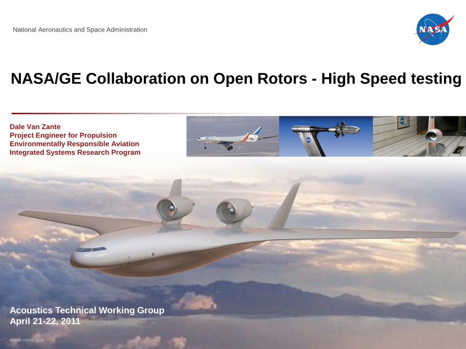
NASA/GE Collaboration on Open Rotors - High Speed Testing
A low-noise open rotor system is being tested in collaboration with General Electric and CFM International, a 50/50 joint company between Snecma and GE. Candidate technologies for lower noise will be investigated as well as installation effects such as pylon integration.Current test status for the 8x6 SWT high speed testing is presented as well as future scheduled testing which includes the FAA/CLEEN test entry. The tunnel blockage and propeller thrust calibration configurations are shown.
https://ntrs.nasa.gov/search.jsp?R=20110011394 2018-09-09T09:18:59+00:00Z
National Aeronautics and Space Administration
www.nasa.gov
NASA/GE Collaboration on Open Rotors - High Speed testing
Acoustics Technical Working GroupApril 21-22, 2011
Dale Van ZanteProject Engineer for PropulsionEnvironmentally Responsible AviationIntegrated Systems Research Program
Outline
3
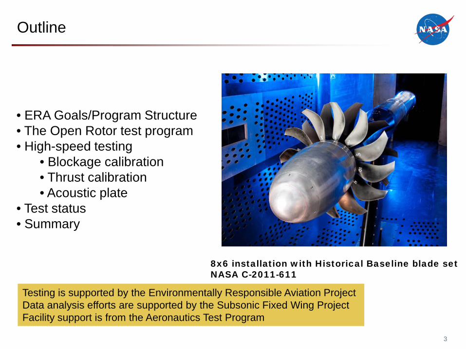
• ERA Goals/Program Structure• The Open Rotor test program• High-speed testing
• Blockage calibration• Thrust calibration• Acoustic plate
• Test status• Summary
Testing is supported by the Environmentally Responsible Aviation ProjectData analysis efforts are supported by the Subsonic Fixed Wing ProjectFacility support is from the Aeronautics Test Program
8x6 installation with Historical Baseline blade setNASA C-2011-611
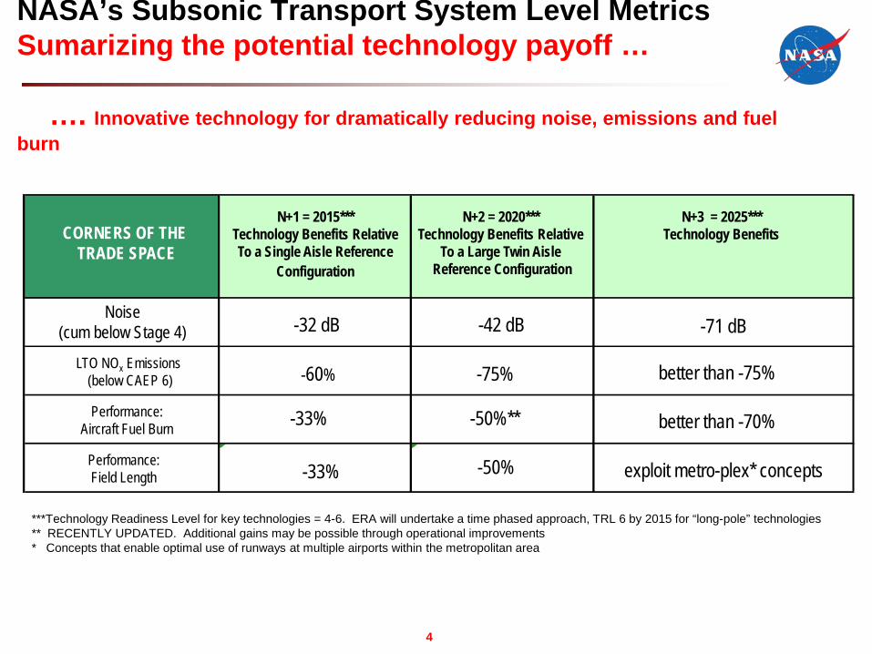
NASA’s Subsonic Transport System Level MetricsSumarizing the potential technology payoff …
…. Innovative technology for dramatically reducing noise, emissions and fuel burn
4
Noise(cum below Stage 4)
-60% -75% better than -75%
-33% -50%** better than -70%
-33% -50% exploit metro-plex* concepts
N+1 = 2015***Technology Benefits RelativeTo a Single Aisle Reference
Configuration
N+2 = 2020***Technology Benefits Relative
To a Large Twin AisleReference Configuration
N+3 = 2025***Technology Benefits
LTO NOx Emissions(below CAEP 6)
Performance:Aircraft Fuel Burn
Performance:Field Length
-32 dB -42 dB -71 dB
CORNERS OF THE TRADE SPACE
***Technology Readiness Level for key technologies = 4-6. ERA will undertake a time phased approach, TRL 6 by 2015 for “long-pole” technologies** RECENTLY UPDATED. Additional gains may be possible through operational improvements* Concepts that enable optimal use of runways at multiple airports within the metropolitan area
Business Team
• Deputy PM Business: Timothy Warner
• Lead Resource Analyst:• ARC Resource Analyst: Delphina Turner• DFRC Resource Analyst: Sarah Samples• GRC Resource Analyst: Lisa Ferenc
• Risk Manager: Jon Kilgore
• Schedule Analyst: Daniel Healey
• Configuration & Data Mgmt: Pamela Banks
• NRA Manager: Sherri Yokum
• AVC NRA Task Manager: Joseph Piotrowski
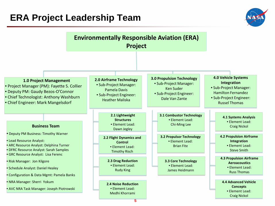
Environmentally Responsible Aviation (ERA) Project
1.0 Project Management• Project Manager (PM): Fayette S. Collier• Deputy PM: Gaudy Bezos-O’Connor• Chief Technologist: Anthony Washburn• Chief Engineer: Mark Mangelsdorf
2.0 Airframe Technology• Sub-Project Manager:
Pamela Davis• Sub-Project Engineer:
Heather Maliska
3.0 Propulsion Technology• Sub-Project Manager:
Ken Suder• Sub-Project Engineer:
Dale Van Zante
4.0 Vehicle Systems Integration
• Sub-Project Manager: Hamilton Fernandez
• Sub-Project Engineer: Russel Thomas
2.1 Lightweight Structures
• Element Lead: Dawn Jegley
2.2 Flight Dynamics and Control
• Element Lead: Timothy Risch
2.1 Lightweight Structures
Element Lead
2.4 Noise Reduction• Element Lead: Medhi Khorrami
3.3 Core Technology• Element Lead:
James Heidmann
3.2 Propulsor Technology• Element Lead:
Brian Fite
3.1 Combustor Technology• Element Lead:
Chi-Ming Lee
4.2 Propulsion Airframe Integration
• Element Lead: Steve Smith
4.3 Propulsion Airframe Aeroacoustics• Element Lead:
Russ Thomas
4.4 Advanced Vehicle Concepts
• Element Lead: Craig Nickol
4.1 Systems Analysis• Element Lead:
Craig Nickol
2.3 Drag Reduction• Element Lead:
Rudy King
ERA Project Leadership Team
5
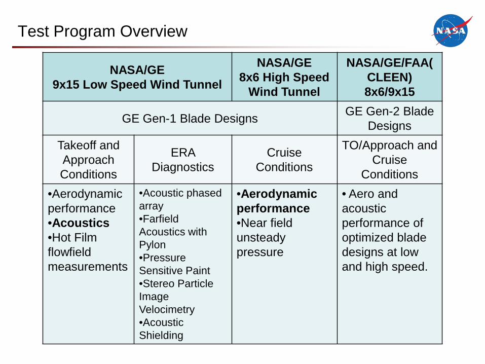
Test Program Overview
NASA/GE9x15 Low Speed Wind Tunnel
NASA/GE8x6 High Speed
Wind Tunnel
NASA/GE/FAA(CLEEN)8x6/9x15
GE Gen-1 Blade Designs GE Gen-2 Blade Designs
Takeoff and Approach Conditions
ERA Diagnostics
CruiseConditions
TO/Approach and Cruise
Conditions•Aerodynamic performance•Acoustics•Hot Film flowfieldmeasurements
•Acoustic phased array•FarfieldAcoustics with Pylon•PressureSensitive Paint•Stereo Particle Image Velocimetry•Acoustic Shielding
•Aerodynamic performance•Near field unsteady pressure
• Aero and acousticperformance of optimized blade designs at low and high speed.
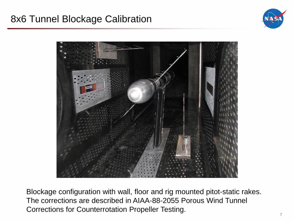
8x6 Tunnel Blockage Calibration
7
Blockage configuration with wall, floor and rig mounted pitot-static rakes.The corrections are described in AIAA-88-2055 Porous Wind Tunnel Corrections for Counterrotation Propeller Testing.

8x6 Tunnel Thrust Calibration
8
ORPR with Historical Baseline Blade Set
NASA C-2011-625
A static tube is used to determine Mach number through test section with propeller thrust.
• 3 rows of 30 statics • Floor or ceiling mount

Acoustic Plate Installation
9
ORPR with Historical Baseline Blade Set
NASA C-2011-620

NASA/GE Collaboration8x6 High Speed Wind Tunnel test
10NASA NAS3-24080, Task V Final Report
Objectives: Aerodynamic performance and near field unsteady pressure measurements at cruise Mach number.P(t) is processed to produce the cross-spectral matrix.Code by Cliff Brown, Don Braun, David Stephens.
There are 17 Kulite XCL-093 in an axial line down the center of the plate.(Note: the Kulite numbering is reversed for the current installation. No. 17 is at the forward end of the plate.)

Test Status
11
A instrumentation problem with the forward rotor force balance occurred on April 6.Testing is on hold until the issue can be resolved.
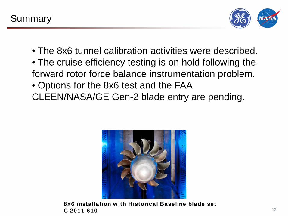
Summary
12
• The 8x6 tunnel calibration activities were described.• The cruise efficiency testing is on hold following the forward rotor force balance instrumentation problem.• Options for the 8x6 test and the FAA CLEEN/NASA/GE Gen-2 blade entry are pending.
8x6 installation with Historical Baseline blade set C-2011-610
Partners
Publications
14
Elliott, David M., “Initial Investigation of the Acoustics of a Counter Rotating Open Rotor Model With Historical Baseline Blades in a Low Speed Wind Tunnel,” to be presented at AIAA AeroacousticsConference, Portland, Oregon, June 2011.
Stephens, David and Envia, Edmane, “Acoustic Shielding for a Model Scale Counter-rotation Open Rotor,” to be presented at AIAA Aeroacoustics Conference, Portland, Oregon, June 2011.
Berton, Jeffery J., “Empennage Noise Shielding Benefits for an Open Rotor Transport,” to be presented at AIAA Aeroacoustics Conference, Portland, Oregon, June 2011.
Hendricks, Eric, “DEVELOPMENT OF AN OPEN ROTOR CYCLE MODEL IN NPSS USING A MULTI-DESIGN POINT APPROACH,” GT2011-46694, to be presented at Turbo Expo 2011, Vancouver, BC, June 2011.
Van Zante, Dale, Gazzaniga, John, Elliott, David, and Woodward, Richard, “An Open Rotor Test Case: F31/A31 Historical Baseline Blade Set,” to be presented at ISABE 2011, Gothenburg, Sweden. September 2011.