nasa’s magnetospheric multiscale (mms) mission · 1 nasa’s magnetospheric multiscale (mms)...
TRANSCRIPT

1
NASA’s Magnetospheric Multiscale (MMS) Mission
2015 University of North Dakota Space Studies Colloquium
Craig Tooley - MMS Project ManagerNASA Goddard Space Flight Center
https://ntrs.nasa.gov/search.jsp?R=20150018412 2018-07-13T12:50:05+00:00Z
April 20, 2015 MMS for UND Space Studies Colloquium 2
Today’s Presentation
Who your speaker is
The purpose of the MMS mission
The Spacecraft we built to execute the mission
How the development was executed
The launch and operation of the mission
Status of the mission now
Questions & discussion
Magnetospheric Multiscale (MMS) Mission
April 20, 2015 MMS for UND Space Studies Colloquium 3
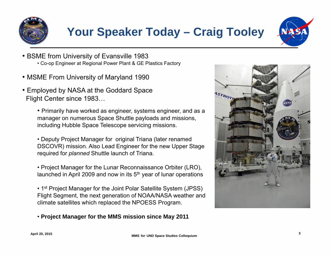
Your Speaker Today – Craig Tooley
• BSME from University of Evansville 1983• Co-op Engineer at Regional Power Plant & GE Plastics Factory
• MSME From University of Maryland 1990
• Employed by NASA at the Goddard Space Flight Center since 1983…
• Primarily have worked as engineer, systems engineer, and as a manager on numerous Space Shuttle payloads and missions, including Hubble Space Telescope servicing missions.
• Deputy Project Manager for original Triana (later renamed DSCOVR) mission. Also Lead Engineer for the new Upper Stage required for planned Shuttle launch of Triana.
• Project Manager for the Lunar Reconnaissance Orbiter (LRO), launched in April 2009 and now in its 5th year of lunar operations
• 1st Project Manager for the Joint Polar Satellite System (JPSS) Flight Segment, the next generation of NOAA/NASA weather and climate satellites which replaced the NPOESS Program.
• Project Manager for the MMS mission since May 2011
April 20, 2015 MMS for UND Space Studies Colloquium 4
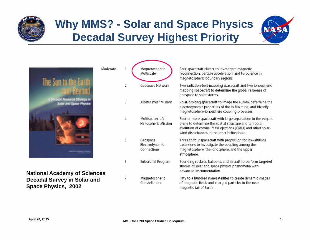
Why MMS? - Solar and Space PhysicsDecadal Survey Highest Priority
National Academy of SciencesDecadal Survey in Solar and Space Physics, 2002
April 20, 2015 MMS for UND Space Studies Colloquium 5
MMS Mission Overview
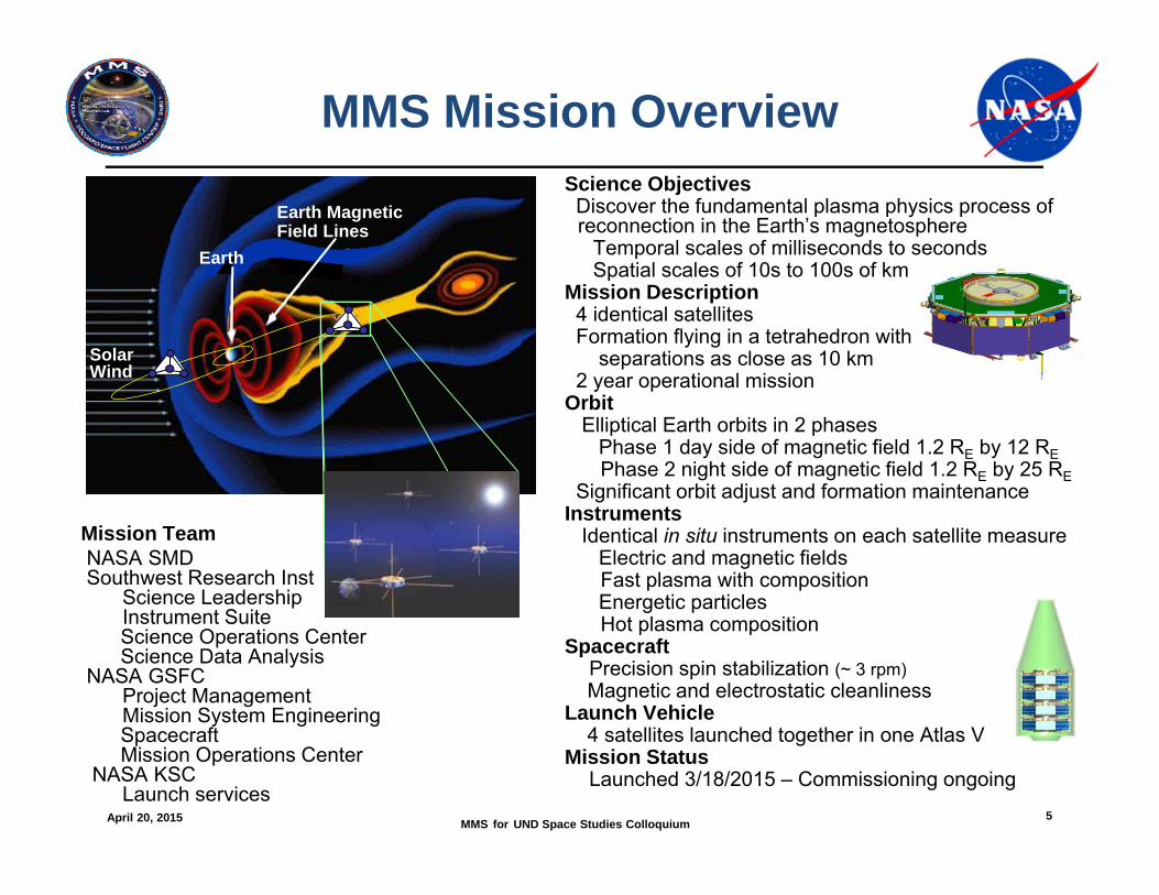
Mission TeamNASA SMDSouthwest Research Inst
Science Leadership Instrument SuiteScience Operations CenterScience Data Analysis
NASA GSFCProject ManagementMission System EngineeringSpacecraftMission Operations Center
NASA KSCLaunch services
Science ObjectivesDiscover the fundamental plasma physics process of reconnection in the Earth’s magnetosphere
Temporal scales of milliseconds to secondsSpatial scales of 10s to 100s of km
Mission Description4 identical satellitesFormation flying in a tetrahedron with
separations as close as 10 km2 year operational mission
OrbitElliptical Earth orbits in 2 phases
Phase 1 day side of magnetic field 1.2 RE by 12 REPhase 2 night side of magnetic field 1.2 RE by 25 RE
Significant orbit adjust and formation maintenance Instruments
Identical in situ instruments on each satellite measureElectric and magnetic fieldsFast plasma with compositionEnergetic particlesHot plasma composition
SpacecraftPrecision spin stabilization (~ 3 rpm)Magnetic and electrostatic cleanliness
Launch Vehicle4 satellites launched together in one Atlas V
Mission Status Launched 3/18/2015 – Commissioning ongoing
Earth
SolarWind
Earth MagneticField Lines
Earth
April 20, 2015 MMS for UND Space Studies Colloquium 6
NASA MMS Mission Trailer Video
April 20, 2015 MMS for UND Space Studies Colloquium 7
Universal Process of Magnetic Reconnection
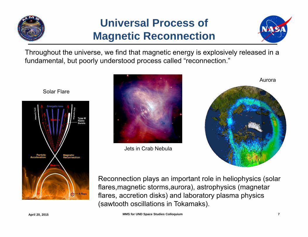
Throughout the universe, we find that magnetic energy is explosively released in a fundamental, but poorly understood process called “reconnection.”
Reconnection plays an important role in heliophysics (solar flares,magnetic storms,aurora), astrophysics (magnetar flares, accretion disks) and laboratory plasma physics (sawtooth oscillations in Tokamaks).
Jets in Crab Nebula
Solar Flare
Aurora
April 20, 2015 MMS for UND Space Studies Colloquium 8
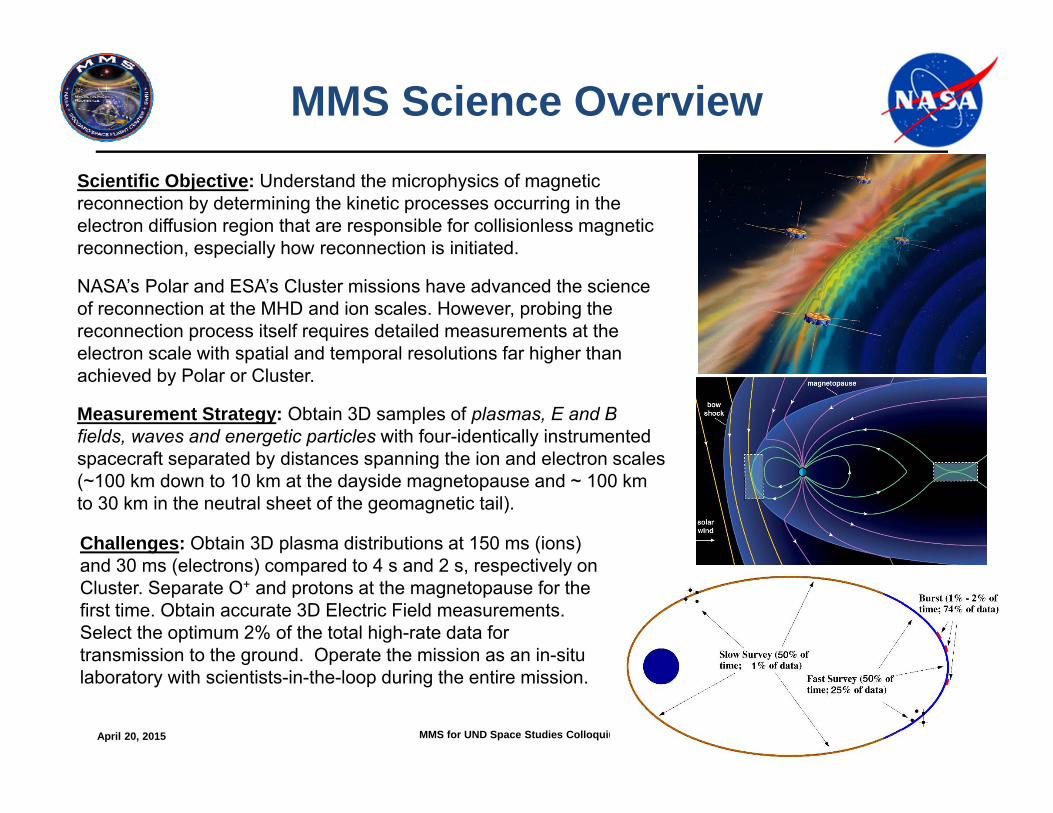
MMS Science OverviewScientific Objective: Understand the microphysics of magnetic reconnection by determining the kinetic processes occurring in the electron diffusion region that are responsible for collisionless magnetic reconnection, especially how reconnection is initiated.
NASA’s Polar and ESA’s Cluster missions have advanced the science of reconnection at the MHD and ion scales. However, probing the reconnection process itself requires detailed measurements at the electron scale with spatial and temporal resolutions far higher than achieved by Polar or Cluster.
Measurement Strategy: Obtain 3D samples of plasmas, E and B fields, waves and energetic particles with four-identically instrumented spacecraft separated by distances spanning the ion and electron scales (~100 km down to 10 km at the dayside magnetopause and ~ 100 km to 30 km in the neutral sheet of the geomagnetic tail).
Challenges: Obtain 3D plasma distributions at 150 ms (ions) and 30 ms (electrons) compared to 4 s and 2 s, respectively on Cluster. Separate O+ and protons at the magnetopause for the first time. Obtain accurate 3D Electric Field measurements. Select the optimum 2% of the total high-rate data for transmission to the ground. Operate the mission as an in-situ laboratory with scientists-in-the-loop during the entire mission.
April 20, 2015 MMS for UND Space Studies Colloquium 9
Where MMS Explores Magnetic Reconnection
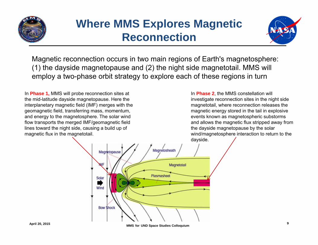
Magnetic reconnection occurs in two main regions of Earth's magnetosphere: (1) the dayside magnetopause and (2) the night side magnetotail. MMS will employ a two-phase orbit strategy to explore each of these regions in turn
In Phase 1, MMS will probe reconnection sites at the mid-latitude dayside magnetopause. Here the interplanetary magnetic field (IMF) merges with the geomagnetic field, transferring mass, momentum, and energy to the magnetosphere. The solar wind flow transports the merged IMF/geomagnetic field lines toward the night side, causing a build up of magnetic flux in the magnetotail.
In Phase 2, the MMS constellation will investigate reconnection sites in the night side magnetotail, where reconnection releases the magnetic energy stored in the tail in explosive events known as magnetospheric substorms and allows the magnetic flux stripped away from the dayside magnetopause by the solar wind/magnetosphere interaction to return to the dayside.
April 20, 2015 MMS for UND Space Studies Colloquium 10
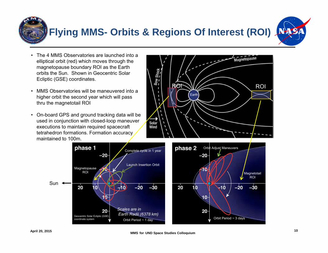
Flying MMS- Orbits & Regions Of Interest (ROI)
Scales are inEarth Radii (6378 km)
• The 4 MMS Observatories are launched into a elliptical orbit (red) which moves through the magnetopause boundary ROI as the Earth orbits the Sun. Shown in Geocentric Solar Ecliptic (GSE) coordinates.
• MMS Observatories will be maneuvered into a higher orbit the second year which will pass thru the magnetotail ROI
• On-board GPS and ground tracking data will be used in conjunction with closed-loop maneuver executions to maintain required spacecraft tetrahedron formations. Formation accuracy maintained to 100m.
ROIROIEarth
MagnetopauseROI Magnetotail
ROI
Launch Insertion Orbit
Orbit Adjust Maneuvers
Orbit Period ~ 1 day Orbit Period ~ 3 days
Complete cycle in 1 year
Geocentric Solar Ecliptic (GSE) coordinate system
Sun
April 20, 2015 MMS for UND Space Studies Colloquium 11
MMS Mission Simulation Video
April 20, 2015 MMS for UND Space Studies Colloquium 12
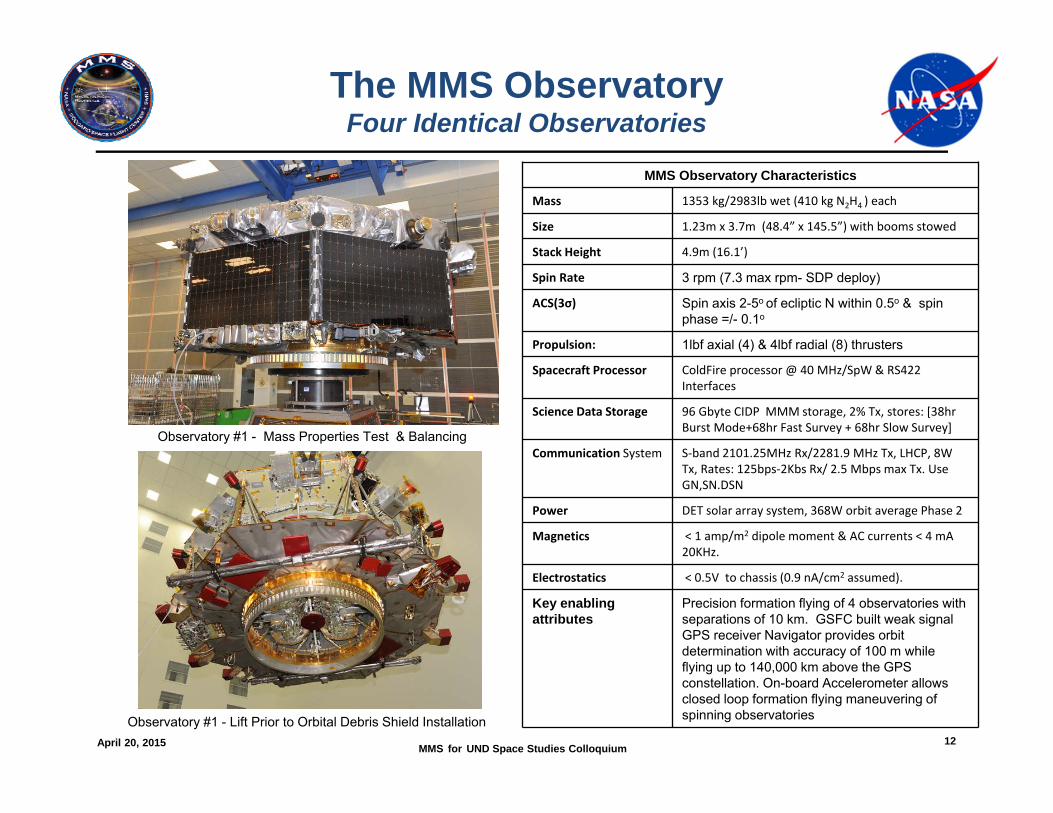
The MMS ObservatoryFour Identical Observatories
MMS Observatory Characteristics
Mass 1353 kg/2983lb wet (410 kg N2H4 ) each
Size 1.23m x 3.7m (48.4” x 145.5”) with booms stowed
Stack Height 4.9m (16.1’)
Spin Rate 3 rpm (7.3 max rpm- SDP deploy)
ACS(3σ) Spin axis 2-5o of ecliptic N within 0.5o & spin phase =/- 0.1o
Propulsion: 1lbf axial (4) & 4lbf radial (8) thrusters
Spacecraft Processor ColdFire processor @ 40 MHz/SpW & RS422 Interfaces
Science Data Storage 96 Gbyte CIDP MMM storage, 2% Tx, stores: [38hr Burst Mode+68hr Fast Survey + 68hr Slow Survey]
Communication System S‐band 2101.25MHz Rx/2281.9 MHz Tx, LHCP, 8W Tx, Rates: 125bps‐2Kbs Rx/ 2.5 Mbps max Tx. Use GN,SN.DSN
Power DET solar array system, 368W orbit average Phase 2
Magnetics < 1 amp/m2 dipole moment & AC currents < 4 mA 20KHz.
Electrostatics < 0.5V to chassis (0.9 nA/cm2 assumed).
Key enabling attributes
Precision formation flying of 4 observatories with separations of 10 km. GSFC built weak signal GPS receiver Navigator provides orbit determination with accuracy of 100 m while flying up to 140,000 km above the GPS constellation. On-board Accelerometer allows closed loop formation flying maneuvering of spinning observatories
Observatory #1 - Mass Properties Test & Balancing
Observatory #1 - Lift Prior to Orbital Debris Shield Installation
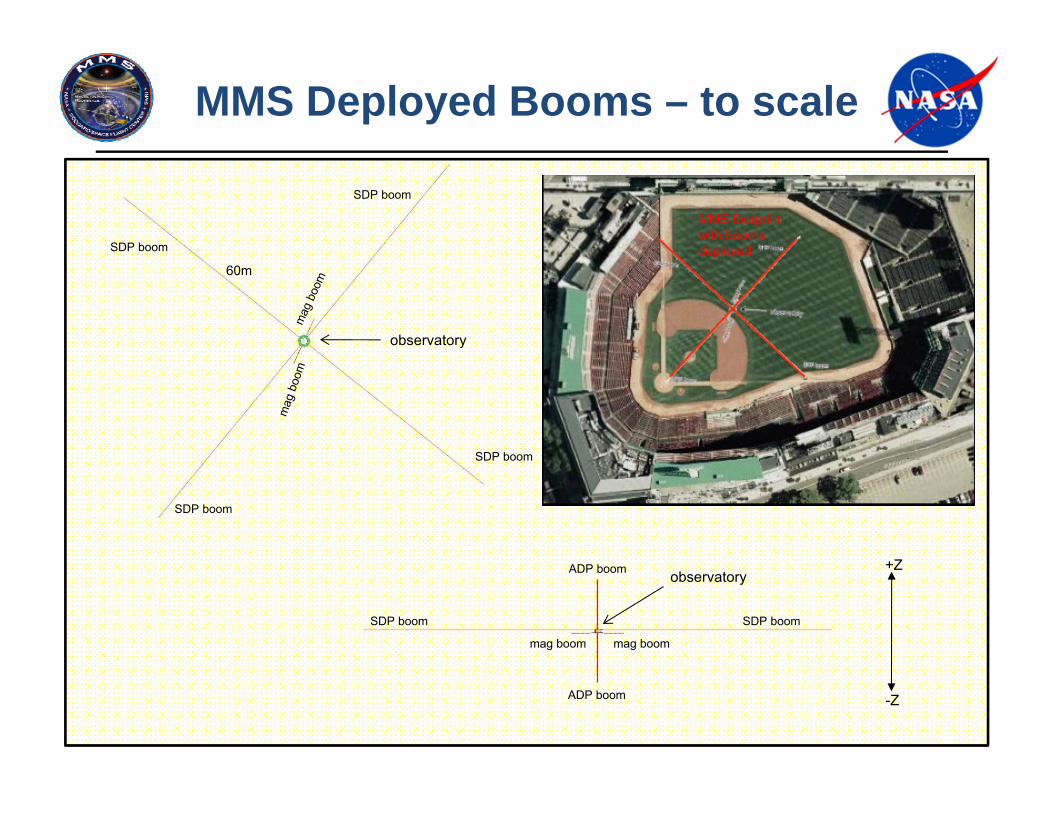
MMS Deployed Booms – to scale
SDP boom
SDP boom
SDP boom
SDP boom
SDP boomSDP boom
mag boommag boom
ADP boom
ADP boom
observatory
observatory+Z
-Z
MMS footprint with booms deployed
60m
April 20, 2015 MMS for UND Space Studies Colloquium 14
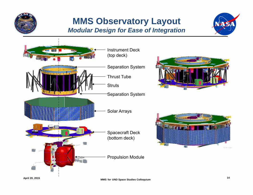
MMS Observatory LayoutModular Design for Ease of Integration
Instrument Deck(top deck)
Thrust Tube
Spacecraft Deck(bottom deck)
Propulsion Module
Struts
Separation System
Separation System
Solar Arrays

April 20, 2015 MMS for UND Space Studies Colloquium 15
MMS Science Instruments
MMS InstrumentsADP - Axial Double Probe/UNH-LASP (8)AFG - Analog Flux Gate Magnetometer/UNH-UCLA (4)ASPOC - Active Spacecraft Potential Control/IWF Austria (8)CEB - Central Electronics Box (Fields)/ UNH (4)CIDP - Central Instrument Data Processor/SwRI (4)DES - Dual Electron Spectrometer/Meisei Japan (16)DFG - Digital Flux Gate Magnetometer/UCLA/IWF Austria(4)DIS - Dual Ion Spectrometer/GSFC (16)EDI/GDU - Electron Drift Instrument/ GunDetector Unit/ UNH-IWF (8)EIS - Energetic Ion Spectrometer/APL (4)FEEPS - Fly’s Eye Energetic Particle Sensors/Aerospace (8)HPCA - Hot Plasma Composition Analyzer/SwRI (4)IDPU - Instrument Data Processing Unit (FPI)/GSFC (4)SCM - Search-Coil Magnetometer (mounted on boom)/UNH-LPP France (4)SDP - Spin-Plane Double Probe/UNH/KTH Sweden/LASP (16)
View looking up at inner side of an MMS Instrument Deck with Spacecraft Deck, Tanks, and solar arrays not shown
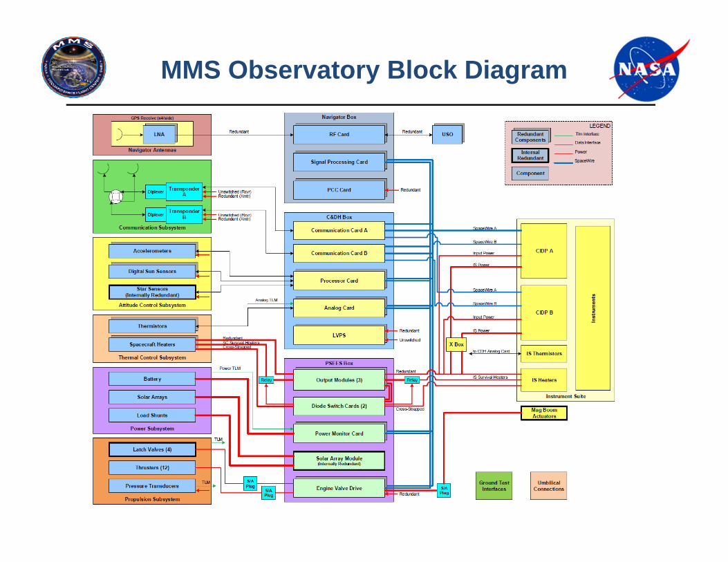
MMS Observatory Block Diagram
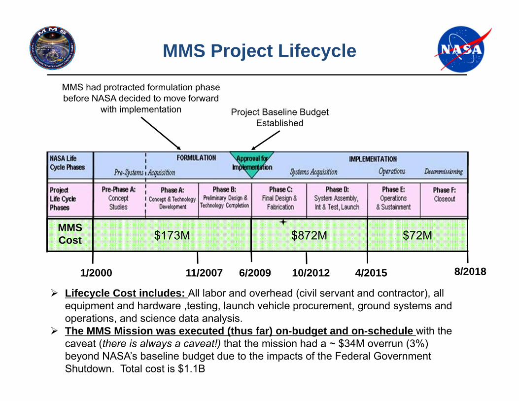
1/2000 11/2007 6/2009 10/2012 4/2015 8/2018
MMS Cost $173M $872M $72M
MMS Project Lifecycle
MMS had protracted formulation phase before NASA decided to move forward
with implementation Project Baseline Budget Established
Lifecycle Cost includes: All labor and overhead (civil servant and contractor), all equipment and hardware ,testing, launch vehicle procurement, ground systems and operations, and science data analysis.
The MMS Mission was executed (thus far) on-budget and on-schedule with the caveat (there is always a caveat!) that the mission had a ~ $34M overrun (3%) beyond NASA’s baseline budget due to the impacts of the Federal Government Shutdown. Total cost is $1.1B
April 20, 2015 MMS for UND Space Studies Colloquium 18
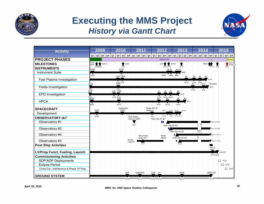
Executing the MMS ProjectHistory via Gantt Chart
2009 2010 2011 2012 2013 2014 2015Q1 Q2 Q3 Q4 Q1 Q2 Q3 Q4 Q1 Q2 Q3 Q4 Q1 Q2 Q3 Q4 Q1 Q2 Q3 Q4 Q1 Q2 Q3 Q4 Q1 Q2 Q3 Q4
Activity
PROJECT PHASESMILESTONESINSTRUMENTS Instrument Suite
Fast Plasma Investigation
Fields Investigation
EPD Investigation
HPCA
SPACECRAFT DevelopmentOBSERVATORY I&T Observatory #1
Observatory #2
Observatory #4
Observatory #3Post Ship Activities
LV/Prop Funct, Fueling, LaunchCommissioning Acticities SDP/ADP Deployments Eclipse Period Cross-Cal., Interference & Phase 1A Prep
GROUND SYSTEM
Phase B Phase C/D Phase E
5/09
PDR/NAR
6/09
KDP-C
8/10
CDR
8/12
SIR
10/12
KDP-D
6/13
PER
PSR11/14
PSR/ORR
3/15
Launch
9/15
StartPhase E
2/09
IPDR
7/10
ICDR
10/12
#1
12/12
#2
3/13
#3
5/13
#4
5/10
CDR
7/10
CDR
9/13
#4
1/14
#3
5/14
#18/14
#2
1/09
PDR
5/10
CDR
1/14
#3
7/14
#1,29/14#4 (EDI)
1/09
PDR
3/10
CDR
5/10
CDR
5/12
#1
9/12
#2
12/12
#34/13
#4
2/09
PDR
6/10
CDR
5/12
#1
10/12
#2
4/13
#48/13
#3
5/09
PDR Subsystem CDRs
1/12
Begin S/C #1Build-up
10/12
SC#1
12/12
SC #2
3/13
SC #3
5/13
SC #4
2/11
Risk Reduc.Deck to SwRI Start Obs #1 I&T
Ship 10/27-29
Start Obs #2 I&TShip 10/27-29
Start Obs #4 I&T Stack Vibe
Ship 11/12-14
ThrustTube #1
7/11
Struct Assy Qual Unit
StackModal
5/13
Start Obs #3 I&TShip 11/12-14
12/14
Nav re-install
3/15Launch
5/15
6/15
9/15
10/10
SRR
6/11
SDR/PDR
2/12
CDR
5/12
R1
6/13
MOR
11/14
ORR/FOR
April 20, 2015 MMS for UND Space Studies Colloquium 19
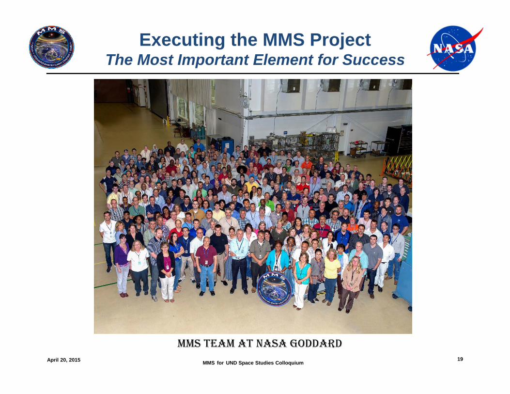
Executing the MMS ProjectThe Most Important Element for Success
MMS TEAM AT NASA GODDARD
April 20, 2015 MMS for UND Space Studies Colloquium 20
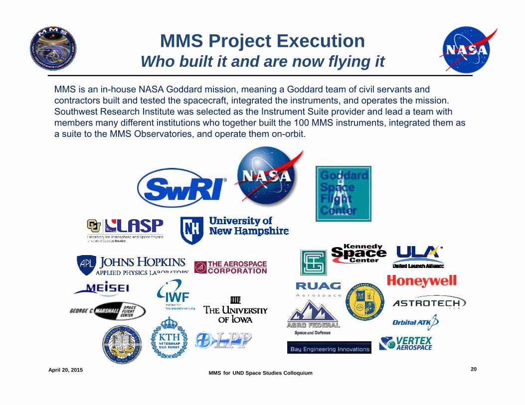
MMS Project ExecutionWho built it and are now flying it
MMS is an in-house NASA Goddard mission, meaning a Goddard team of civil servants and contractors built and tested the spacecraft, integrated the instruments, and operates the mission. Southwest Research Institute was selected as the Instrument Suite provider and lead a team with members many different institutions who together built the 100 MMS instruments, integrated them as a suite to the MMS Observatories, and operate them on-orbit.
April 20, 2015 MMS for UND Space Studies Colloquium 21
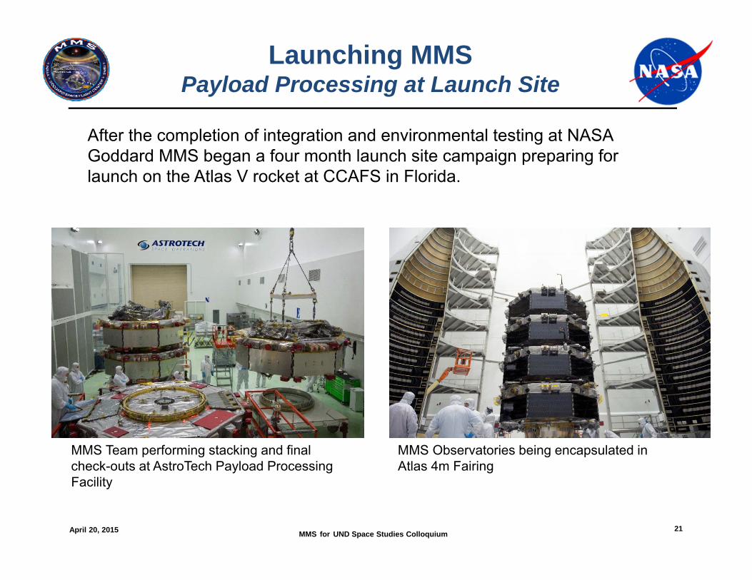
Launching MMSPayload Processing at Launch Site
After the completion of integration and environmental testing at NASA Goddard MMS began a four month launch site campaign preparing for launch on the Atlas V rocket at CCAFS in Florida.
MMS Team performing stacking and final check-outs at AstroTech Payload Processing Facility
MMS Observatories being encapsulated in Atlas 4m Fairing
April 20, 2015 MMS for UND Space Studies Colloquium 22
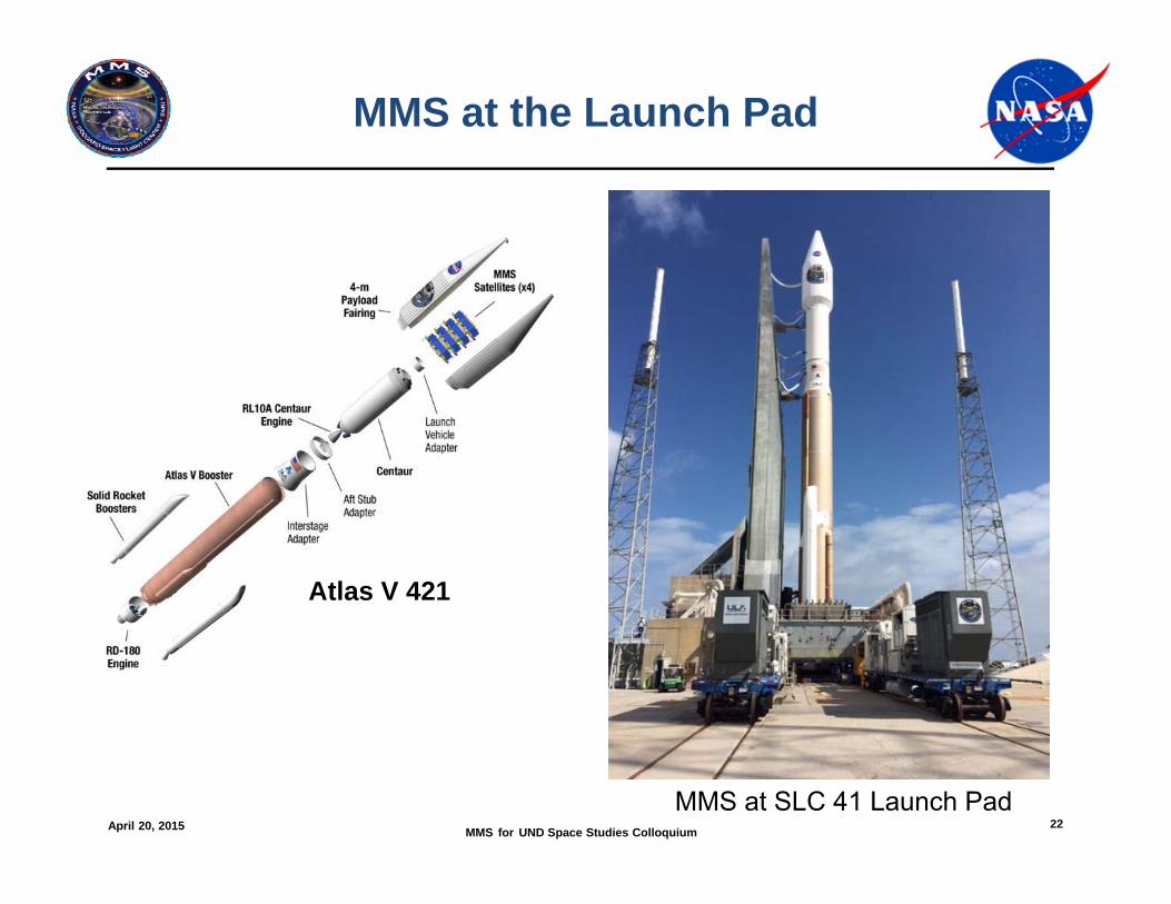
MMS at the Launch Pad
Atlas V 421
MMS at SLC 41 Launch Pad
April 20, 2015 MMS for UND Space Studies Colloquium 23
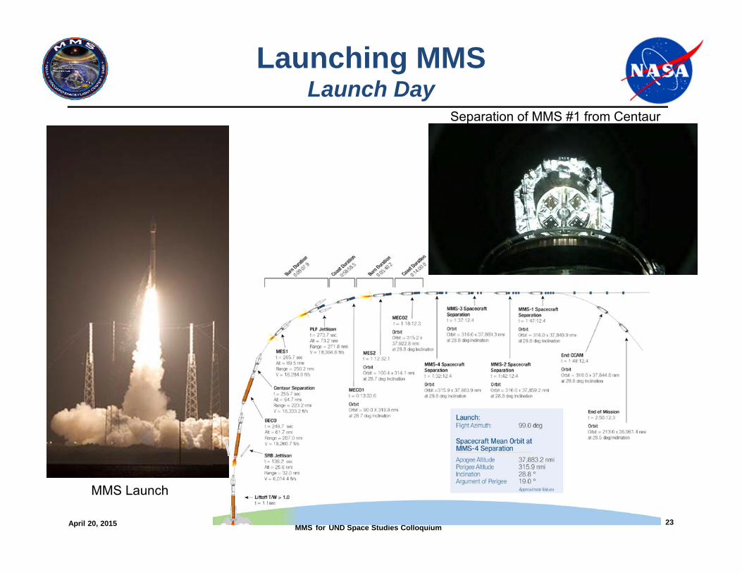
Launching MMSLaunch Day
MMS Launch
Separation of MMS #1 from Centaur
April 20, 2015 MMS for UND Space Studies Colloquium 24
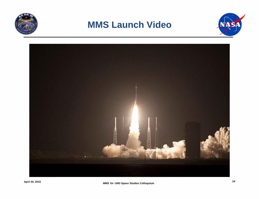
MMS Launch Video
April 20, 2015 MMS for UND Space Studies Colloquium 25
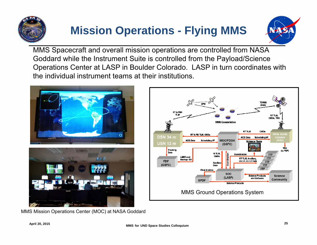
Mission Operations - Flying MMS
MMS Ground Operations System
MMS Mission Operations Center (MOC) at NASA Goddard
MMS Spacecraft and overall mission operations are controlled from NASA Goddard while the Instrument Suite is controlled from the Payload/Science Operations Center at LASP in Boulder Colorado. LASP in turn coordinates with the individual instrument teams at their institutions.
April 20, 2015 MMS for UND Space Studies Colloquium 26
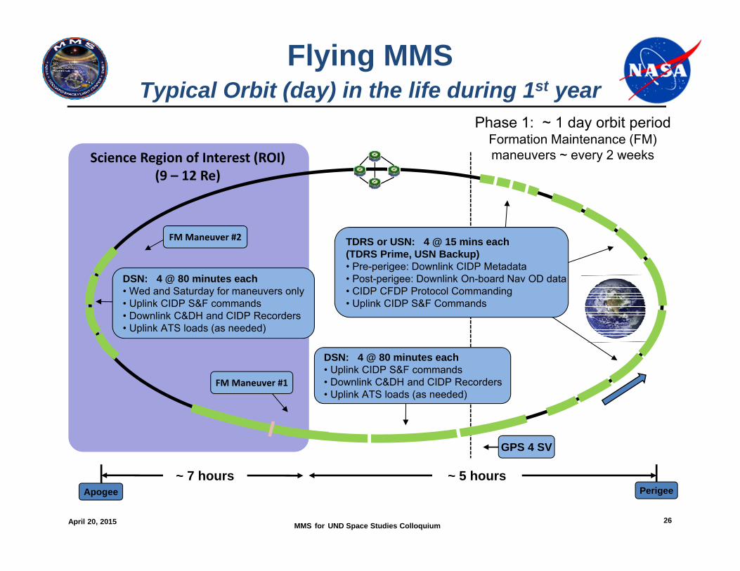
Flying MMSTypical Orbit (day) in the life during 1st year
Science Region of Interest (ROI)(9 – 12 Re)
Phase 1: ~ 1 day orbit periodFormation Maintenance (FM) maneuvers ~ every 2 weeks
FM Maneuver #2
GPS 4 SV
FM Maneuver #1
~ 5 hours~ 7 hours
DSN: 4 @ 80 minutes each• Wed and Saturday for maneuvers only• Uplink CIDP S&F commands • Downlink C&DH and CIDP Recorders• Uplink ATS loads (as needed)
DSN: 4 @ 80 minutes each• Uplink CIDP S&F commands • Downlink C&DH and CIDP Recorders• Uplink ATS loads (as needed)
TDRS or USN: 4 @ 15 mins each(TDRS Prime, USN Backup)• Pre-perigee: Downlink CIDP Metadata• Post-perigee: Downlink On-board Nav OD data• CIDP CFDP Protocol Commanding• Uplink CIDP S&F Commands
Apogee Perigee
April 20, 2015 MMS for UND Space Studies Colloquium 27
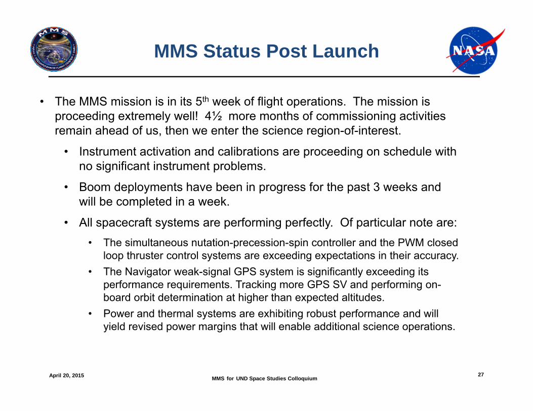
MMS Status Post Launch
• The MMS mission is in its 5th week of flight operations. The mission is proceeding extremely well! 4½ more months of commissioning activities remain ahead of us, then we enter the science region-of-interest.
• Instrument activation and calibrations are proceeding on schedule with no significant instrument problems.
• Boom deployments have been in progress for the past 3 weeks and will be completed in a week.
• All spacecraft systems are performing perfectly. Of particular note are:• The simultaneous nutation-precession-spin controller and the PWM closed
loop thruster control systems are exceeding expectations in their accuracy.• The Navigator weak-signal GPS system is significantly exceeding its
performance requirements. Tracking more GPS SV and performing on-board orbit determination at higher than expected altitudes.
• Power and thermal systems are exhibiting robust performance and will yield revised power margins that will enable additional science operations.
April 20, 2015 MMS for UND Space Studies Colloquium 28
Links for Additional MMS Information & Media Resources
http://mms.gsfc.nasa.gov/images_multimedia.htmlhttp://www.nasa.gov/mission_pages/mms/multimedia/index.html#.VQhRNmNTf5whttps://www.flickr.com/photos/nasakennedy/sets/72157649836241016/with/16616462548/http://www.ulalaunch.com/file-library.aspx
NASA Goddard MMS Website: http://mms.gsfc.nasa.govNASA HQ MMS Website: http://www.nasa.gov/mission_pages/mmsMMS Facebook: https://www.facebook.com/MagMultiScaleSouthwest Research Institute MMS Website: http://mms.space.swri.eduUniversity of New Hampshire MMS Website: http://mms-fields.unh.eduMagnetic Reconnection Physics Forum: http://heliogeophysics.ning.com/
MMS Resources for Photos, Videos, & Animations
April 20, 2015 MMS for UND Space Studies Colloquium 29
Supplemental Information
April 20, 2015 MMS for UND Space Studies Colloquium 30
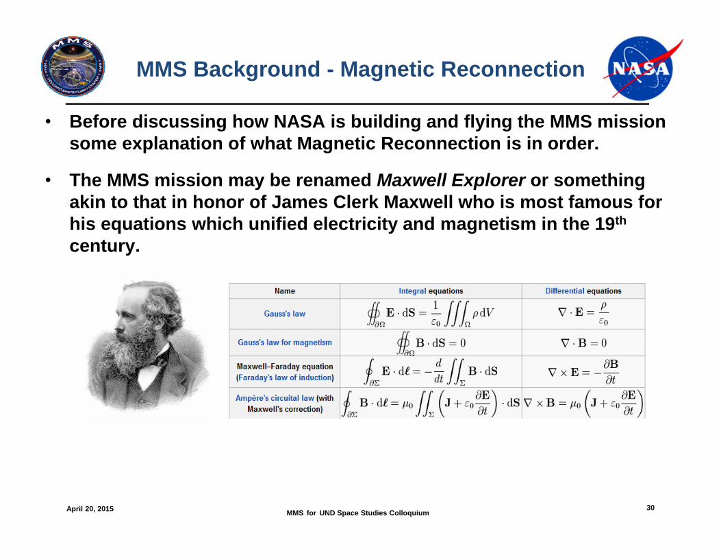
MMS Background - Magnetic Reconnection
• Before discussing how NASA is building and flying the MMS mission some explanation of what Magnetic Reconnection is in order.
• The MMS mission may be renamed Maxwell Explorer or something akin to that in honor of James Clerk Maxwell who is most famous for his equations which unified electricity and magnetism in the 19th
century.
April 20, 2015 MMS for UND Space Studies Colloquium 31
MMS Background- The Magnetosphere
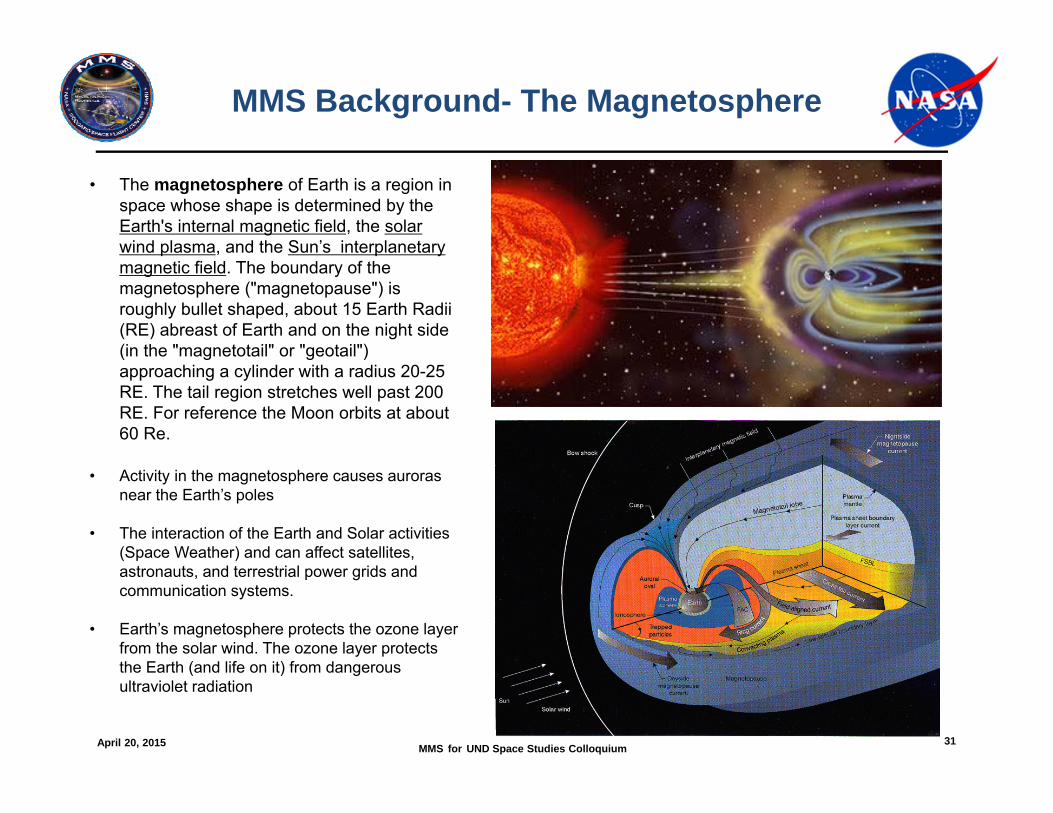
• The magnetosphere of Earth is a region in space whose shape is determined by the Earth's internal magnetic field, the solar wind plasma, and the Sun’s interplanetary magnetic field. The boundary of the magnetosphere ("magnetopause") is roughly bullet shaped, about 15 Earth Radii (RE) abreast of Earth and on the night side (in the "magnetotail" or "geotail") approaching a cylinder with a radius 20-25 RE. The tail region stretches well past 200 RE. For reference the Moon orbits at about 60 Re.
• Activity in the magnetosphere causes auroras near the Earth’s poles
• The interaction of the Earth and Solar activities (Space Weather) and can affect satellites, astronauts, and terrestrial power grids and communication systems.
• Earth’s magnetosphere protects the ozone layer from the solar wind. The ozone layer protects the Earth (and life on it) from dangerous ultraviolet radiation
April 20, 2015 MMS for UND Space Studies Colloquium 32
Magnetospheric Multiscale Mission Objective
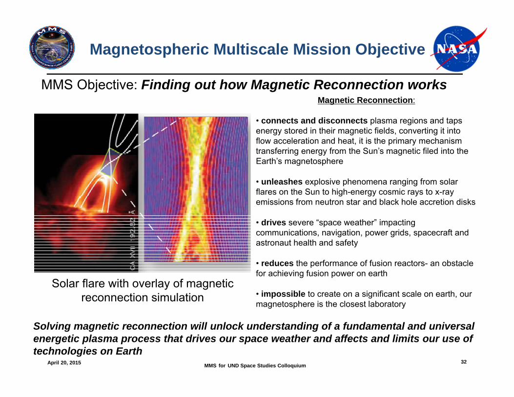
Solving magnetic reconnection will unlock understanding of a fundamental and universal energetic plasma process that drives our space weather and affects and limits our use of technologies on Earth
Magnetic Reconnection:
• connects and disconnects plasma regions and taps energy stored in their magnetic fields, converting it into flow acceleration and heat, it is the primary mechanism transferring energy from the Sun’s magnetic filed into the Earth’s magnetosphere
• unleashes explosive phenomena ranging from solar flares on the Sun to high-energy cosmic rays to x-ray emissions from neutron star and black hole accretion disks
• drives severe “space weather” impacting communications, navigation, power grids, spacecraft and astronaut health and safety
• reduces the performance of fusion reactors- an obstacle for achieving fusion power on earth
• impossible to create on a significant scale on earth, our magnetosphere is the closest laboratory
MMS Objective: Finding out how Magnetic Reconnection works
Solar flare with overlay of magnetic reconnection simulation
April 20, 2015 MMS for UND Space Studies Colloquium 33
What is Magnetic Reconnection?
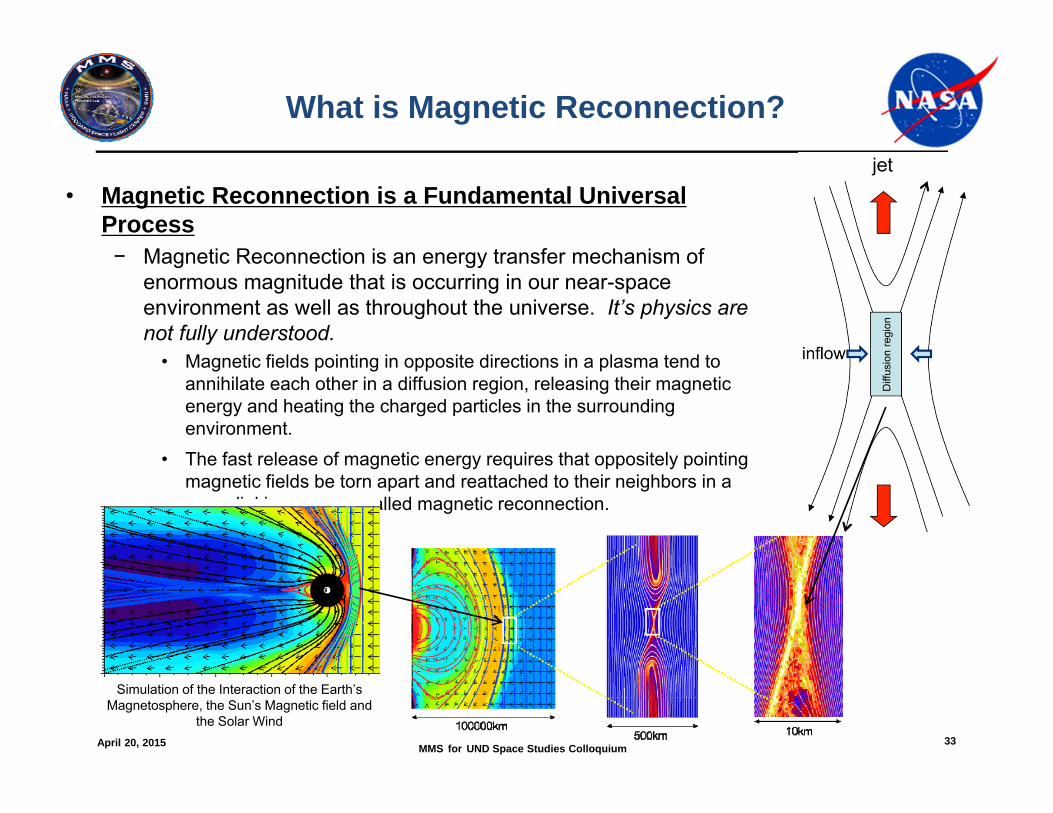
• Magnetic Reconnection is a Fundamental Universal Process− Magnetic Reconnection is an energy transfer mechanism of
enormous magnitude that is occurring in our near-space environment as well as throughout the universe. It’s physics are not fully understood.
• Magnetic fields pointing in opposite directions in a plasma tend to annihilate each other in a diffusion region, releasing their magnetic energy and heating the charged particles in the surrounding environment.
• The fast release of magnetic energy requires that oppositely pointing magnetic fields be torn apart and reattached to their neighbors in a cross-linking process called magnetic reconnection.
Simulation of the Interaction of the Earth’s Magnetosphere, the Sun’s Magnetic field and
the Solar Wind
April 20, 2015 MMS for UND Space Studies Colloquium 34
Understanding Magnetic Reconnection & what MMS needs to measure
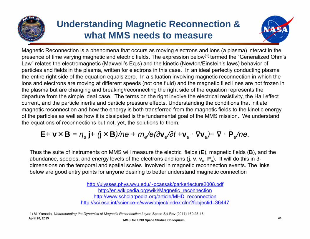
E+ v×B = ηs j+ (j×B)/ne + me/e(∂ve/∂t +ve · ve)− · Pe/ne.
Magnetic Reconnection is a phenomena that occurs as moving electrons and ions (a plasma) interact in the presence of time varying magnetic and electric fields. The expression below(1) termed the “Generalized Ohm’s Law” relates the electromagnetic (Maxwell’s Eq.s) and the kinetic (Newton/Einstein’s laws) behavior of particles and fields in the plasma, written for electrons in this case. In an ideal perfectly conducting plasma the entire right side of the equation equals zero. In a situation involving magnetic reconnection in which the ions and electrons are moving at different speeds (not one fluid) and the magnetic filed lines are not frozen in the plasma but are changing and breaking/reconnecting the right side of the equation represents the departure from the simple ideal case. The terms on the right involve the electrical resistivity, the Hall effect current, and the particle inertia and particle pressure effects. Understanding the conditions that initiate magnetic reconnection and how the energy is both transferred from the magnetic fields to the kinetic energy of the particles as well as how it is dissipated is the fundamental goal of the MMS mission. We understand the equations of reconnections but not, yet, the solutions to them.
Thus the suite of instruments on MMS will measure the electric fields (E), magnetic fields (B), and the abundance, species, and energy levels of the electrons and ions (j, v, ve, Pe). It will do this in 3-dimensions on the temporal and spatial scales involved in magnetic reconnection events. The links below are good entry points for anyone desiring to better understand magnetic connection
http://ulysses.phys.wvu.edu/~pcassak/parkerlecture2008.pdfhttp://en.wikipedia.org/wiki/Magnetic_reconnection
http://www.scholarpedia.org/article/MHD_reconnectionhttp://sci.esa.int/science-e/www/object/index.cfm?fobjectid=36447
1) M. Yamada, Understanding the Dynamics of Magnetic Reconnection Layer, Space Sci Rev (2011) 160:25-43
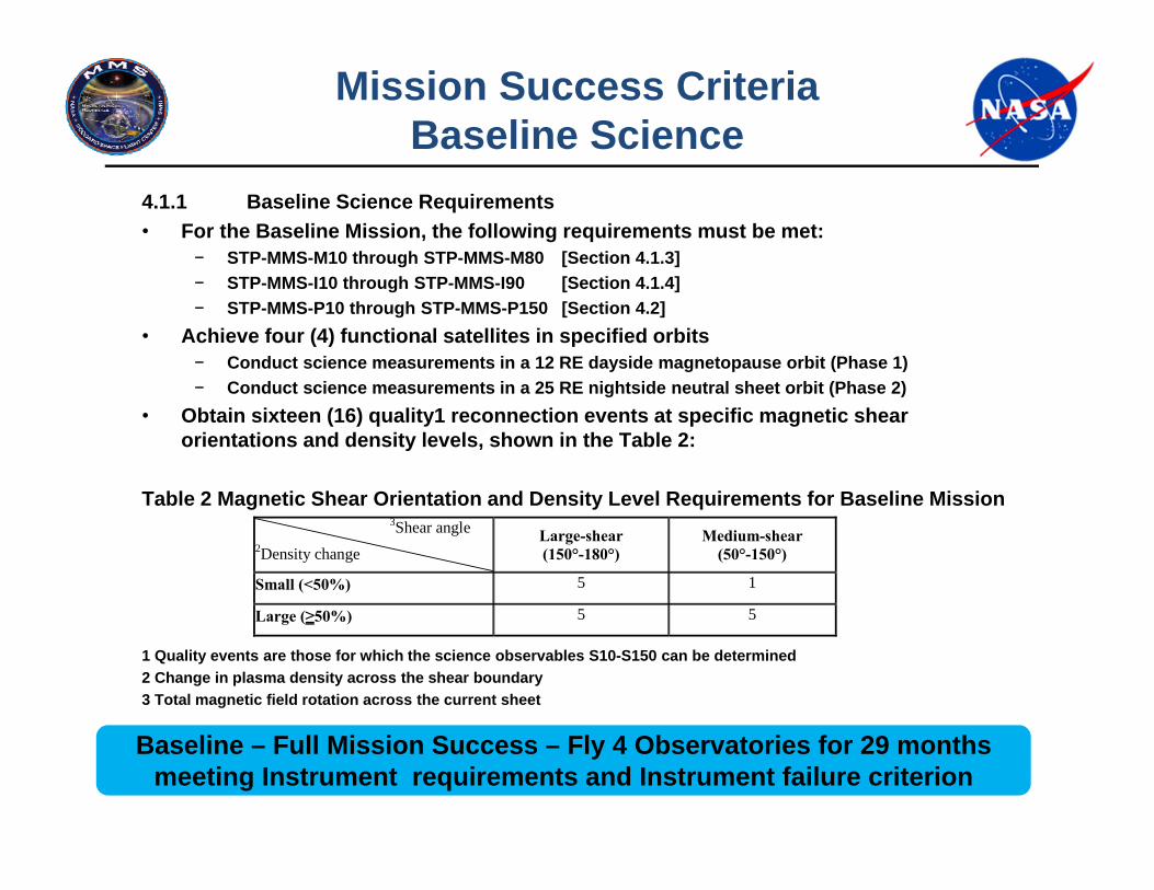
4.1.1 Baseline Science Requirements• For the Baseline Mission, the following requirements must be met:
− STP-MMS-M10 through STP-MMS-M80 [Section 4.1.3]− STP-MMS-I10 through STP-MMS-I90 [Section 4.1.4]− STP-MMS-P10 through STP-MMS-P150 [Section 4.2]
• Achieve four (4) functional satellites in specified orbits− Conduct science measurements in a 12 RE dayside magnetopause orbit (Phase 1)− Conduct science measurements in a 25 RE nightside neutral sheet orbit (Phase 2)
• Obtain sixteen (16) quality1 reconnection events at specific magnetic shear orientations and density levels, shown in the Table 2:
Table 2 Magnetic Shear Orientation and Density Level Requirements for Baseline Mission
1 Quality events are those for which the science observables S10-S150 can be determined2 Change in plasma density across the shear boundary3 Total magnetic field rotation across the current sheet
Baseline – Full Mission Success – Fly 4 Observatories for 29 months meeting Instrument requirements and Instrument failure criterion
Mission Success CriteriaBaseline Science
3Shear angle 2Density change
Large-shear (150°-180°)
Medium-shear (50°-150°)
Small (<50%) 5 1
Large (≥50%) 5 5
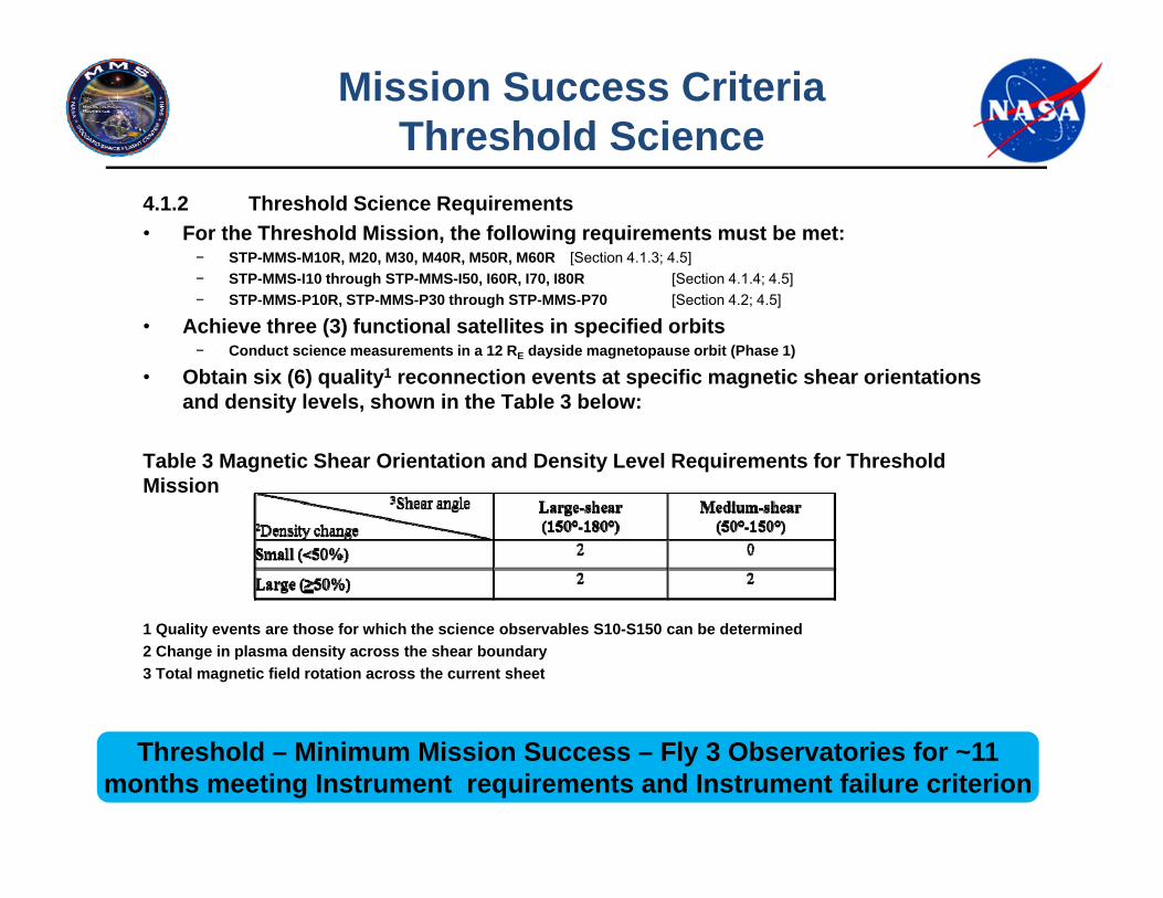
4.1.2 Threshold Science Requirements• For the Threshold Mission, the following requirements must be met:
− STP-MMS-M10R, M20, M30, M40R, M50R, M60R [Section 4.1.3; 4.5]− STP-MMS-I10 through STP-MMS-I50, I60R, I70, I80R [Section 4.1.4; 4.5]− STP-MMS-P10R, STP-MMS-P30 through STP-MMS-P70 [Section 4.2; 4.5]
• Achieve three (3) functional satellites in specified orbits− Conduct science measurements in a 12 RE dayside magnetopause orbit (Phase 1)
• Obtain six (6) quality1 reconnection events at specific magnetic shear orientations and density levels, shown in the Table 3 below:
Table 3 Magnetic Shear Orientation and Density Level Requirements for Threshold Mission
1 Quality events are those for which the science observables S10-S150 can be determined2 Change in plasma density across the shear boundary3 Total magnetic field rotation across the current sheet
Threshold – Minimum Mission Success – Fly 3 Observatories for ~11 months meeting Instrument requirements and Instrument failure criterion
Mission Success CriteriaThreshold Science
April 20, 2015 MMS for UND Space Studies Colloquium 37
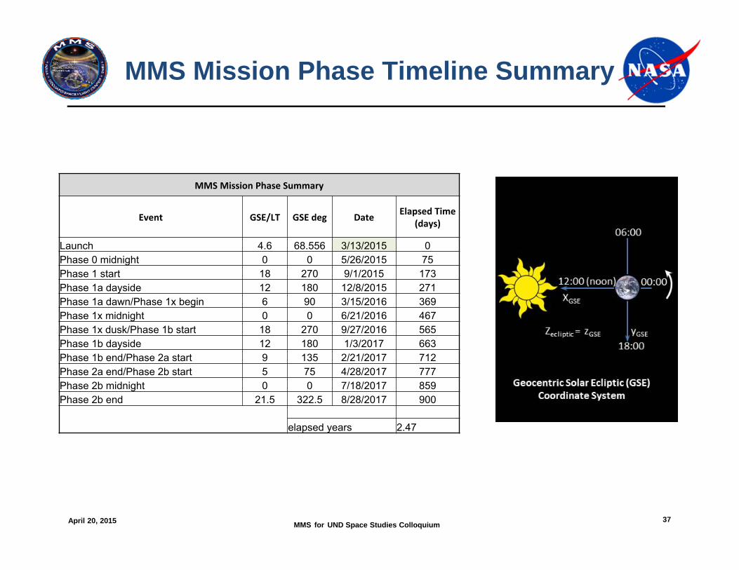
MMS Mission Phase Timeline Summary
MMS Mission Phase Summary
Event GSE/LT GSE deg Date Elapsed Time (days)
Launch 4.6 68.556 3/13/2015 0Phase 0 midnight 0 0 5/26/2015 75Phase 1 start 18 270 9/1/2015 173Phase 1a dayside 12 180 12/8/2015 271Phase 1a dawn/Phase 1x begin 6 90 3/15/2016 369Phase 1x midnight 0 0 6/21/2016 467Phase 1x dusk/Phase 1b start 18 270 9/27/2016 565Phase 1b dayside 12 180 1/3/2017 663Phase 1b end/Phase 2a start 9 135 2/21/2017 712Phase 2a end/Phase 2b start 5 75 4/28/2017 777Phase 2b midnight 0 0 7/18/2017 859Phase 2b end 21.5 322.5 8/28/2017 900
elapsed years 2.47
April 20, 2015 MMS for UND Space Studies Colloquium 38
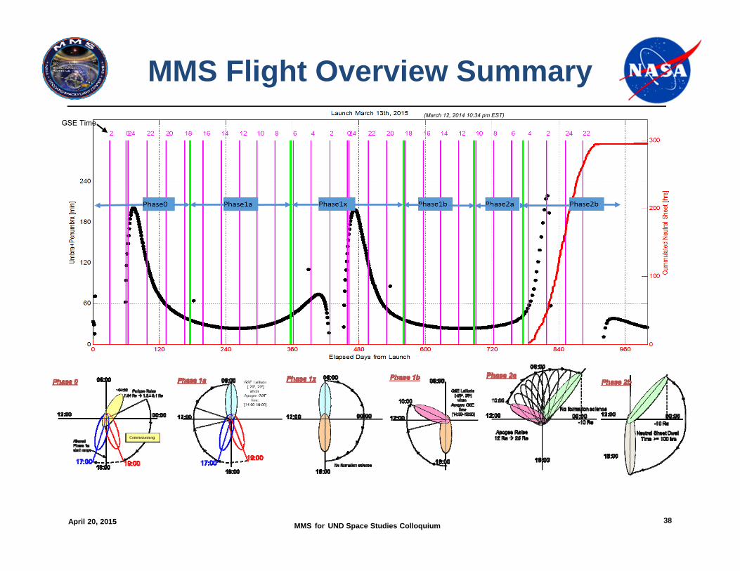
MMS Flight Overview Summary(March 12, 2014 10:34 pm EST)
GSE Time
April 20, 2015 MMS for UND Space Studies Colloquium 39
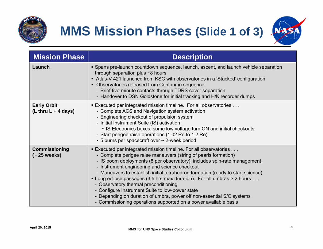
MMS Mission Phases (Slide 1 of 3)
Mission Phase DescriptionLaunch Spans pre-launch countdown sequence, launch, ascent, and launch vehicle separation
through separation plus ~8 hours Atlas-V 421 launched from KSC with observatories in a ‘Stacked’ configuration Observatories released from Centaur in sequence
- Brief five-minute contacts through TDRS cover separation- Handover to DSN Goldstone for initial tracking and H/K recorder dumps
Early Orbit(L thru L + 4 days)
Executed per integrated mission timeline. For all observatories . . .- Complete ACS and Navigation system activation- Engineering checkout of propulsion system- Initial Instrument Suite (IS) activation
• IS Electronics boxes, some low voltage turn ON and initial checkouts- Start perigee raise operations (1.02 Re to 1.2 Re)• 5 burns per spacecraft over ~ 2-week period
Commissioning(~ 25 weeks)
Executed per integrated mission timeline. For all observatories . . .- Complete perigee raise maneuvers (string of pearls formation)- IS boom deployments (8 per observatory); includes spin-rate management- Instrument engineering and science checkout- Maneuvers to establish initial tetrahedron formation (ready to start science)
Long eclipse passages (3.5 hrs max duration). For all umbras > 2 hours . . .- Observatory thermal preconditioning- Configure Instrument Suite to low-power state- Depending on duration of umbra, power off non-essential S/C systems- Commissioning operations supported on a power available basis
April 20, 2015 MMS for UND Space Studies Colloquium 40
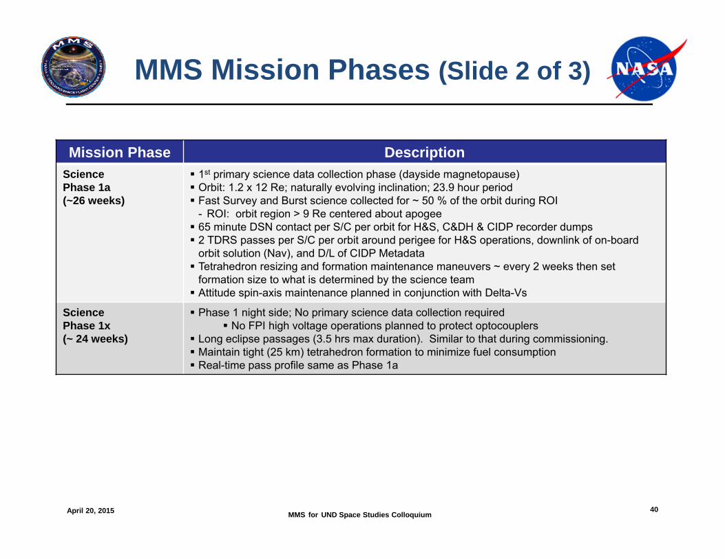
MMS Mission Phases (Slide 2 of 3)
Mission Phase DescriptionSciencePhase 1a(~26 weeks)
1st primary science data collection phase (dayside magnetopause) Orbit: 1.2 x 12 Re; naturally evolving inclination; 23.9 hour period Fast Survey and Burst science collected for ~ 50 % of the orbit during ROI
- ROI: orbit region > 9 Re centered about apogee 65 minute DSN contact per S/C per orbit for H&S, C&DH & CIDP recorder dumps 2 TDRS passes per S/C per orbit around perigee for H&S operations, downlink of on-board
orbit solution (Nav), and D/L of CIDP Metadata Tetrahedron resizing and formation maintenance maneuvers ~ every 2 weeks then set
formation size to what is determined by the science team Attitude spin-axis maintenance planned in conjunction with Delta-Vs
SciencePhase 1x(~ 24 weeks)
Phase 1 night side; No primary science data collection required No FPI high voltage operations planned to protect optocouplers
Long eclipse passages (3.5 hrs max duration). Similar to that during commissioning. Maintain tight (25 km) tetrahedron formation to minimize fuel consumption Real-time pass profile same as Phase 1a
April 20, 2015 MMS for UND Space Studies Colloquium 41
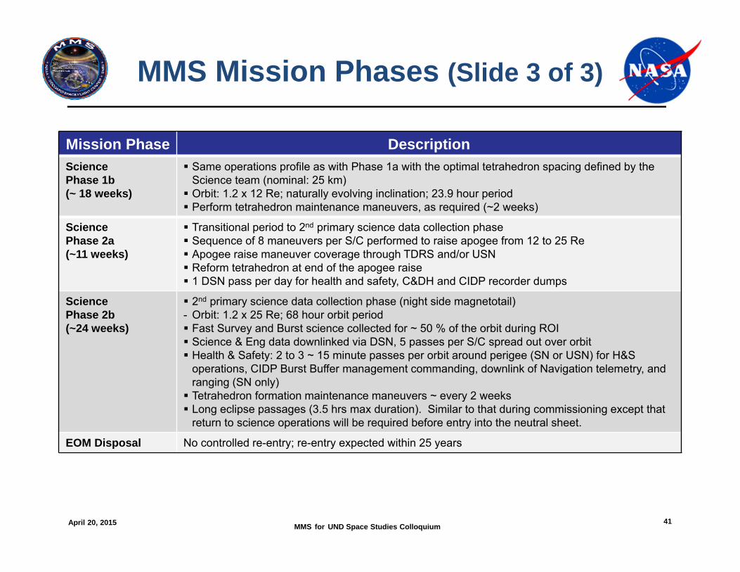
MMS Mission Phases (Slide 3 of 3)
Mission Phase DescriptionSciencePhase 1b(~ 18 weeks)
Same operations profile as with Phase 1a with the optimal tetrahedron spacing defined by the Science team (nominal: 25 km) Orbit: 1.2 x 12 Re; naturally evolving inclination; 23.9 hour period Perform tetrahedron maintenance maneuvers, as required (~2 weeks)
SciencePhase 2a(~11 weeks)
Transitional period to 2nd primary science data collection phase Sequence of 8 maneuvers per S/C performed to raise apogee from 12 to 25 Re Apogee raise maneuver coverage through TDRS and/or USN Reform tetrahedron at end of the apogee raise 1 DSN pass per day for health and safety, C&DH and CIDP recorder dumps
SciencePhase 2b(~24 weeks)
2nd primary science data collection phase (night side magnetotail)- Orbit: 1.2 x 25 Re; 68 hour orbit period Fast Survey and Burst science collected for ~ 50 % of the orbit during ROI Science & Eng data downlinked via DSN, 5 passes per S/C spread out over orbit Health & Safety: 2 to 3 ~ 15 minute passes per orbit around perigee (SN or USN) for H&S
operations, CIDP Burst Buffer management commanding, downlink of Navigation telemetry, and ranging (SN only) Tetrahedron formation maintenance maneuvers ~ every 2 weeks Long eclipse passages (3.5 hrs max duration). Similar to that during commissioning except that
return to science operations will be required before entry into the neutral sheet.
EOM Disposal No controlled re-entry; re-entry expected within 25 years
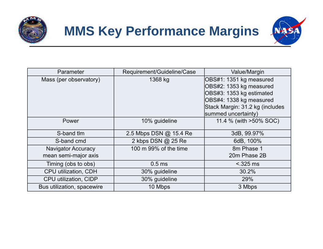
MMS Key Performance Margins
Parameter Requirement/Guideline/Case Value/MarginMass (per observatory) 1368 kg OBS#1: 1351 kg measured
OBS#2: 1353 kg measuredOBS#3: 1353 kg estimatedOBS#4: 1338 kg measuredStack Margin: 31.2 kg (includes summed uncertainty)
Power 10% guideline 11.4 % (with >50% SOC)
S-band tlm 2.5 Mbps DSN @ 15.4 Re 3dB, 99.97%S-band cmd 2 kbps DSN @ 25 Re 6dB, 100%
Navigator Accuracymean semi-major axis
100 m 99% of the time 8m Phase 120m Phase 2B
Timing (obs to obs) 0.5 ms <.325 msCPU utilization, CDH 30% guideline 30.2%CPU utilization, CIDP 30% guideline 29%
Bus utilization, spacewire 10 Mbps 3 Mbps
April 20, 2015 MMS for UND Space Studies Colloquium 43
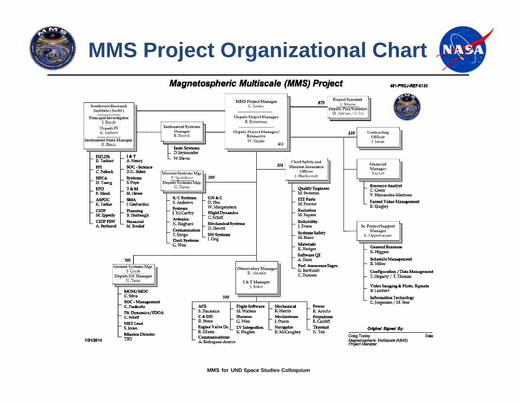
MMS Project Organizational Chart