nasgro k solutions · recent developments and challenges implementing . new and improved stress...
TRANSCRIPT

Recent Developments and Challenges Implementing New and Improved Stress Intensity Factor (K) Solutions
in NASGRO® for Damage Tolerance Analyses
Joseph W. Cardinal,1 R. Craig McClung,1 Yi-Der Lee,1 Yajun Guo,2 and Joachim M. Beek3
1Southwest Research Institute, San Antonio, Texas, USA 2Jacobs ESCG, Houston, Texas, USA
3NASA Johnson Space Center, Houston, Texas, USA
Abstract: Fatigue crack growth analysis software has been available to damage tolerance analysts for many years in either commercial products or via proprietary in-house codes. The NASGRO software has been publicly available since the mid-80s (known as NASA/FLAGRO up to 1999) and since 2000 has been sustained and further developed by a collaborative effort between Southwest Research Institute® (SwRI®), the NASA Johnson Space Center (JSC), and the members of the NASGRO Industrial Consortium. Since the stress intensity factor (K) is the foundation of fracture mechanics and damage tolerance analysis of aircraft structures, a significant focus of development efforts in the past fifteen years has been geared towards enhancing legacy K solutions and developing new and efficient numerical K solutions that can handle the complicated stress gradients computed by today’s analysts using detailed finite element models of fatigue critical locations. This paper provides an overview of K solutions that have been recently implemented or improved for the analysis of geometries such as two unequal through cracks at a hole and two unequal corner cracks at a hole, as well as state-of-the-art weight function models capable of computing K in the presence of univariant and/or bivariant stress gradients and complicated residual stress distributions. Some historical background is provided to review how common K solutions have evolved over the years, including selective examples from the literature and from new research. Challenges and progress in rectifying discrepancies between older legacy solutions and newer models are reviewed as well as approaches and challenges for verification and validation of K solutions. Finally, a summary of current challenges and future research and development needs is presented. A key theme throughout the presentation of this paper will be how members of the aerospace industry have collaborated with software developers to develop a practical analysis tool that is used world-wide to support new design as well as the ongoing sustainment and airworthiness of commercial and military aircraft.
https://ntrs.nasa.gov/search.jsp?R=20140012990 2020-04-07T04:31:37+00:00Z
Recent Developments and Challenges Implementing New and Improved
Stress Intensity Factor (K) Solutions in NASGRO® for Damage Tolerance Analyses
Joseph W. Cardinal, R. Craig McClung, Yi-Der Lee Southwest Research Institute®
San Antonio, Texas, USA
Yajun Guo Jacobs ESCG
Houston, Texas, USA
Joachim Beek NASA Johnson Space Center
Houston, Texas, USA
Copyright 2014 Southwest Research Institute
Aircraft Airworthiness & Sustainment Conference Baltimore, MD
April 14-17, June 2014

Acknowledgments
• The original work described in this presentation was funded by NASGRO® Industrial Consortium
• 20 member companies National Aeronautics and Space Administration (NASA) Federal Aviation Administration (FAA)
Copyright 2014 Southwest Research Institute 2
Introduction
• Stress Intensity Factor (“K”) is the foundation of fracture mechanics analysis for aircraft structures Describes first-order effect of stress magnitude/distribution at a crack Accounts for the geometry of both structure/component and crack
• Calculation of K is often the most important step in DTAs
• This presentation provides an overview of the current state of the art in K solution methods for practical aerospace DTA applications with an emphasis on new developments in the NASGRO software
• Disclaimer: Not an exhaustive review
Copyright 2014 Southwest Research Institute 3
Outline
• Background and Motivation • Informal Historical Perspective • Challenges and Resolution • Verification and Validation • Current and Future Challenges
4 Copyright 2014 Southwest Research Institute

Background & Motivation
• NASA/FLAGRO was first developed by NASA-JSC in the mid-80s and contained about 30 K-solutions
• By the late-90s, NASGRO contained about 40 K-solutions
• Since 2000, the collaboration of SwRI®, NASA-JSC, and the NASGRO Consortium has more than doubled the number of K-solutions available in NASGRO (84)
• New and improved K-solutions are always ranked as high priority items by Consortium members for future development tasks
Copyright 2014 Southwest Research Institute 5

Informal Historical Perspective
• Handbooks • Closed-Form Equations from FE Results • Recent FE Methods • Compounding Methods • Weight Function Methods
Copyright 2014 Southwest Research Institute 6

Early Handbooks
• Tada, Paris, Irwin (1973) Later editions 1985, 2000
• Rooke and Cartwright (1976)
• Murakami (1987)
• Valuable collections of many analytical and numerical solutions (many in graphical form)
• Some configurations of limited practical value
• Many solutions not readily usable for engineering purposes
7 Copyright 2014 Southwest Research Institute

Closed-Form Equations from Finite Element Results
• Raju and Newman (1979ff) • Finite element models with 6900 DOF • “Correction factors” for various
geometry considerations • Incorporated in very early versions of
NASA/FLAGRO (NASGRO)
8 Copyright 2014 Southwest Research Institute
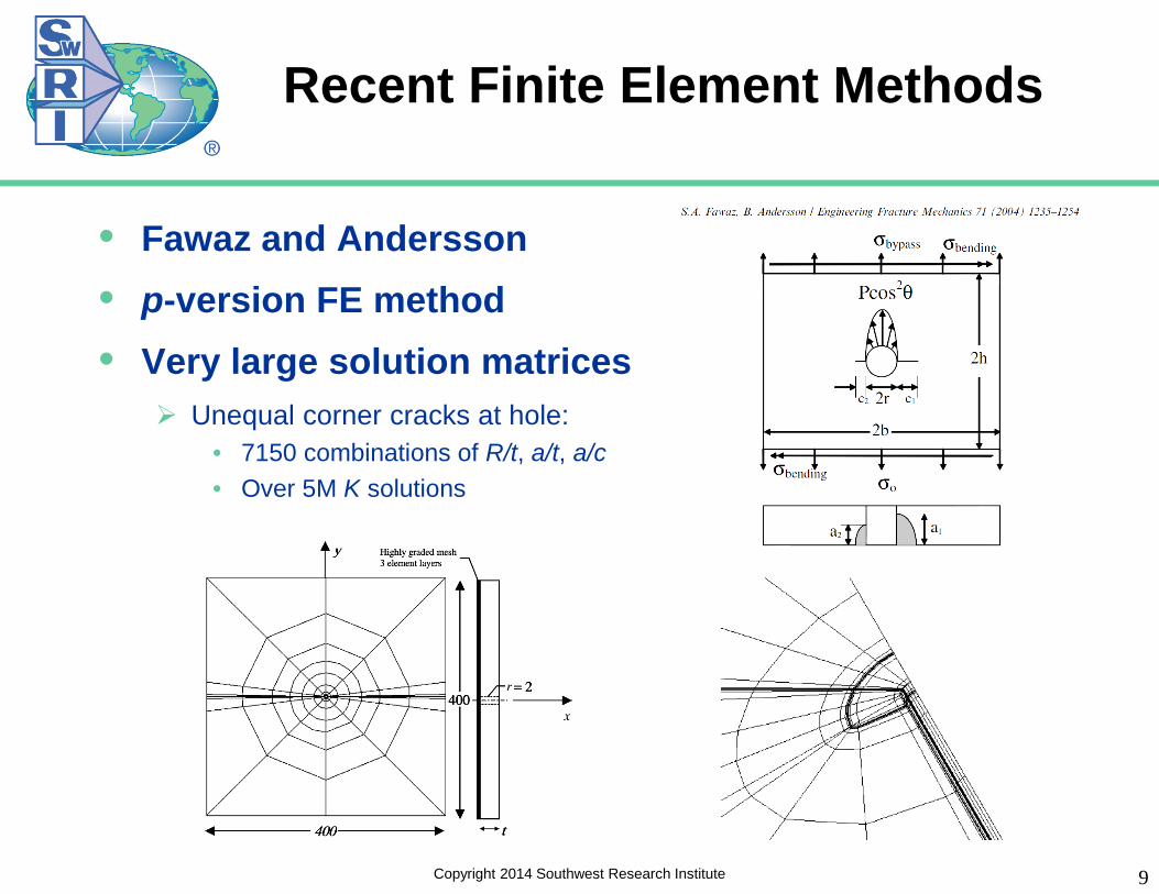
Recent Finite Element Methods
• Fawaz and Andersson • p-version FE method • Very large solution matrices
Unequal corner cracks at hole: • 7150 combinations of R/t, a/t, a/c • Over 5M K solutions
9 Copyright 2014 Southwest Research Institute
Use of New FE Methods
• Automation and advanced computer power makes it possible to generate millions and millions of solutions
• How best to employ these new results? Calculate what you need, when you need it? Evaluate/update/extend legacy solutions? Develop “simple” equations? Use directly as large interpolation tables?
• Challenges: Computation time still too long for real-time use in design Very large tables large computer memory requirements How to address other finite geometry effects? (e.g., offsets, plate width) How to verify that all solutions are correct?
10 Copyright 2014 Southwest Research Institute
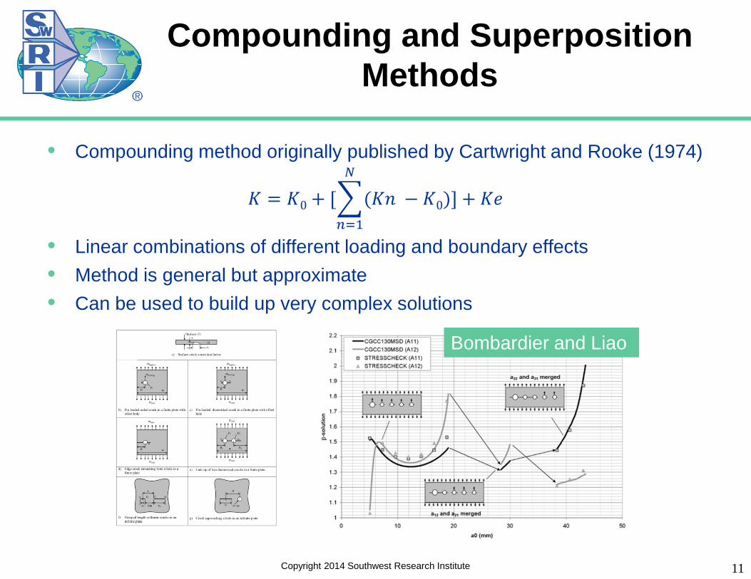
Compounding and Superposition Methods
• Compounding method originally published by Cartwright and Rooke (1974)
𝐾 = 𝐾0 + [�(𝐾𝐾 − 𝐾0)] + 𝐾𝐾𝑁
𝑛=1
• Linear combinations of different loading and boundary effects • Method is general but approximate • Can be used to build up very complex solutions
11
Bombardier and Liao
Copyright 2014 Southwest Research Institute

Compounding and Superposition Methods: New TC23 Solution
Unequal Through Cracks at Hole
12
Y. Bombardier and M. Liao, SDM Conf., 2010.
Copyright 2014 Southwest Research Institute

Compounding and Superposition Methods: New TC23 Solution
Unequal Through Cracks at Hole
13 Copyright 2014 Southwest Research Institute

Compounding and Superposition Methods: Unequal Corner Cracks at Hole
14 Copyright 2014 Southwest Research Institute
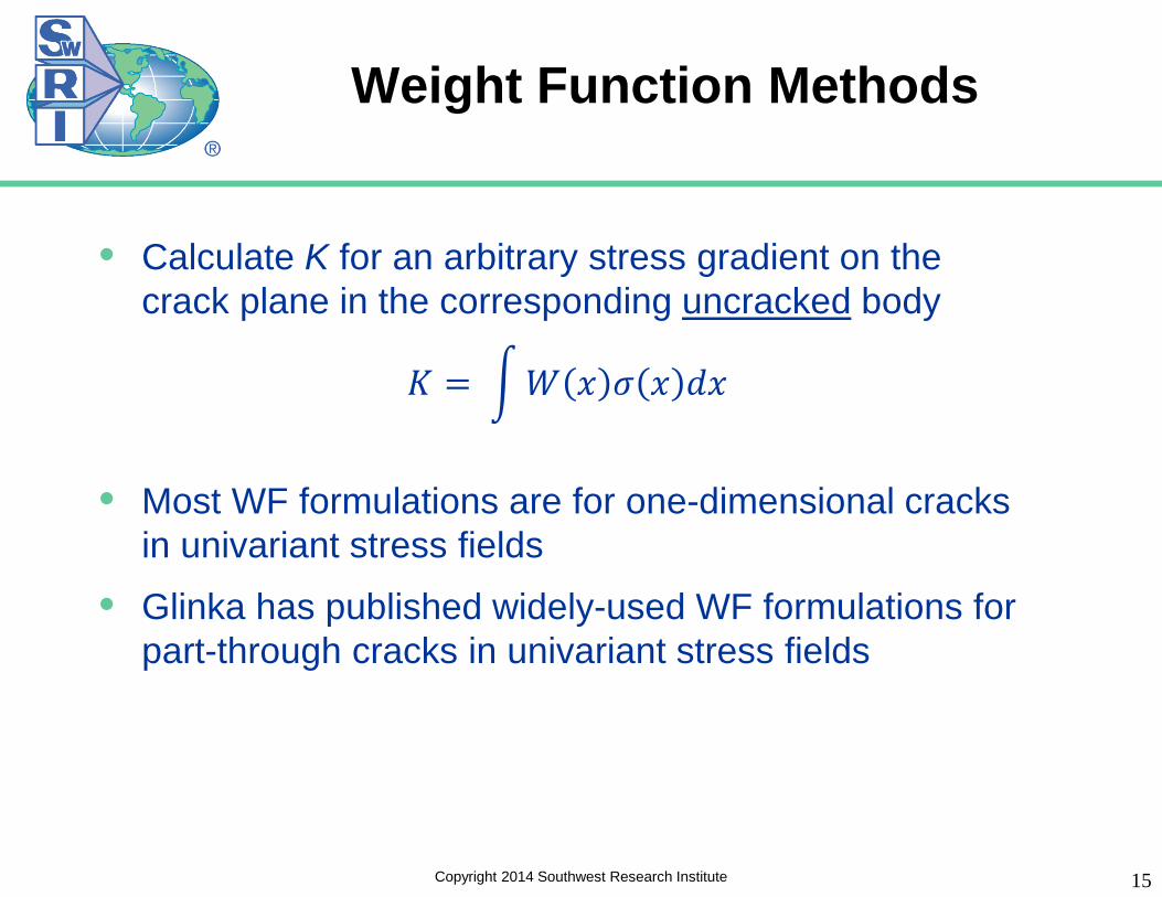
Weight Function Methods
• Calculate K for an arbitrary stress gradient on the crack plane in the corresponding uncracked body
𝐾 = �𝑊 𝑥 𝜎 𝑥 𝑑𝑥
• Most WF formulations are for one-dimensional cracks in univariant stress fields
• Glinka has published widely-used WF formulations for part-through cracks in univariant stress fields
15 Copyright 2014 Southwest Research Institute
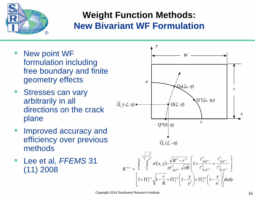
Weight Function Methods: New Bivariant WF Formulation
• New point WF formulation including free boundary and finite geometry effects
• Stresses can vary arbitrarily in all directions on the crack plane
• Improved accuracy and efficiency over previous methods
• Lee et al, FFEMS 31 (11) 2008
x
y
• QR(ξ0, η)
• Q(ξ, η)
• Q*(0, η)
• Q’(ξ0, η0) yQ (-ξ, η) •
• xQ (ξ, -η)
c
a t
W
( )
dxdyxx
yy
Rr
RrRyx
K
cacaca
a ayc
QQca ca
y
ca
cax
ca
ca
′−Π+
′
−Π+−Π+
++
−
=∫ ∫
−
1111
1,
,3
,2
,1
0
1
02
2
2
2
2
22
,
2
2
,
,
,
,
,
ππσ
Copyright 2014 Southwest Research Institute 16

• These univariant and bivariant WF SIF formulations require large number of accurate reference solutions over wide geometry ranges
• Uniform tension, linear gradient loadings on crack face
• Hybrid FADD3D BE-FE software used to generate these solutions Highly accurate Limited meshing requirements
Weight Function Methods: Numerical Generation of
Reference Solutions
Copyright 2014 Southwest Research Institute 17

Weight Function Methods: New Family of Univariant and
Bivariant WF Solutions
• Two geometry classes Cracks in plates Cracks at holes
• Wide geometry ranges • Formulated for speed
Pre-integration for series summation Dynamic tabular interpolation
CC11 SC17
TC11 TC12
EC05 EC05
CC09 SC19
EC04 EC04
CC08 SC18 TC13 CC10 SC29
Copyright 2014 Southwest Research Institute 18
SC31 SC30
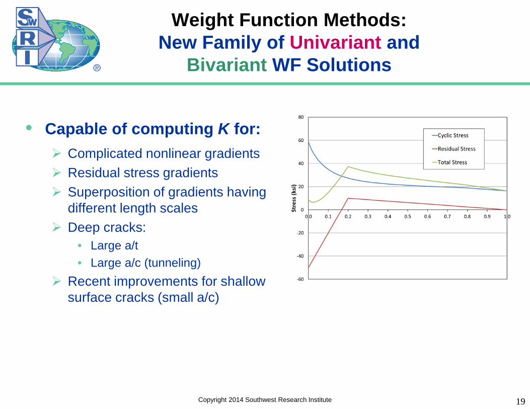
Weight Function Methods: New Family of Univariant and
Bivariant WF Solutions
• Capable of computing K for: Complicated nonlinear gradients Residual stress gradients Superposition of gradients having
different length scales Deep cracks:
• Large a/t • Large a/c (tunneling)
Recent improvements for shallow surface cracks (small a/c)
Copyright 2014 Southwest Research Institute 19

Weight Function Methods: Verification of CC10
Bivariant Corner Crack at Hole
20
96 different geometry combinations
Bore tip Surface tip
Copyright 2014 Southwest Research Institute
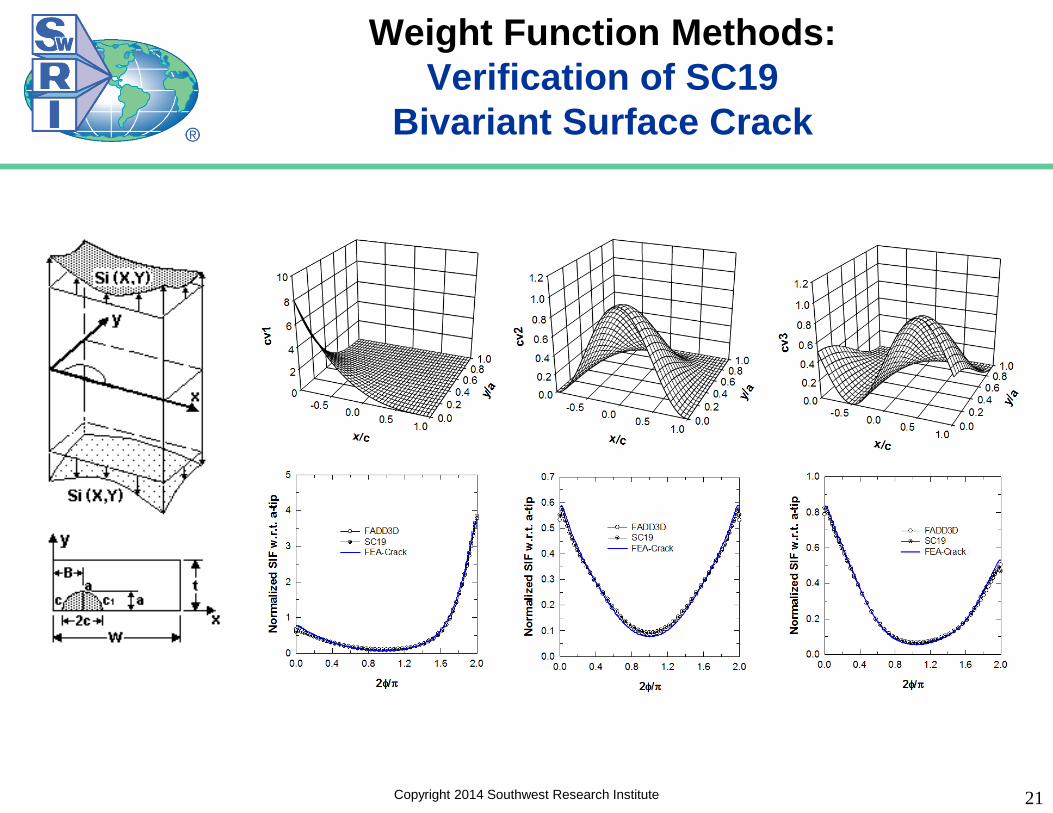
Weight Function Methods: Verification of SC19
Bivariant Surface Crack
21 Copyright 2014 Southwest Research Institute

• Stress field ahead of arbitrary notches is a function of the notch root radius and the total notch depth
22
Weight Function Methods: Derivation of New Solutions for
Cracks at Arbitrary Edge Notches
Copyright 2014 Southwest Research Institute

• Corner/Surface/Through crack at elliptical or angled edge notch • Surface/Corner/Through crack at embedded slot or elliptical hole • Surface/Corner/Through crack at round hole with broken ligament
Weight Function Methods: Family of New Solutions for Cracks at
Arbitrary Notches/Slots/Holes
Copyright 2014 Southwest Research Institute 23

Weight Function Methods: Family of New Solutions for Cracks at
Arbitrary Notches/Slots/Holes
Copyright 2014 Southwest Research Institute 24
Note geometry details

Challenges and Resolution
• K solutions have been accumulating for 30+ years • Multiple solutions are now available for the same geometry
They don’t all have the same geometry scope They don’t all have the same loading capabilities They don’t all give the same answers! They are not easily reconciled! Which is the most accurate?
• Other factors make it even more difficult to compare and evaluate different solutions For example, how to treat K solutions at the free surface for a part-through
crack?
• The path forward: intelligent combination of experience and methods
25 Copyright 2014 Southwest Research Institute

Software Sustainment (Example)
• Multiple K-solutions cases were available in NASGRO for corner-crack-at-hole geometries CC02, CC04, CC07 (legacy models) CC08, CC10 (newer WF models)
• These different crack cases all had slightly different capabilities, but they sometimes gave inconsistent results, leading to confusion
• It was not clear which solution was the most accurate • Should we attempt to adjust the existing solutions, or
should we attempt to develop a new (replacement) solution?
Copyright 2014 Southwest Research Institute 26
Review of Existing Solutions
• Detailed review of the existing solutions (CC02/04/07/08/10) confirmed inconsistency of results
• No easy way to reconcile these inconsistencies Some solutions use multiple correction factors or equation fits on top of the
original Newman-Raju FE results Some solutions use completely different matrices of results that are
themselves fundamentally inconsistent with each other
• The original Newman-Raju results, while remarkably accurate in many cases, are based on ~1980 technology (meshes with 7900 DOF) and have limited geometry ranges
Copyright 2014 Southwest Research Institute 27

Review of New Fawaz-Andersson Solutions
• The new Fawaz-Andersson solutions (2004) appeared to be reliable and superior Employed much larger and more sophisticated FE models Agrees with Newman-Raju results in many cases Covers a much wider overall geometry range Includes pin loading results in addition to tension and out-of-
plane bending The raw F-A database had a few obvious problems that
needed to be fixed (challenging due to large size of database)
F-A data were also available for consistent extension to solution for two unequal corner cracks at hole
Copyright 2014 Southwest Research Institute 28
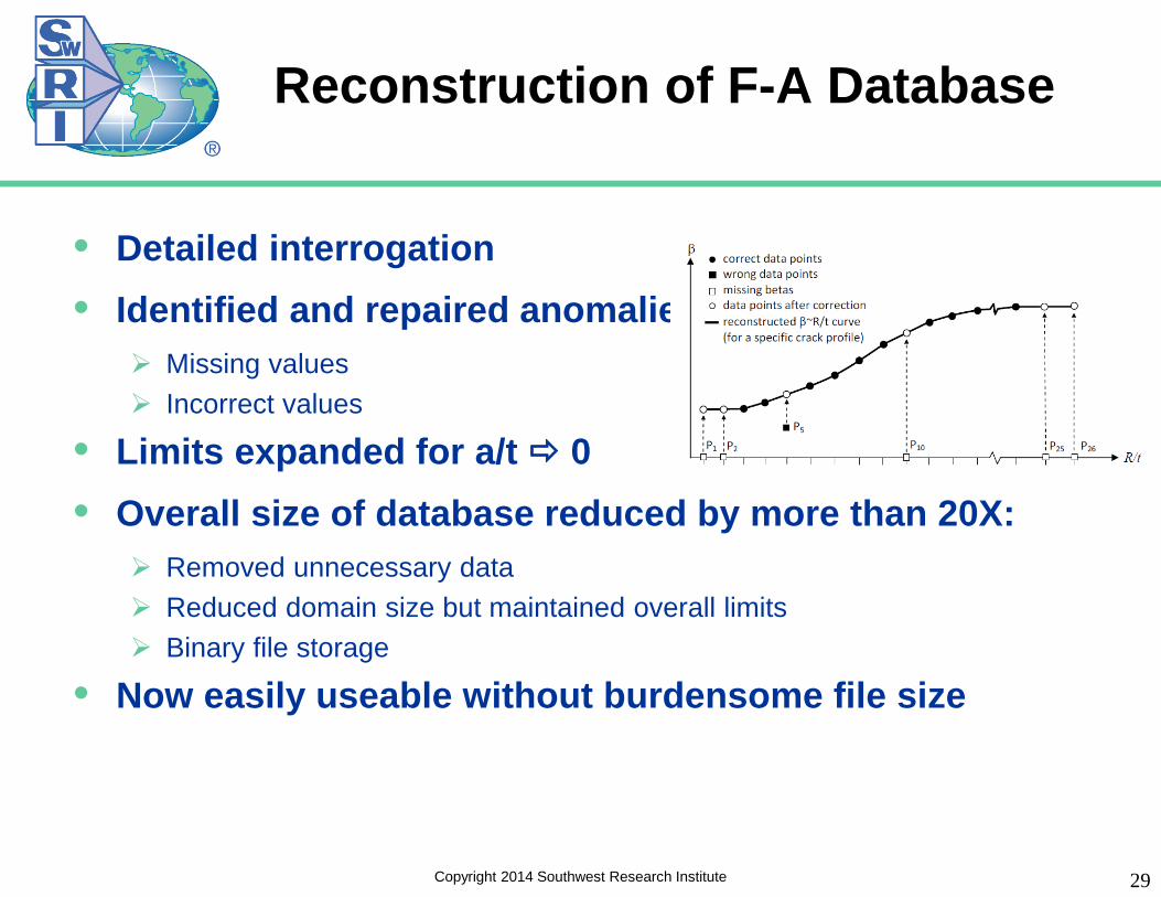
Reconstruction of F-A Database
• Detailed interrogation • Identified and repaired anomalies:
Missing values Incorrect values
• Limits expanded for a/t 0 • Overall size of database reduced by more than 20X:
Removed unnecessary data Reduced domain size but maintained overall limits Binary file storage
• Now easily useable without burdensome file size
Copyright 2014 Southwest Research Institute 29

New Single-Corner-Crack-at-Hole Solution (CC16)
• Start with (repaired) Fawaz-Andersson database 0.1 ≤ a/c ≤ 10, 0 ≤ a/t ≤ 0.99, and 0.1 ≤ R/t Remote tension, remote out-of-plane bending, pin loading
• Use existing CC08 WF solution to guide refinements New finite width correction factor Hole offset correction factor a/t = 0 solution (from Kt considerations)
Copyright 2014 Southwest Research Institute 30
• Generate additional FE solutions for verification

New Unequal-Corner-Crack-at-Hole Solution (CC17)
• Start with (repaired) Fawaz-Andersson database 0.2 ≤ a/c ≤ 5, 0 ≤ a/t ≤ 0.95, and 0.125 ≤ R/t ≤ 10 Remote tension, remote out-of-plane bending,
pin loading
• Derive new “equivalent hole” method for finite geometry effects Account for effects of crack on the other side of
the hole Then use new CC16 correction factors Validated with additional FE solutions
• Entirely consistent with CC16 • Verified with extensive additional
numerical analyses
31 Copyright 2014 Southwest Research Institute

Related Ongoing Development Activities
• Improved finite-width correction factors for pin loading
• Hybrid through crack (TC) and corner crack (CC) at a hole model
• Through crack at rectangular edge notch with rounded corners, univariant WF
Copyright 2014 Southwest Research Institute 32

Model Verification & Validation
• Verification: Process of determining that a model implementation accurately represents the developer’s conceptual description of the model and the solution to the model
Math issue: “Solving the equations right”
• Validation: Process of determining the degree to which a model is an accurate representation of the real world from the perspective of the intended uses of the model
Physics issue: “Solving the right equations”
33 Copyright 2014 Southwest Research Institute

Hierarchical Approach to V&V
• Following the paradigm of ASME V&V 10-2006, V&V should be performed step-by-step in a hierarchical, building-block approach
34
Lifetime Calculation
Crack Driving Force Model
Environment Model
Material Model
Geometry Model
Stress Model
Copyright 2014 Southwest Research Institute

Detailed Draft Hierarchy for V&V of FCG Lifetime Analysis
35
Material Model
Material Similitude
K
Copyright 2014 Southwest Research Institute
Some Current and Future Challenges
• Crack configurations with many degrees of freedom Cracks at countersunk holes Cracks at lugs Multiple-site damage, including crack interaction and link-up Continuing damage Cracks in stiffened structures
• Irregular crack shapes (not straight or part-elliptical) • Contact stresses at fasteners • Constraint loss for crack tips near surfaces • Structural load redistribution • Speed issues: faster computers vs. bigger problems
Copyright 2014 Southwest Research Institute 36

Concluding Remarks
• K solutions have been available to support engineering analysis for fracture control for 40+ years Many legacy solutions have been used for 30+ years
• Recent resurgence of interest and activity in developing new and improved K solutions Faster computers, improved numerical methods, new formulations
• New K solutions are more widely available today (and easier to use) in sophisticated engineering software
• Continued collaborations between the research community and industry are needed to ensure that this technology growth continues and addresses the significant number of remaining needs and challenges
Copyright 2014 Southwest Research Institute 37

Key References
Copyright 2014 Southwest Research Institute 38

Copyright 2014 Southwest Research Institute 39
Benefiting government, industry and the public through innovative science and technology
®
Southwest Research Institute®