nasi - nasa panel. this temi)erature differential can cause differential expansion an(t...
TRANSCRIPT

NASA Technical Memorandum 4372
Structural Performance of
Two Aerobrake Hexagonal
Heat Shield Panel Concepts
John T. Dorsey
Langley Research Center
Hampton, Virginia
James W. Dyess
Virginia Polytechnic Institute and State University
Blacksburg, Virginia
NASI National Aeronautics and
Space Administratior_
Office of Management
Scientific and TechnicalInformation Program
1992
https://ntrs.nasa.gov/search.jsp?R=19920015558 2018-11-28T00:02:01+00:00Z

Abstract
Structural sizing and performance are presented
for two structural concepts for an aerobrake hexag-
onal heat shield panel. One concept features a
sandwich construction with an ahmfimnn honeycomb
core and thin quasi-isotropic graphite-epoxy facesheets. The other concept features a skin-rib is<)-
grid construction with thin quasi-isotropie gralflfite-
epoxy skins an(t graphite-epoxy ribs oriente(t at
0 °, +60 °, and -60 ° along the panel. Linear static,linear bifllrcation truckling, anti nonlinear static anal-
yses were perfornled to compare the structural per-
formance of the two panel concepts and assess their%asihility for a hmar transfer vehicle aerobrake
application.
Introduction
There is great interest in inanned exploration ofthe solar systeln, beginning with a return to the
Moon and followed by a manned nfission to Mars
(ref. 1). Since the vehicles required for these mis-
sions are too large and massive to he placed in orbit
by a single launch of the Space Shuttle or a heavy-liftlaunch vehieh_, some on-orbit assembly and construc-
tion will likely be required (ref. 2). A large portion of
the mass of the hmar transfer vehicle (LTV) and the
Mars transfer vehicle (MTV) consists of the propel-
lant required for propulsive braking. Aerol)raking,which uses aerodynamic drag forces (create(t during
an aeropass through a i)lanetary atmosphere), can
be used as an alternative to propulsive braking toachieve the reduction in velocity require<l to enter <)r-
bit around a planet. Thus, by reducing the amount
of propellant require(t for a mission, aerot)raking pro-vides a potentially eifectivc way to reduce the ini-
tial mass of hmar and Mars transfer vehicles (refs. 3and 4).
For LTV's and MTV's that use aerobraking,
spacecraft components are packaged on the leeward
side of tile aerobrake, as shown in figure 1, so that theaerobrake protects the components from the extreme
thermal environment generated during the aeropass.
The aerobrake design selected for a particular mission
will be influenced by many t)aralneters, including thetotal mass of the spacecraft, maximum deceleration
rate limit (crew physiological requirement), maxi-
nmm allowable stagnation telnperature (thernlal pro-
tect.ion requirements), and lift-to-drag ratio required(to maintain control). In order for an aerobrake to be
viable for a mission, it. must be lightweight; have min-
imal packaged voluine for transporting to low Earthorbit; be easily constructed on orbit; and in somecases, be reusable.
One aerobrake structural concept that is <tesignedto be constructed on orbit and has received consider-
able attention is presented in references 5 and 6. Thisaerobrake is 120 ft in diameter and was sized for an
MTV having a total st)aeeeraft nlass of 450 000 Ibm.
This concept, consists of a lightweight tetrahedral
truss with hexagonal heat shield l)anels that are at-
tached to the truss at, (tiscrete points (see fig. 2(a)).Because sandwich panels are very efficient fl'om a
structural I)erformance and mass standpoint, the
hexagonal panels studied in these references used
sandwich construction. Equations are presente(t inreferen('es 5 and 6 for sizing mininmm mass san(t-
wieh panels based on a transverse pressure loa(t anda nlaxinmm (teflection criterion.
An isogrid structural concept is also eonsidere<t
for the heat shiel(t panels because isogri(t construe-
Lion (:all result in lightweight t)ane] designs (ref. 7).Ill ad(tition, there may be other nonstructural con-
siderations that make the isogri(t structural concept
an attractive alternative to the san(twich design. Forexample, the open structure of the isogrid allows the
load-carrying ribs to be easily inspected for damage
t)efore certifying a reusable aerobrake for the next
mission. Additional structure require(t to accommo-
date loads introduced at the panel support pointsmay be minimized because connections can be made
at the isogrid rib intersections. This can be con-
trasted with sandwich t)anels, where mass advantages
pre(ticted from fl_asit)ility stu(ties are "often lost in
the re(hwtion to design practice, especially in the de-
sign of joints and attachments" (ref. 8). Anotherpotential problenl with sandwich panels is that aer-
obrake heating may lea(t to large temperature differ-ences between the front and 1)ack faces of the sand-
wich panel. This temI)erature differential can cause
differential expansion an(t contra('tion in the two facesheets, which can t)lace the core material under ten-
sion, and if sufficient stress is generated, set)arate theface sheets from the core (ref. 9).
Thus, it is worthwhile to study the feasibility oftlw isogri(l panel concept as an alternative to tile
sandwich concept at, an early stage of the aerobrake
design t)rocess. In this paper, results are presented
for both the sandwich and isogrid panel concepts.
Two of tile four panel-to-truss attachment concepts
studie(t in reference 6 are use(t in lifts study (seefig. 20))). These attachment concepts were chosen
because they result in the largest and smallest masses
per unit area for the sandwich panel. Tile prelim-inary design methods presented in reference 6 are
used in the t)resent stu(ly to size sandwich panels for
an LTV aerobrake (which is 45 to 50 ft in diame-ter). Results that are representative of the mass an<t

performancethat canbe obtainedfor the isogridpanelconceptarepresentedandcanbeusedtoassessthefeasibilityof theisogridconceptfor anaerobrakeapplication.If the performanceandmasspenaltiesfor isogridconstructionaredeterminedto besmallcomparedwith a sandwichdesign,thena morein-depthstudyof theisogridconceptwill bewarranted.
All importantlimitationof thepreviousstudieshasbeenthat theheatshieldpanelsaredesignedus-ingonlyaglobalpanelstructuraldeflectioncriterion.However,amoreimportantdesignconsiderationforsomethermalprotectionsystems,suchasthetilesontheSpaceShuttle,is thelocalcurvaturein thestruc-ture overthe lengthof tile tile. In orderto relatethermalprotectionsystem(TPS)deflectionlimitstothepaneldesign,equationsarederivedin thepresentpaperto calculatefrom asetof transversedisplace-mentsthe local radiusof curvature(ROe) inducedin the panel.TheseequationsestablishonepossiblerelationshipbetweenlocalpanelcurvatureandTPStile sizeanddeflectionlimits.
Nomenclature
A
CL _ C2, c3
D
d
E
F
G
h
L
Lrib
M
N
_t
area, in 2
constants in equation (5)
panel bending stiffness, in-lbf
panel diameter, in.
Young's modulus, lbf/in 2
rib frequency (see eq. (4))
shear modulus, lbf/in 2
height, in.
length, in.
total rib length, in.
mass, lbm
membrane stress, lbf/in.
number of 0 ° plies in rib laminate
P
R
ROC
t
Wa, w b , Wc
pressure
radius, in.
radius-of-curvature, in.
thickness, in.
displacement normal to panel
surface, in.
normal displacements associated
with points a, b, and c, in.
Wmax
x_y,z
o_
0
12
P
Subscripts:
c
eft
/HP
IP
Irtm
R
rel
rit)
sk
SP
tcs
TPS, 1
g,Y
0
maximum normal panel displace-
ment, in.
orthogonal coordinate system in
three-dimensional space
panel coefficient (see eq. (12))
circumferential direction
Poisson's ratio
material density, lbm/in 3
core
effective
face sheet
hexagonal panel
isogrid panel
minimum inass
radial direction
skin center relative (displacement)
isogrid ribs
symmetric lay-up about, the
midplane
isogrid skin
sandwich panel
triangular cell size
thermal protection system tile size 1
laminate axes (x is along the fiber)
circumferential direction
Hexagonal Heat Shield Panel Design
Concepts
In this study the aerobrake, which is part of an
LTV, has an overall diameter of 44 ft (see ref. 10).The heat shield panels are attached to nodes on the
windward face of the tetrahedral truss (see fig. 2(a))and function as a continuous aerobraking surface.
The heat shield panels are assumed to be flat to sim-
plify the preliminary design process as in reh'rences 5and 6. The TPS used on the heat shield panels could
be ablative material or reusable tiles, depending on
the specific mission requirements; the TPS is appliedto one face of the structural panel as shown in fig-
ure 3. Any additional structural stiffness (which is
assumed to be small) provided by the TPS is also ne-
glected to simplify the preliminary design process. In
this section, general design considerations for hexag-onal heat shield panels will first be discussed, fol-
lowed by specific design details for the sandwich and

isogridpanelconcepts.Finally,a methodologyforsizingTPStilesbasedon a local structural radius ofcurvature will be examined.
Design Considerations
There are several design considerations associated
with the hexagonal heat shield panels. In reference 6,it is shown that the size and dimensions of the
hexagonal heat shield panel are deternfined primarily
by the aerobrake diameter, tile number of rings in
the tetrahedral support truss, and the panel supportlocations. In tile present study, the hexagonal panels
are also constrained to fit inside the cargo bay of the
Shuttle Space Transportation System, which limits
the panel diameter to a maximum of 14 ft. The
largest possible diameter panel is desired because itnfinimizes the truss and panel part counts anti thusreduces the amount of on-orbit construction required.
The largest panel permissible with panel support
concept, A has a diameter of 121.13 in. and attachesto a 2-ring support truss. Similarly, the largest panel
permissible with support concept D has a diameterof 150.34 in. and attaches to a 3-ring support truss.
Although the actual aerodynamic pressure dis-
tribution acting on the aerobrake during reentry isnonuniform, a uniform distribution is assumed to
simplify the preliminary design process. The mag-
nitude of this uniform pressure is derived from theaerobrake inertia force due to a constant decelera-
tion rate. For a spacecraft mass of 25 500 lbm, a 59nmximum deceh'.ration rate, a cross-sectional area of
219 000 in 2, and a factor of safety of 1.4, equation (1)
from reference 6 gives a pressure load of 0.815 psi,
which is applied normal to the plane of the panel.
Sandwich Panel Description
The sandwich panels used in the present studyfeature an aluminum honeycomb core and
graphite-epoxy face sheets (see fig. 3). The honey-comb core has a density p(, of 0.00231 lbm/in 3
(4.0 lbm/ft3), and the graphite-epoxy materialused in the face sheets has the following lamina
properties: Ez = 40.8 x 10⁶ psi, Ey = 1.0 x 10⁶ psi,
Gxy = 0.6 x 10⁶ psi, r,_jz = 0.3, and a ply thicknessof 0.005 in. The face sheets are quasi-isotropic,
resulting in an effective laminate modulus Eeff of
14.4 x 10⁶ psi and a material density pf of
0.063 lbm/in a. Minimum gauge for the face sheetswas assumed to be 0.04 in.; this resulted from an
&ply mid-plane symmetric, quasi-isotropie laminate.
Isogrid Panel Description
The isogrid pattern chosen for tile hexagonal
heat shield panels consists of equilateral triangles,
as shown in figure 4(a). Using ribs oriented at.
0 °, +60 °, and-60 ° results in overall isotropic mem-brane stiffness properties for the panel. The mmlber
of equilateral triangular cells along each edge of the
hexagonal isogrid panel is defined as the frequency F
of the panel. A cross section of the isogrid panel is
shown in figure 4(b). In the present study, the ribsare assumed to be blade stiffeners, as shown in the
figure. A fixed ratio of height (hrib) to thickness (trib)is chosen for tile ribs to reduce the number of in-
dependent variables in the feasibility study. Based
on discussions with senior engineers, a rule-of-thumbvalue of 6 was chosen for this ratio. The nmtcrial
used in the isogrid panel has the same properties as
the graphite-epoxy used in the skins of the sandwichpanel. A quasi-isotropie laminate is assumed for the
skin, resulting in an effective laminate modulus of
14.4 x 10⁶ psi. The ribs are designed to carry most
of the loading in the panel, and thus a laminate thatmaximizes the rib extensional moduhls is desirable.
The rib design chosen, a [+45,-45, 0,_]s lay-up, uses
a pair of +45 ° plies to stabilize the 0° plies that run
along the longitudinal axis of the rib. Representativevalues of n, together with the resulting total nmnber
of plies in the rib, tile total rib thickness, and the ribefl'ective laminate modulus, are tatmlaled in table I.
Since tile attachment points for support con-
cept A are at vertices of the hexagonal panel, no
complications arise as the rib frequency is varied.
However, with support concept D the attachment
points are in the interior of the panel two-thirds ofthe distance fl'om the panel center to tile edge of the
hexagon (see fig. 4(e)). When the rib frequency is an
integral multiple of 3, there will be an intersection
of ribs at these points, providing a stiff attachmentor support point for the panel. For all other rib fre-
quencies, the support points will fall in the interior
of a triangular cell, leading to a very "soft" support
point. In these cases, three additional members areadded to the isogrid pattern to provide attachment
points on ribs, as illustrated in figure 4(c) for the caseofF=2.
TPS Tile Sizing
In general, TPS tiles such as those used on the
Shuttle are very fragile and are separated from theunderlying structure by a strain isolation pad (SIP).
However, for a given tile size, there will exist a de-
flection limit in the underlying support structure that
cannot be exceeded without causing the tile to sep-arate from the structure because, of failure of the
SIP. A local induced radius of curvature can be cal-
culated from transverse panel deflections, as shown
in figure 5(a), and then related to an allowable tile
3

deflection (WTPS) and tile size (L1, L2), as illustrated
in figure 5(b). Two design approaches for the struc-
tural/TPS system are possible. In the first approach,
the structure is designed without regard for TPS de-flection constraints, and once the type of TPS tile
and its maximum allowable deflection are specified,a maxinnun tile size can be calculated. In tile second
approach, a required TPS tile size and a maximum
allowable deflection are specified, and the structure
is designed with sufficient stiffness such that the nfin-
immn induced ROC of the panel is acceptable for the
TPS design. In general, a larger minimum ROC im-plies a flatter deflected structure, which should allow
more freedom in the TPS design process.
Analysis
This section describes the methods used to size
the sandwich and isogrid hexagonal panels. The
Engineering Analysis Language (EAL) finite element
program was used to model and analyze the sandwich
and isogrid panels (see rcf. 11). The equations thatrelate normal panel displacements to an inducedradius of curvature are also derived.
Sandwich Panel Model
smallest deflection when subjected to the design load.
The structural performance of the isogrid panel canthen be compared with the performance of the sand-
wich panel having identical mass. Once the panel
mass and planform area are specified, the design pa-
rameters that can be varied are the skin thickness,the total length of ribs, the rib thickness, and the ribheight.
The total mass of the isogrid panel is
_llP = p(AIptsk + Lribhribtrib) (1)
Since the rib height hri b is chosen to be 6 times tile
rib thickness trib, the total mass of the skin stringerpanel becomes
_I1P =p(AIptsk-t-Lrib6t2ib) (2)
where tsk is the panel skin thickness and Lri b is the
total length of ribs used in the panel. Tile area ofthe isogrid hexagonal panel (Atp) is
Equations (28) and (29) in reference 6 are used to
design the sandwich panels with support concepts Aand D. The finite element discretization used for the
sandwich panel models is identical to that found in
reference 6 and is illustrated in figure 6.
For an isogrid panel, the number of subdivisions
along a panel edge, or the rib frequency F, is a major
design parameter and will determine the total lengthof ribs for the panel. The rib frequency, illustratedin figure 4(a), is defined by"
Isogrid Panel Model
Geometry. The isogrid panel skin was dis-
cretized into a uniform triangular-element pattern,
as shown in figure 7, so that the resulting element
boundaries would lie along rib lines. The isogridpanel skin is modeled with triangular plate elements,and tile ribs are modeled with beams with a rect-
angular cross section. In order to correctly modelthe rib stiffness, the rib neutral axis is offset from
the skin neutral axis by a distance equal to half the
skin thickness plus half the rib height, as shown infigure 7.
Design procedure. The approach used to size an
isogrid panel was to choose a panel mass and deter-
mine the most structurally efficient way to distributethat mass between the ribs and the skin. hfitially,sandwich panel designs were determined for each of
the two panel diameters (one associated with sup-
port concept A, and one with support concept D) andtheir mass was taken as the total mass for the respec-
tive isogrid panel. Since mass is held constant, the
most efficient isogrid panel is the one that gives the
F- driP2Ltcs (4)
where drip is the hexagonal panel diameter and Ltcs
is the length of the side of a triangular cell formed
by the ribs. When a rib frequency is chosen forthe panel, only two variables remain undefined inequation (2): the skin thickness and the rib thickness.Thus, a value of skin thickness can be chosen and the
corresponding rib thickness calculated for a constant
mass panel with equation (2). The effective modulusof the skin remains constant as the skin thickness
(which is assumed to be a continuous function for this
study) is varied. However, the modulus of the ribswill increase as the rib thickness is increased because
a greater percentage of the rib laminae are orientedin the 0 ° direction (see table I).
Radius-of-Curvature Derivation
A general expression for relating three adjacentdisplacements on the analysis model to a local radius
of curvature, as shown in figure 5(a), is desired. The
three displacements are assumed to be coplanar and
4

equallyspacedfor thisanalysis.Thegeneralformfortheequationof acircle(seeref. 12)is
y2 + z 2 +cly -t- c2z + c3 = 0 (5)
The locations of the three deflected points used to de-
rive the ROC arc point a: y = -L, z = -Wa; point b:y = O, z = --Wb; and point c: y = L, z = -we. Sub-
stituting these three points into equation (5) resultsin three equations with the three unknown coeffi-
cients el, c2, and c3. The three equations were solved
symbolically using the program Theorist (see ref. 13),with the following result:
(we- (,q - + +2c2)wc 2w b + wa
(6)
+ +C2 = (7)
Wc -- 2w b -t- Wa
wb r[2L2 + wc (we- Wb) q- Wa (Wa - Wb)lnjc3 = (8)
we -- 2w b + Wa
Tile equation for the induced radius of curvature is
Whereas equation (9) relates the induced ROC
to normal displacements on the structural panel,another equation can be derived that relates the ROC
to tile size (or span) requirements and the magnitude
ofa maximmn allowable deflection (see fig. 5(b)). Fora tile with dimension L1 and a deflection limit of
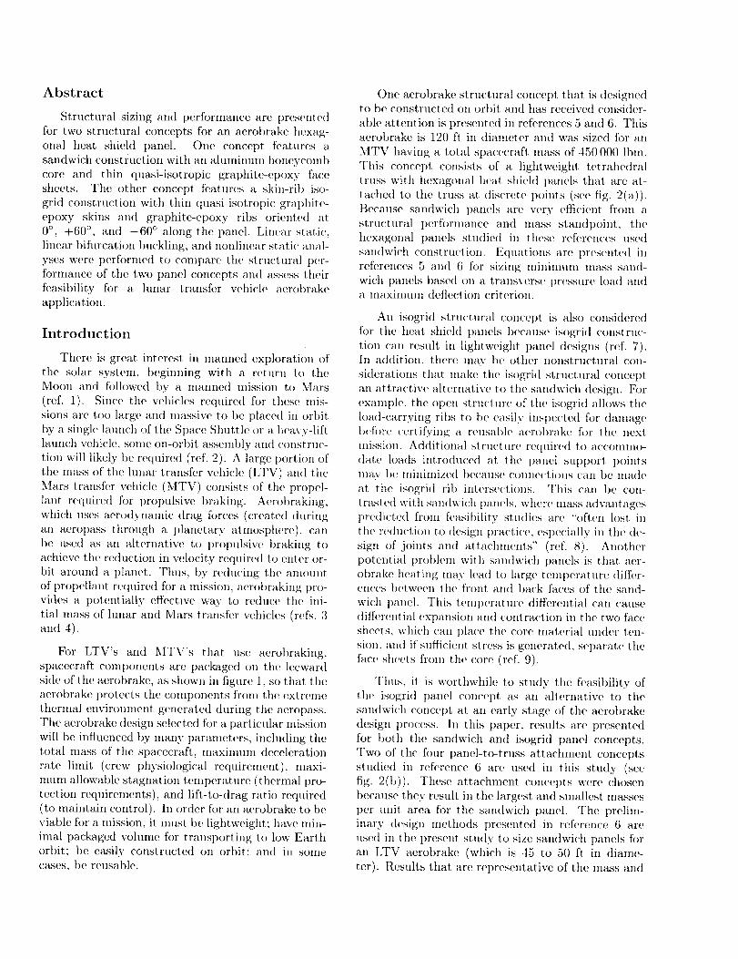
WTpS,1, an expression for the ROC is
(ROC - WTpS, 1 + L 2 = ROC 2 (10)
This expression can be expanded and when solvedfor ROC yields
1(ItOC = _ WTpS, 1 + --WTpS,1
(11)
Results and Discussion
Sandwich Panels
One of the design parameters that must be spec-
ified when sizing sandwich panels with the equa-tions in reference 6 is the panel deflection criterion
Wmax/dHp , defined as the ratio of the maxinmm
panel deflection to the panel diameter. In the current
study, a panel deflection criterion of 0.01 was chosen
to size the sandwich panels. This deflection criterion,
together with the material properties and applied
pressure loading described previously, resulted in the
core and face sheet thicknesses listed in figure 6 for
simply supported sandwich panels. For both panel
support concepts, the resulting face sheet thicknessis the minimum gauge value of 0.04 in.
Linear solutions. The maximum deflections
and ROC's for the two hexagonal sandwich panels(support concepts A and D) subjected to a uniform
pressure load are listed in table II for simply sup-
ported and clamped boundary conditions. For sup-
port concept A with simply supported boundary con-ditions, the maximum deflection of 1.19 in. results in
a calculated value of Wmax/dHp = 0.0098, compared
with the design value of 0.01. Since clamping the
support points enforces zero slope at. those points,
the panel maxinmm displacement is substantially re-duced (by 50 percent when the same sandwich design
is used). Since the slope is essentially zero at the sup-
ports because of symmetry, changing to clamped con-
ditions for panel support concept D has a negligibleeffect on the maximum panel deflection, as indicated
in table II. Tile inaximmn deflection yields a calcu-
lated value of Wmax/dHp = 0.0090 h)r both boundary
conditions, which is 10 percent less than the designvalue.
Nonlinear solutions. Since tile nlaximmn
panel deflections were on the order of the panel thick-
nesses for both support concepts A and D, nonlin-
ear finite element analyses were performed to deter-mine the importance of geometric nonlinearities on
the predicted performance of the sandwich panels.
The results given in table II for support concept A
show that small decreases in deflections are predictedby the nonlinear solution, compared with the linearsolution. The small decreases in deflections indicate
that very little structural stiffening is being induced
by the membrane stresses. A slightly larger nonlinear
effect is noted for the panel with support concept D,however, because the ratio of the plate thickness to
the plate diameter is smaller for support concept Dthan support concept A.
The local ROC was also calculated (with eq. (9))from the nonlinear displacements for the panels with
support concepts A and D. For support concept A
with simple supports, the minimum ROC is 618 in.,and when the supports are clamped, the minimum
ROC increases to 848 in. For support concept D,
the type of boundary conditions (simply supportedversus clamped) has very little effect on the mini-
5

mumROC,andtheresultingvalueis approximately390 in. for both cases.
Panel eoeflficient. When the equations in ref-erence 6 are used to size a sandwich panel, the
value of panel coeffÉcient a must be specified. The
panel coefficient, which accounts for the shape of the
panel planform and the location and type of panelsupports, is calculated with the results from a fi-
nite clement analysis. The coefficient is defined by
equation (18) in reference 6 and is
'u'max = a pdnp_, (12)DHp
where Wmax is tile maximunl normal deflection.Panel coefficient values were calculated for support
concepts A and D with both the linear and the non-linear results obtained in this study and are listed in
table II. The linear and nonlinear values of a given
in table II for panel support concept A with simply
supported boundary conditions agree very closely.However, if clamped conditions are assumed for sup-
port concept A, the value of o, used to size a sand-
wich panel should be between 0.00389 and 0.00395,as shown in table II. This would lead to a thinner
and lighter weight panel design. The panel coefficient
does not vary significantly (from 0.00100 to 0.00106)when tile boundary conditions are changed from
simply supported to clamped for support concept D.
Panel mass. The equations ((23) and (24)
from ref. 6) for determining the core and face sheetthicknesses for a minimum mass sandwich panel are,
respectively,
' Pc (Wmax/dHp)
1/3
(13)
tf,mm = 0.25 p_ tc,mm (14)Pf
Using these equations to size the sandwich panelsresults in minimmn mass designs for both support
concepts A and D with face sheets thinner than
tile minimum gauge thickness assumed in this study.For support concept A, the minimum mass designhas a face sheet thickness of 0.0229 in., and for
support concept D the minimum mass face sheetthickness is 0.0152 in. The consequence of assuming
a minimum face sheet thickness greater than the
thickness associated with the minimum mass design
(as done in the current study) is given in figure 8. In
this figure, the variation in the percentage of massincrease over the minimmn mass design is shown as
a function of the face sheet thickness. Assuming aminimum thickness of 0.04 in. results in a sandwich
design that is 30 percent heavier than the minimummass design for support concept D, and 9 percent
heavier for support concept A.
Isogrid Panels
Because the clamped boundary conditions im-
proved tile performance for support concept A (but
had no effect on support concept D), only clamped
supports were studied for tile isogrid panels. Thepanels were designed according to equation (2), with
the total isogrid panel mass _Iip set equal to the ap-
propriate total sandwich panel mass value listed in
figure 6 for each of the two support concepts. In thefollowing results, three normal panel deflections will
be discussed: deflections along the ribs, the absolutedeflection of tile center of the skin in the triangular
cells; and the skin-center relative deflection, which isthe deflection of the center of the skin relative to the
plane formed by tile ribs that make up the sides ofthe triangular cell. Also, to calculate values of ROC,
two sets of deflections are considered (as shown in
fig. 9(a)): deflections from the interior of a triangular
cell (skirl) over a rib to the interior of an adjacent tri-
angular cell (skin-rib-skin), and skin deflections thatinclude the center of tile triangular cell (skin-center).
Linear solutions. Tile change in transverse
panel displacements (normalized to the panel diam-
eter) as a function of varying skin thickness is shown
for a panel with support concept A and rib frequency
F = 1 in figure 10. Since the amount of mass is heldconstant, for the designs shown in figure 10, as the
skin thickness is increased, tile amount of materialavailable for the ribs is decreased, resulting in the de-
flection trends shown in the figure. The design with
the smallest value of skin thickness (0.08 in.) has
very large absolute and relative skin deflections, butsmall deflections along the ribs. As the skin thick-
ness is increased, tile skin deflections also decrease;
however, the deflections along the ribs increase be-
cause mass is being taken from the ribs and put intothe skin. As even more material is added to the skin,the ribs have so little material that their stiffness is
no longer significant and the panel behavior begins
approaching that of a very thin uniform plate, andthe deflections become very large again. Thus, there
are two distinct regions present in the displae_,ment
curves given in figure 10: region A, where the lackof skin stiffness dominates the resulting deflections,
and region B, where the lack of rib stiffness domi-nates the deflections. Consequently, there is a most
efficient distribution of panel mass between the' skin

and the ribs that resultsin the best isogridpanelperformance(smallestmaximumdeflection).
Onefindingfronltile linearresultsisthat tilepre-dictedrelativeskindeflectionsarevery largecom-paredwith tile skirl thickness,varyingfroma ratioof 35.4to 7.1for skinthicknessesof 0.08and0.13in.,respectively.Thus,anonlinearanalysismustbeper-formedto obtainaccuratedisplacementinformationfor the isogridpanels.
Anotherfinding is that compressivemeinbranestressesdevelopin the thin skinsof the triangularcellsduringpaneldeformation,andthusskirlbuck-lingbetweentheribsispossibleandmustbeconsid-eredin the paneldesign.Physically,tile total skinloadingdueto tile normalpressureloadingon thepanelcanbe thoughtof as causedby two deflec-tion components(seefig. 9). First, whentire pres-sureis applied,theskill deflectslaterallyasshownill figure9(a). If thetriangularcellis assumedto beclampedat itsboundary(asrepresentedbystiff ribs),the large(i.e.,greaterthan theskin thickness)nor-realdeflectioncausestensilemembranestressesin theskirlbecausetheskinsaresothin that membraneac-tion isdonfinantandverylittle bendingtakesplace.Second,tireskinsareattachedto thetopsoftheribs,andsincetile neutralaxisfor panelt)elrdingiscloseto theneutralaxisof theribs (see.fig. 7), the pres-surecausestheribsto bendasshownin figure9(b).Fortherib deflectionsshown(whichwouldoccurinthecenterof apanelwithsupportcorrceptA, for'ex-arnplc)thesizeof the triangularcell formedby thetopsof the ribs in the deformedstructurewill besmallerthan theinitial undeformedsize.Thus,theactionof theribsin thiscasewouldbe to reducethesizeofthetriangularskirlattachedto thetopsof theribs (shownby the cross-hatchedareain fig. 9(b))andtherebyinduceconlpressivestressesin theskin.Whetherthe net stressin the skin from thesetwodeflectioncomponentsis tensileor compressivewilldependontherelativestiffnessesof theskirlandtheribs.
Isogrid panel buckling design. Since compres-
sive stresses occur in tile skins of the isogrid panels,
buckling must be considered in their design. When
nonlinear analyses were performed, some isogrid de-signs having low skirl stiffness exhit)ited a bifurca-
tion point before the full design toad was reached.(A Mfurcation point is indicated with this nonlinear
analysis when, as the load is increased incrementally,a negative diagonal term occurs in the total stiff-
tress matrix.) This bifilreation point indicated that
a secondary equilibrium path existed for tile isogrid
skins (see ref. 14). In order to determine the lmck-ling modes for tile isogrid panel, a linear bifurcation
buckling analysis was run for an isogrid panel with
support concept A and F = 1.
In the first, mode obtained from the linear bi-
furcation buekling analysis, the skin in a triangularcell section deforms into a half wave with the maxi-
nmm deflection in the center of the skirl (figs. ll(a)and ll(b)). The first six buckling modes of this
panel involve each of the six triangular cells succes-
sively buckling at. essentially identieal critical loads.This first mode is identical to the skirl deformation
shape that results fl'om the transverse pressure load-
ing. Thus, this first mode does not manifest it.-
self in the nonlinear analysis as a bifurcation point
(see ref. 15). The bifurcation Imckling analysis also
identified a second truckling mode that involves skin
buckling into a full wave across triangular cells, as
illustrated in figures 11(e) and 11((t). It. is this bifur-cation point that is identified by the nonlinear anal-
ysis, and this mode can be thought of as a t)ifllrea-
tion point from a nonlinear t)relmekling deformationstate. Since the pretmckling deformations are in fact.
nonlinear, the critical load predicted t)y the linear bi-
fllrcation buckling analysis will not t)e accurate, and
thus the analysis cannot be used for design purposes.
In this study, accept.abh_ isogrid panel designs forsupport concepts A and D are defined to be those
ill which the design load was less than the biflu'ca-tion load. The reason for this critcrioIl is that at
this bifllrcat, ion load, the panel would have to change
its deformation state drastically from a l)retmckling
shape that looks identical to the mode in figures 11 (a)and 11(b) to the postbuckling shape given in fig-
ures ll(c) and ll(d). If this involved very large
changes in deflections, or occurred rat)idly, the re-
sults could be catastrophic for the panel. Tire non-'linear analysis was used to predict this bifurcation
point and eliminate unacceptable designs (i.e., those
with insufficient skin thickness).
Nonlinear solutions. Isogrid panel designs
that did not buckle under tile design pressure, alongwith their maximmn deflections, are tatmlated in ta-
bles III and IV for support concepts A and D, resl)ee-
tively. In both eases, increasing tile rib frequency Fdecreases tire length of the triangular cell sides Lt_:,_,
which leads t.o thinner skills in the acceptable de-
signs. In general, for a given rib frequency, the designthat has tile minimum skin thickness to prevent skirl
buckling, and thus the greatest amount of material
in the ribs, gives the best (i.e., smallest) deflectionperformance for both support concepts.
Tables III and IV also show that for a given
rib frequency, acceptable isogrid panel designs with
support concept D have skirl thicknesses smaller than

thoseforsupportconceptA. Thisoccursbecausethemagnitudesof the compressivenmmbranestresses(Nf¢ and No) for support concept D (see fig. 12)
are significantly smaller than the stresses for con-cept A (see fig. 13). Thus, skin thicknesses required
to resist buckling are smaller for support concept D.
Tile results in figures 12 and 13 also show that sup-
port concept A has a much larger portion of the skinsurface in a compressive stress state than does sup-
port concept D. Representative deflection shapes are
shown for the same isogrid panels with F = 3 and
support concepts A and D in figures 14 and 15, re-
spectively. The relative skin deflections are muchmore pronounced in support, concept D because ac-
ceptable designs had thinner skins than the designs
for concept A. Although these relative skin displace-
ments predicted by the nonlinear analysis are lessthan those predicted by the linear analysis, they are
still large compared with the skin thickness, ms shown
in figure 16.
Tile maximum displacements of the best perform-
ing panels fi_r the two support concepts are compared
in figaro 17. For support concept A, the maximumpanel displacement predicted by the nonlinear analy-
sis for the best design is 1.11 in. and is associated with
an F = 4 design. Similarly, for support concept D,tire maxinmm displacement for the best. design is
0.75 in. and is associated with an F = 3 design. The
results in figure 17 show that the maximum displace-
ment for both support concepts is not very sensitiveto F (or Ltc.,) in the vicinity of the best designs, thus
giving some flexibility to tile panel designer.
Tire nonlinear deflection performance of equal
mass sandwich panels with support concepts A and Dis indicated by tile horizontal lines in figure 17. For
support concept A, the isogrid panel with the best
design has a deflection almost twice as large as that
of tire sandwich panel design. In order to obtain
equal performance, the rib thickness for the F = 4design had to be increased from 0.23 in. to 0.28 in.
As a result, the equal performance isogrid panel
became 26 percent heavier than the sandwich panel.
For support concept D, the isogrid panel designwith F = 3 has a maximum deflection that is only'
57 percent of the sandwich panel deflection. An equalperformance design for an isogrid panel with support
concept D, having a skin thickness of 0.07 in. and a
rib thickness of 0.28 in., has a mass that is 7 percent
less than the sandwich panel mass.
The relationship between the radius of curvature
and the allowable TPS tile size and deflection (as
given in eq. (11)) is illustrated in figure 18. Tileresults show that if an allowable TPS deflection is
specified, the minimum ROC on the deflected struc-
tare increases as the TPS tile size increases. This
means that larger TPS tiles would require a stiffer
support structure. If the structure has already been
designed for mininmm mass based on a deflectioncriterion, the ROC will already be given. In this
case, the maxinnlm TPS tile size will be dictated
by the maximum allowable deflection, and increasing
the deflection limit wilt allow larger tiles to be used.
Skin-center and skin-rib-skin R()C results for tile
isogrid panel designs presented in fgure 17 are given
in table V. Generally, the panels with support con-cept A haw_ larger ROC's than tile panels with sup-
port concept D, and thus would place less stringent
limitations on the TPS design. For both support con-
cepts, the normal deflections from the thin skins onone side of a rib, over the stiff rib to the thin skin on
the other side of the rib, give the smallest ROC. For
isogrid designs with performance equal to the cor-
responding sandwich panels, the panel with supportconcept A haas a mininmm ROC of 124 in. and the
panel with support concept D has a miifimum ttOC
of 76 in. These values are substantially smaller thanthe ttOC's of 848 iIL and 387 in. for the sandwich
panels with support concepts A and D, respectiw_ly.
Concluding Remarks
Structural sizing and perfl_rmance data have beenpresented for two aerobrake hexagonal heat shield
panel structural concepts. One concept features
a sandwich construction with an aluminmn honey-
comb core and thin quasi-isotropic graphite-epoxyface sheets. Tile other concept features a skin-rib iso-
grid construction with thin quasi-isotropic graphite-
epoxy skins and graphite-epoxy ribs oriented at
0 °, +60 ° , and-60 ° along the panel. Two con-cepts for attaching the panels to tile support truss
were evahmted for each of the two panel concepts.
Linear static, linear bifurcation buckling, and non-
linear static analyses were performed to compare tilestructural performance of the two panel concepts and
assess their feasibility for a lunar transfer vehicle
aerobrake application.
Although clamped supports are difficult to
achieve practically, changing the boundary condi-
tions at the panel support points from simply sup-
ported to clamped was theoretically effective in re-ducing the deflections for a panel supported at the
three vertices. In this case, changing only the bound-
ary conditions reduced the maximum panel deflection

by 50 percent. However, changing the boundary con-
ditions had no effect oil the deflections of the panel
with interior supports because the slope at the sup-
port points was already essentially' zero because of
tile interior location of the supports.
Geometrically nonlinear effects were found to be
small in the sandwich concept, and thus linear anal-
ysis could be used to accurately design and assess
the panel performance. Efficient isogrid panel de-
signs were found to have very thin skins supported
by ribs that can be very widely spaced. Nonlinear
analysis predicted that these designs would have skin
deflections that were several times the skin thickness.
Rib bending induced conlpressive membrane stresses
in large portions of the skins in the isogrid panels.
This is because for thin skins, tile effective neutral
axis of the skin-rib comt)ination was located in the
ribs. Because of the large skin deflections and com-
pressive membrane stresses, nonlinear static analyses
that can predict skin buckling nnlst be use(t to deter-
mine viable isogrid panel designs an(t obtain accurate
performance data.
Tile equations for calculating the local panel ra-
dius of curvature (ROC) from normal panel displace-
ments were solved symbolically and presented in a
useflfl form for general use. The lninimum ROC of
the structure supporting the thermal protection sys-
tenl (TPS) was found to be a usefifl quantity for re-
lating the structural and TPS design requirements.
Equations were developed that show a potential re-
lationship between structural and TPS designs. A
design chart that relates the ROC of the structure
to tile TPS tile size and deflection linfit has been
given and should be useflfl for desigifing a heat shield
structure based on TPS requirements.
Sandwich and isogrid panels having the same
maxinmin deflection were designed for both support
concepts. For tile panel with clamped supports at
three of the vertices, the sandwich design was found
to be superior, since it has only, 79 percent of the mass
of the corresponding isogrid panel. In addition, the
sandwich panel has a minimum ROC much greater
than that of the isogrid panel, and thus would place
less restrictions on the TPS design. For the panel
with three clamped supports in the panel interior,
an isogrid panel with equal deflection performance
has slightly less (7 percent) mass than the sandwich
panel. However, the sandwich mass can be filrther
reduced (by 30 percent) if the nlininmm gauge as-
sunlption of 0.04 in. for the face sheets is relaxed
and a mininnml mass design is used. Once again,
the sandwich panel has the additional advantage of
having a minimum ROC much greater than that of
the isogrid panel, and from that standpoint, it has
the advantage of placing less restrictions on the TPS
design.
NASA Langley Research Center
Hampton, VA 23665-5225
March 27, 1992
References
1. Report of the Natio_mI Commissw_ (m Space: Pioll_cri_l 9
the Space Frontier. Bantam Books. Inc.,1986.
2. Mikulas, Martin M., .lr.: and l)orsey, John T.: Atl lr_-
tegrated In-Space Constr_lu:tion F(leility ft: the 21st (Tct_-
tuul. NASA TM-101515, 1988.
3. \Valberg, Gerald D.: A Review of Acr()t)raking for Mars
Missions. Pap(!r No. IAF-S8-19(I, O('1. 1988.
4. Brmm, Itol)ert D.: and Illcrsch, I)(mald ,l.: Pr(>pul-
sive Options for a Mamwd Mars Transportation System.
AIAA-89-295(}, Jul.v 1989.
5. I)orsey, John T.: and Mikulas, Martin M...]r.: Prf-
lirninau/ Deszgrl of a L_TyI_: Tctrahedrffl Truss/ltc:ra9o,,l
Heatshield Panel ,4_robr(_k_. NASA TM-101612. 1989.
6. Dorsey, John T.: and Mikulas, Marlin M., Jr.: Pre-
liminary Design of a Large Tctrahedral Truss/th!xagonal
Panel Aerobrake Structural System. AIAA-90-1050.
Apr. 199(/.
7. Slysh, Pauh The Isogrid King of Lightweigh( Design.
Math. Desigrt, vol. 15, no. 9, Apr. 19, 1973. pp. 1(12 1(17.
8. Abraham, Lewis It.: and Lowy, Morlimer .J.: Shell Insta-
bility Problems as l/elat('(t to Design. Colh'eted Papers o71
btstabilit 9 of Shell Structtzres 1962. NASA TN D-1510,
1962, pt ). 1 9.
9. Sylvester, Richar(t J.: Stability Problenls in Missile
Structur(_s. Collected Papers o7_ Instability of Sh_ll
Structures 1962, NASA TN D-1510, 1962, pp. 11 20.
The ()ffiee of Exploratio_l FY I989 ATimml Report
Ezploration Studies Technical R_ port. I'ollmu lh Etmc_
Transportatiorz Systems. NASA TM-I170. 198!t.
Whetstone, \V. D.: EISI-EAL Engme_'rin 9 Analysis
Language User btstructiotls, _).rsion 312.08. Engineer-
ing Information Systems, Aug. 1985.
Thomas, George B., ,Jr.: Calculus rind Analqtic Geometr.ll.
Nmrt.h ed. Addison-\Vesh,y Publ. Co., c.1968.
Theori,st Refi'r_:llcc Mm_ual. Allan Bonadio Assoc./Pre-
science Corp., c. 1989.
Brush, Don O.; and Ahnroth, Bo O.: Bucklm9 of Bars,Plates, and Shells. McGraw-Hill. Inc.. c.1975.
Bushnell, David: Buckling of Shells Pitfall for l)e-
signers. A Collection of Technical Pap_ers. Part 1
AIAA/ASME/ASCE/AHS 21st Structures. Str_tctural
Dynamics _'¢ Materials Conference, May 1980, pp, 1 56.
(Available as AIAA-80-0665.)
10.
11.
12.
13.
t,1.
15.
9

Table I. Isogrid Stringer Designs
[[+45,-45, 0,,Is; n _> 4]
Total number Total thickness,
n of plies in. Eeff, psi
48
12
16
20
24
12
20
28
36
44
52
0.06
.10
.14
.18
.22
.26
28.2 × 10⁶
33.3
35.5
36.7
37.5
38.0
Table II. Sandwich Panel Deflections and Radius of Curvatures
Support concept A
Boundary Wmax, iI1.
condition Linear Nonlinear
Simply supported -1.19 -1.19Clamped -0.63 -0.62
Wmax/Dsp ROCmin in.Linear Nonlinear NonlinearLinear Nonlinear
0.0098 0.0098 0.00746 0.00746 618
0.0052 0.0051 0.00395 0.00389 848
Support concept D
Boundary Wmax, in.condition Linear Nonlinear
Simply supported - 1.35 - 1.29
Clamped -1.36 -1.31
Wmax / D s pLinear Nonlinear
0.0090 0.00860.0090 0.0087
C[ ROCmin, in.Linear Nonlinear Nonlinear
0.001000.00102
0.001050.00106
389387
Table III. Panel Performance Comparison -Support Concept A
]Results from nonlinear analyses]
F tsk , in. trib, in. Wmax/dHp
Sandwich
*4
0.12
.13
.10
.08
.09
.07
.08
.06
.O7
0.24
.19
.24
.24
.22
.23
.21
.22
.28
0.0118
.0139
.0105
.0094
.0109
.0092
.0109
.0096
.0051
.0050
*Designed for equal performance (w/dHp) of sandwich panel.
10

TableIV. PanelPerformanceComparisonSupportConceptD
[Resultsfromnonlinearanalyses]
F tsk , in. trib, in. Wmax/dHp
Sandwich
*3
0.06
.07
.04
.05
.04
.05
.O6
0.29
.26
.29
.27
.25
.23
.23
0.0054
.0067
.0050
.0056
.0057
.0069
.0087
.0084
*Designed for equal performance (W/dHp) of sandwich panel.
Table V. Minimunl Radius of Curvatures for Isogrid Panels
[Clamped boundary conditions]
Support
conceptA
D
F tsk , in.1 0.12
2 .10
3 .084 .07
*4 .07
5 .06
2 .063 .04
*3 .06
4 .04
*Designed for equal performance (w/dHp)
trib_ ill.0.24 402
.24 163
.24 125
.23 124
.28 168
.22 113
.29 201
.29 151
.23 134
.25 99
ROCmin, ill.Skin-center Skin-rib-skin
156
135
100107
124
99
83
5476
49
of sandwich panel.
11

Figure1. Orbital transfervehiclewith aerobrake.
L-90-4776
12

Heat shield panel
Aerobrake
(a) Hexagonal heat shield panels.
Concept A
drip
1
(b) Panel support concepts studied.
Figure 2. Aerobrake and panel support concepts.
Concept D
13

Figure 3. Sandwich panel structural concept.
14

L d-tcs F- HP
2 Ltc s
(a) Stringer frequency definition.
Skintsk
h Ribrib
Skin design: Quasi-isotropicStringer design" [+45, -45, On ]s
-_1 trib I_-
(b) Skill and stringer details.
Figure 4. Isogrid panel structural concept.
15

• Support locations
"._ Additional ribs (requiredfor F = 1,2, 4, 5, 7, etc.)
F=2 F=3
(c) Additional ribs required for support concept D.
Figure 4. Concluded.
16

Surface ofundeformed
structure
Deflectedstructure
(a) Geoinetry for calculating ROC from three nornl_d displaccnlents.
wc
Deflected structure
TPS tiles
ROC
WTPS,1
4-
(b) Relationship bctwccn TPS panel size, deflect.ion limit, and ROC.
Figure 5. Relationship between TPS tile requiremenls and structural deflections.
17

i!i!i! ..... •........ !!ii?
121.13 in.
Support concept A
t c = 1.849 in.
tf = 0.04 in.
MHp = 88.73 Ibm
/
150.34 in.
............2
l
Support concept D
tc = 1.004 in.
tf = 0.04 in.
MHp = 108.03 Ibm
Figure 6. Sandwich panel analysis model.
F=2
6 elements
along cell edge
• Center of skin in
triangular cell
tsk
__I__T- l' I
I
hrib
_-trib
Stringer offset modelingdetail
Figure 7. Isogrid panel analysis model.
18

50
40
Percent increase 30(over minimummass design)in mass per
unit area20
10
0| I |
f
.01 .02
Concept D ,/
/
/
!
/
/
/
/
/
!
/
/
/
/
/
/
/Concept A
/ /
I
//
,__....,......r l ' * _ ' I ' ' _ ' l ' '
.03 .04 .05
tf, in.
Figure 8. Effect of sandwich f_cc sheet nlinitmnn gaugo assumption on sandwich ])anol mass.
, I
.06
19

p, Ibf/in 2
Deflected .7'"'"_"
Skiskin_center ROC _
Skin-rib-skin ROC
(a,) Relative skin deflection.
Rotation due to
rib bending
(b) Rib bc'nding deflections.
Figure 9. Skin loading components and I1OC definition.
2O

w/drip
Figure 10.
.O35
.030
.025
.020
.015
.010
.005
A: Lack of skin stiffnessdominates deflections
B: Lack of rib stiffnessdominates deflections
Relative skin
Rib •"
i i I J , , I , J , I _ J , I i , I
0 .02 .04 .06 .08 .14
/
II I .
.10
/
/
Ak• "-A -- i
| | i i |
.12
Skin thickness, in.
Effect of skin thickness on dist)lacem_nts. F = l; support concept A; linear analysis: clamped.
21

• Support location
(a) Deflection shape for N = 1 mode.
1.00
0.72
0.44
0.17
0.03Normalized
displacement
(b) Displacement contour for N = 1 mode.
Figure 11. Bifurcation buckling modes predicted for isogrid panel. F = 1; support concept A.
22

• Support location
(c) Deflection shape for N = 2 mode.
(d) Displacement contour for N = 2 mode.
Figure ll. Concluded.
1.00
0.75
0.51
0.27
0.02
-0.22
-0.47
-0.71
Normalized
displacement
23

• Support points Lines of zero stress
-- 550 Ibf/in.
(3 places)
-60 Ibf/in.
(6 places)
(a) NR.
I00 Ibf/in.(3 places)
-100 Ibf/in.(3 places)
(b) N_.
Figure 12. Membrane stress resultants in isogrid skin for support concept D. F = 3; nonlinear results.
24

• Support points
3500 Ibf/in.
(3 places)
Lines of zero stress
(a) x[_.
1000 Ibf/in.
(3 places)
-200 Ibf/in.
-360 Ibf/in.
(6 places)
-360 Ibf/in.
(3 places)
(b) Xo.
Figure 13. Membrane stress resultants in isogrid skin for support concept A. F - 3; nonlinear results.
25

• Support points
(a) Deflected shape.
w/d H P
-0.0006
-0.0018
-0.OO29
-0.0041
-0.0053
-0.0064
-0.0076
-0.0088
(b) Normal displacement contours.
Figure 14. Representative isogrid displacements for support concept A. F = 3; nonlinear results.
26

• Support points
(a) Deflected shape.
W/dHp
-0.0004
-0.0011
-0.0018
-0.0025
-0.0032
-0.0039
-0.0046
(b) Normal (tisplacement contours.
Figure 15. Representative isogrid (]ist)l;_ccmcnts for ,_upport concept, D. F = 3; nonlinear results.
27

Wre/tsk
6
5
4
3
2
• Support concept A• Support concept D
w/dHP
.012 -
.010
.008
.006
.004
.002
0 .001 .002 .003 .004 .005
tsk/Ltcs
Figure 16. ]klaximmn relative skin deflections (nonlinear analysis).
Sandwich, D
Concept A
. h......
• ...... ...............• .............................
Concept D_ a in_an-w'c',A • ......
...,.... ......
• , , . I , . . = I = i J i J . _ , * I , , J . I , . J J l J , • , | J • _ = I
0 5 10 15 20 25 30 35 40
Ltcs, in.
Figure 17. Effect of rib spacing on maximmn (lisplacem(mts (nonlinear results).
28
ROC, in.
104
10 3
102
101
1 0 °
1J TPS,1=0.05
• WTPS1 =0.10
. °
J . - •
J
1
Figure 18.
I I iJ i : , . I I I I I
5 10 50
L 1, in.
hlflucnce of TPS tile siz(_ ktll(] allowable (icflection on ROC.
29

I Form ApprovedREPORT DOCUMENTATION PAGE OMB No. 07O40188
Public reporting burden for this collectiol_ of information is estimated to average ] hour per response, including the time for reviewlng instructions, searching existing data sources,gathering and maintaining the data needed, and completing and reviewing the collection of information Send comments regarding this burden estimate or any other aspect of thiscollection of information, including suggestions for reducing this burden, to Washington Headquarters Services, Directorate for Information Operations and Reports, 1215 JefFersonDavis Highway, Suite 1204, Arlington VA 22202-4302, and to the Office of Management and Budget, Paperwork Reduction ProJect (0704 0188), Washington, DC 20503
1. AGENCY USE ONLY(Leave blank) 2. REPORT DATE 3. REPORT TYPE AND DATES COVERED
May 1992 Technical Memorandum
4. TITLE AND SUBTITLE 5. FUNDING NUMBERS
Structural Performance of Two Aerobrake Hexagonal Heat Shieht
Panel Concepts YVU 506-43-41-02
6. AUTHOR(S)
John T. Dorsey and ,James W. Dyess
7. PERFORMING ORGANIZATION NAME(S) AND AODRESS(ES)
NASA Langley Research Center
llampton, VA 23665-5225
9. SPONSORING/MONITORING AGENCY NAME(S) AND AODRESS(ES)
National Aeronautics and Space A(lnlinistration
\VaMJington, DC 20546-0001
8. PERFORMING ORGANIZATION
REPORT NUMBER
L-17056
10. SPONSORING/MONITORING
AGENCY REPORT NUMBER
NASA TM-4372
11. SUPPLEMENTARY NOTES
Dorsey: Langley P_esearch Center_ Hanlt)ton, VA; Dyess: Virginia PolytechnicBlacksburg, VA.
12a. DISTRIBUTION/AVAILABILITY STATEMENT
Unclassified Unlimited
Subject Category 18
Institute and State University,
112b. DISTRIBUTION CODE
13. ABSTRACT (Maximum 200 words)
Structural sizing and tmrformance are presented for two structural concepts for an aerobrake hexagonal heat
shield panel. One concel)t features a sandwich construction with an aluminum honeycomb core and thin
quasi-isotropic grat)hite-epoxy face sheets. Tl,e other concept features a skin-rib isogrid construction withthin quaM-isotropic graphite-epoxy skins and graphite-epoxy ribs oriented at 0 °, +60 °, and -60 ° along the
t)anel. Linear static, linear bifllrcation buckling, and nonlinear static analyses were performed to conlparethe structural perfornlance of the two panel concepts and assess their feasibility for a hmar transfer vehicle
aerobrake application.
14. SUBJECT TERMS
Aerobrake; Buckling; Sandwich panel; Isogrid panel; Large space structures;
Spacecraft design
17, SECURITY CLASSIFICATION
OF REPORT
Unclassified
_NSN 7540-01-280-5500
18. SECURITY CLASSIFICATIOI_
OF THIS PAGE
Unclassified
19. SECURITY CLASSIFICATION
OF ABSTRACT
15. NUMBER OF PAGES
30
16. PRICE CODE
A03
20. LIMITATION
OF ABSTRACT
Standard Form 298(Rev. 2-89)Prescribed by ANSI Std Z39 18298-102
NASA-L,mgley, 1992