national 5 engineering science assignment assessment task ... · national 5 engineering science...
TRANSCRIPT
National 5 Engineering Science
Assignment
Assessment task: box sorting system
Specimen — valid from session 2017–18 and until further notice
This edition: August 17 (version 1.0)
The information in this publication may be reproduced to support SQA qualifications. This
publication must not be reproduced for commercial or trade purposes. This material is for
use by teachers and lecturers.
© Scottish Qualifications Authority 2012, 2017

Contents Introduction 1
Instructions for teachers and lecturers 2
Instructions for candidates 5
Marking instructions 24

Version 1.0 1
Introduction This document contains instructions for teachers and lecturers, instructions for
candidates, and marking instructions for the National 5 Engineering Science
assignment. It must be read in conjunction with the course specification.
This assignment has 50 marks out of a total of 160 marks available for the
course assessment.
This is one of two course assessment components. The other component is a question paper.

Version 1.0 2
Instructions for teachers and lecturers This is a specimen assessment task.
SQA will publish a new assessment task on the secure website each academic
year. The task is valid for that year only. Once complete, assignment responses
are sent to SQA to be marked.
The assignment must be conducted under a high degree of supervision and
control, which means:
all candidates must be within direct sight of the teacher or lecturer
interaction with other candidates must not occur
e-mail, the internet and mobile phones must not be accessed
candidates must complete their work independently (ie no group work is
permitted)
display materials, which might provide assistance, must be removed or
covered up
with no interruption for learning and teaching
in a classroom environment
Time
Candidates have 8 hours to complete the assignment, starting at an appropriate
point in the course after all content has been delivered. Once candidates
begin, they must continue in each subsequent class period until the permitted
time allocation has been used up.
Teachers and lecturers have a responsibility to manage candidates’ work, ie
distributing it at the beginning and collecting it at the end of each session, and
storing it securely in-between. This does not count towards the total time
permitted for candidates to complete the assignment.
Resources
This is a closed-book assessment. Candidates must not have access to learning
and teaching materials, the internet, notes, exemplar materials, resources on
classroom walls or anything similar.
Each assessment task includes instructions and details of any equipment or
materials required for the assignment. Candidates can also use normal
classroom equipment, software and hardware (such as drawing instruments,
pneumatics, mechanisms and electronics kit, simulation software, and PCs to
run the software) to complete the tasks.
Version 1.0 3
There may be instances where restriction of internet/network use is prohibited
(eg a local authority-managed network with specific limitations, software that
is web-based, or something similar), however, it remains the teacher or
lecturer’s professional responsibility to make every effort to meet the
assessment conditions.
Reasonable assistance
Candidates must progress through each stage of the assignment without any
teacher or lecturer intervention or guidance, having acquired the skills earlier
in the course.
Once the assignment has been completed, it must not be returned to
candidates for further work. Teachers and lecturers must not provide feedback
to candidates or offer opinion on the perceived quality or completeness of the
assignment response, at any stage.
Reasonable assistance may be provided to support candidates with the
following aspects of their assignment:
Printing, collating, stapling and labelling their evidence to ensure it is in
the format specified by SQA.
Ensuring candidates have all the materials and equipment required to
complete the assignment.
Understanding the information outlined in these instructions.
Evidence
All candidate evidence (whether created manually or electronically) must be
submitted to SQA in paper-based format.
Each task details what evidence is required and how many pages are expected.
This is a guide to ensure that candidates do not produce too much work or
spend too long on a single task.
Alteration or adaptation
The assignment must not be altered, adapted or modified in any way (this
would include moving the content of the assignment into a different format or
workbook). All candidates must undertake the assignment exactly as it is
provided.
Submission
Each piece of work must be labelled with the task number, eg task 2a, and the
back of each page must be clearly labelled with candidate details.
Volume
There is no word or page count.

Version 1.0 4
Specific instructions for teachers and lecturers: specimen assignment
Teachers and lecturers must ensure that these specific instructions are
followed. Candidates must be made aware of the assessment conditions and
know what they should do for each task.
This assignment has five tasks, all of which are mandatory and can be
completed in the order presented or in an order that would help to manage
classroom equipment.
Each task has a notional time allocated to it. This is not mandatory and is
provided as an indication of how long candidates should spend on the task.
Task 1 (17 marks)
Notional time: 2 hours 30 minutes
completed on the pro forma provided, or on up to five A4 sheets of paper
Task 2 (11 marks)
Notional time: 1 hour 30 minutes
completed on the pro forma provided, or on up to three A4 sheets of paper
Task 3 (5 marks)
Notional time: 45 minutes
completed on the pro forma provided, or on one A4 sheet of paper
Task 4 (12 marks)
Notional time: 2 hours 30 minutes
completed on the pro forma provided, or on up to four A4 sheets of paper
Task 5 (5 marks)
Notional time: 45 minutes
completed on the pro forma provided, or on up to three A4 sheets of paper
Please note that print-outs of electronically-generated evidence (eg simulations
and coding) are included in the expected number of pages for each task, and
are part of the submission to SQA.
Version 1.0 5
Instructions for candidates This assessment applies to the assignment for National 5 Engineering Science.
This assignment has 50 marks out of a total of 160 marks available for the course assessment. It assesses the following skills, knowledge and understanding:
demonstrating engineering science skills and creativity
analysing engineering problems
designing and building/simulating solutions to engineering problems
testing and evaluating solutions to engineering problems
This is a closed-book assessment. Your teacher or lecturer will let you know
how the assessment will be carried out and any required conditions for doing it.
In this assessment, you have to:
analyse a problem
design a solution to the problem
simulate or construct your solution
test your solution
evaluate your work
Unless otherwise instructed, you should complete all of the tasks in the order
presented.
You will be allowed 8 hours to complete the assignment, excluding the time required to set up and clear away any equipment you will need, and for any printing that is required.
The assignment has five tasks, with marks allocated as follows:
Task 1 — 17 marks: building, testing and evaluating a solution (electronics) for
the conveyor belt
(building = 8 marks, testing = 5 marks, evaluating = 4 marks)
Task 2 — 11 marks: designing and analysing a solution (electronics and
programmable control) for the conveyor belt
(designing = 5 marks, analysing = 6 marks)
Task 3 — 5 marks: designing a solution (pneumatics) for the package sorter
(designing = 5 marks)
Task 4 — 12 marks: building, testing and evaluating a solution (pneumatics) for
the waste compactor
(building = 3 marks, testing = 4 marks, evaluating = 5 marks)

Version 1.0 6
Task 5 — 5 marks: designing, building and testing a solution (electronics) for
the automatic lighting
(designing = 2 marks, building = 1 mark, testing = 2 marks)
For each task, you will be provided with an engineering science brief.
Submitting your work Your teacher or lecturer will let you know the approximate amount of time to
spend on each task, along with an indication of the number of pages of
evidence that you should produce.
Each piece of your work must be labelled with the task number (eg task 2a) and
the back of each page must be clearly labelled with your:
name
date of birth
Scottish Candidate Number (SCN)
centre name
centre number

Version 1.0 7
Mail depot
A team of engineers is involved in several tasks during the planning of a new
mail sorting depot.
These tasks include development of proposals for the following systems:
conveyor belt
package sorter
waste compactor
automatic lighting
Version 1.0 8
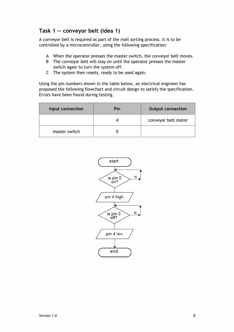
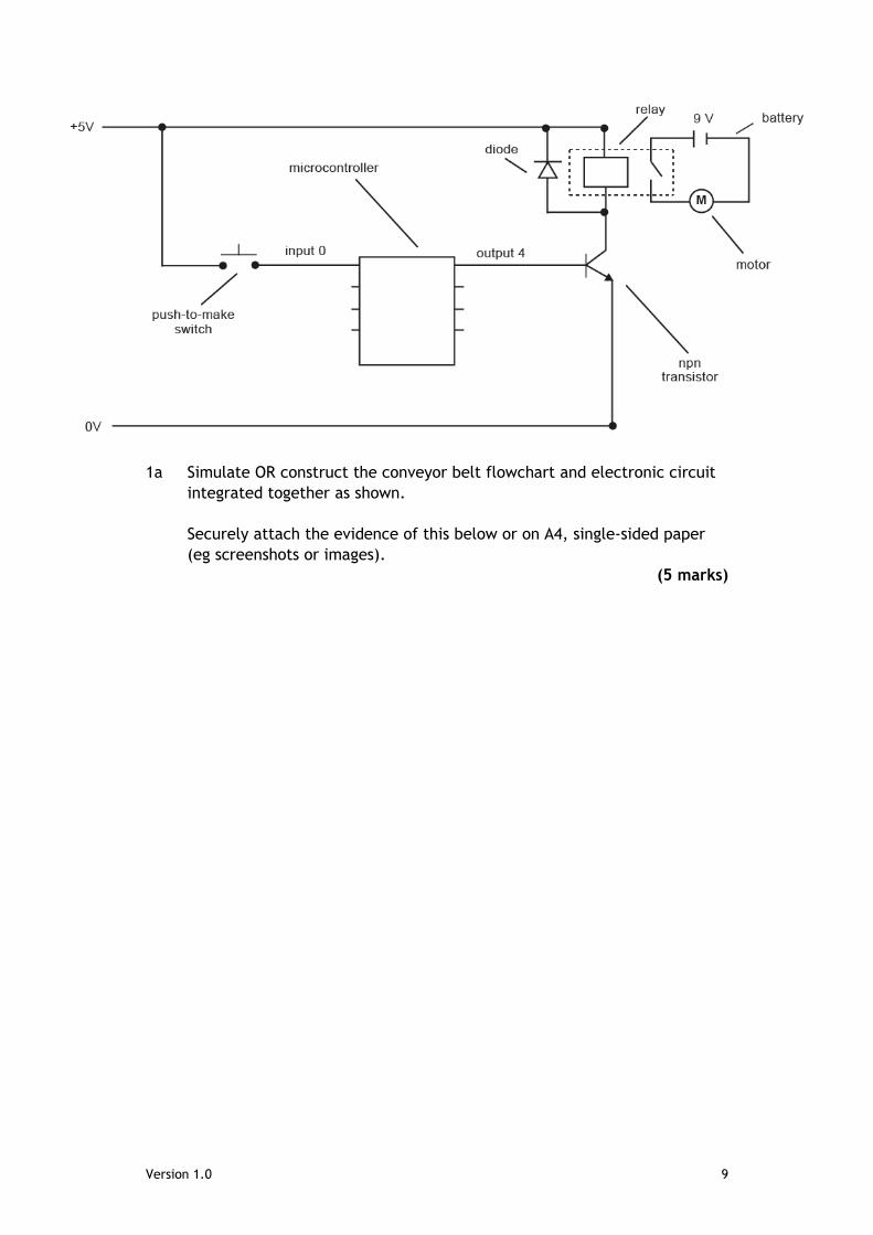
Task 1 — conveyor belt (idea 1)
A conveyor belt is required as part of the mail sorting process. It is to be
controlled by a microcontroller, using the following specification:
A When the operator presses the master switch, the conveyor belt moves.
B The conveyor belt will stay on until the operator presses the master
switch again to turn the system off.
C The system then resets, ready to be used again.
Using the pin numbers shown in the table below, an electrical engineer has
proposed the following flowchart and circuit design to satisfy the specification.
Errors have been found during testing.
Input connection Pin Output connection
4 conveyor belt motor
master switch 0
Version 1.0 9
1a Simulate OR construct the conveyor belt flowchart and electronic circuit
integrated together as shown.
Securely attach the evidence of this below or on A4, single-sided paper
(eg screenshots or images).
(5 marks)
Version 1.0 10
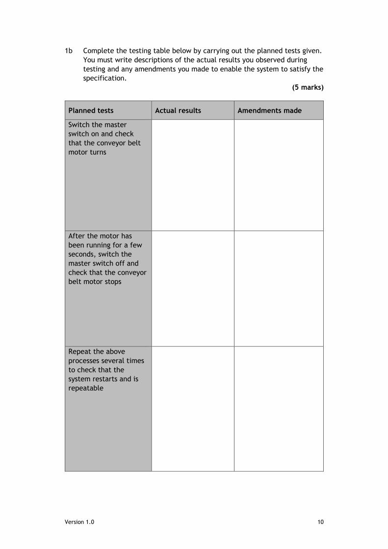
1b Complete the testing table below by carrying out the planned tests given.
You must write descriptions of the actual results you observed during
testing and any amendments you made to enable the system to satisfy the
specification.
(5 marks)
Planned tests Actual results Amendments made
Switch the master
switch on and check
that the conveyor belt
motor turns
After the motor has
been running for a few
seconds, switch the
master switch off and
check that the conveyor
belt motor stops
Repeat the above
processes several times
to check that the
system restarts and is
repeatable

Version 1.0 11
1c Based on your test results, amend your flowchart and/or electronic
circuit where necessary.
Securely attach the evidence of this below or on A4, single-sided paper
(eg screenshots or images), showing all your amendments.
(2 marks)

Version 1.0 12
1d Produce high-level microcontroller code to fully match the function
described in your amended flowchart shown in 1c.
Securely attach the evidence of this below or on A4, single-sided paper.
(1 mark)

Version 1.0 13
1e Evaluate your solution to task 1, by describing:
how well each specification point was met, referring to testing where
possible, and any amendments that had to be made
the overall effectiveness of your amended conveyor belt (idea 1)
design, relative to the original proposal
Securely attach the evidence of this below or on A4, single-sided paper.
(4 marks)
Version 1.0 14
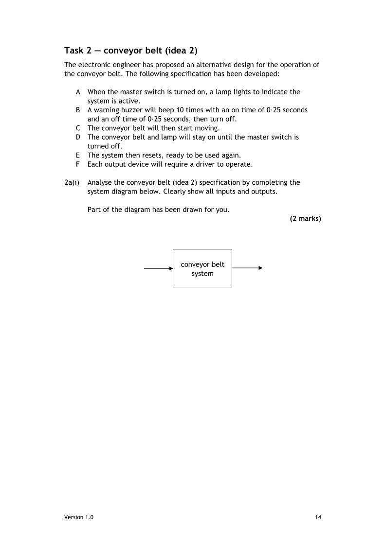
Task 2 — conveyor belt (idea 2)
The electronic engineer has proposed an alternative design for the operation of
the conveyor belt. The following specification has been developed:
A When the master switch is turned on, a lamp lights to indicate the
system is active.
B A warning buzzer will beep 10 times with an on time of 0·25 seconds
and an off time of 0·25 seconds, then turn off.
C The conveyor belt will then start moving.
D The conveyor belt and lamp will stay on until the master switch is
turned off.
E The system then resets, ready to be used again.
F Each output device will require a driver to operate.
2a(i) Analyse the conveyor belt (idea 2) specification by completing the
system diagram below. Clearly show all inputs and outputs.
Part of the diagram has been drawn for you.
(2 marks)
conveyor belt
system

Version 1.0 15
2a(ii) Fully analyse the conveyor belt (idea 2) specification by completing the
sub-system diagram below. Clearly show all sub-systems, the system
boundary, and interactions between sub-systems.
Part of the diagram has been drawn for you.
(4 marks)
microcontroller master switch
Version 1.0 16
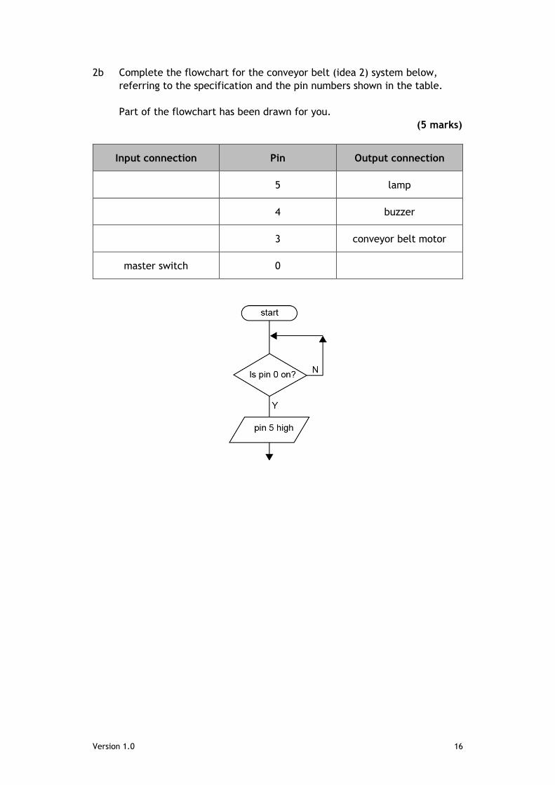
2b Complete the flowchart for the conveyor belt (idea 2) system below,
referring to the specification and the pin numbers shown in the table.
Part of the flowchart has been drawn for you.
(5 marks)
Input connection Pin Output connection
5 lamp
4 buzzer
3 conveyor belt motor
master switch 0
Version 1.0 17
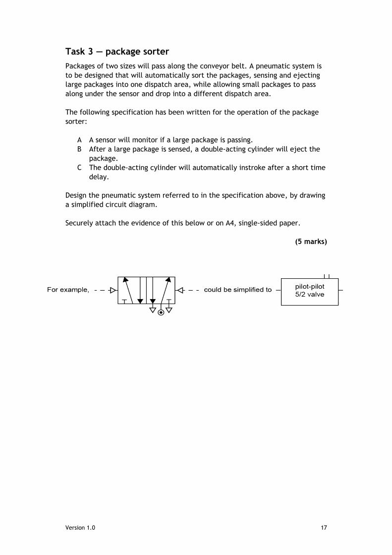
Task 3 — package sorter
Packages of two sizes will pass along the conveyor belt. A pneumatic system is
to be designed that will automatically sort the packages, sensing and ejecting
large packages into one dispatch area, while allowing small packages to pass
along under the sensor and drop into a different dispatch area.
The following specification has been written for the operation of the package
sorter:
A A sensor will monitor if a large package is passing.
B After a large package is sensed, a double-acting cylinder will eject the
package.
C The double-acting cylinder will automatically instroke after a short time
delay.
Design the pneumatic system referred to in the specification above, by drawing
a simplified circuit diagram.
Securely attach the evidence of this below or on A4, single-sided paper.
(5 marks)
Version 1.0 18
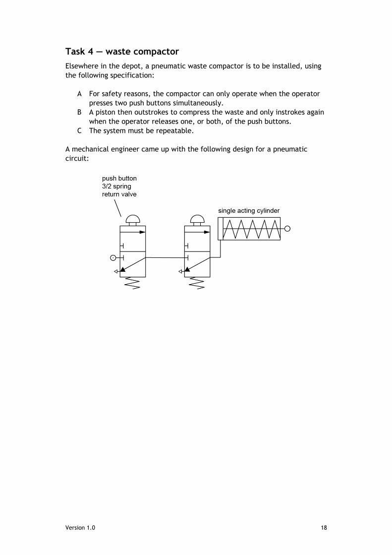
Task 4 — waste compactor
Elsewhere in the depot, a pneumatic waste compactor is to be installed, using
the following specification:
A For safety reasons, the compactor can only operate when the operator
presses two push buttons simultaneously.
B A piston then outstrokes to compress the waste and only instrokes again
when the operator releases one, or both, of the push buttons.
C The system must be repeatable.
A mechanical engineer came up with the following design for a pneumatic
circuit:
Version 1.0 19
4a Write a test plan for the waste compactor system. Describe four tests
that could be carried out in order to test that the system operates as
planned. Describe what you will test and how it will be tested.
Once you have simulated or constructed the pneumatic circuit, you can
complete the table with the actual results that you observed, including
any amendments that you had to make as a result of testing.
Securely attach the evidence of this below or on A4, single-sided paper.
(4 marks)
Planned tests Actual results Amendments made

Version 1.0 20
4b Simulate OR construct the waste compactor pneumatic circuit shown.
Securely attach the evidence of this below or on A4, single-sided paper
(eg screenshots or images).
(3 marks)

Version 1.0 21
4c Evaluate your solution to task 4 by describing how well it satisfies the
original specification, referring to testing where possible.
Securely attach the evidence of this below or on A4, single-sided paper.
(3 marks)
4d Describe and justify improvements that could be made to the operation of
the waste compactor system.
Securely attach the evidence of this below or on A4, single-sided paper.
(2 marks)
Version 1.0 22
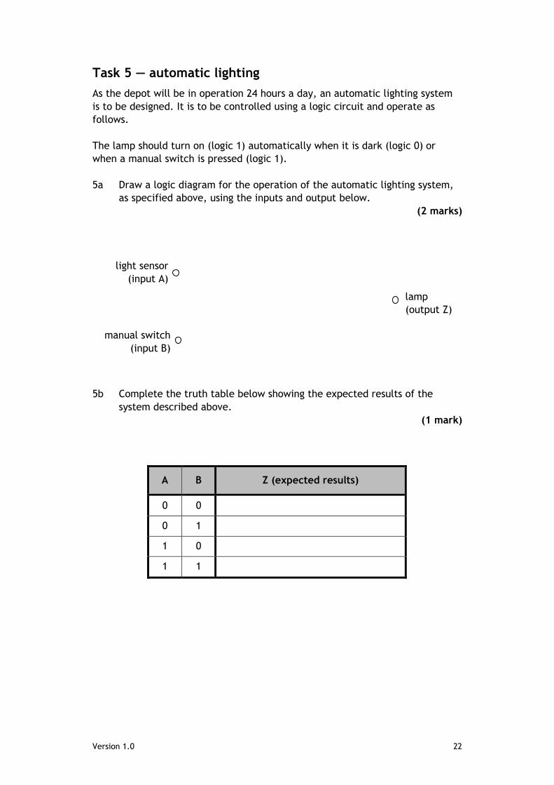
Task 5 — automatic lighting
As the depot will be in operation 24 hours a day, an automatic lighting system
is to be designed. It is to be controlled using a logic circuit and operate as
follows.
The lamp should turn on (logic 1) automatically when it is dark (logic 0) or
when a manual switch is pressed (logic 1).
5a Draw a logic diagram for the operation of the automatic lighting system,
as specified above, using the inputs and output below.
(2 marks)
5b Complete the truth table below showing the expected results of the
system described above.
(1 mark)
A B Z (expected results)
0 0
0 1
1 0
1 1
lamp
(output Z)
light sensor
(input A)
manual switch
(input B)
Version 1.0 23
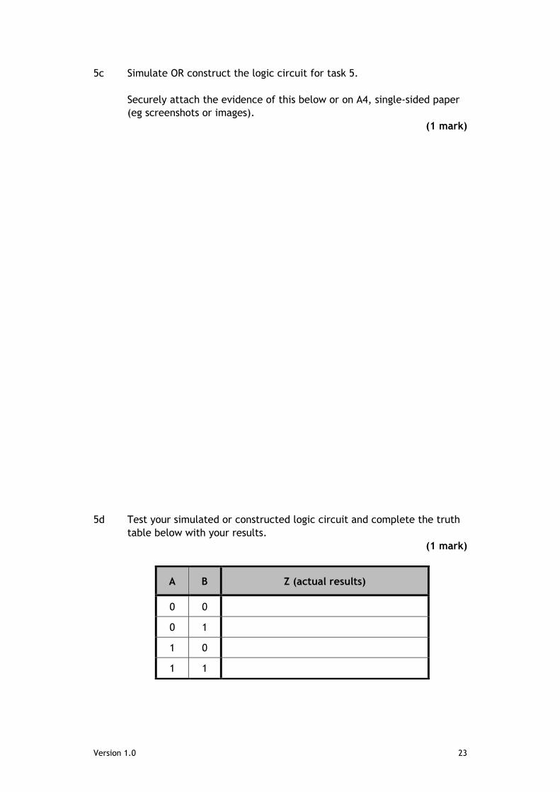
5c Simulate OR construct the logic circuit for task 5.
Securely attach the evidence of this below or on A4, single-sided paper
(eg screenshots or images).
(1 mark)
5d Test your simulated or constructed logic circuit and complete the truth
table below with your results.
(1 mark)
A B Z (actual results)
0 0
0 1
1 0
1 1
Version 1.0 24
Marking instructions Marking instructions are provided for this specimen assessment task. In line
with SQA’s normal practice, they are addressed to the marker. They will also
be helpful for those preparing candidates for course assessment.
Marking instructions will not be provided with annual assessment tasks, as
candidate evidence will be submitted to SQA for external marking. They will be
provided to markers and then published on the SQA website after marking is
complete.
General marking principles This information is provided to help you understand the general principles that
must be applied when marking candidate responses in this assignment. These
principles must be read in conjunction with the detailed/specific marking
instructions, which identify the key features required in candidate responses.
a Marks for each candidate response must always be assigned in line with
these general marking principles and the specific marking instructions
for this assessment.
b Marking should always be positive. This means that, for each candidate
response, marks are accumulated for the demonstration of relevant
skills, knowledge and understanding: they are not deducted from a
maximum on the basis of errors or omissions.
c If a specific candidate response is not covered by either the general
marking principles or detailed marking instructions, you must seek
guidance from your team leader.
Version 1.0 25
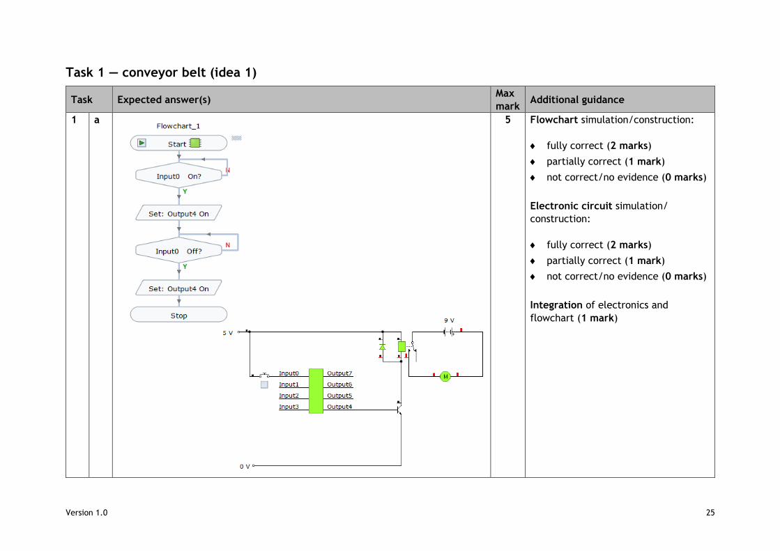
Task 1 — conveyor belt (idea 1)
Task Expected answer(s) Max
mark Additional guidance
1 a 5 Flowchart simulation/construction:
fully correct (2 marks)
partially correct (1 mark)
not correct/no evidence (0 marks)
Electronic circuit simulation/
construction:
fully correct (2 marks)
partially correct (1 mark)
not correct/no evidence (0 marks)
Integration of electronics and
flowchart (1 mark)
Version 1.0 26
Task Expected answer(s) Max
mark Additional guidance
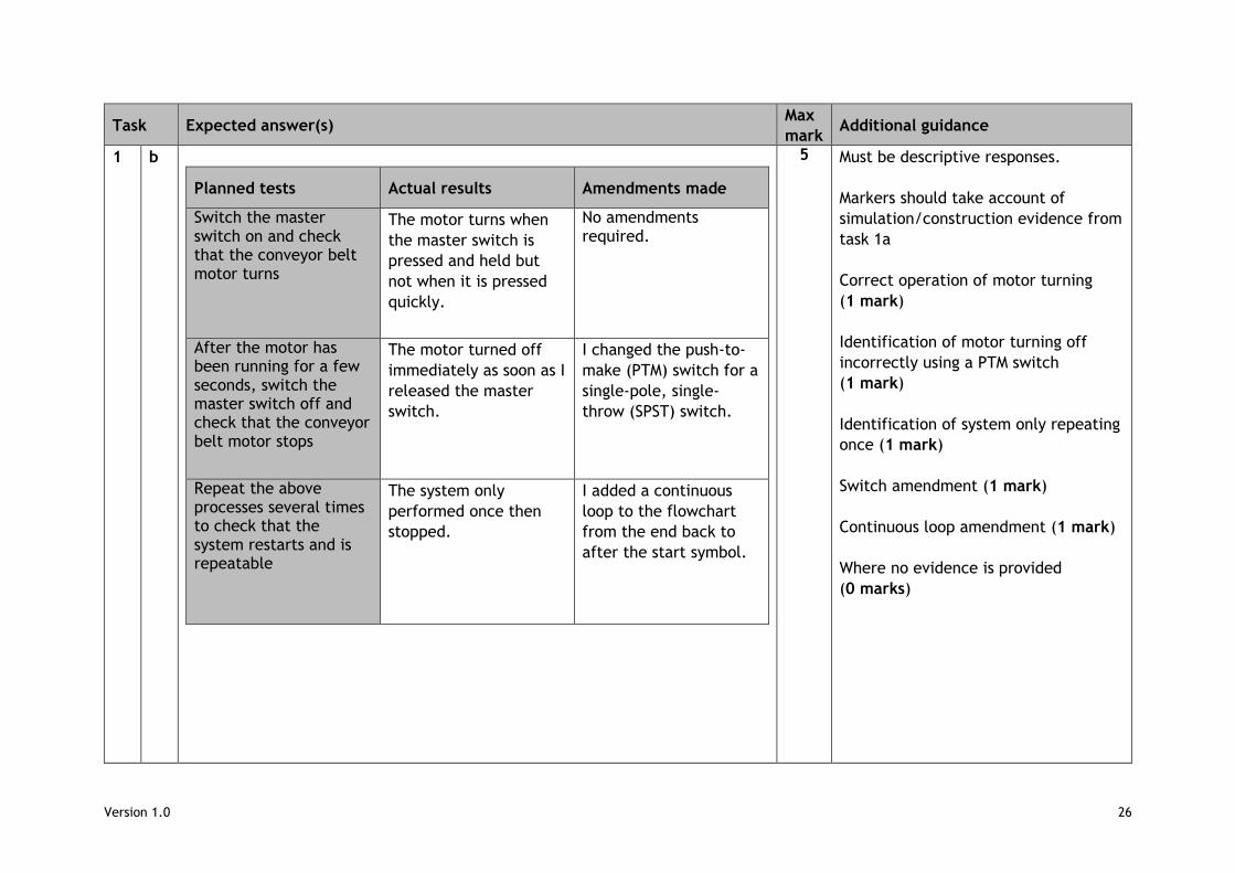
1 b
Planned tests Actual results Amendments made
Switch the master switch on and check that the conveyor belt motor turns
The motor turns when
the master switch is
pressed and held but
not when it is pressed
quickly.
No amendments required.
After the motor has been running for a few seconds, switch the master switch off and check that the conveyor belt motor stops
The motor turned off
immediately as soon as I
released the master
switch.
I changed the push-to-
make (PTM) switch for a
single-pole, single-
throw (SPST) switch.
Repeat the above processes several times to check that the system restarts and is repeatable
The system only
performed once then
stopped.
I added a continuous
loop to the flowchart
from the end back to
after the start symbol.
5 Must be descriptive responses.
Markers should take account of
simulation/construction evidence from
task 1a
Correct operation of motor turning
(1 mark)
Identification of motor turning off
incorrectly using a PTM switch
(1 mark)
Identification of system only repeating
once (1 mark)
Switch amendment (1 mark)
Continuous loop amendment (1 mark)
Where no evidence is provided
(0 marks)
Version 1.0 27
Task Expected answer(s) Max
mark Additional guidance
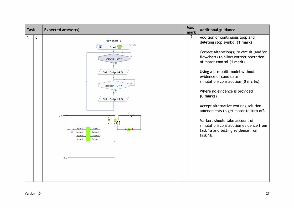
1 c
2 Addition of continuous loop and
deleting stop symbol (1 mark)
Correct alteration(s) to circuit (and/or
flowchart) to allow correct operation
of motor control (1 mark)
Using a pre-built model without
evidence of candidate
simulation/construction (0 marks)
Where no evidence is provided
(0 marks)
Accept alternative working solution
amendments to get motor to turn off.
Markers should take account of
simulation/construction evidence from
task 1a and testing evidence from
task 1b.

Version 1.0 28
Task Expected answer(s) Max
mark Additional guidance
1 d 1 Correct code to fully match the
flowchart in task 1c (1 mark)
Where no evidence is provided
(0 marks)
Accept manually written or
automatically generated.
Version 1.0 29
Task Expected answer(s) Max
mark Additional guidance
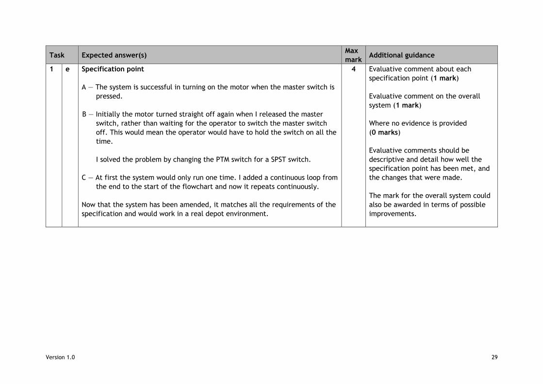
1 e Specification point
A — The system is successful in turning on the motor when the master switch is
pressed.
B — Initially the motor turned straight off again when I released the master
switch, rather than waiting for the operator to switch the master switch
off. This would mean the operator would have to hold the switch on all the
time.
I solved the problem by changing the PTM switch for a SPST switch.
C — At first the system would only run one time. I added a continuous loop from
the end to the start of the flowchart and now it repeats continuously.
Now that the system has been amended, it matches all the requirements of the
specification and would work in a real depot environment.
4 Evaluative comment about each
specification point (1 mark)
Evaluative comment on the overall
system (1 mark)
Where no evidence is provided
(0 marks)
Evaluative comments should be
descriptive and detail how well the
specification point has been met, and
the changes that were made.
The mark for the overall system could
also be awarded in terms of possible
improvements.
Version 1.0 30
Task 2 — conveyor belt (idea 2)
Task Expected answer(s) Max mark
Additional guidance
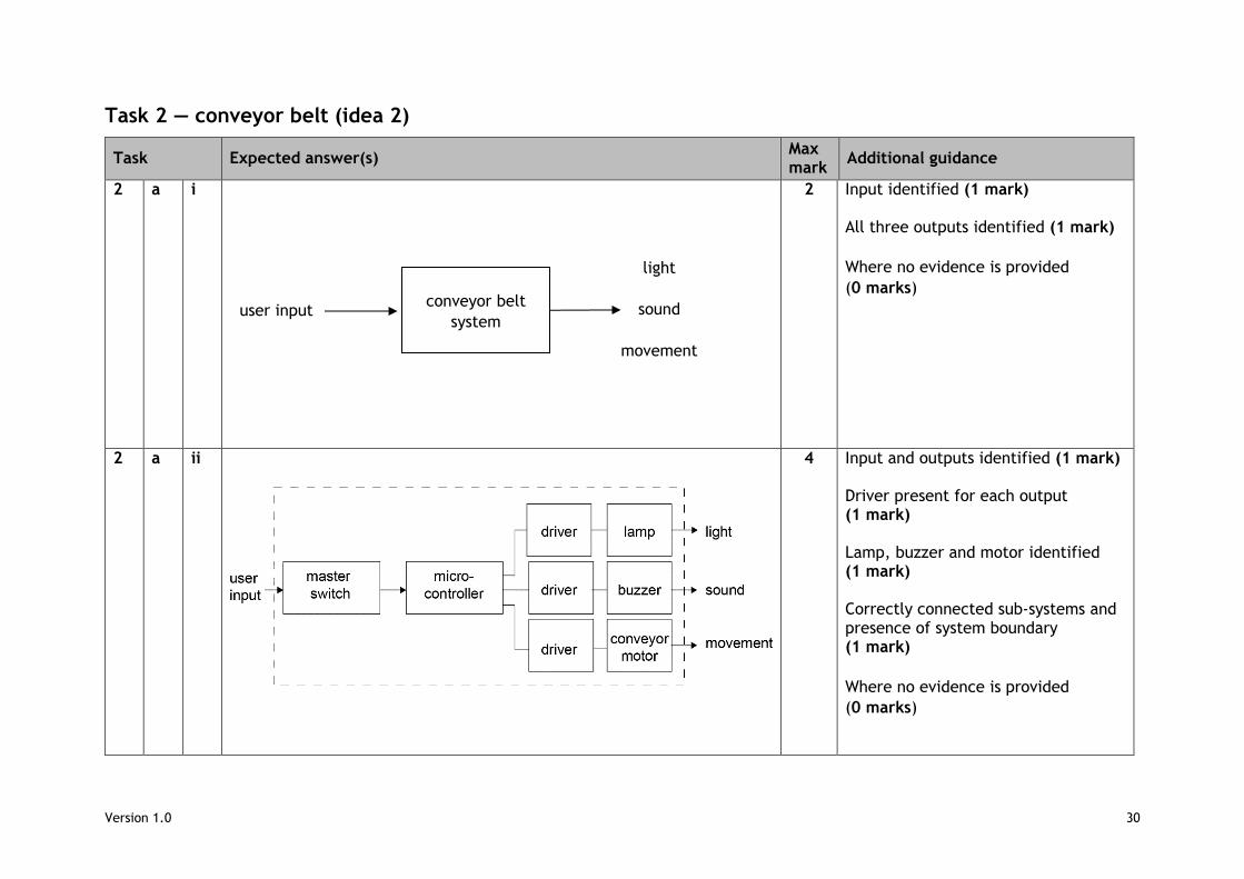
2 a i
2 Input identified (1 mark) All three outputs identified (1 mark)
Where no evidence is provided
(0 marks)
2 a ii
4 Input and outputs identified (1 mark) Driver present for each output (1 mark) Lamp, buzzer and motor identified (1 mark) Correctly connected sub-systems and presence of system boundary (1 mark)
Where no evidence is provided
(0 marks)
conveyor belt
system user input
light
sound
movement
Version 1.0 31
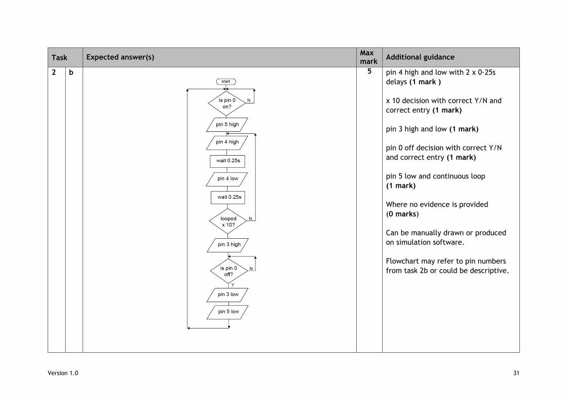
Task Expected answer(s) Max mark
Additional guidance
2 b 5 pin 4 high and low with 2 x 0·25s
delays (1 mark )
x 10 decision with correct Y/N and
correct entry (1 mark)
pin 3 high and low (1 mark)
pin 0 off decision with correct Y/N
and correct entry (1 mark)
pin 5 low and continuous loop
(1 mark)
Where no evidence is provided
(0 marks)
Can be manually drawn or produced
on simulation software.
Flowchart may refer to pin numbers
from task 2b or could be descriptive.
Version 1.0 32
Task 3 — package sorter
Task Expected answer(s) Max mark
Additional guidance
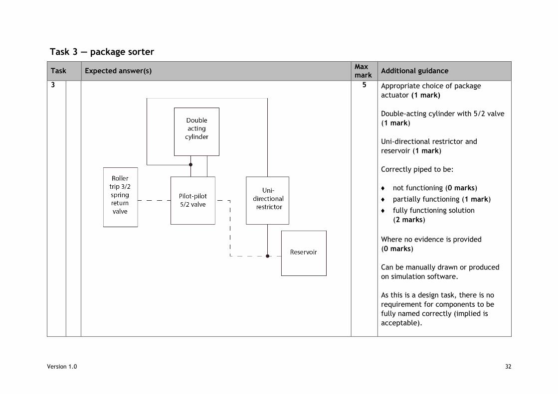
3
5 Appropriate choice of package
actuator (1 mark)
Double-acting cylinder with 5/2 valve
(1 mark)
Uni-directional restrictor and
reservoir (1 mark)
Correctly piped to be:
not functioning (0 marks)
partially functioning (1 mark)
fully functioning solution
(2 marks)
Where no evidence is provided
(0 marks)
Can be manually drawn or produced
on simulation software.
As this is a design task, there is no
requirement for components to be
fully named correctly (implied is
acceptable).
Version 1.0 33
Task Expected answer(s) Max mark
Additional guidance
Candidates may choose to produce as
a block diagram, a circuit diagram or
as a hybrid (all are acceptable).
No marks are available for naming line
types or producing accurate port to
port piping.
Version 1.0 34
Task 4 — waste compactor
Task Expected answer(s) Max mark
Additional guidance
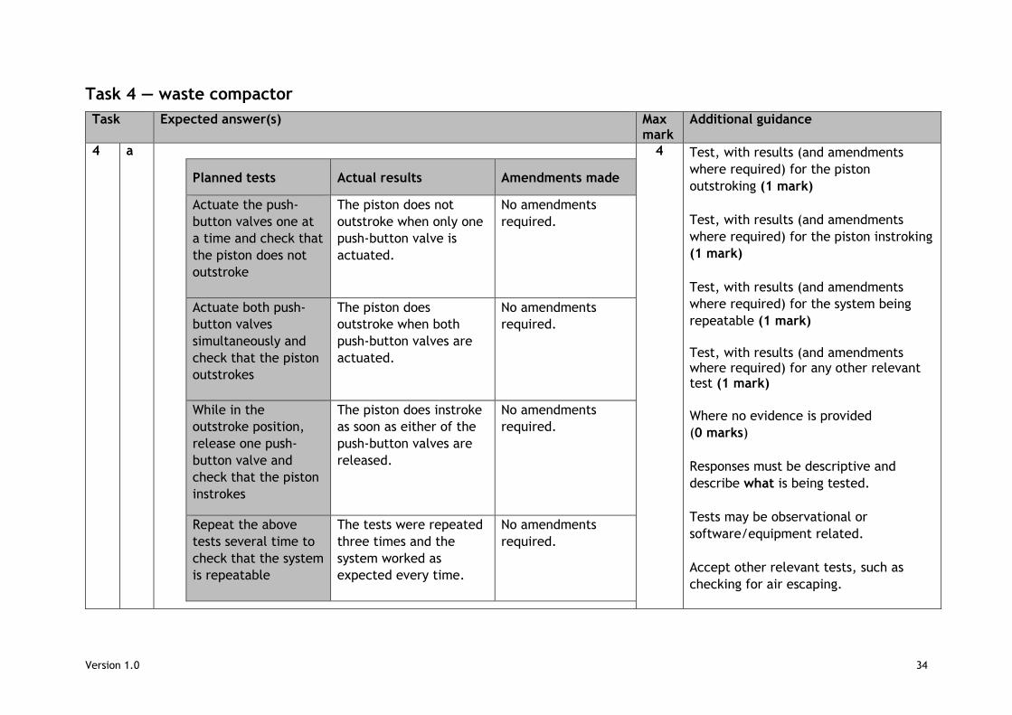
4 a
Planned tests Actual results Amendments made
Actuate the push-
button valves one at
a time and check that
the piston does not
outstroke
The piston does not
outstroke when only one
push-button valve is
actuated.
No amendments
required.
Actuate both push-
button valves
simultaneously and
check that the piston
outstrokes
The piston does
outstroke when both
push-button valves are
actuated.
No amendments
required.
While in the
outstroke position,
release one push-
button valve and
check that the piston
instrokes
The piston does instroke
as soon as either of the
push-button valves are
released.
No amendments
required.
Repeat the above
tests several time to
check that the system
is repeatable
The tests were repeated
three times and the
system worked as
expected every time.
No amendments
required.
4 Test, with results (and amendments
where required) for the piston
outstroking (1 mark)
Test, with results (and amendments
where required) for the piston instroking
(1 mark)
Test, with results (and amendments
where required) for the system being
repeatable (1 mark)
Test, with results (and amendments where required) for any other relevant test (1 mark)
Where no evidence is provided
(0 marks)
Responses must be descriptive and
describe what is being tested.
Tests may be observational or
software/equipment related.
Accept other relevant tests, such as
checking for air escaping.
Version 1.0 35
Task Expected answer(s) Max mark
Additional guidance
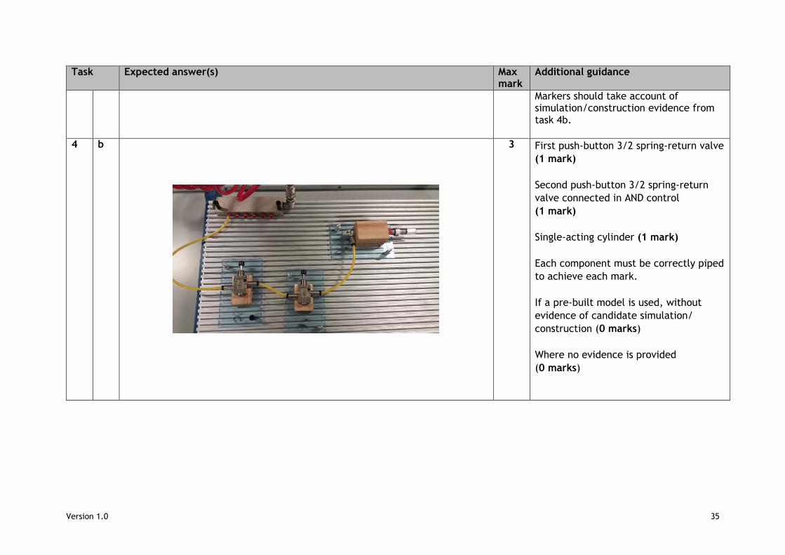
Markers should take account of simulation/construction evidence from task 4b.
4 b 3 First push-button 3/2 spring-return valve
(1 mark)
Second push-button 3/2 spring-return
valve connected in AND control
(1 mark)
Single-acting cylinder (1 mark)
Each component must be correctly piped
to achieve each mark.
If a pre-built model is used, without
evidence of candidate simulation/
construction (0 marks)
Where no evidence is provided
(0 marks)
Version 1.0 36
Task Expected answer(s) Max mark
Additional guidance
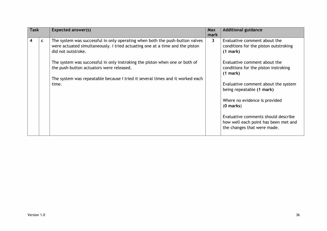
4 c The system was successful in only operating when both the push-button valves
were actuated simultaneously. I tried actuating one at a time and the piston
did not outstroke.
The system was successful in only instroking the piston when one or both of
the push-button actuators were released.
The system was repeatable because I tried it several times and it worked each
time.
3 Evaluative comment about the
conditions for the piston outstroking
(1 mark)
Evaluative comment about the
conditions for the piston instroking
(1 mark)
Evaluative comment about the system
being repeatable (1 mark)
Where no evidence is provided
(0 marks)
Evaluative comments should describe
how well each point has been met and
the changes that were made.
Version 1.0 37
Task Expected answer(s) Max mark
Additional guidance
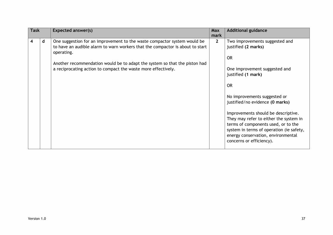
4 d One suggestion for an improvement to the waste compactor system would be
to have an audible alarm to warn workers that the compactor is about to start
operating.
Another recommendation would be to adapt the system so that the piston had
a reciprocating action to compact the waste more effectively.
2 Two improvements suggested and
justified (2 marks)
OR
One improvement suggested and
justified (1 mark)
OR
No improvements suggested or
justified/no evidence (0 marks)
Improvements should be descriptive.
They may refer to either the system in
terms of components used, or to the
system in terms of operation (ie safety,
energy conservation, environmental
concerns or efficiency).
Version 1.0 38
Task 5 — automatic lighting
Task Expected answer(s) Max mark
Additional guidance
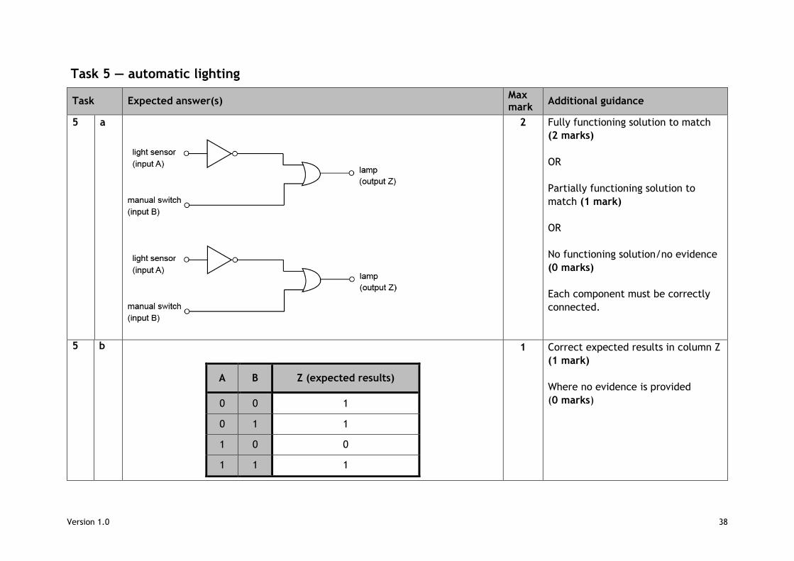
5 a
2 Fully functioning solution to match
(2 marks)
OR
Partially functioning solution to
match (1 mark)
OR
No functioning solution/no evidence
(0 marks)
Each component must be correctly
connected.
5 b
A B Z (expected results)
0 0 1
0 1 1
1 0 0
1 1 1
1 Correct expected results in column Z
(1 mark)
Where no evidence is provided
(0 marks)
Version 1.0 39
Task Expected answer(s) Max mark
Additional guidance
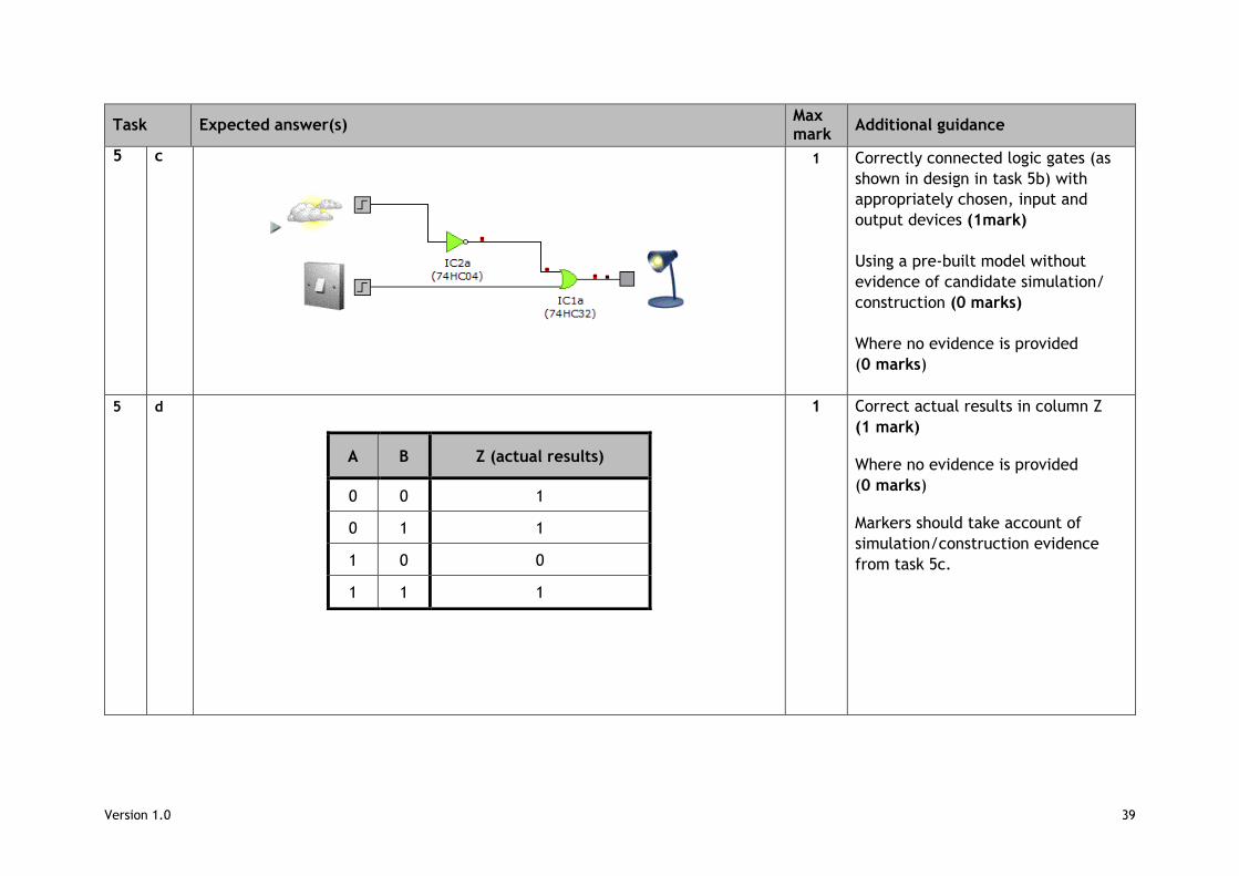
5 c
1 Correctly connected logic gates (as
shown in design in task 5b) with
appropriately chosen, input and
output devices (1mark)
Using a pre-built model without
evidence of candidate simulation/
construction (0 marks)
Where no evidence is provided
(0 marks)
5 d
A B Z (actual results)
0 0 1
0 1 1
1 0 0
1 1 1
1 Correct actual results in column Z
(1 mark)
Where no evidence is provided
(0 marks)
Markers should take account of
simulation/construction evidence
from task 5c.

Version 1.0 40
Copyright acknowledgements Page 7: box on conveyor roller. 3D Rendering — Shutterstock 514897444
Version 1.0 41
Administrative information
Published: August 2017 (version 1.0)
History of changes
Version Description of change Date
Security and confidentiality This document can be used by practitioners in SQA approved centres for the
assessment of National Courses and not for any other purpose.
Copyright This document may be reproduced in whole or in part for assessment purposes
provided that no profit is derived from reproduction and that, if reproduced in
part, the source is acknowledged. If it needs to be reproduced for any purpose
other than assessment, it is the centre’s responsibility to obtain copyright
clearance.
Re-use for alternative purposes without the necessary copyright clearance may
constitute copyright infringement.
© Scottish Qualifications Authority 2012, 2017