national advisory committee for aeronautics · condu cted at langley memo rial aerouautical ......
TRANSCRIPT

ARR No. 3G30
NATIONAL ADVISORY COMMITTEE FOR AERONAUTICS
ORIGINALLY ISSUED July 1943 as
Advance Restric t ed Repor t 3G30
'"
/
EFFECT OF TUREtJI.ENCE en AIR-FLOi-l ME.ASUREM:ENTS J
BEHlND ORIFICE PLATES
By Jack N. Nielsen
Langley Memorial Aeronautical Laboratory Langl ey Field, Va.
WASHINGTON
NACA WARTIME REPORTS are reprints of papers originally issued to provide rapid distribution of advance research results to an authorized group requiring them for the war effort. They were previously held under a security status but are now unclassified. Some of these reports were not technically edited. All ha e been reproduced without change in order to expedite general distribution.
L - 274
https://ntrs.nasa.gov/search.jsp?R=19930093613 2018-09-01T08:08:11+00:00Z

---
Date Loaned
C t No 1138 Library Bu reau a . .

NATIONAL ADVISORY COMMITTEE FO! AERONAUTICS
ADVANCE RESTRICTED REPORT
EF1ECT OF TURBULENCE ON AIR- FLOW MEASUREMEN~S
BEHIND ORIFICE PLATES
By Jack N. Niels en
SUMMARY
Determinations of "a ir-flow quantity have been made in front of aId behind th r ee o r ifice plates to determine the errors introduced i n the quantity measurements by the turbule n ce behind the orifice pla tes . For the orific~ plates tested, t he results showed that th e measurements must be taken 40 to 60 ho le d:ameters downstrea~ from the plates to insure accurLcy . A te udency for the indicated s tat ic p ressure to r ise du r ing the decay of the turbulence was fo und . In all c a se s , the indicated total eressure dropp ed duri~g t he d ec ay of turbulence .
I N':!.'- ODUCTIOI~
Orifice p l ates h ave come into g eneral use for simUla ti ng radiator s Bnd other res istance elements in studies of ai r flow i n cooli & du~ts . Althou~b orifice p lates hav e t~e advantag e of muc h l e ss scsle effect than screens used for t his pur-pose , the larg e-scale turb'llence th8t they introduce i nterferes witl1 ti.le ,,,eas'"'..re ruen"Ls of '7E;10cit J' and ';> r e s su r e los s w h e :l the s e lli e a S"C. r e;-o e I t 6 mu s t -:J e r.: a dec los e behind th e elate . rna u u r o s ~ of the present invostigati on condu cted at Lan g ley Memo rial Aerouautical Labor atory was to determine t he va ri at io n of the ruagnitudes of tne error s i1 the measu rem ents of velocity and pressure loss with d i st an c e of the measuri! G' tubes b0hind tl ~ orifice p late.
SYM:aOL S
Qo air-fl ow quanti t y measu r ed i~ front of orifice plate
Q. air-flow quantity me asu r ed behind orifice plat e ~

2
go dynamie p ressu r e at i t ation upst r eam of orifice pl a ta
Po st a tic p res su re at station upstream of orifice plate
Ho tota l pressu re at , u p stream face of orifice p l ate
Pi indicated static p ressure a t st ation behind orifice plate
Hi ind ic ated t ota l pr essure at station behind orifice plate
APPARATUS AND ME1HODS
The duct s yst em us ed i n the tests is shown dia g rammat ic a lly in fi gure 1 . It consisted of a unifo r m rectangu lar test section of s hee t me t a l , with a lar g e woode. bel l at the i n let and an ex? andins passage at the,outlet leadi ng to a variable-speed b lo we r. The velocity of the entering a ir fl ow was measured by means of a net Rork of static - p ressure and tota l- pressu re tube s p laced in the throat of t Ol e bell ( fit, . 2) . .A. Bi f."l ilf:l.'l' n etwo rk of tube s (fi g . 3 ) was used for the downs t r e a m me asurements , whi ch
,were mad e at t h r ee diffe r ent distan c es f r om the or i f i ce plate : gi, 20L an d 27i iilches , as indicat e d i n figu r e 1-The airspeed was ab o~ t 67 feet pe r second for all tests. All pre ssures were r e corded s i mu ltaneously by means of a 1 00 - tub~ photo ~ raph ic manometer.
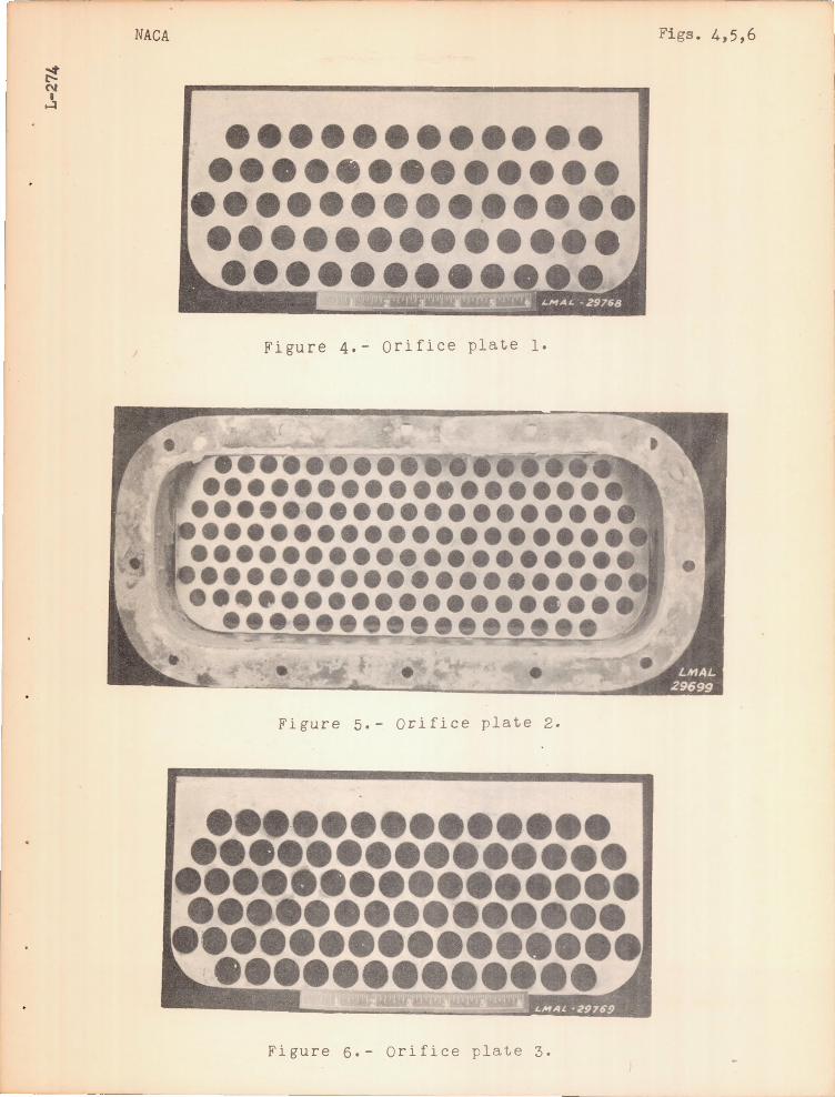
The thr ee orifice ~ l ates tested , wh i ch a r e des i gnated or i f ice p 1 ate s 1, 2 , and 3 (f i g s . 4 , 5 , and 6), w e r e rna d e of ts-inch steel p l ate , 'wit h punched ~ -i .L1Ch or ~ -inch ho le~. No effort was made to r ound oIf the edges formed by the pun ch . These edges faced upst r eam fo r orifice plates 1 and 2 and do wn strea m for orifice plate 3 . The direction in wh i c h the e dg es faced, howeve r, p r oduced no app r e ciabl e effec t on t he p r essure - d r op coefficient , ac cording to r eference 1 . Orifice p la te 3 h ad a desi~n pressur edrop coeffi c ient of 2 . 6 (r ef ere nc e 1) . Th e ot her two plates had design pressu r e- d r op c oefficients of abo~ t 6 .0 but differed i n h o l e diameter . The cha racteristics of the three ori f ice e l at es are sUIDGari zed in the f ollowing tabl e:

3
.--.,, ' , .....:....~ .-r" -•. ~.!-' ' •• -.., .... _ • ..-.-~.-:~ ... ~-:. , __ _
"" '~ ' ... : .. : Ra-tr'O 'Of~ . . .• , .' I Desigri p"re ssure-di- 'i,f.ic e op~n a'rea" tr ole drop coefficient ·," yea. ·sured . ~~at ~ . ~o : fron .t~. l . di~~eter (f::om fig: . 7 ' of pr 'es 'sure-drop
,.".- .. . .. , are& ."".' (1~1.) relerence :l) .. c.oefficient
_ .t. ~ , .. ~ . ' ",' .:-" - - ' ,
~~ . . , . .1 .... ,.0 ,391 3 /4 .. 6.3 '" 6~8 . I .' . l
.:~ I .., ~ , . . ' 40'2 1/2,' 6 • 0 . 5. 9 H . ;3 " I . 540 3 I 4 2 • 6 , .' 2 • 0
-" "
- - •. ;r----L- -------.-- --.:-. ________ .. _~ ____ ~ _____________ .~ _______ _
"
" , .
",: ': '
, RESU LTS ' lN'D . DI.SCUSSION ,I ',.
'. ":' 1' \ 'i~?ur 'e : 7 .the :r 'atio of tne <'!ir-flow quan~ity ·i 1ldi c·!3.t·e.d. by t 'he m.ea:s·urernen ts behind the orifice plate to th~: ;~ue air-flow quantity lnd~cated by the measure ments in ' f ro ni of the orifice pla~~ Qi/Qo is plotted a g ainst a.i~t~nce 'b e r,ind the orlf~ce ,?late. Sim'ole a.rithmetic ave r age s of ·t he ind icat ed velociti·es wfl~e u·sed. in COCl'pu tj:j,1'g .. thes,e air- f'low ' quan'titi.e·s . . With orifice plat.e I, w.h.ic)J., had t:le hI b'h est ·pr,essur.e clrop, ' Q-i wa s 16 percent
. t~o;o(' hig-h : when ' measu red~·g~. i 'n c:te s 'behind the pI'ate and 5 'Oer'cent too high at 27i Inches be ind the ~late. With orifice plate 3. whi c~ had the lowest ~ ~~ssuredrop, Qi was : tob . hi ~ l! 'by 7..p,e l';C eEt a :ld 2:5 " pe~cent , respec~ivel;y, at ~thsso two stat~o ns . It 1~ lIkely that at least part ~f ·· the error 'at the downstream station i .$ due · to tha absS~o e cif ' rrea~u~ini tubes ' i~ ' the low-velocity 'bouridary l aye 'r al'ong' the '\"1.al1. -Thi;s" error did not exist in the measurement' or' QQ ' 'be c ause the boundary layer at the b ell th ro at was ' very thin_
I tap pea r s, t 1:;. en, . t ~1 a. t :: 0 r 0 r i fie e pIa t e 6 0 f the t y p e i nv esti g ated . a~r-f1ow quantities measured be h ind the plate will be considerably too high unle&s ·t he· measuring tubes are b~twee~ 40 ' ~nd 60 ho~e dia met e rs downstream from t h~e p Ia t e" . T ~1 i S 1 eng t h b ':f'" d u .c· t · \7 i 11 h c. r d 1 ~ be a v ail a'b 1 e I
, hQw&~er, uhle~~ ~he orifices are sm~ller than those used in ' thBS~' t,·ests. , Fo .r , example ', if scale effect is negligible , i-inch orifibes wo~id be ~atisfactory in a full-scale simu la ted ethylene- ~l;rc ol " rad :i.'at'or d.uct .. Fo_ ~his case, tbe ori fice ·'Olci.te would 'be ·Diacea.' ~he're the front face of the rattiator- Wd\lld --be. a nd. tlle ' me'a.su.rinr;· tubes would' 'be p_l;:lced 10 or 12 inches fa r the r back ~ where the rear face would 'be .
In fi gures 8, 9, and 10 t~e pressure-drop coefficients . as determined from the readings of both the static-pressure

~--
4
tubes a.nd the tot a l-pressure tubes, are plotted against dist ance behind the orifice plate. Behind orifice plates l an d 2p the measured static pressure Pi tends to in-
crease along the passage; the pressure drop determined from the static-pressure measurements correspondingly decreases. At least part of this static-pressure rise is due to a transformation of a portion of the random kin e ti c energy to static pressure during the decay of the turbulence.
~he measured total pressur~ Hi decreases alon g the pass age, and the pressure drop determined from the totalpressure measurements correspondingly increases c Here, again, part of the effect is due to the decay of the turbulence. The decrease in the measured total pressure is due to the following factors: First. the readings of a total-pressure tube in a turbulent flow are increased by a dynamic pressure based on the mean square of the turbule n t velocities (reference 2); and, second, this dynamic pre ssure is not entirely recovere d as total pressure during the decay of the turbulence. The two types of pressuredrop determination nearly agree where the error in the measurement of the air-flow quantity becomes small - that is, at 40 to 60 hole diameters downstream from the orifice plate.
It will be noted t~at the relative errors in the pressure-drop determination were, et least for orifice plates 1 and 2, less than the errors in the determination of the air-flow quantity. Thus, the ma x imum difference of the pressure-drop coefficients measured behind the orifice plate is only about 5 percent of their mean value in figures 8 and 9 and about 8 percent in figure 10.
CONCLUSIONS
1. Measured air-flow quantities may be 10 to 15 percent too high if the measuring tubes are 15 to 20 hole diameters behind an orifice plate. A distance of 40 to 60 hole diameters must be used for accuracy.
2. Pressure drops as determined from total-pressuretube readings increase with distance of the tubes from the orifice plate; pressure drops as determined from staticpressure-tube readings tend to decrease with distance of the tubes from the orifice plate. For the orifice plates

..
c._t
-.::t t-
5
tasted, the two p re~5ure drops become nearly equal at 40 to 60 hole diaceter~ behind the plate. where the intensity of the turbulence in the air flow is greatly decreased.
~ LaDgley Memorial Aer~nautical Laboratory, H Nationa l AdvisQt'y Committee for Aeronautics,
Langley Fiold, Va.
REFERENCES
l . Czarnecki, K. R,; Pressure·-Drop Characteristics of Orifice Plates Used to Simulate Radiators. NACA A.R.R.) March 19~2.
G . Goldstein, S.: A Note on the Measurement of Total Read and static Pressure in B Turbulent stream. Proc. Roy. Soc. (London) , ser. AI vol. 155\ no. 886, July 1, 1936, pp. 570· ·575.

Pressure tubes i n inlet measuring a ir quantity
Downstrea~rr pressure t ubes
~~ t Station
~~f 1 2 3
\ i i ' " ~ir Bell entrance r" -·t~-9-3/ 4"~r-- ll" '";< 7" -., ~"14"
" -------- t ~~ Orifice plate
Figure 1.- ScneDatic diagram of test secti on.
L-2 ,{,4
to bla:wei! =-
~ ~
~j
t-'. rr,~
I-'
----- --------~

- .1-.- . J ('-(\/ I
I-=l
NACA Figs. 2,3
--/' 0 /
0
f 0 ® \ I @ I
0 0
0 0 ® 0 0 ® 0 ®
i ~ I 0 0 0 o 0 0 0 0\
i 0
\ ®
o o o o \.. 0 ...... '- -----------------~ -(?, Stati c pressure () Total pressure
Fiplre 2.- Upstream nct'lIor~>;: of static-pr0ssur0 ani total-pressure tubes.
r---::==_~-======_==::_ l~" ___ ~==-==---=--=~= , !//_. @O 00 @O .~ ( 00 00 00 I ! ®O 090 @O
Q90 ®O 00 I O(??J 00 0 (2) 0 ®O@000®O®O®0 5.2"
® 0 rglO 00
.1 ,~ O ) !
/ I
-.---------.~-q- -----~--.--~-
0 ()
@ 0
<9 0
Q() ()
'8 0 (8': r,
\..1
00
~ static pres sure () total pres~~re·
Fit,"Uro 3 . - DoVil streac !:.et--ilorl':: of s t3. tic-~)rGs suru and total-prossure tubes.
NACA
e eeee e e ee
Figure 4.- orifice plate 1.
Figure 5.- orifice plate 2.
Figure 6.- Orifice plate 3.
Figs. 4,5,6

JlTACA l!'ig., '"I
,:--',\1
jj'i ;,ul'e 7 .- Error in flo v- qu.D.!1 ti t~ measur eme:lts downotream of orifice p l ate.

NAGA
r-----!-l---T---r---- c.\-=-t--==~ I ~ . -:~, ..
--~---r-~---1---r--r--r~~--I~-1
I
Figur e 8 . - Orifice- pl a te pressur e- drop coefficients as measu red by staticpressure and total-pressure tubes. Orifice plate 1.

NACA Fi f'. 9
--- --' ---l----r-----r---] --------- ---+------+--
---.- "- -- -~~l-i-~ -6.00 ---- -' - - . --. ---·-l --~··-~·- ·-· ·
~ -- ----+ -"t- -- - -- ----: 5 , 96 - - --T-- -~l-~ l' --l--+~- ---~ -- -+ ~~-l ,--+-~-l---,- ---- r-l-.--- - -- --+-----+-
~5 ' 92
1
_~_~J ___ 0 St~tic Ip_ .sLre tl---- -1----- -- - . ~
...... ----.- - ---' ,') Tot a l pr e ss~I'e - - - .-- . -.--I---~
'r --i-ir--'-+-- +
~ 5 , 6,; i~~ 1-- - f ----1- ---'-- -i-... -1---- --.-~ - --- -'-- -1 ---~ ---t- - -I ~ J-~ T -j --- "; ~- -~----- --~ --.---P-. I I I ' I I ---- . T'- - --.-. -r---1- -- -. ~ - -- - - - - --- -----
! I I ! 1/ I . I 5 , 7'1-- l--~t- ~I---i ~1- -- -- -t-~+~l- -
I - +- -t ~---I- -+----l~- ,t+r--+---+--+--+-------I 5 . 72 __ _ I --l--~ .. J--- i I I ) •
o .~ 8 12 16 20 24 28 Dis t nnc0 behind orifice pln t e ) in.
Fi gur 0 9 , - Orif i ce- pI n t o pr os surG-dr op coeff ici 0~ts a s mea su r ed by staticprossure and t otnl-pressur e tubes . Ori fice plate 2.
-- --

L
NACA .J!'lf· 10
Di stance bohind orifice plato~ in.
J]' igllr c 10 . - Or ifico- J;:)lu t e preGsm' G- .:ll' 0;9 0o ~,n:fic i o!.\t s as r~eD.sllred by s t n t i cpressur e n!1d tota l-press'..lTo tulH'Is. Orif i cG plate 3.
j