national advisory committee for aeronautics · i national advisory committee for aeronautics...
TRANSCRIPT
223181
NATIONAL ADVISORY COMMITTEE
FOR AERONAUTICS
TECHNICAL NOTE 2700
RECIPROCITY RELATIONS IN AERODYNAMICS
By Max. A. Heaslet and John R. Spreiter
Ames Aeronautical Laboratory Moffett Field, Calif.
Washington May 1952
REPRODUCED BY NATIONAL TECHNICAL INFORMATION SERVICE
U. S. DEPARTMENT OF COMMERCL SPRINGFIELD VA 22161
PRICES SUBJECT TO CHANGE
https://ntrs.nasa.gov/search.jsp?R=19930083234 2018-06-23T08:46:42+00:00Z
I NATIONAL ADVISORY COMMITTEE FOR AERONAUTICS
TECHNICAL NOTE 2700
RECIPROCITY RELATIONS IN AERODYNAMICS
By Max. A. Heaslet and John H. Spreiter
SUMMARY
Reverse-flow theorems in aerodynamics are shown to be based on the same general concepts involved in many reciprocity theorems in the physi-cal sciences. Reciprocal theorems for both steady and unsteady motion are found as a logical consequence of this approach. No restrictions on wing plan formor flight Mach number are made beyond those required in linearized compressible-flow analysis. A number of examples are listed, including general integral theorems for lifting, rolling, and pitching wings and for wings in nonuniform downwash fields. Correspondence is also established between the build-up of circulation with time of a wing starting impulsively from rest and the build-up of lift of the same wing moving in the reverse direction into a sharp-edged gust.
INTRODUCTI ON
Some of the most important results in the recent study of wing theory have been achieved through the development of reverse-flow rela-tions. The theorems already obtained are of outstanding practical util-ity and it appears obvious that the fullest exploitation ofthe methods has yet to be accomplished, either from a purely theoretical standpoint or in the routine calculation of wing characteristics. Attention to such problems in aerodynamics was initiated by von Karm.n (reference 1) who first announced the invariance of drag with forward and reversed direc-tions of flight for a nonlifting symmetrical wing at supersonic speed. Subsequently, advances in the theory were made by Munk, Hayes, Brown, Harmon, and Flax (references 2 through 7). Up to the present time, the most general results have been expressed by Ursell and Ward (reference 8) and by R. T. Jones (reference 9) in his attack on the study of wing shapes of minimum drag. In the forms given in the two latter papers the derived equivalences could be termed reciprocal or reciprocity relations rather than reverse-flow relations; in fact, this change in terminology divorces attention, momentarily, from the purely aerodynamic aspects of the results and, in this way, suggests a reorientation in terms of the
2 NACA TN 2700
various similar relations appearing in other engineering fields. In the theory of elasticity, for example, a reciprocity theorem for small dis-placements of an elastic medium is so expressed as to appear in formal agreement with the statement of the result given by Ursell and Ward (see, e.g., reference 10). This theorem is attributed to E. Betti and was pub-lished in 1872. A generalization was given by Lord-Rayleigh in 1873, and in various sections of his two volumes on the theory of sound (refer-ence 11) discussions of reciprocal relations in an elastic medium and for acoustic sources are given. In 1886, von Helmholtz (reference 12) obtained by means of variational methods applied to Hamilton's character-istic function a reciprocal theorem for small changes in the momenta and coordinates of a general dynamical system in forward and- reversed motion. This result was commented on, in turn, by Lamb (reference 13) and an independent proof based upon Lagrange's generalized equations was given. The paper by Lamb is of particular interest since it contains the essen-' tial idea underlying the development of reverse-flow theorems in wing theory. Thus, Lamb remarks, as had Lord Rayleigh previously, that reci-procity relations between sound sources do not apply directly in a moving atmosphere. He points out, however, that the reciprocity can be restored if the direction of the wind is also reversed. Further examples of recip-rocal theorems appear in electrostatics and in optics.
The generality in the statement of reciprocity relations appears,. almost universally, to have, held back their application to problems for which they are obviously, in retrospect, particularly fitted. This generality is even more apparent in some of the conclusions of Lord Rayleigh and von Helmholtz which apply to nonconservative systems.
The purpose of the present paper is twofold. First, a close con-nection will be established between reverse-flow theorems in subsonic and supersonic, steady-state wing theory and known reciprocity relations between two solutions of the equation governing the flow field. In this way, machinery will be provided whereby extensions of existing results to the case of unsteady motion follow directly. Second, a number of partic-ular problems in wing theory in steady and unsteady flow will be consid-ered. It will be shown that, provided attention is limited to force and moment characteristics, the complexity of many solutions involving non-uniform flow fields, control surface deflections, and unsteady motion can be reduced considerably. In some cases, previously obtained solutions will be calculated. Comparison with the original calculations will almost invariably highlight the economy of effort in obtaining the final result. The utility of reverse-flow theorems is based on the fact that they build from known solutions and thus avoid the necessity of starting each problem -anew.
NACA TN 2700
3
GENERAL ANALYSIS
RECIPROCITY RELATIONS FOR A CLASS OF PARTIAL DIFFERENTIAL EQUATIONS
In this section, integral relations associated with linear partial differential equations will be reviewed from the standpoint of relating independent solutions. The subject matter is precisely Green's theorem and, in common with the usual expression of the theorem, it is preferable to treat the variables initially as abstract quantities. Consider, therefore, a class of linear partial differential equations of second order with independent variables .X 11 X21 ..;, X that may be thought of as rectangular coordinates in a space of in dimensions. Denote differ-entiation of the function *(x 1 , x2, ..., X) with respect to the variables Xi and X j by the sub scrijt notation
o (V) = il' iJ
and consider the differential equation
L(*)E ji Ai(*) + B* = 0 (1)
where, for the purposes at hand, Aj = Aji are made independent of Xi and Xj, and B is a constant. Such equations fall within the class of self-adjoint equations.
By Green's theorem (see, e.g., reference hi-), it is possible to relate two arbitrary functions * and n by the integral expression
Iff ( SIL(*) - *L()} dV = ff ( QDn - (2)
where the left member is a volume integral over a prescribed region in rn-dimensional space and the right member is a surface integral over the hypersurface S enclosing the given region. Equation (2) certainly holds for any region in which i11 and 2 and their first and second derivatives are continuous. The directional derivatives Dn are defined in terms of.the direction cosines nj, fl2, ..., n of the normal to the surface S with the stipulation that the normal is directed into the given region. Thus, setting
flj Ai = NVj
M
NACA TN 2700
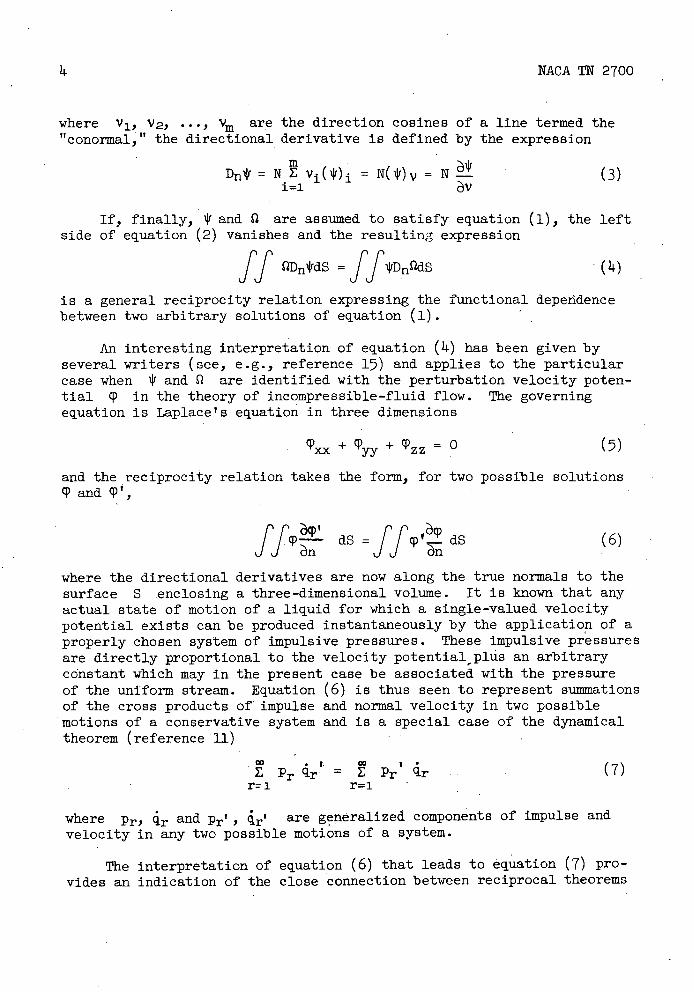
where V 1, V2, •.., V are the direction cosines of a line termed the "conormal," the directional derivative is defined by the expression
Dn 1 f = NE v1 (i) = N( 1) = N
(3) 1=1
If, finally, 4' and l are assumed to satisfy equation (1), the left. side of equation (2) vanishes and the resulting expression
ff D4'dS = ff VD nQdS
(14)
is a general reciprocity relation expressing the functional dependence between two arbitrary solutions of equation (1).
An interesting interpretation of equation (ii) has been given by several writers (see, e.g., reference 17) and applies to the particular case when 'If and fl are identified with the perturbation velocity poten-tial cp in the theory of incompressible-fluid flow. The governing equation is Laplace's equation in three dimensions
Pxx+ Pyy+ Pzz O (5)
and the reciprocity relation takes the form, for two possible solutions CP and P',
ff,l) dS =ff dS (6)
where the directional derivatives are now along the true normals to the surface S enclosing a three-dimensional volume. It is known that any actual state of motion of a liquid for which a single-valued velocity potential exists can be produced instantaneously by the application of a properly chosen system of impulsive pressures. These impulsive pressures are directly proportional to the velocity potential plus an arbitrary constant which may in the present case be associated with the pressure of the uniform stream. Equation (6) is thus seen to represent summations of the cross products of impulse and normal velocity in two possible motions of a conservative system and is a special case of the dynamical theorem (reference ii)
00 • I
E Pr r = E Pr q.r r=i r=i
where Pr, ir and Pr', i.r' are generalized components of impulse and velocity in any two possible motions of a system.
(7)
The interpretation of equation (6) that leads to equation (7) pro-vides an indication of the close connection between reciprocal theorems

NACA TN 2700 5
based upon the principles of least action and the symmetric character of Green's theorem for certain second-order differential equations. In the subsequent applications it will be convenient to proceed directly from equation ( Ii-) and seek to establish reciprocal relations between flow fields in wing theory. Such a process is well known when 1!! or f2 is replaced by the elementary solution associated with a unit source and, in this case, establishes a general solution in terms of source and doublet distributions determined by arbitrary boundary conditions. The present objective is, however, different in that one wishes to get a symmetrical dependence between two general solutions. Moreover, the apparent symmetry of equation ( )4) must be consistent with physical con-siderations so that, for example, the velocity at point A induced by a single source at point B is equal to the velocity at point B induced by a source at point A. If, in the two systems, the effective free streams or flight directions are opposed, a fore and aft symmetry occurs and the possibility of maintaining symmetry in the reciprocal relations becomes feasible.
RECIPROCAL THEOREMS IN WING THEORY
Reverse Flow for Subsonic Wings
Consider a thin wing at possibly a small angle of attack and situ-ated in the immediate vicinity of a flat surface which is designated the xy plane. For sufficiently small thickness and angle of attack the perturbation velocity potential or any of the perturbation velocity com-ponents of the wing satisfy the linearized partial differential equation of compressible flow
xx +Vyy +lfzz =O (8)
where 32= 1-MO2 = l-(U0/a0 ) 2 . Equation (8) applies in forward or reverse flow provided the corresponding free-stream Mach numbers M 0 and M0 r are equal. In the accompanying sketch a lifting wing with plan form P is indicated along with the vortex wakes as the configuration would appear if the two flow fields were superimposed. It will be assumed that the wing chord is finite and that the profiles are closed.
It is proposed to apply the gen-eral reciprocity relation to these flow fields in a manner similar to the approach used in developing the
6 NACA TN 2700
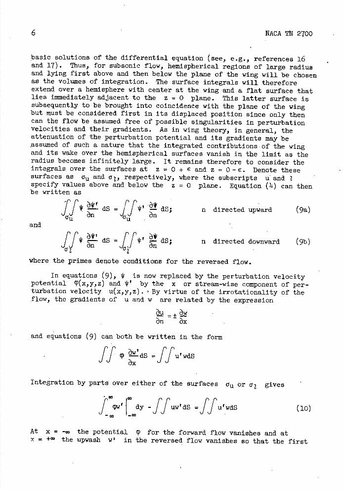
basic solutions of the differential equation (see, e.g., references 16 and 17). Thus, for subsonic flow, hemispherical regions of large radius and lying first above and then below the plane of the wing will be chosen as the volumes of integration. The surface Integrals will therefore extend over a hemisphere with center at the wing and a flat surface that lies Immediately adjacent to the z = 0 plane. This latter surface is subsequently to be brought into coincidence with the plane of the wing but must be considered first in its displaced position since only then can the flow be assumed free of possible singularities in perturbation velocities and their gradients. As in wing theory, in general, the attenuation of the perturbation potential and its gradients may be assumed of such a nature that the integrated contributions of the wing and Its wake over the hemispherical surfaces vanish in the limit as the radius becomes infinitely large. It remains therefore to consider the integrals over the surfaces at z = 0 + € and z = 0-€. Denote these surfaces as au and y , respectively, where the subscripts u and 2 specify values above and below the z = 0 plane. Equation ( Ii.) can then be written as
ff c dS= dS; n directed upward (9a) CTU 6n
u and
II'
111 — dS = dS; n directed downward (9b) _f*' 6* Cr
where the primes denote conditions for the reversed flow.
In equations (9), 4' is now replaced by the perturbation velocity
potential cP(x,y,z) and by the x or stream-wise component of per-
turbation velocity u(x,y,z). By virtue of the irrotationality of the flow, the gradients of u and w are related by the expression
—+ — —
and equations (9) can both be written in the form
ff p dS = ffut wdS
Integration by parts over either of the surfaces au or °i gives
IW f I dy _ffuw'ds =ffuwdS (10)
co —
At x = —co the potential p for the forward flow vanishes and at x = +00 the upwash w' in the reversed flow vanishes so that the first
NACA TN 2700 7
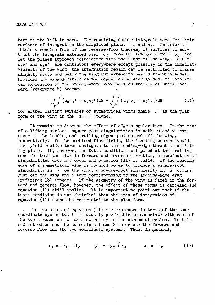
term on the left is zero. The remaining double integrals have for their surfaces of integration the displaced planes a11 and a. In order to obtain a concise form of the reverse-flow theorem, it suffices to sub-tract the integrals extended over a Z from the integrals over a11 and let the planes approach coincidence with the plane of the wing. Since w,w' and u, u' are continuous everywhere except possibly in the immediate vicinity of the wing, the integration region can be restricted to planes slightly above and below the wing but extending beyond the wing edges. Provided the singularities at the edges can be disregarded, the analyti-cal expression of the steady-state reverse-flow theorem of Ursell and Ward (reference 8) becomes
_ff( uuwu' - u 1w 2 ')dS = ff( uu' wu - u 1 'w 1 )dS (11)
for either lifting surfaces or symmetrical wings where P is the plan form of the wing in the z = 0 plane.
It remains to discuss the effect of edge singularities. In the case of a lifting surface ., square-root singularities in both u and w can occur at the leading and trailing edges. 'just on and off the wing, respectively. In the combined flow fields, the limiting process would then yield residue terms analogous to the leading-edge thrust of a lift-ing plate. If, however" ! the Kutta condition is imposed at the trailing edge for both the flow in forward and reverse direction,,a combination of singularities does not occur and equation (11) is valid. If the leading edge of a symmetrical wing is rounded so as to produce a square-root singularity in w on the wing, a square-root singularity in u occurs just off the wing and a term corresponding to the leading-edge drag (reference 18) appears. If the geometry of the wing is fixed in the for-ward and reverse flow, however, the effect of these terms is canceled and equation (11) still applies. It is important to point out that if the Kutta condition is not satisfied then the area of integration of equation (11) cannot be restricted to the plan form.
The two sides of equation (11) are expressed in terms of the same coordinate system but it is usually preferable to associate with each of the two streams an x axis extending in the stream direction. To this end introduce now the subscripts 1 and 2 to denote the forward and reverse flow and the tio coordinate systems. Thus, in general,
z 1 = z2 (12)
ru L•J
NACA TN 2700
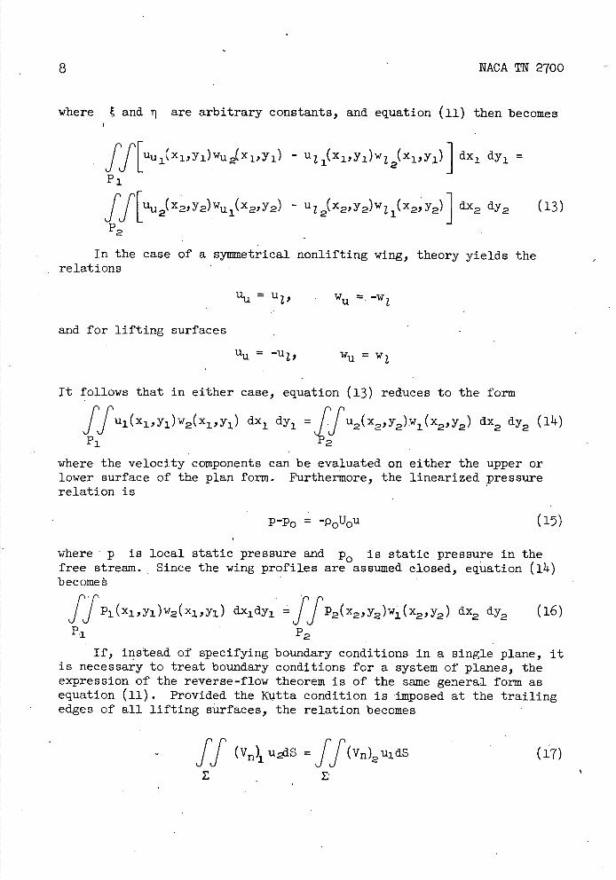
where E and ii are arbitrary constants, and equation (U) then becomes
i(xiYi)wu2(xiYi) - uz 1(x i Y1 )w 1 (xii)] dx 1 dy1 fAUU =
ff[uu (x22)wu (x2 Y2 ) - u 1 (x2 , y2)w 1 (x22)] dx2 dy2 (13)
P2
In the case of a symmetrical nonlifting wing, theory yields the relations
UU = U 1 , w =. -w1
and for lifting surfaces
u = -u1, w U = w1
It follows that in either case, equation (13) reduces to the form
fful (Xl,,Yl)W2(Xl,,Yl) dx1 dy1 =fu2(x2, y2)w1 (x2,Y2 ) dx2 dy2 (i)
where the velocity components can be evaluated on either the upper or lower surface of the plan form. Furthermore, the linearized pressure relation is
p-p0 = -pUu
(15)
where p is local static pressure and p0 is static pressure in the free stream. Since the wing profiles are assumed closed, equation (14) become
ff Pi (xi ,yi )w2 (xi ,yi ) dx1dy1 =ffP2 (x2 ,y2 )wi (x2 , y2 ) dx2 dy2 (16)
P 1 P2
If, instead of specifying boundary conditions in a single plane, it is necessary to treat boundary conditions for a system of planes, the expression of the reverse-flow theorem is of the same general form as equation (ii). Provided the Ktta condition is imposed at the trailing edges of all lifting surfaces, the relation becomes
ff (V)1 uiS =ff(vn)2uldS (17)0
NACA TN 2100 9
where the area of integration Z extends over both sides of all the wing surfaces, Vn is the component of perturbation velocity normal to and directed away from each wing, and the subscripts 1 and 2 refer to forward and reverse flow in the two axial systems.
Reverse Flow for Supersonic'Wings
The development of a reverse-flow theorem for supersonic wings parallels closely the analysis for the subsonic case. For either planar or multiplanar systems the conormal in equation ( Ii-) is, in fact, the nor-mal so long as the surface of integration is a plane parallel to the x axis. In the case of the single wing, for example, equations (9) apply where the surfaces a are slightly removed from the plane of the wing and where 1V satisfies the differential equation
(MO2-1) xx - 'yy = 0
In the limit as a approaches the z = 0 plane, the reversibility theorem takes the form of equations (ii) and (16) provided the integra-tion extends beyond the edges of the wing. It is necessary to include these edges for wings with subsonic leading and trailing edges since singularities occur in the perturbation components and the solutions are not necessarily unique. For supersonic type edges, the area of Integra-tion can be confined to the plan form of the wing and this is also true for subsonic edges provided the Kutta condition holds for all subsonic trailing edges in both the forward and reverse flow. Equation (17) relates the two possible flows in the case of multiplanar systems.
Reverse Unsteady Motion
In the case of unsteady motion at either subsonic or supersonic flight speed, the basic equation may be taken in the form
tt'xx4yy'zz° (18)
where t = a0tt, a0 is the speed of sound in the undisturbed region of the field, t' is time, and is the perturbation velocity potential or any of the perturbation velocity components. Equation (18) is the acoustic equatibn for small disturbances in three space dimensions and holds for a system of Cartesian coordinates fixed relative to the undis-turbed air. In applications to wing theory, therefore, the wings move relative tofixed axes.

10 NACA TN 2700
In the derivation of a useful theorem it is convenient to treat thin wings at small angles of attack and to assume that the motion takes place in the xy plane. The visualization of the time and geometry relations is relatively easy for two-dimensional wings moving at a uniform speed, as indicated in the sketch. The airfoil starts at time tT = 0 and
moves to the left at a constant _ 2O I velocity U0 so that the trace of
,
X the leading edge in the xt plane is x = -U0t' = -Mot and the trailing-edge trace is x = 2a - Mot.
' I ,'I\ The lines x = ±t and x = 2a ±t are 'I I the traces of the extremities of the regions affected by the acoustic waves set in motion at t' = 0 by the leading and trailing edges. In the sketch, the wing has traveled
' a time T' = T/a0 and the boundary / condition determining the wing shape
during the motion will be fixed by prescribing the value of vertical induced velocity w over the region "swept-out" of the xt plane by the wing. In order to determine a reciprocal theorem, a second wing is assumed to start at the final posi-tion of the firt wing and to move with negative velocity until it has reached the initial position of the first wing. With these concepts in mind, it follows from equation ( Ii. ) that the relation
r [2y
dxdt =11 - wdxdt (19) JJ zt
holds where and cp' are, respectively, the perturbation potentials for the forward and reverse motions. The region of integration is deter-mined by the area occupied in the xt plane by the wing, and the Kutta condition is assumed to apply to the trailing edge when in subsonic flight.
If the left side of equation (19) is integrated by parts, the general relation becomes
w'dxdt = wdxdt (20) JJ t JJ t
If the motion of a three-dimensional wing is to be studied, equations (19) and (20) must be modified to include an integration with respect to Y.
Two further. changes in equation (20) serve to simplify applications. In the first place, a symmetry is restored to the expression if two

NACA TN 2700 11
distinct systems of axes are used as in equation (lu); in the second place, the pressure relation
cp p -p0 = -p0 29 = -p 0a0 (21)
where p0 denotes undisturbed pressure, permits the introduction of pressure p in the integrands. The final expression for the three-dimensional case is, therefore,
fff p 1 (x1,y1,t 1)w2 (x1,y1,t 1 )dx1dy1dt 1 =
fff p2(x2,y2,t 2)w 1 (x2,y2,t 2)dxy2dt2 (22)
where the two motions now follow the same path in reverse directions but are referred to the two sets of oppositely oriented axes satisfying the relations
X1-X2+, Y1Y2+I1, Z1Z2, t1-t2+T (23)
where , , and T fix the relative positions of the two origins. The accompanying sketch indicates one possible orientation of the axes.U.
Equation (22) reduces to a much '2
simpler form provided further restrictions are imposed on the upwash functions w2(x,y,t1)
Z2 X,r
and w1 (x2,y2,t2). In order to fix U. L. .-the idea, consider the case in which the wings have traveled a time X
T t , (T' = T/a0 ) and a distance U0T' = M,T. Let the two systems of coordinate axes be placed such that t 1 = 0 sets the starting time of the forward motion and t2 = 0 sets the starting time of the reverse motion; the two origins are furthermore oriented such that they are at opposite ends of the root chord of the common plan form. Equation (22) fhp n hii
pT
ffdt i p 1(x 1,y 1,t 1 )w 2(x 1,y1 ,t 1)dx 1dy1 =
0 p,^
dt 2 ff 1" 1
P2(t2)
12
NACA TN 2700
where the functions w1 and w2 have an implicit dependence upon T.. If w 1 and w2 remain constant for x1 + M0t 1 = const. or
X2 + M0t 2 = const., the expression
(2) P1 T) P2T)
follows after taking a derivative with respect to T of the original equality. Equations (24) and (I ll. ) are now equivalent in form, I with T taking the role of an auxiliary parameter. In this way, certain classes of. unsteady motions can be treated simultaneously with steady motions.
In the applications to follow it will be convenient to introduce into equation ( 211) upwash functions of the indicial type; that is, functions that are zero up to a fixed time and, after experiencing a finite discontinuity, remain constant for all subsequent values of time. Such indicial or step variations can be assumed, say, for angle of attack, rate of pitch, and rate of roll since they satisfy the requirements underlying the derivation of equation (24). This choice of functions will prove to be advantageous in that the integrals of the responsive pressures will yield results relating the wing characteristics. Theorems to be given later will speak specifically of steady and indicial motions. It is to be understood, however,- that the indicial results can be further extended when the same wing is assumed to be executing identical motions in forward and reverse flight. Thus, by means of Duhamel's integral (see, e.g., reference 19), if f(t) is the response in the wing character-istic to a step variation in w at time t = 0, the response to an arbitrary variation with time of w can be written
t F(t) f(t - T)w(T)dT
6t f 0
If it is known, for example, that the lift per unit angle of attack is the same at corresponding values of time for a wing experiencing an indicial angle-of-attack change in forward and reverse flight, it fol-lows that the build-up of lift is the same at corresponding values of time for all forward and reverse motions, provided the time histories of the motions are the same. The equivalence of lift would thus be estab-lished, for instance, for oscillatory variations in angle of.attack.
APPLICATIONS
The results of the foregoing analysis may be employed to determine a number of special theorems that are particularly useful in the calcu-lation of the aerodynamic characteristics of twisted wings and of wings
(25)
NACA TN 2700
13
in nonuniform dowriwash fields. The theorems apply equally to wings act-ing either alone or, in certain cases, in combination with other wings or with cylindrical bodies having their generators alined with the x axis. Moreover, they apply not only to wings in steady motion but also to wings performing unsteady motions of the indicial type, or unsteady motions derivable therefrom. For wings in more complex unsteady motions, however, it will be necessary to refer to the more general results of equation (22). Some problems of this nature will be described at the end of this section.
The applications to be included are exact within the framework of linear theory and involve no further restrictions on the wing plan form or Mach number except in certain indicated cases where it will be con-venient to use results based on slender wing theory. The examples are intended to be representative in nature.
REVERSAL THEOREMS - STEADY AND INDICIAL MOTIONS
Reversal theorems are defined here as relations between the aero-dynamic characteristics of identical wings executing the same type of motions in forward and reverse flight. The results presented in this section apply not only to single wings in steady motion but also to com-binations of wings, as in cascades or multiplanes, performing either steady motion or motions of the indicial type.
Drag of Symmetrical Nonlifting Wings
The drag of a symmetrical, sharp-edged wing in linear theory may be determined by integrating over the plan form, the product of the pressure and the slope in the x direction of the wing surface; when the wing has blunt edges with slopes having square-root singularities, these singular-ities yield an added contribution (reference 18). In general, therefore, the drag D of a symmetrical section is given by
DDe+ 2 ffP )dS (26)
where De is the drag attributable to the edges.
If the subscripts 1 and 2 reverse flow, respectively, an in equation (23), local slopes
dz1 (x1,y1,T)
dx1
refer to the same wing in forward and I with the two systems of axes introduced are related , as follows
lu - - - dx: 2 lu
dz2 (x2, y2 , T)(27)

l
NACA TN 2700
Equations (26) and (27), together with the reciprocal relation (24), yield
"dz \ = -
= (D2 -2 1 dS1 = -2 ff dS1e)i dx 21)u
.P1 p1
(dZ
(dXjzi
-2 ff2 dS = 2 JfP2 2 D2 - ( De) (28)
P2 P2
Since the geometry of the wing is fixed, the edge contributions are the same,
(De) 1 = (De)
(29)
and, consequently,
D1 = D2 (30)
which confirms the relation stated in reference (9).
THEOREM: The pressure drag in steady or indicial motion of sym-metrical nonlifting wings is the same in forward and reverse flight.
Lift on Flat-Plate Wings
The lift L of a wing may be determined by integrating the differ-ential pressure L,p = Pz - Pu over the wing plan form, thus
L=ffLPdS ' (31)
For flat-plate wings, the local angle of attack of the wing surface - is a constant
ct1(x1,y1,T) = = conat., a2(x2,y2,T) = 2 = const. (32)
Application of equations ( 31), ( 32 ), and (24) yields the following:
L1 a 2 =4fLPi cL2dSi = ftp2cti ds2 1 = L2a
or
L1 /CL = L2/M2 (33)
NACA TN 2700 15
THEOREM: The lift per unit angle of attack of flat-plate wings in steady or indicial motion is the same in forward and reverse flight.
This theorem generalizes the relation previously given by Brown (refer-ence 5) for steady motion.
Damping in Roll of Flat-Plate Wings
The rolling moment L' exerted on a wing, following the usual sign convention, is given by
L' = Ifi^s (31k)
The local angle of attack due to rotation about the x axis is
2 = p2 ty = - p21y1
U0 U0 U0 (35)
where p' is the angular velocity of roll, assumed constant. Applica-tion of equations (34 ), (35), and (24) yields the following:
p2 T L1 T = -y1p1dS1 = fy2ApjdSj =
U0 uJ P1
U0 L,
Pt L? 1' ff - t': 1f y2ip2dS2 -
1 2 -ii;
y1 p2dS2 = Uc J . U0
P2 P2 or
L11/p1' = L2T/p2t (36)
THEOREM: The rolling moment per unit angular rolling velocity of flat-plate wings in steady or indicial motion is the same in forward and reverse flight.
Damping in Pitch of Flat-Plate Wings
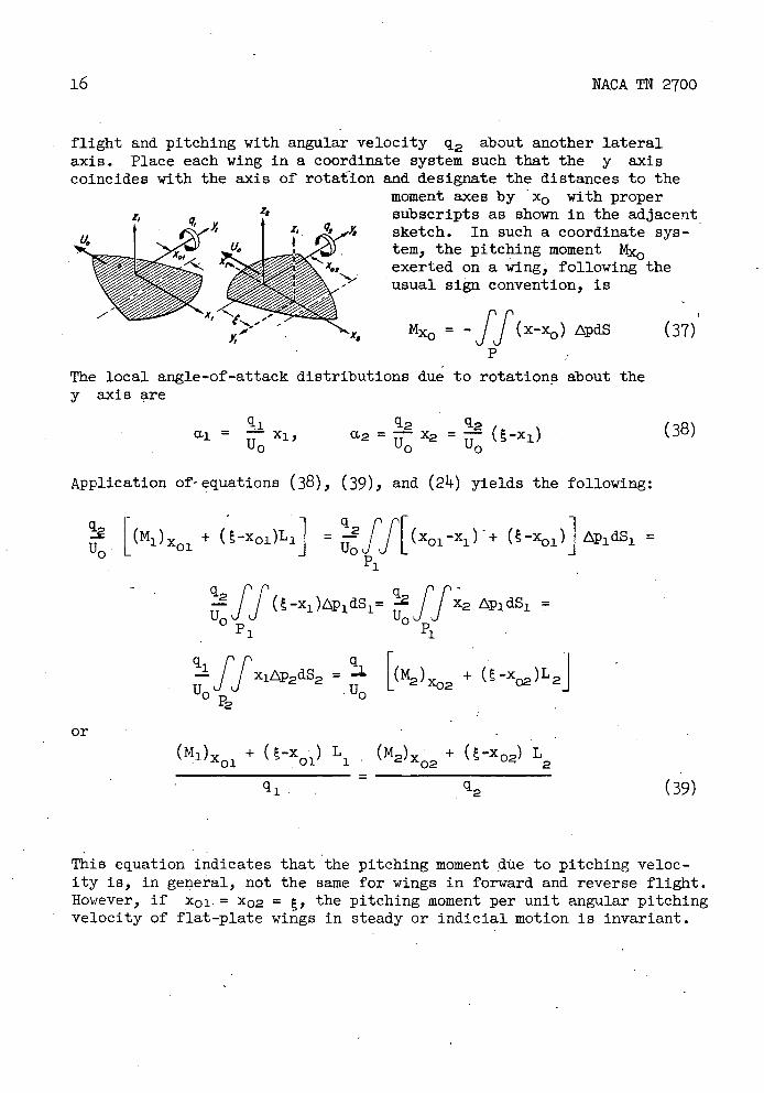
Consider a wing, first, in forward flight and pitching with a uni-form angular velocity q1 about a lateral axis; second, in reverse
'I As Mx0 = ff(x-xo ) ApdS .(37)
16 NACA TN 2700
flight and pitching with angular velocity q2 about another lateral axis. Place each wing in a coordinate system such that the y axis coincides with the axis of rotaiion and designate the distances to the
moment axes by x0 with proper 4 subscripts as shown in the adjacent
f z, q, Ys sketch. In such a coordinate sys-tem, the pitching moment
,
exerted on a wing, following the usual sign convention, is
The local angle-of-attack distributions due to rotations about the y axis are
qi q2 q2 a —xj,
U0 0 0
Application of-equations (38), (39), and (2 1 ) yields the following:
Ci2. [(Ml )x + (-xoi)Li] u
P1
= Cr[ (x01 _x1) - + ( _xoi )]APidSi = JJ L -
rr(_X1)P1dS1 ff -
X2 p1 dS1 = u0JJ P 1 P1
if X1AP2dS2 ='0 P2
[2 + (-x)L2j -
or+ (-x )
01 1 L (M2) + ( -x 02) L • 2
q 1 -
This equation indicates that the pitching moment due to pitching veloc-ity is, in general, not the same for wings in forward and reverse flight. However, if X01-= x02 = , the pitching moment per unit angular pitching velocity of flat-plate wings in steady or indicial motion is invariant.
(38)
(39)

NACA TN 2700 17
SPECIAL RECIPROCAL THEOREMS AND APPLICATIONS
In the following section, several special reciprocal theorems will be derived and applications will be illustrated. Reciprocal theorems, in contrast to reversal theorems treated in the preceding section, are defined here as relations between the aerodynamic properties of wings in forward and reverse flight that have dissimilar camber, twist, and thick-ness distributions but have the same plan forms. The motions ma or may not be similar, although it is assumed in this section that both wings are in either steady motion or unsteady motion of the indicial type. As noted in the preceding section, the results apply equally to wings act-ing alone or in combination.
Symmetric Norilifting Wings - Steady Motion
The problems of paramount interest in the application of the general relations are found from considerations of pressure integrals over lift-ing surfaces; such problems will be given detailed treatment later. In the present section, a brief indication is given of the manner in which useful results can be derived for symmetric wings. The discussion will be limited to steady-state, two-dimensional, subsonic pressure fields although fairly obvious extensions can be carried out.
If the geometry of a real symmetric airfoil is prescribed, the theoretical pressure distribution exists and is unique. If, however, the pressure distribution is prescribed, a real airfoil does not neces-sarily exist, but by means of reciprocal relations it is possible to derive certain conditions of compatibility that need to be imposed. Con-sider, therefore, the two subsonic solutions
u1 (x1 ) = 0, w1(x1) = Uo/fa2_x12; -a(x1<a
and
u2(x2), w2(x2)
The first solution has square-root singularities in w at each end of the airfoil and, correspondingly, singularities in u occur just ahead of the point x -a and just behind x a. On the other hand, equa-tion (14) certainly applies if w2 is zero at x = ±a. Ifthe origins
18
NACA TN 2700
of the two systems of axes are at the same position, it follows from equation (iii-) that u2(x) must satisfy the relation
0 =fa u2(x2)dx2 (4o)-a 1a2_x22
This result is useful in the calculation of airfoil shapes involving a change in pressure distribution from that of a known reference profile. The restriction on w2 at the nose and tail implies that the derived and reference profiles have the same slope and radius of curvature at those points. The restriction on U2, as given in equation (140), can be interpreted as a condition that must exist by virtue of the fact that the drag of an airfoil in two-dimensional potential flow is zero.
As a second example, consider the solutions
tUo -tx1U0 u1 (x1 , = -, w1(x1)
2a = 2a/c2_xi2_a<x1<a
that represent velocity and slope of a thin ellipse of thickness t and chord 2a. If w2 is chosen as above, such that it vanishes at the nose and tail of the airfoil, 'if u 2 is the corresponding velocity distribu-tion, and if the two sets of axes are as before, equation (iIi-) yields
dZ2 dx = - fu2(x2)x2dx2 L dxj i-La Aja2_ x22
From this result, together with the general closure condition
- adx = f1(x)d = 0 (Ia)
-a dx Uo_a
a necessary condition for the closure of the second airfoil is
a uth(x2)x2dx2
J _____ =0 (42)-a a-x2
NACA TN 2700 19
As a final example, consider the solutions for -a<x1<a
u 1(x 1) = 2tU0 (a-2x1),
3
wi(xi) - 2t U0 2x1 2 -. ax1-a2
3 A/ra2 /2 - x2
representing velocity and slope of a thin Joukowsky type airfoil. In this case, WI vanishes at the tail and the downwash distribution w2 for the reverse wing may have a square-root singularity at the nose. The nose of the first wing is, however, blunt and for equation (3)4) to apply the second wing must have a cusped tail. Under these conditions, equation (11 ) yields
2t UO2
•I'a (a-2x) d = 2t U0 a 2x 2- ax1 - a2
u2(x2) dx2 3a/a2 dx2 3a2J_a. 1a2 - x12
Making the substitution x1 =-x2 in this equation and integrating the left side by parts, one has
a
[
-,a a
} f 2x22 + - a2
xi_)z2j _2f z2(x1)dx-a [a2_x22
u2(x2)dx2
-a -a
For all real airfoils with cusped trailing edges, therefore, the area A2 can be expressed as
a22 2 - a2 u2(x2) A2 =
dx2 (4-3) La f a2 - x2 - U0
Lift - Steady and Indicial Motion
• The reciprocal theorems offer considerable advantage in the calcu-lation of the lift of wings having a nonuniform angle-of-attack distri-bution or of wings in a stream having nonuniform flow directions. For these applications, it is convenient to consider a special form of the reciprocal theorem which relates the lift on a wing having arbitrary distribution of local angle of attack to that of the flat-plate wing of identical plan form in flight in the reverse direction. Since the
20
NACA TN 2700
solution of this latter problem is often known or can be found rela-tively easily, the solution of the original problem is facilitated in many instances.
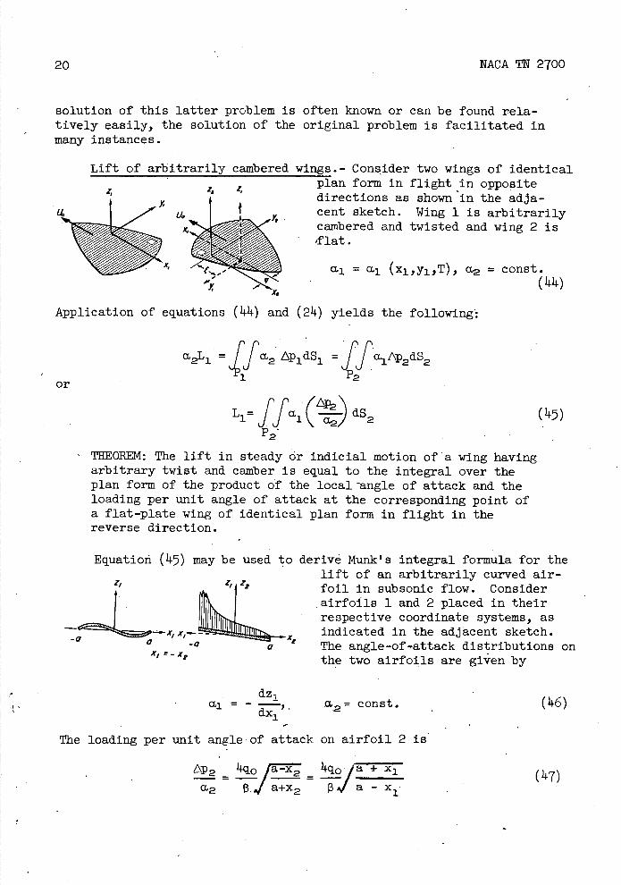
Lift of arbitrarily cambered wings.- Consider two wings of identical plan form in flight in opposite
za z,directions as shown in the adja-cent sketch. Wing 1 is arbitrarily X"::^ 1.LLXcambered and twisted and wing 2 is flat.
a.1 = a.1 (x1 ,y1 ,T), ct2 = const. (I4.)
Application of equations (41) and (21 ) yields the following':
=fa2 Ap1dS1 =ffaiP2ds2
or
L1= Ifa.( dS (5)
THEOREM: The lift in steady or indicial motion of a wing having arbitrary twist and camber is equal to the integral over the plan form of theproduct of the local angle of attack and the loading per unit angle of attack at the corresponding point of a flat-plate wing of identical plan form in flight in the reverse direction.
Equation (45) may be used to derive Munk's integral formula for the lift of an arbitrarily curved air-foil in subsonic flow. Consider airfoils 1 and 2 placed in their
LEE -_ X IIj_-_
respective coordinate systems, as indicated in the adjacent sketch. T x, The angle-of-attack distributions on the two airfoils are given by
dz1 al = -
2 const. xl
The loading per unit angle-of attack on airfoil 2 is
A^a+ 2 1, H
U2 V7.
(16)
()+7)

NACA TN 2700 21
where q is free-stream dynamic pressure (-1 pU 2 ). Substitution into equation (11.7) yields the lift formula 2
+xi a z
i
a
L, Or . dx1 (11.8) -a dxifa - x1-
The corresponding formula for the lift of a tier of curved airfoils may also be derived similarly from the expression for the loading on an equivalent tier of flat airfoils.
- The load distribution per unit angle of attack for a two-dimensional supersonic wing is
A2
M2 P
and., from equation (117), the lift is
pa dz1
L 1 = - - dx1 (50) -
The extension of this result to include supersonic-edged wings with straight trailing edges leads to a result given originally-by Lagerstrom and Van Dyke (reference 20). If, as in the sketch, the sweep angle of the straight edge is A. the load distri-bution per unit angle of attack of the reversed wing is
11.q0 cos A (5i) 'IXf M2 = /i_Mo2 Cos 2 A -
and the lift is
-'l.a crdz
L1 = -u dx1dy1 (52) /sec2A-MO2JJ dX1
P1
A less obvious application yields the build-up of lift with time of an arbitrarily cambered two-dimensional supersonic airfoil starting
(11.9)
22
NACA TN 2700
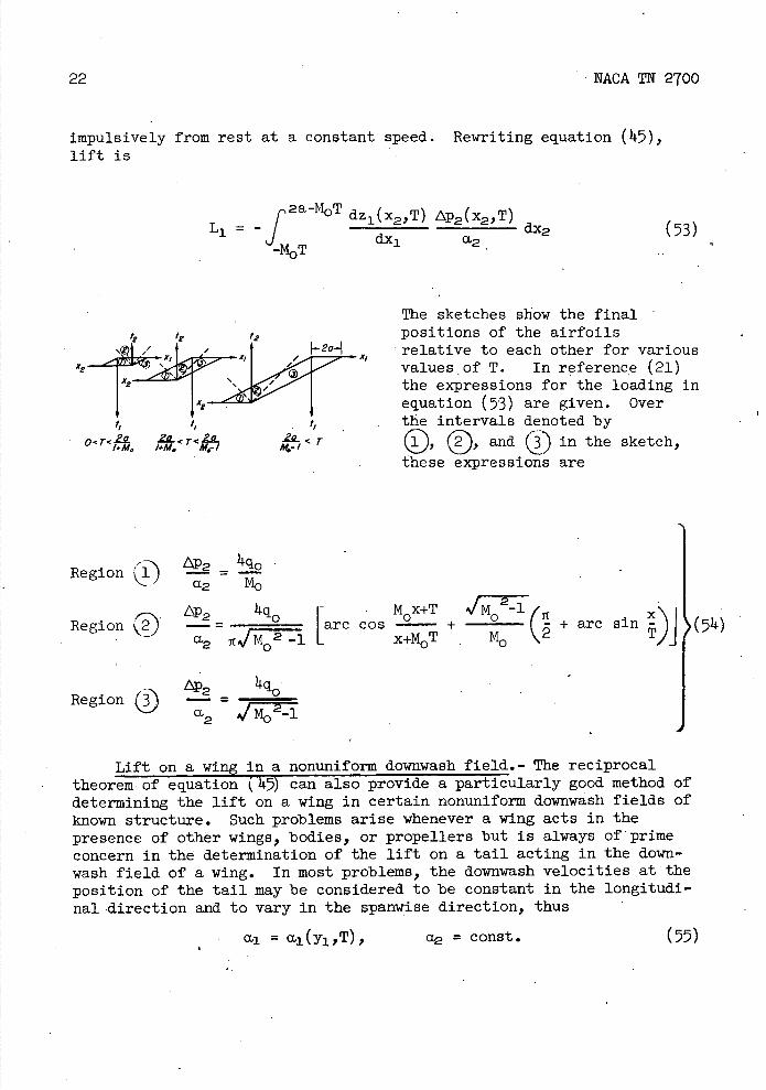
impulsively from rest at a constant speed. Rewriting equation (1.i-5), lift is
2a-M0T dz 1 (x2,T) p2(x2,T) L1 =- r dx2
d.x1 a2 (53)
4 '2
X2X2
xl
I,
O <T<5-7 < 7
/.M I#M
The sketches show the final positions of the airfoils relative to each other for various values of T. In reference (21) the expressions for the loading in equation (53) are given. Over the intervals denoted by
0 and in the sketch, these expressions are
RegionLP 10 .l) - = - - a2 M0
,- Lp2 1q0 [ MX+T /2l Region 2J -= - arc cos + ( - + arc sin - 1! (!)
a2 -1 L x-i-M0T M \2 TJJ
Region® a2 /2l
Lift on a wing in a nonuniform downwash field.- The reciprocal theorem of equation ('45) can also provide a particularly good method of determining the lift on a wing in certain nonuniform downwash fields of known structure. Such problems arise whenever a wing acts in the presence of other wings, bodies, or propellers but is always of prime concern in the determination of the lift on a tail acting in the down-wash field of a wing. In most problems, the downwash velocities at the position of the tail may be considered to be constant in the longitudi-nal-direction and to vary in the spanwise direction, thus
a1 = a1 (y1 ,T), a2 = const. (55)
NACA TN 2100
23
and -
Li - = ffai CIS, =
() dy2 (56)
\ a2) P2
where 12 is the span load distribution associated with the load distri-bution AP2. Summarizing, the lift in steady or indicial motion of a wing in a downwash field which varies across the span is equal to the integral over the span of the product of the local angle of attack and the span loading per unit angle of attack at the corresponding spanwise station of a flat-plate wing of identical plan form in flight in the reverse direction. This statement generalizes the result given recently by Alden and Schindel (reference 22) for steady flow about wings having supersonic leading and trailing edges and streamwise side edges.
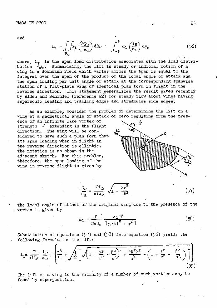
As an example ) consider the problem of determining the lift on a wing at a geometrical angle of attack of zero resulting from the pres-ence of an infinite line vortex of strength I' extending in the flight direction. The wing will be con-sidered to have such a plan form that its span loading when in flight in the reverse direction is elliptic. The notation is as shown in the adjacent sketch. For this problem, therefore, the span loading of the wing in reverse flight is given by
2L:/2
. (57) -12
0'2TI SCL2
The local angle of attack of the original wing due to the presence of the vortex is given by.
y1-3 (8) a,121tU0 1(y1-3)2 +
Substitution of equations following formula for the
(57) and (58) into equation (56) yields the lift:
L 4p272 Y2 p2
)JJ (59)
The lift on a wing in the vicinity of a number of such , vortices may be found by superposition.
24 NACA TN 2700
Lift due to deflection of .a portion of the wing surface.- Let a portion P' of the surface of 1ing 1 be deflected a constant angle 6 and the remainder of the wing be a flat plate alined with the free-stream direction. Let wing 2 bea flat-plate wing inclined at an angle of attack a, thus
6onP' =
a2 = const. (60)
0 elsewhere
Substitution of equation (60) into (47) yields the following result:
L1 rr,'p2\2 1)
The lift in steady or indicial motion per unit angular deflection of a portion of the wing surface is thus equal to the lift per unit angle of attack on the corresponding portion of a flat-plate wing in flight in the reverse direction. This generalizes a result given previously by Morikawa and Puckett (reference 23) for steady flow about low-aspect-ratio wings.
This rule is very useful in the determination of the lift resulting from the deflection of a flap or-control surface. This is particularly true for supersonic speeds since the loading on the related flat wing is often a constant over a large portion of the area of integration.
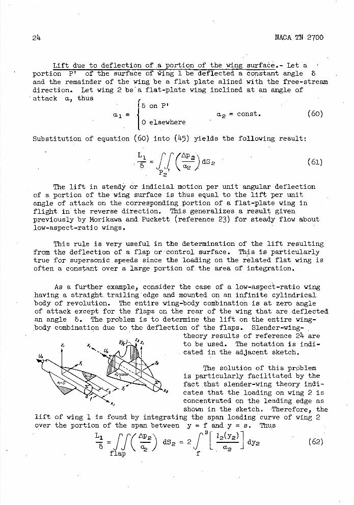
As a further example, consider the case of a low-aspect-ratio wing having a straight. trailing edge and mounted on an infinite cylindrical body of revolution. The entire wing-body combination is at zero angle of attack except for the flaps on the rear of the wing that are deflected an angle 8. The problem is to determine the lift on the entire wing-body combination due to the deflection of the flaps. Slender-wing-
theory results of reference 24 are l(Yz) i l to be used. The notation is mdi-
11 __/ I III . . cated in the adjacent sketch.
The solution of this problem aelc is particularly facilitated by the
fact that slender-wing theory mdi-' cates that the loading on wing 2 is
K, concentrated on the leading edge as shown in the sketch. Therefore, the
lift of wing 1 is found by integrating the span loading curve of wing 2 over the portion of the span between y = f and y = s. Thus
/ p2\
=ffç L -) dS2 =
12 (Y2)dy2 (62)
a2 flap f
NACA TN 2700 25
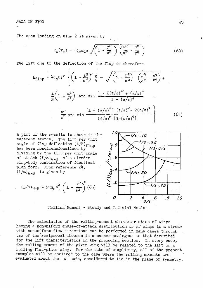
The span loading on wing 2 is given by
y2\\ (a
22 a2'
12 (y2 ) = f(17 - (63)
The lift due to the deflection of the flap is therefore
Lflap =
4q 6S{ (
- - a Lf2 P 4)
1 s2 2i - +
+ a' 1 - 2(f1c) 2 + (a/s)
- 1— 2 4) arc sin 1 - (a/s) 4
+
a2 [1 + (a/s)4 I (f/s)2 - 2(a/s)
are sin
(64) (f/s)2 [i-(a/s)]
A plot of the results is shown in the 1.0
adjacent sketch. The lift per unit angle of flap deflection (L/6)fla.n has been nondimensionalized by dividing by the1ift per unit angle of attack (L/a)_B of a slender .6 wing-body combination of identical plan form.. From reference 24, ( L/a)W_B is given by
4
2 a22 = 2q0 s 1 - (65) ) 92
NN Wa 5 Rom. - E0 0-APAP rA
0
0 .2 .4 .6 .8 10 c/s
Rolling Moment - Steady and Indicial Motion
The calculation of the rolling-moment characteristics of wings having a nonuniform angle-of-attack distribution or of wings in a stream with nonuniform-flow directions can be performed in many cases through use of the reciprocal theorem in a manner analogous to that described for the lift characteristics in the preceding section. In every case, the rolling moment of the given wing will be related to the lift on a rolling flat-plate wing. For the sake of simplicity, all of the present e*amples will be confined to the case where the rolling moments are evaluated about the x axis, considered to lie in the plane of symmetry.
26
NACA TN 2700
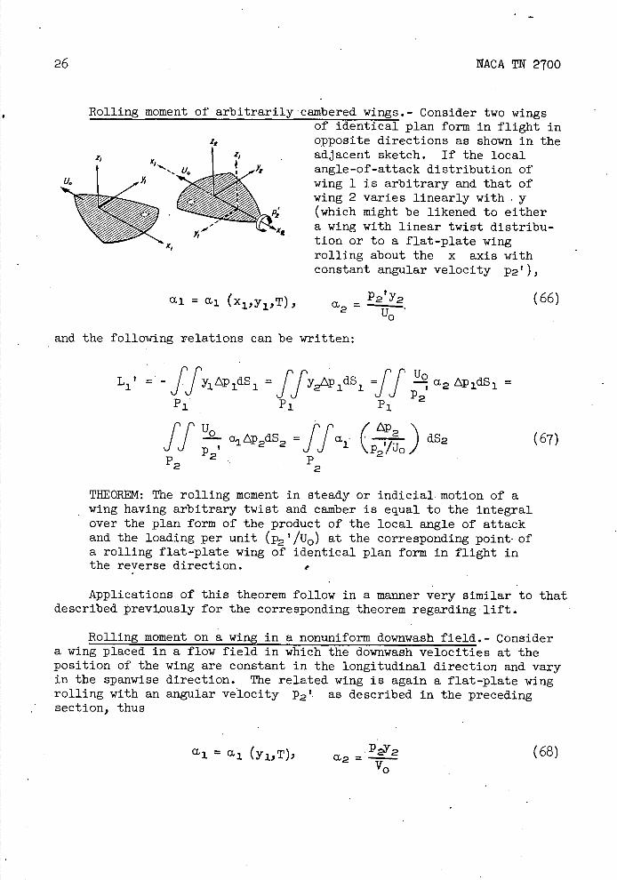
Rolling moment of arbitrarily cainbered wings.- Consider two wings of identical plan form in flight in opposite directions as shown in the adjacent sketch. If the local angle-of-attack distribution of wing 1 is arbitrary and that of wing 2 varies linearly with y (which might be likened to either a wing with linear twist distribu-tion or to a flat-plate wing rolling about the x axis with constant angular velocity p2'),
= i (x1,y1,), p2y2 (66) Uo
and the following relations can be written:
L1 ' = - = ff y2Ap 1dS 1r
2 tp 1dS 1 =
H-Off ap2dS2 =ff . (P2'o) dS2 (67) P t
P 2 p 2 2
THEOREM: The rolling moment in steady or indicial motion of a wing having arbitrary twist and camber is equal to the integral over the plan form of the product of the local angle of attack and the loading per unit (p2 '/u0) at the corresponding point-of a rolling flat-plate wing of identical plan form in flight in the reverse direction.
Applications of this theorem follow in a manner very similar to that described Previously for the corresponding theorem regarding lift.
Rolling moment on a wing in a nonuniform downwash field. - Consider a wing placed in a flow field in which the downwash velocities at the position of the wing are constant in the longitudinal direction and vary in the spanwise direction. The related wing is again a flat-plate wing rolling with an angular velocity P2 '- as described in the preceding section, thus
a]. = a1 (y1,T), a2 .p2y2 (68) =V0
NACA TN 2700 27
The rolling moment of the first wing is then given by
P 8 l 2=](Li(
L1 ' =ffa2 (T2L^uo)2 -s
2I/)dY2 (69)
P2
or, in words, the rolling moment in steady or indicial motion of a wing in a downwash field which varies across the span is equal to the integral over the span of the product of the local angle of attack and the span loading per unit (p2 '/uo) at the corresponding spanwise station of a rolling flat-plate wing of identical plan form in flight in the reverse direction.
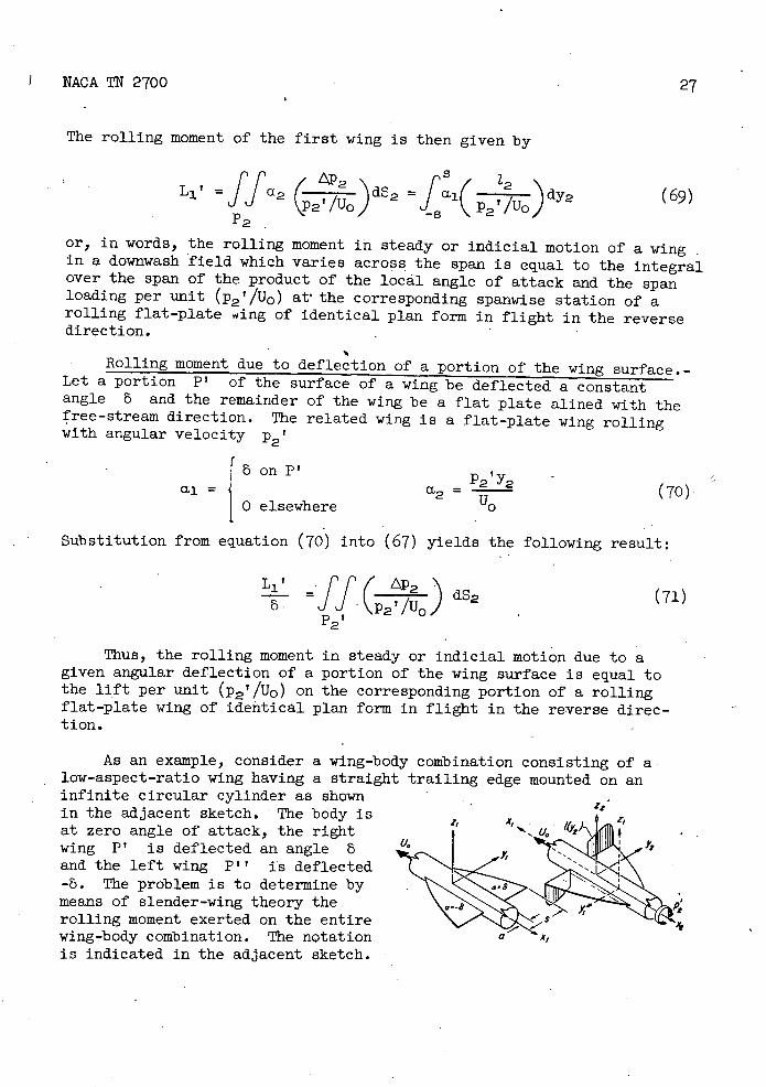
Rolling moment due to deflection of a portion of the wing surface.- Let a portion P' of the surface of a wing be deflected a constant angle 6 and the remainder of the wing be a flat plate alined with the free-stream direction. The related wing is a flat-plate wing rolling with angular velocity p2'
ronP'=p2ty2
0 elsewhere2 U0
Substitution from equation (70) into (67) yields the following result:
ff 2o . P2'/U0)
P2
Thus, the rolling moment in steady or indicial motion due to a given angular deflection of a portion of the wing surface is equal to the lift per unit (p2 '/uo) on the corresponding portion of a rolling flat-plate wing of identical plan form in flight in the reverse direc-tion.
As an example, consider a wing-body combination consisting of a low-aspect-ratio wing having a straight trailing edge mounted on an infinite circular cylinder as shown in the adjacent sketch. The body is
ZI X1
at zero angle of attack, the right wing P' is deflected an angle 6 and the left wing P'' is deflected -. The problem is to determine by means of slender-wing theory the rolling moment exerted on the entire wing-body combination. The notation is indicated in the adjacent sketch.
(Li = (70)
dS2 (7')

28
NACA TN 2700
- 8 on left wing, F'' 11= Oonbody
+ 8 on right wing, P'Pc:Y2
=. (72)
Since slender-wing theory indicates that the loading on wing 2 is con-centrated on the leading edge, the rolling moment of wing 1 can be found by integrating the span loading on wing 2.
L 1' = ffai / 2 p2h/Uo)
dS 2 = -8_____ _
2 __ dy = dy2fa _uoJ (p,/
P2t p 2 , NO
28fap2/Uo)
where, from reference 25,
12 a4 2as q0s2
•\ arc cos
2 = 1+
* s+a2)+
2 +72 y2 - - +
2 a2cosh
2 2 + a2) (S2 - a2)1
- are
(y2 - a2)(s2 + a2
The resulting expression for the rolling moment is
(1- - + R 1 + - are cos - - ' =q8sF(P,k) [R2 / 2 4)( 2 2R
2 +) 3n 0
3
E(,k)- 2 H4 2 2 2H
2 R(l-R)
+
(l+arc COB
+ +
! n 2R +
R2) (1 + arc cos - - 37c :1+R2 3 it l+H
where (74)
R=a/s
tP= arc sin
_-_R4 All + H2
=
o .2 .4 .6 .8 10 a/$
NACA TN 2700
NE
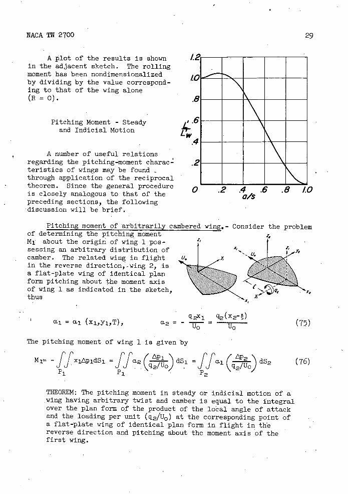
A plot of the results is shown in the adjacent sketch. The rolling moment has been nondiinensionalized by dividing by the value correspond-ing to that of the wing alone (R = 0).
Pitching Moment - Steady and Indicial Motion Lp
A number of useful relations regarding the pitching-moment charac-teristics of wings may be found through application of the reciprocal theorem. Since the general procedure is closely analogous to that of the preceding sections, the following discussion will be brief.
Pitching moment of arbitrarily.cambered wing.- Consider the problem of determining the pitching moment 4 M1 about the origin of wing 1 pos- sessing an arbitrary distribution of
U. camber. The related wing in flight in the reverse direction,-wing 2, is a flat-plate wing of identical plan form pitching about the moment axis of wing 1 as indicated in the sketch, qt
thus
q2x1- q2 (x2-) cL1 = a 1 (x 1, y 1,T), a2 = - ( 75) T u0
The pitching moment of wing 1 is given by
- xipidSi = ffa2 (qo) dS1 = ff (T0) dS2 (76) ff
Pi P1 P2
THEOREM: The pitching moment in steady or indicial motion of a wing having arbitrary twist and camber is equal to the integral over the plan form of the product of the local angle of attack and the loading per unit (q2/u0 ) at the corresponding point of a flat-plate wing of identical plan form in flight in the reverse direction and pitching about the moment axis of the first wine.

30
NACA TN 2700
The necessity for pitching wing 2 about the moment axis of wing 1 may be removed by considering wing 2 to be re-expressed in terms of two component wings having angle-of-attack ' distributions given 'by
q2 , (x21 - x02 ,) q2, (X021-)
M2 = ' a2'' =
= const. (77) U0 U0
Wing 2' is thus pitching with angular velocity q2t about an axis at x2 1 = x02 t and wing 2 1 ' is a flat-plate wing at a constant angle of attack. The pitching moment on wing 1 is then given by
= ff (LP2I ai
\'
2 i0)2'
+ ff1 dS2'
P2,1
ff(Ij (LPT,'I a 1 ( dSt+(x202 -) ( dS , ( 78) 2' !u
J'\. a2 i 2
P2 t P2,1
Applications of pitching-moment theorem.- Since the application of equation (76) or (78) to problems analogous to those discussed in the preceding sections proceeds in a straightforward mariner, the following discussion will be abbreviated.
If wing 1 i a flat-plate wing, a 1 is constant and equation (78) simplifies to
M1 L2 - = - +(x02' - ) a 1 q2 /u0 a2,,
where L2 v is the lift on wing 2' pitching about x 2 = x02 1, and L211 is the lift on an inclined flat-plate wing. Equation (79) may be expressed in terms of conventional stability derivatives as follows:
X02 I_
(c)(
= (cLq ) 2 t +) ( CLa)2 (80)
(79)
NACA TN 2700
31
2.5
2.6
'.5
/.6
.5
.5 £0' 15 20 25 Chord lengths traveled
If a 3 is independent of x and varies only in the spanwise direction, that is, if a = ct 1(y 1), the pitch-ing moment on wing 1 is given by the following equation, analogous to equation (56) for lift,
- S
M1 f dy2v + (xo2? _) f a1(1 ) dy2 1 ' ( 8,1)
If a portion P' of the surface of wing-1 is deflected a constant angle 5. and the remainder of the wing is a flat plate aimed with the free-stream direction, the following relations hold:
SonP'
0 elsewhere
and
r' 8 Li J qi/u0) dS2,
+ (xo2_)ff(2' dS2,v (82). M2,
P 1 2 , F'2,,
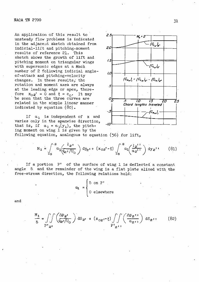
An application of this result to unsteady flow problems is indicated in the adjacent sketch obtained from indiclal-lift and pitching-moment results of reference 21. This sketch shows the growth of lift and pitching moment on triangular wings with supersonic edges at a Mach number of 2 following indicial angle-of-attack and pitching-velocity changes. In these results, the rotation and moment axes are always at the leading edge or apex, there-fore x02' = 0 and E = co . It may be seen that the three curves are related in the simple linear manner indicated by equation (80).
At
-.-- /I_ ("Lq/p'
I
(Cm ) = (Ca q ), - (CL.),.
0 >x1 >-Mot1,. for
2a-M0t 1 >x1 >-M0tj., a1 (x1 ,t1 ) = ag = const.
0 t1 2a/M0
2a/M0 ^ t1
32
NACA TN 2700
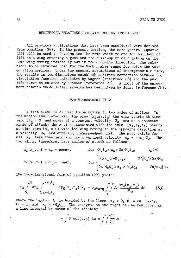
RECIPROCAL RELATIONS INVOLVING MOTION INTO A GUST
All previous applications that have been considered were derived from equation (24). In the present section, the more general equation (22) will be used to develop two theorems which relate the build-up of lift on a wing entering a gust and the build-up of circulation on the same wing moving Indiclally but in the opposite direction. The rela-tions to be obtained hold for the Mach number range for which the wave equation applies. Under the special assumptions of incompressible flow, the results in two dimensions establish a direct connection between the circulation function calculated by Wagner (reference 26) and the gust lift-curve calculated by Kussner (reference 27). A proof of the agree-ment between these latter results has been given by Sears (reference 28).
Two-Dimensional Flow
A flat plate is assumed to be moving in two modes of motion: In the motion associated with the axes (x 21 z 21 t2 ) the wing starts at time' zero (t2 = 0) and moves at a constant velocity U0 and at a constant angle of attack; the motion associated with the axes (x1 ,z 1 ,t 1 ) starts at time zero (t 1 = 0) with the wing moving in the opposite direction at a velocity U0 and entering a sharp-edged gust. The gust exists for all xl less than zero and has a vertical velocity wg = mg U0 . The two wings, therefore, have angles of attack as follows:
(12(x2)t2) = = const. for -M0t2< x2 < 2a-M0t22 t2 >0
The two-dimensional form of equation (22) yields
a2fTdtlf_M0t1 pg(x1 ,t 1 )c1 = poaoagff 2(:t2) dS (83)
0 2a-M0t1 A
where the region A is bounded by the lines x = 0, x1 = 2a - M0t1, t 1 = T, and x1 = -M0 t 1 . The integral on the right can be rewritten as a line integral by means of the identity
_fp cos(t,n) ds =ff d S
'3,,
2,-
2
I C, I I— d'
'-I Cig
-
Cl
I
C,a
NACA TN 2700 33
and equation (83) becomes
- afT Lg(ti)dti = poaoagf ACP2CoS (t2,n)ds
where the line integral extends around the boundary of the region A. Since ACP2 vanishes on the lines x2 = -M0t2 and t2 = 0, the equation becomes -
• T 2a 2a-x a2f Lg(ti)dt i = poaoag12a_MoT 2 (2, M 2)2
• o 0
Differentiation with respect to T yields
a2 Lg (T) p0U0aP2 (2a-M0T,T)
The discontinuity in P2 is evaluated at the trailing edge at time T and is therefore equal to the circulation r2 of the airfoil at time T. The equality thus becomes
Lg(T) - r2(T)
p01J0 (814.) ag a2
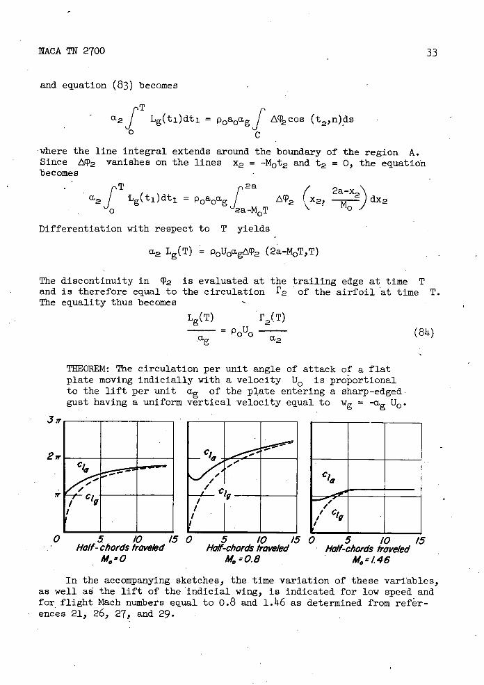
THEOREM: The circulation per unit angle of attack of a flat plate moving indicially with a velocity U0 is proportional to the lift per unit ag of the plate entering a sharp-edged gust having a uniform vertical velocity equal to Wg = °g U0•
0 5 /0 15 0 5 /0 15 0 5 /0 15 Half- chords traveled Hoff-chords traveled • Hoff-chords traveled
M0 0 M0=0.8 - M.-Z46
In the accompanying sketches, the time variation of these variables, as well ad the lift of the indicial wing, is indicated for low speed and for flight Mach numbers equal to 0.8 and 1.146 as determined from refr-ences 21, 26, 27, and 29.

3
NACA TN 2700
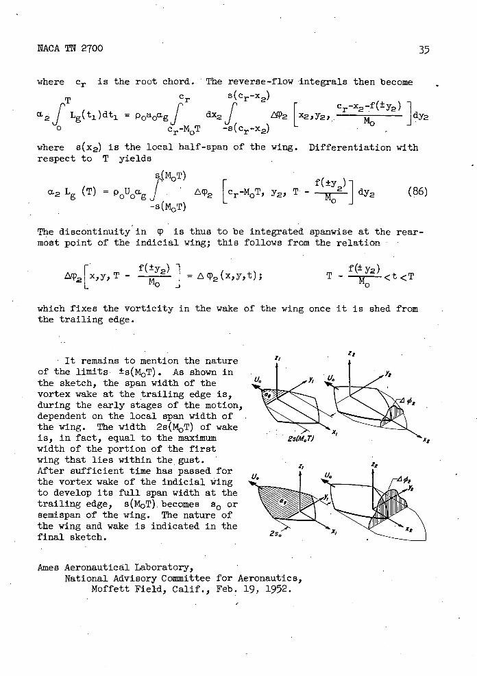
Three-Dimensional Flow
The extension of the above results to three dimensions is straightforward. The origin of the x 1 , y, z 1 , t1 axes is assumed to be initially at the foremost point of the wing in reverse motion. The two wings have, respectively, angles of attack a,2 = const. over the reverse moving plan form for all values of time and °g = const. over the region occupied simultaneously by the forward moving wing and the gust. Equation (22) gives
2 dt1 ff APg (x1, y1 ,t1 ) dxj dy1 Jo
p(t1)
poaoag fff2( X2 Y21 2)
dx2dy2dt2 (85)
The integral on the right can be rewritten as a two-dimensional surface integral by means of the identity
- ffP cos (t,n)dS = 11APt- dxdydt and equation (85) becomes
Q2 f Lg (t 1 ) dt 1 = poaoagff 2 cos (t2 ,n) dS2
where the integral on the right extends over the boundary of the volume in x, y21 t2 space occupied by the wing and the gust. The value of LP2 must, of course, vanish on the leading edge of the wing and at t2 = 0. In order to fix the limits of integration, suppose 'the wing is symmetrical about its longitudinal axis and let the leading edge of the forward wing be given by the equation
x1 = f(±y1 ) - or y1 = ±s(x1 + M0t1)
For the reverse wing and its coordinate system, this edge, which is now the trailing edge, is
X2 = Cr - Mot -2 - f(±y2) or y2 = ±s (Cr - x2 - M0t2)
Z2
2s(41. T)
XZ
Z
NACA TN 2700
35
where Cr IS the root chord. The reverse-flow-integrals then become
T c s(cr_x2)
2 f Lg (ti )dti = poaoagf 2fcr_x2 f(±y2) 1
0 crMoT _8(Cr_x2)
IX2)Y2 -
where s(x2) is the local half-span of the wing. Differentiation with respect to T yields
s(iT)f(±y_i
M2 L (T) = P0u0ag f 2 [cr_MoT y21 T - M0 j dy
2 (86) -s(tT)
The discontinuity in q is thus to be integrated spanwise at the rear-most point of the indicial wing; this follows from the relation
A(P2 [ X, Y, - f(±y2) ]
= 2 (x,y,t);T - f (± y2)
<t <T
which fixes the vorticity in the wake of the wing once it is shed from the trailing edge.
It remains to mention the nature of the limits ±s(T). As shown in the sketch, the span width of the vortex wake at the trailing edge is, during the early stages of the motion, dependent on the local span width of the wing. The width .2s(MOT) of wake is, in fact, equal to the maximum width of the portion of the first wing that lies within the gust. After sufficient time has passed for the vortex wake of the indicial wing to develop its full span width at the trailing edge, s(M0T). becomes s or semispan of the wing. The nature of the wing and wake is indicated in the final sketch.
Ames Aeronautical Laboratory, National Advisory Committee for Aeronautics,
Moffett Field, Calif., Feb. 19, 1952.
36 NACA TN 2700
REFERENCES
1. von Karrnn, Theodore: Supersonic Aerodynamics - Principles and Applications. Jour. Aero. Sc., vol. 14, no. 7, July 1947, pp. 373-14.09.
2. Munk, M. M.: The Reversal Theorem of Linearized Supersonic Airfoil Theory. Jour. Appi. Phys., vol. 21, no. 2, pp. 1597161, Feb. 1950.
3. Hayes, Wallace D.: Linearized Supersonic Flow. Rept. No. AL-222, North American Aviation Inc., June 18, 1947.
11. Hayes, Wallace D.: Reversed Flow Theorems in Supersonic Aerody-namics. Rept. No. AL-755, North American Aviation Inc., Aug. 1948.
5. Brown, Clinton E.: The Reversibility Theorem for Thin Airfoils in Subsonic and Supersonic Flow. NACA Rep. 986, 1950 (Formerly NACA TN 1944)
6. Flax, A. H.: Relations Between the Characteristics of a Wing and Its Reverse In Supersonic Flow. Jour. Aero. Sc., vol. 16, 1949, pp. 496-504.
7. Harmon, Sydney M.: Theoretical Relations Between the Stability Derivatives of a Wing in Direct and in Reverse Supersonic Flow. NACA TN 1943, Sept. 1949.
8. Ursell, F,, and Ward, G. N.: On Some General Theorems in the Linearized Theory , of Compressible Flow. Quart. Jour. Mech. and Appl. Math., vol. III, pt. 3, Sept. 1950, pp. 326-348.
9. Jones, R. T.: The Minimum Drag of Thin Wings in Frictionless Flow. Jour. Aero. Sc., vol. 18, no. 2, Feb. 1951, pp. 75-81.
10. Love, A. E. H.: A Treatise on the Mathematical Theory of Elas-ticity. Dover Pub., N.Y., 1944
11. Rayleigh, Lord: The Theory of Sound. Dover Pub., N.Y., 1945.
12. von Helmholtz, H.: Ueber die physIkalische Bedeutung des Princips der Kleinsten Wirkung. J. reine U. angew. Math., Berlin, 1887, pp. 213-222.
13. Lamb, Horace: On Reciprocal Theorems In Dynamics. Proc. London Math. Soc., vol. XIX, 1888, pp. 144-151.
NACA TN 2700 37
14. Bäteinan, H.: Partial Differential Equations of Mathematical Physics. Dover Pub., N.Y., 1944.
15. Lamb, Horace: Hydrodynamics. Dover Pub., N.Y., 195.
16. Heaslet, Max. A., and Lomax, Harvard: The Use of Source-Sink and Doublet Distributions Extended to the Solution of Boundary-Layer Problems in Supersonic Flow. NACA TR 900, 1948. (Formerly NACA TN 1515)
17. Heaslet, Max. A., and Lomax, Harvard: The Application of Green's Theorem to the Solution of Boundary-Value Problems in Linearized Supersonic Wing Theory. NACA Rep. 961, 1950. (Formerly NACA TN 1767)
18. Jones, R. T: Leading Edge Singularities in Thin Airfoil Theory. Jour. Aero. Sci., vol. 17, no. 5, pp. 307-310, May 1950.
19. Churchill, R. V.: Modern Operational Mathematics in Engineering. McGraw-Hill Book Co., N.Y., 1944.
20. Lagerstrom, P. A., and Van Dyke, M. D.: General Considerations About Planar and Non-Planar Lifting Systems. Douglas Aircraft Co., Inc., Rept. No. SM 131432, June 19149.
21. Lomax, Harvard, Heaslet, Max. A., and Sluder, Loma: The Indicial Lift and Pitching Moment for a Sinking or Pitching Two- Dimensional Wing Flying at Subsonic or Supersonic Speeds. - NACA TN 2403, 1951-
22. Alden, Henry L., and Schindel, Leon H.: The Lift, Rolling Moment, and Pitching Moment on Wings in Nonuniform Supersonic Flow. Jour. Aero. Sc., vol. 19, no. 1, Jan. 1951, pp. 7-114.
23. Morikawa, G. K., and Puckett, A. E.: Equivalence of the Spanwise Lift Distribution to the Lift-Influence Function for Slender Wings and Wing Bodies. Jour. Aero. Sci., vol. 18, no. 7, July 1951, pp. 503-504.
24. Spreiter, John B.: The Aerodynamic Forces on Slender Plane- and Cruciform-Wing and Body Combinations. NACA Rep. 962, 1950. (Formerly NACA TN's 1662 and 1897)
25. Lomax, Harvard, and Heaslet, Max. A.: Damping-in-Roll Calculations for Slender Swept-Back Wings and Slender Wing-Body Combinations. NACA TN 1950, 1949.
38
NACA TN 2700
26. Wagner, Herbert: Uber die Entstehung des dynamischen Auftriebes von Tragflugeln. Z.f.a.M.M., Bd. 5, Heft 1, Feb. 1925, S. 17-35.
27. Kussner, H. G.: Zusainnienfassender Bericht uber den instationaren Auftrieb von Flugein. Luftfahrtforschung, Bd. 13, Nr. 12, 19362 S. 4aO-424.
28. Sears, William R.: Operational Methods in the Theory of Airfoils in Nonuniform Motion. J. Franklin Institute, vol. 230, July 1940, pp. 95-111. -
29. Heaslet, Max. A., and Lomax ,, Harvard: Two-Dimensional Unsteady Lift Problems in Supersonic Flight. NACA Rep. 945, 19119. (Formerly NACA TN 1621)
I
NACA-Langley - 5-1-52 -1000